EP4481177A1 - Engine exhaust reverse flow prevention - Google Patents
Engine exhaust reverse flow prevention Download PDFInfo
- Publication number
- EP4481177A1 EP4481177A1 EP24183214.6A EP24183214A EP4481177A1 EP 4481177 A1 EP4481177 A1 EP 4481177A1 EP 24183214 A EP24183214 A EP 24183214A EP 4481177 A1 EP4481177 A1 EP 4481177A1
- Authority
- EP
- European Patent Office
- Prior art keywords
- heat exchanger
- duct
- aircraft engine
- closure
- force
- Prior art date
- Legal status (The legal status is an assumption and is not a legal conclusion. Google has not performed a legal analysis and makes no representation as to the accuracy of the status listed.)
- Pending
Links
Images


Classifications
-
- F—MECHANICAL ENGINEERING; LIGHTING; HEATING; WEAPONS; BLASTING
- F02—COMBUSTION ENGINES; HOT-GAS OR COMBUSTION-PRODUCT ENGINE PLANTS
- F02C—GAS-TURBINE PLANTS; AIR INTAKES FOR JET-PROPULSION PLANTS; CONTROLLING FUEL SUPPLY IN AIR-BREATHING JET-PROPULSION PLANTS
- F02C7/00—Features, components parts, details or accessories, not provided for in, or of interest apart form groups F02C1/00 - F02C6/00; Air intakes for jet-propulsion plants
- F02C7/12—Cooling of plants
- F02C7/14—Cooling of plants of fluids in the plant, e.g. lubricant or fuel
-
- F—MECHANICAL ENGINEERING; LIGHTING; HEATING; WEAPONS; BLASTING
- F02—COMBUSTION ENGINES; HOT-GAS OR COMBUSTION-PRODUCT ENGINE PLANTS
- F02C—GAS-TURBINE PLANTS; AIR INTAKES FOR JET-PROPULSION PLANTS; CONTROLLING FUEL SUPPLY IN AIR-BREATHING JET-PROPULSION PLANTS
- F02C7/00—Features, components parts, details or accessories, not provided for in, or of interest apart form groups F02C1/00 - F02C6/00; Air intakes for jet-propulsion plants
- F02C7/12—Cooling of plants
- F02C7/16—Cooling of plants characterised by cooling medium
- F02C7/18—Cooling of plants characterised by cooling medium the medium being gaseous, e.g. air
-
- F—MECHANICAL ENGINEERING; LIGHTING; HEATING; WEAPONS; BLASTING
- F01—MACHINES OR ENGINES IN GENERAL; ENGINE PLANTS IN GENERAL; STEAM ENGINES
- F01D—NON-POSITIVE DISPLACEMENT MACHINES OR ENGINES, e.g. STEAM TURBINES
- F01D17/00—Regulating or controlling by varying flow
- F01D17/10—Final actuators
-
- F—MECHANICAL ENGINEERING; LIGHTING; HEATING; WEAPONS; BLASTING
- F01—MACHINES OR ENGINES IN GENERAL; ENGINE PLANTS IN GENERAL; STEAM ENGINES
- F01D—NON-POSITIVE DISPLACEMENT MACHINES OR ENGINES, e.g. STEAM TURBINES
- F01D17/00—Regulating or controlling by varying flow
- F01D17/10—Final actuators
- F01D17/12—Final actuators arranged in stator parts
- F01D17/14—Final actuators arranged in stator parts varying effective cross-sectional area of nozzles or guide conduits
- F01D17/141—Final actuators arranged in stator parts varying effective cross-sectional area of nozzles or guide conduits by means of shiftable members or valves obturating part of the flow path
- F01D17/145—Final actuators arranged in stator parts varying effective cross-sectional area of nozzles or guide conduits by means of shiftable members or valves obturating part of the flow path by means of valves, e.g. for steam turbines
-
- F—MECHANICAL ENGINEERING; LIGHTING; HEATING; WEAPONS; BLASTING
- F01—MACHINES OR ENGINES IN GENERAL; ENGINE PLANTS IN GENERAL; STEAM ENGINES
- F01D—NON-POSITIVE DISPLACEMENT MACHINES OR ENGINES, e.g. STEAM TURBINES
- F01D21/00—Shutting-down of machines or engines, e.g. in emergency; Regulating, controlling, or safety means not otherwise provided for
-
- F—MECHANICAL ENGINEERING; LIGHTING; HEATING; WEAPONS; BLASTING
- F01—MACHINES OR ENGINES IN GENERAL; ENGINE PLANTS IN GENERAL; STEAM ENGINES
- F01D—NON-POSITIVE DISPLACEMENT MACHINES OR ENGINES, e.g. STEAM TURBINES
- F01D25/00—Component parts, details, or accessories, not provided for in, or of interest apart from, other groups
- F01D25/08—Cooling; Heating; Heat-insulation
- F01D25/12—Cooling
-
- F—MECHANICAL ENGINEERING; LIGHTING; HEATING; WEAPONS; BLASTING
- F01—MACHINES OR ENGINES IN GENERAL; ENGINE PLANTS IN GENERAL; STEAM ENGINES
- F01D—NON-POSITIVE DISPLACEMENT MACHINES OR ENGINES, e.g. STEAM TURBINES
- F01D25/00—Component parts, details, or accessories, not provided for in, or of interest apart from, other groups
- F01D25/30—Exhaust heads, chambers, or the like
-
- F—MECHANICAL ENGINEERING; LIGHTING; HEATING; WEAPONS; BLASTING
- F02—COMBUSTION ENGINES; HOT-GAS OR COMBUSTION-PRODUCT ENGINE PLANTS
- F02C—GAS-TURBINE PLANTS; AIR INTAKES FOR JET-PROPULSION PLANTS; CONTROLLING FUEL SUPPLY IN AIR-BREATHING JET-PROPULSION PLANTS
- F02C9/00—Controlling gas-turbine plants; Controlling fuel supply in air- breathing jet-propulsion plants
- F02C9/16—Control of working fluid flow
- F02C9/20—Control of working fluid flow by throttling; by adjusting vanes
-
- F—MECHANICAL ENGINEERING; LIGHTING; HEATING; WEAPONS; BLASTING
- F01—MACHINES OR ENGINES IN GENERAL; ENGINE PLANTS IN GENERAL; STEAM ENGINES
- F01D—NON-POSITIVE DISPLACEMENT MACHINES OR ENGINES, e.g. STEAM TURBINES
- F01D21/00—Shutting-down of machines or engines, e.g. in emergency; Regulating, controlling, or safety means not otherwise provided for
- F01D21/14—Shutting-down of machines or engines, e.g. in emergency; Regulating, controlling, or safety means not otherwise provided for responsive to other specific conditions
-
- F—MECHANICAL ENGINEERING; LIGHTING; HEATING; WEAPONS; BLASTING
- F02—COMBUSTION ENGINES; HOT-GAS OR COMBUSTION-PRODUCT ENGINE PLANTS
- F02C—GAS-TURBINE PLANTS; AIR INTAKES FOR JET-PROPULSION PLANTS; CONTROLLING FUEL SUPPLY IN AIR-BREATHING JET-PROPULSION PLANTS
- F02C7/00—Features, components parts, details or accessories, not provided for in, or of interest apart form groups F02C1/00 - F02C6/00; Air intakes for jet-propulsion plants
- F02C7/12—Cooling of plants
- F02C7/16—Cooling of plants characterised by cooling medium
- F02C7/18—Cooling of plants characterised by cooling medium the medium being gaseous, e.g. air
- F02C7/185—Cooling means for reducing the temperature of the cooling air or gas
-
- F—MECHANICAL ENGINEERING; LIGHTING; HEATING; WEAPONS; BLASTING
- F02—COMBUSTION ENGINES; HOT-GAS OR COMBUSTION-PRODUCT ENGINE PLANTS
- F02K—JET-PROPULSION PLANTS
- F02K3/00—Plants including a gas turbine driving a compressor or a ducted fan
- F02K3/08—Plants including a gas turbine driving a compressor or a ducted fan with supplementary heating of the working fluid; Control thereof
- F02K3/105—Heating the by-pass flow
- F02K3/115—Heating the by-pass flow by means of indirect heat exchange
-
- F—MECHANICAL ENGINEERING; LIGHTING; HEATING; WEAPONS; BLASTING
- F05—INDEXING SCHEMES RELATING TO ENGINES OR PUMPS IN VARIOUS SUBCLASSES OF CLASSES F01-F04
- F05D—INDEXING SCHEME FOR ASPECTS RELATING TO NON-POSITIVE-DISPLACEMENT MACHINES OR ENGINES, GAS-TURBINES OR JET-PROPULSION PLANTS
- F05D2260/00—Function
- F05D2260/20—Heat transfer, e.g. cooling
-
- F—MECHANICAL ENGINEERING; LIGHTING; HEATING; WEAPONS; BLASTING
- F05—INDEXING SCHEMES RELATING TO ENGINES OR PUMPS IN VARIOUS SUBCLASSES OF CLASSES F01-F04
- F05D—INDEXING SCHEME FOR ASPECTS RELATING TO NON-POSITIVE-DISPLACEMENT MACHINES OR ENGINES, GAS-TURBINES OR JET-PROPULSION PLANTS
- F05D2260/00—Function
- F05D2260/20—Heat transfer, e.g. cooling
- F05D2260/213—Heat transfer, e.g. cooling by the provision of a heat exchanger within the cooling circuit
-
- F—MECHANICAL ENGINEERING; LIGHTING; HEATING; WEAPONS; BLASTING
- F05—INDEXING SCHEMES RELATING TO ENGINES OR PUMPS IN VARIOUS SUBCLASSES OF CLASSES F01-F04
- F05D—INDEXING SCHEME FOR ASPECTS RELATING TO NON-POSITIVE-DISPLACEMENT MACHINES OR ENGINES, GAS-TURBINES OR JET-PROPULSION PLANTS
- F05D2260/00—Function
- F05D2260/30—Retaining components in desired mutual position
- F05D2260/38—Retaining components in desired mutual position by a spring, i.e. spring loaded or biased towards a certain position
-
- F—MECHANICAL ENGINEERING; LIGHTING; HEATING; WEAPONS; BLASTING
- F05—INDEXING SCHEMES RELATING TO ENGINES OR PUMPS IN VARIOUS SUBCLASSES OF CLASSES F01-F04
- F05D—INDEXING SCHEME FOR ASPECTS RELATING TO NON-POSITIVE-DISPLACEMENT MACHINES OR ENGINES, GAS-TURBINES OR JET-PROPULSION PLANTS
- F05D2260/00—Function
- F05D2260/50—Kinematic linkage, i.e. transmission of position
- F05D2260/52—Kinematic linkage, i.e. transmission of position involving springs
-
- F—MECHANICAL ENGINEERING; LIGHTING; HEATING; WEAPONS; BLASTING
- F05—INDEXING SCHEMES RELATING TO ENGINES OR PUMPS IN VARIOUS SUBCLASSES OF CLASSES F01-F04
- F05D—INDEXING SCHEME FOR ASPECTS RELATING TO NON-POSITIVE-DISPLACEMENT MACHINES OR ENGINES, GAS-TURBINES OR JET-PROPULSION PLANTS
- F05D2260/00—Function
- F05D2260/60—Fluid transfer
- F05D2260/605—Venting into the ambient atmosphere or the like
-
- F—MECHANICAL ENGINEERING; LIGHTING; HEATING; WEAPONS; BLASTING
- F05—INDEXING SCHEMES RELATING TO ENGINES OR PUMPS IN VARIOUS SUBCLASSES OF CLASSES F01-F04
- F05D—INDEXING SCHEME FOR ASPECTS RELATING TO NON-POSITIVE-DISPLACEMENT MACHINES OR ENGINES, GAS-TURBINES OR JET-PROPULSION PLANTS
- F05D2270/00—Control
- F05D2270/01—Purpose of the control system
- F05D2270/11—Purpose of the control system to prolong engine life
- F05D2270/112—Purpose of the control system to prolong engine life by limiting temperatures
-
- F—MECHANICAL ENGINEERING; LIGHTING; HEATING; WEAPONS; BLASTING
- F05—INDEXING SCHEMES RELATING TO ENGINES OR PUMPS IN VARIOUS SUBCLASSES OF CLASSES F01-F04
- F05D—INDEXING SCHEME FOR ASPECTS RELATING TO NON-POSITIVE-DISPLACEMENT MACHINES OR ENGINES, GAS-TURBINES OR JET-PROPULSION PLANTS
- F05D2270/00—Control
- F05D2270/30—Control parameters, e.g. input parameters
- F05D2270/301—Pressure
- F05D2270/3015—Pressure differential pressure
-
- F—MECHANICAL ENGINEERING; LIGHTING; HEATING; WEAPONS; BLASTING
- F05—INDEXING SCHEMES RELATING TO ENGINES OR PUMPS IN VARIOUS SUBCLASSES OF CLASSES F01-F04
- F05D—INDEXING SCHEME FOR ASPECTS RELATING TO NON-POSITIVE-DISPLACEMENT MACHINES OR ENGINES, GAS-TURBINES OR JET-PROPULSION PLANTS
- F05D2270/00—Control
- F05D2270/40—Type of control system
- F05D2270/42—Type of control system passive or reactive, e.g. using large wind vanes
-
- F—MECHANICAL ENGINEERING; LIGHTING; HEATING; WEAPONS; BLASTING
- F05—INDEXING SCHEMES RELATING TO ENGINES OR PUMPS IN VARIOUS SUBCLASSES OF CLASSES F01-F04
- F05D—INDEXING SCHEME FOR ASPECTS RELATING TO NON-POSITIVE-DISPLACEMENT MACHINES OR ENGINES, GAS-TURBINES OR JET-PROPULSION PLANTS
- F05D2270/00—Control
- F05D2270/60—Control system actuates means
- F05D2270/66—Mechanical actuators
Definitions
- the present invention relates generally to aircraft engines, and more particularly, to exhaust flow management in aircraft engines.
- a duct for an air-cooled heat exchanger has its outlet coupled to the engine's exhaust duct.
- the core gas path flowing through the exhaust duct can draw ambient air through the heat exchanger duct.
- remaining hot exhaust gas in the exhaust duct may vent outwards through the heat exchanger duct.
- the heat exchanger includes temperature-sensitive materials such as aluminum, it may be susceptible to temperature-related damage due to the hot exhaust gas flowing therethrough. Improvements are therefore desired.
- an aircraft engine comprising: an exhaust duct receiving a gas flow from the aircraft engine, the gas flow being at a first pressure during an operating condition of the aircraft engine and at a second pressure during a shutdown condition of the aircraft engine, the second pressure being lower than the first pressure; a heat exchanger duct having an air inlet for receiving a flow of cooling air and an air outlet fluidly connected to the exhaust duct; an air-cooled heat exchanger disposed in the heat exchanger duct between the air inlet and the air outlet; a cover disposed in the heat exchanger duct downstream of the air-cooled heat exchanger, the cover including a closure movable between an open position to fluidly connect the heat exchanger duct to the exhaust duct, and a closed position to fluidly disconnect the heat exchanger duct from the exhaust duct; and a biasing member disposed in the exhaust duct, the biasing member exposed to the gas flow and operatively connected to the closure, the biasing member biasing the closure toward the closed position with a bias
- the closure includes a plurality of plates pivotally mounted to a duct wall of the heat exchanger duct and pivotable between the open position, in which the plates are aligned with a direction of the flow of cooling air in the heat exchanger duct, and the closed position, in which the plates extend transversally relative to the direction of the flow of the cooling air.
- the biasing member is operatively coupled to the closure via a pin-slot linkage mechanism.
- the aircraft engine further includes a rod operatively coupled to the biasing member and to distal ends of the plurality of plates, the plurality of plates pivotable in unison upon displacement of the rod.
- the closure includes a single plate, the single plate shaped and dimensioned to correspond with a cross-sectional area of the heat exchanger duct.
- the biasing member is operatively coupled to the single plate via a scissor linking mechanism.
- movement of the biasing member is equal and opposite to movement of the single plate by way of the scissor linking mechanism.
- the aircraft engine further includes a valve in a duct wall of the heat exchanger duct downstream of the closure, the valve selectively fluidly connecting the heat exchanger duct to an evacuation location, the valve being movable between a closed position during the operating condition of the aircraft engine to fluidly disconnect the heat exchanger duct to the evacuation location, and an open position during the shutdown condition of the aircraft engine to fluidly connect the heat exchanger duct to the evacuation location.
- the valve includes a spring operatively connected to a hinged door, the spring having a spring force biasing the hinged door into the open position, and wherein the flow of cooling air is at a first pressure during the operating condition of the aircraft engine and a second pressure during the shutdown condition of the aircraft engine, a first force generated on the hinged door by the flow of cooling air at the first pressure being greater than a second force generated on the hinged door by the flow of cooling air at the second pressure, the first and second forces opposing the spring force, the spring force being greater than the second force and less than the first force.
- a cover system for selectively allowing a flow of cooling air through a heat exchanger duct upstream of an exhaust duct in an aircraft engine, the heat exchanger duct including an air-cooled heat exchanger disposed therein, comprising: a source of pressurized fluid fluidly connected to the exhaust gas duct, the pressurized fluid flowing into the exhaust duct at a first pressure during an operating condition of the aircraft engine and at a second pressure during a shutdown condition of the aircraft engine, the second pressure being lower than the first pressure; a closure movable between an open position in which the closure fluidly connects the heat exchanger duct to the exhaust duct, and a closed position in which the closure fluidly disconnects the heat exchanger duct to the exhaust duct; and a biasing member disposed in the exhaust duct and operatively connected to the closure, the biasing member biasing the closure towards the closed position with a biasing force; wherein, during the operating condition of the aircraft engine, the first pressure of the pressurized fluid create
- the closure includes a plurality of plates pivotally mounted to a duct wall of the heat exchanger duct and pivotable between the open position, in which the plates are aligned with a direction of the flow of cooling air in the heat exchanger duct, and the closed position, in which the plates extend transversally relative to the direction of the flow of the cooling air.
- the biasing member is operatively coupled to the closure via a pin-slot linkage mechanism.
- the cover system further includes a rod operatively coupled to the biasing member and to distal ends of the plurality of plates, the plurality of plates pivotable in unison upon displacement of the rod.
- the closure includes a single plate, the single plate shaped and dimensioned to correspond with a cross-sectional area of the heat exchanger duct.
- the biasing member is operatively coupled to the single plate via a scissor linking mechanism.
- movement of the biasing member is equal and opposite to movement of the single plate by way of the scissor linking mechanism.
- the cover system further includes a valve in a duct wall of the heat exchanger duct downstream of the closure, the valve selectively fluidly connecting the heat exchanger duct to an evacuation location, the valve being movable between a closed position during the operating condition of the aircraft engine to fluidly disconnect the heat exchanger duct to the evacuation location, and an open position during the shutdown condition of the aircraft engine to fluidly connect the heat exchanger duct to the evacuation location.
- the valve includes a spring operatively connected to a hinged door, the spring having a spring force biasing the hinged door into the open position, and wherein the flow of cooling air is at a first pressure during the operating condition of the aircraft engine and a second pressure during the shutdown condition of the aircraft engine, a first force generated on the hinged door by the flow of cooling air at the first pressure being greater than a second force generated on the hinged door by the flow of cooling air at the second pressure, the first and second forces opposing the spring force, the spring force being greater than the second force and less than the first force.
- a method of operating an aircraft engine comprising: operating the aircraft engine in a powered mode that includes passing a gas through a heat exchanger towards an exhaust duct of the aircraft engine; and transitioning the aircraft engine from the powered mode into shut down, the transitioning including preventing exhaust gas from flowing from the exhaust duct towards the heat exchanger, said preventing including actuating a biasing member disposed in the exhaust duct to bias a closure disposed fluidly between the heat exchanger and the exhaust duct closed.
- transitioning the aircraft engine from the powered mode into shut down further comprises evacuating the exhaust gas via an evacuation valve disposed fluidly between the heat exchanger and the exhaust duct.
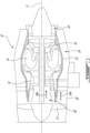
- FIG. 1 illustrates a gas turbine engine 10 of a type preferably provided for use in subsonic flight, generally comprising in serial flow communication, along central longitudinal axis 11, a fan 12 through which ambient air is propelled, a compressor section 14 for pressurizing the air, a combustor 16 in which the compressed air is mixed with fuel and ignited for generating an annular stream of hot combustion gases, and a turbine section 18 for extracting energy from the combustion gases.
- Engine 10 further includes an exhaust section 20 where hot combustion gases are expelled. While FIG. 1 depicts engine 10 as a turbofan-type gas turbine engine, the present invention may relate to other types of aircraft engines, such as turboprop engines, turboshaft engines, as well as hybrid-electric engines.
- the gas turbine engine 10 includes a first, inner casing 22 which encloses the turbo machinery of the engine, and a second, outer casing 24 extending outwardly of the first casing 22 such as to define an annular bypass passage 26 therebetween, also referred to as a bypass duct or an annular outer passage.
- the air propelled by the fan 12 is split into a first portion which flows around the first casing 22 within the bypass passage 26, and a second portion which flows through a main gas path 28, also referred to as a core passage, which is defined within the first casing 22 and allows the gas flow to circulate through the multistage compressor 14, combustor 16 and turbine section 18 as described above.
- a core gas flow 28a is said to flow through the main gas path 28 (also referred to as the core gas path), while a bypass gas flow 26a is said to flow through the bypass passage 26.
- engine 10 further includes an air-cooled heat exchanger 34 disposed adjacent the exhaust duct 30 and in fluid communication therewith.
- the air-cooled heat exchanger 34 is an air-cooled oil cooler, in which warm engine oil is operable to transfer heat to the cool air flowing therethrough.
- Other types of air-cooled heat exchangers may be contemplated.
- the air-cooled heat exchanger 34 receives cooling airflow 36a via an air inlet duct 36, and exhausts the cooling airflow 36a into the exhaust duct 30 via an air outlet duct 38.
- the outlet duct 38 includes one or more walls 38a. In the shown case, the outlet duct 38 has a rectangular cross-section, although other arrangements may be contemplated. For instance, the outlet duct 38 may have a cylindrical wall 38a.
- the air-cooled heat exchanger 34 includes an inlet 34a receiving the cooling airflow 36a from the inlet duct 36 and an outlet 34b for expelling the cooling airflow 36a through the outlet duct 38 towards the exhaust duct 30.
- the inlet duct 36 and outlet duct 38 may collectively be referred to as a heat exchanger duct.
- the cross-sectional shape of the heat exchanger duct may vary, for instance the cross-sectional shape may be circular, square, rectangular or another shape.
- the heat exchanger duct includes a cover 40, also referred to as a cover system.
- the heat exchanger duct, as well as the components found therewithin, may therefore be referred to as a heat exchanger duct assembly.
- the cover 40 is illustratively disposed in the outlet duct 38 portion of the heat exchanger duct, downstream of the air-cooled heat exchanger 34 and upstream of the exhaust duct 30. Other locations for the cover 40 maybe contemplated, for instance at the downstream end of the outlet duct 38, i.e., where the outlet duct 38 meets the exhaust duct 30.
- the depicted cover 40 also referred to as a cover mechanism, includes a closure 42 comprising a plurality of plates 44, also referred to as blinds or louvers, that are pivotally mounted to a duct wall 38a, illustratively via pins 46.
- the plates 44 are operatively coupled to one another via a rod 48 attached to each plate 44 at a distal end thereof, thereby intimately linking their pivoting motions (i.e., pivoting the plates 44 in unison).
- each plate 44 may be independently pivotable.
- Other locations for the rod 48 attachment, or means for linking the plates 44 to one another may be contemplated.
- Various numbers, shapes and sizes for the plates 44 may be contemplated.
- the plates 44 may be sized, shaped and arranged so that in their closed configuration, they substantially occupy a cross sectional area of the outlet duct 38.
- a linkage mechanism 50 operatively couples the closure 42 to a biasing member 52 (illustratively a plate) disposed in the exhaust duct 30 and exposed to the exhaust flow 30a.
- a force generated by the pressure of the exhaust flow 30a acts against the biasing member 52, said pressure being a function of an operating state of the engine 10.
- the exhaust flow 30a may flow with a first pressure at the operational condition of the engine 10 and generate a first force against the biasing member 52
- the exhaust flow 30a may flow with a second pressure (less than the first pressure) at the shutdown condition of the engine 10 and generate a second force (less than the first force) against the biasing member 52.
- biasing member 52 may bias the closure 42 between an open position ( FIG. 2A ) to fluidly connect the heat exchanger duct to the exhaust duct 30, and a closed position ( FIG. 2B ) to fluidly disconnect the heat exchanger from the exhaust duct 30.
- Various linkage mechanisms 50 and biasing members 52 may be contemplated, as will be discussed in further detail below.
- the biasing member 52 may generate a biasing force on the closure 42 to bias the closure 42 towards its closed position, for instance due to the force of gravity acting on the biasing member 52 or by way of an optional spring and/or weight added to the biasing member 52.
- the force generated by the pressure of the exhaust flow 30a thus acts against the biasing force of the biasing member in biasing the closure 42 towards its open position.
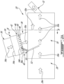
- FIG. 2A illustratively depicts the engine 10 in an operational or running state or condition.
- the core gas flow 28a flows through the main gas path 28, i.e., through the compressor section 14, combustor 16 and turbine section 18 towards the exhaust section 20 for evacuation from the engine 10, illustratively via external exhaust 32.
- an eductor effect may occur, whereby a cooling airflow 36a is drawn from a cooling airflow source (not shown), through the inlet duct 36 and through the air-cooled heat exchanger 34 before entering the exhaust duct 30 via the outlet duct 38.
- the cooling airflow source may be, for instance, the bypass gas flow 26a in the bypass passage 26, or ambient air source surrounding the engine 10.
- the cooling airflow 36a may be forcibly driven through the air-cooled heat exchanger 34 towards the exhaust duct 30, with the closure 42 in its open configuration.
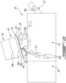
- FIG. 2B illustratively depicts the engine 10 in a non-operational or non-running state or condition, for instance after an engine shutdown procedure or condition.
- the core gas flow 28a is no longer actively flowing through the main gas path 28. Remaining or lingering core gas flow 28a, and exhaust flow 30a, may remain to be evacuated. As the core gas flow 28a and exhaust flow 30a are no longer actively flowing, there may no longer be a strong enough flow to create an eductor effect for drawing the cooling airflow 36a through the air-cooled heat exchanger 34.
- the outlet duct 38 is disposed above, i.e., in an upward direction from, the exhaust duct 30 relative to the longitudinal axis 11.
- the hot exhaust flow 30a may attempt to evacuate from the exhaust duct 30 upwardly via the outlet duct 38 instead of or in addition to via the external exhaust 32.
- the outlet duct 38 may be disposed adjacent or alongside the exhaust duct 30 relative to the longitudinal axis 11. In such a configuration, the adjacent outlet duct 38 may still provide a possible passageway for the hot exhaust flow 30a to evacuate from the exhaust duct 30.
- the air-cooled heat exchanger 34 may be a temperature-sensitive component, i.e., it includes one or more materials (e.g., aluminum) that are susceptible to damage (e.g., burning or melting) when exposed to excess heat.
- the core gas flow 28a exiting the main gas path 28 and the exhaust flow may be at temperatures of around 1000 degrees Fahrenheit (around 538 degrees Celsius). If such gases were to flow upstream into the outlet duct 38, they may melt, burn or otherwise damage one or more components of the air-cooled heat exchanger 34.
- the various tubes and fittings joining the air-cooled heat exchanger 34 to the heat exchanger duct may be susceptible to high temperature-related damage. The closure arrangement may thus prevent such damage.
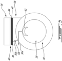
- the closure 42 is shown in the open position (see FIG. 2A ).
- the biasing member 52 is therefore biased or tilted forward and upward relative to the axis 11 by the incoming main gas path flow 28 and/or exhaust flow 30a during the operating condition of the engine 10, which motion actuates the linking mechanism 50 to bias the closure 42 into the open position.
- the linking mechanism 50 is formed by a pin slot arrangement (also referred to as a pin-sot linkage mechanism), whereby a first rotating arm 50a is operatively coupled to the biasing member 52 (and fixed to a duct wall 38a), a second rotating arm 50b is operatively coupled to one of the plates 44, with the first and second rotating arms 50a, 50b operatively coupled to one another at a pin slot 50c.
- a pin slot arrangement also referred to as a pin-sot linkage mechanism
- the biasing member 52 may be provided with a spring and/or weight to further contribute to the biasing force (i.e., assist its rearward and downward movement) at engine shutdown. This motion is transferred via the rotating arms 50a, 50b and pin slot 50c to one of the plates 44, which biases the other plates 44 (by way of the rod 48) into the closure's 42 closed position (see FIG.
- the linkage mechanism 50 may be operatively coupled directly to the rod 48 rather than to one of the plates 44.
- the plates 44 may pivot to extend transversally relative to the direction of the flow of the cooling air 36a blocking the previously-formed apertures between adjacent plates 44.
- the distal ends of the plates 44 may overlap one another in the closed position.
- rubber or other sealing materials may be disposed at distal ends of the plates 44 so that they may create an air-tight seal when in their closed position. As such, in the shutdown condition of the engine 10, hot exhaust flow 30a is prevented from travelling upstream in the outlet duct 38 towards the air-cooled heat exchanger 34 due to the closed closure 42.
- linkage mechanisms 50 may be contemplated, for instance a rack and pinion arrangement or a cable and yoke arrangement.
- components of the linkage mechanism 50 i.e., the rotating arms 50a, 50b
- the components of the linkage mechanism 50 are illustratively shown as being disposed internally in the outlet duct 38, one or more components of the linkage mechanism 50 may be disposed externally to the outlet duct 38.
- cover 40, linking mechanism 50 and biasing member 52 may allow cooling airflow 36a to flow from the air-cooled heat exchanger 34 to the exhaust duct 30 during the operating condition of the engine 10, but prevent hot gasses (i.e., exhaust flow 30a) from flowing upstream into the outlet duct 38 and through the air-cooled heat exchanger 34 (also referred to as a soak-back condition), which may be susceptible to temperature-related damage such as melting or burning.
- FIGS. 4A-4B another heat exchanger duct according to the present invention is shown, with like reference numerals referring to like elements. It is understood that various features shown in the heat exchanger duct of FIGS. 2A-3 may be implemented in the heat exchanger duct of FIGS. 4A-4B , and vice-versa.
- an evacuation valve 54 is provided in the outlet duct 38, downstream of the closure 42, for selectively evacuating hot exhaust gas 30a to an evacuation location, as will be discussed in further detail below.
- the closure 42 shown in FIGS. 4A-4B is arranged so that, in an operating condition of the engine 10 (shown in FIG.
- cooling air 36a is allowed to flow from the air-cooled exchanger 34, through the outlet duct 38, and into the exhaust duct 30 (having duct wall 30b) due to closure 42 being in an open position (while maintaining the valve 54 in a closed position), and so that in a shutdown condition of the engine 10 (shown in FIG. 4B ), the hot exhaust flow 30a is prevented from flowing upstream in the air outlet 38 towards the air-cooled heat exchanger 34 (due to closure 42 being in a closed position), and instead is evacuated via the valve 54 (now in an open position) to an evacuation location and/or continues to flow through the exhaust duct 30 towards the external exhaust 32 (not shown in FIGS. 4A-4B ).
- the valve 54 is movable between the open and closed positions or configurations based on an alteration of an operational condition or state of the engine 10. Stated differently, the valve 54 may assume its closed position in an engine operational condition (i.e., when then engine 10 is running), and may assume its open position in an engine shutdown state. As will be discussed in further detail below, the position of the valve 54 (and thus the operating condition of the engine 10) may correspond to the presence or absence of the cooling airflow 36a flowing through the air-cooled heat exchanger 34 towards the exhaust duct 30. The presence or absence of the flowing cooling airflow 36a, and thus the air pressure of the cooling airflow 36a, may cause the valve 54 to open or close. Other engine airflows may directly or indirectly affect the open or closed positions of the valve 54, as will be discussed in further detail below.
- the evacuation valve 54 is a spring-activated door comprising a door 54a, a spring 54b, and a hinge 54c.
- the hinge 54c is disposed at the downstream end of the door 54a relative to the flow of cooling air 36a in the heat exchanger duct, although the opposite arrangement (i.e., the hinge 54c disposed at the upstream end of the door 54a) may be contemplated.
- a force generated on the door 54a by the spring 54b may bias the door 54a open, as shown in FIG. 4B in the shutdown condition of the engine 10, thereby allowing the hot exhaust flow 30a to evacuate the outlet duct 38 towards the evacuation location.
- the flow of the cooling airflow 36a may generate a force against the door 54a that is opposite to and greater than the force of the spring 54b, thereby closing the door 54a.
- the valve 54 may thus be referred to as a passive valve, as it is biased between its open and closed positions based on the presence or absence of certain airflows in the outlet duct 38.
- the spring 54b may be omitted, and the hinged door 54a may bias open or closed solely based on the flow of the cooling airflow 36a (biasing the door 54a to the closed position due to negative pressure) or the flow of the hot exhaust flow 30a (biasing the door 54a to the open position due to positive pressure).
- Other valve types may be contemplated, for instance a thermally activated valve operable to bias towards the valve towards the closed position below a predetermined temperature associated with the operating condition of the engine 10 (e.g., indicative of the presence of the cooling airflow 36a in the outlet duct 38) and towards the open position above the predetermined temperature (e.g., indicative of the presence of hot exhaust flow in the outlet duct 38).
- Yet other valve types may be contemplated, such as mechanically-activated (e.g., solenoid) valves.
- a cover 40 is disposed in the outlet duct 38 downstream of the air-cooled heat exchanger 34.
- the cover 40 illustratively includes a closure 42 having plates 44 mounted to a duct wall 38a via pins 46 and operatively coupled to one another via rod 48.
- the closure is selectively displaceable between an open position ( FIG. 4A ) to fluidly connect the heat exchanger duct to the exhaust duct 30, and a closed position ( FIG. 4B ) to fluidly disconnect the heat exchanger from the exhaust duct 30.
- a linkage mechanism 50' operatively couples the cover 40 to a biasing member 52'.
- biasing member 52' may be disposed in the exhaust duct 30 and may be biased by a force generated by the flow of the core gas flow 28a, as was the case in the embodiment shown in FIGS. 2A-3 .
- the biasing member 52' may be disposed in another location in the engine 10 and may be exposed to another pressurized fluid flow for actuation thereof, the flow of said fluid indicative of the engine 10 being in the operating condition orthe shutdown condition.
- this position is transferred via the linking mechanism 50' to the rod 48, which biases the plates 44 into the closure's 42 open position (see FIG. 4A ).
- the cooling airflow 36a may flow through the outlet duct 38, through the open closure 42, into the exhaust duct 30.
- the biasing member 52' is biased to a second position indicative of the engine 10 being in the shutdown condition, and this position is transferred via the linking mechanism 50', which biases the plates 44 into the closure's 42 closed position (see FIG. 4B ).
- hot exhaust flow 30a is prevented from travelling upstream in the outlet duct 38 towards the air-cooled heat exchanger 34 due to the closed closure 42.
- the arrangement of the cover 40, the linking mechanism 50' and the biasing member 52', as well as the selective opening of the valve 54 may prevent hot gasses (i.e., exhaust flow 30a) from flowing upstream into the outlet duct 38 and through the air-cooled heat exchanger 34 (also referred to as a soak-back condition), which may be susceptible to temperature-related damage such as melting or burning.
- the linking mechanism 50' and biasing member 52' may be replaced with another actuating mechanism for biasing the plates 44, for instance a mechanically or electronically actuating module.
- FIGS. 5A-5B another heat exchanger duct according to the present invention is shown, with like reference numerals referring to like elements. It is understood that various features shown in the heat exchanger ducts of FIGS. 2A-4B may be implemented in the heat exchanger duct of FIGS. 5A-5B , and vice-versa.
- a cover 40" comprising a closure 42" is disposed in the outlet duct 38, illustratively at the downstream end of the outlet duct 38 relative to a flow direction of the cooling airflow 36a.
- a biasing member 52" is disposed in the exhaust duct 30 and exposed to the flow of the main gas path 28.
- the closure 42" is shown to be a single plate or paddle sized and dimensioned to correspond with a cross-sectional area of the outlet duct 38.
- the biasing member 52" is operatively coupled to the closure 42" via linking mechanism 50" and is operable to bias the closure 42" between an open position (represented in FIGS. 5A and 5B as broken lines) during an operational condition of the engine 10 and a closed position (represented in FIGS. 5A and 5B as solid lines) during a shutdown condition of the engine 10.
- the shown linking mechanism 50" illustratively includes a plurality of link members 50a" coupled together via pivots 50b" and operatively coupling the closure 42" to the biasing member 52" in a scissor linking mechanism.
- the linking mechanism 50 biases the closure 42" in a corresponding rearward and downward direction (i.e., the open position of the closure 42"), thereby allowing fluid communication between the outlet duct 38 and the exhaust duct 30.
- movement of the biasing member 52" is equal and opposite to movement of the closure 42" by way of the linking mechanism 50". In other cases, said movements may be opposite but proportional.
- the force acting against the biasing member 52" decreases and the biasing member 52" is biased rearward and downward (for instance, due to the force of gravity).
- the biasing member 52" may be provided with a spring and/or weight to further assist its rearward and downward movement at engine shutdown.
- This movement is transferred to the closure 42" via the linking mechanism 50", which displaces in a corresponding upward and forward manner (i.e., the closed position of the closure 42") to block or cover the outlet duct 38, thereby blocking fluid communication between the outlet duct 38 and the exhaust duct 30.
- the scissor-like displacement of the link members 50a" mirrors that of the closure 42" and the biasing member 52", in that their movement is intimately linked and they displace in concert either towards or away from each other.
- the arrangement of cover 40", linking mechanism 50" and biasing member 52" may allow cooling airflow 36a to flow from the air-cooled heat exchanger 34 to the exhaust duct 30 during the operating condition of the engine 10, but prevent hot gasses (i.e., exhaust flow 30a) from flowing upstream into the outlet duct 38 and through the air-cooled heat exchanger 34 (also referred to as a soak-back condition), which may be susceptible to temperature-related damage such as melting or burning.
- the cover 40, 40" may be said to be substantially closed (and the outlet duct 38 substantially sealed), as only a negligible volume of hot exhaust flow 30a is permitted to flow upstream into the outlet duct 38.
- the closure 42, 42" may be closed in a manner to better seal the outlet duct 38 in the closed position of the cover 40 (for instance, with rubber pieces disposed at distal ends of the plates 44 to abut and compress against adjacent plates 44) such that the cover 40, 40" may be said to be sealed in an airtight manner.
- an exemplary method for operating an aircraft engine 10.
- the aircraft engine 10 is operated in a powered mode that includes passing a gas through a heat exchanger 34 towards an exhaust duct 30 of the aircraft engine 10.
- the aircraft engine is transitioned from the powered mode into shut down, the transitioning including preventing exhaust gas 30a from flowing from the exhaust duct 30 towards the heat exchanger 34, said preventing including actuating a biasing member 52 disposed in the exhaust duct 30 to bias a closure 42 disposed fluidly between the heat exchanger 34 and the exhaust duct 30 closed.
- At least some embodiments have a passive, airflow-based system for preventing hot exhaust gasses from traveling upstream a heat exchanger duct, thereby allowing temperature-sensitive components of the heat exchanger to be protected at engine shutdown.
Landscapes
- Engineering & Computer Science (AREA)
- Mechanical Engineering (AREA)
- General Engineering & Computer Science (AREA)
- Chemical & Material Sciences (AREA)
- Combustion & Propulsion (AREA)
- Physics & Mathematics (AREA)
- Fluid Mechanics (AREA)
- Exhaust Silencers (AREA)
Abstract
An aircraft engine (10) comprises an exhaust duct (30) receiving an engine gas flow (30a) at a first pressure during an operating condition and at a second, lower pressure at shutdown. A heat exchanger (34) duct connected to the exhaust duct (30) has a heat exchanger (34) disposed therein. A cover (40) in the heat exchanger (34) duct includes a closure (42) movable between open and closed positions to fluidly connect or disconnect the heat exchanger duct to the exhaust duct (30). A biasing member (52) disposed in the exhaust duct (30), exposed to the gas flow (30a), and operatively connected to the closure (42) biases the closure (42) toward the closed position with a biasing force. First and second forces opposing the biasing force are generated on the biasing member (52) by the gas flow (30a) at the first and second pressures, the first being greater than the second. The biasing force is greater than the second force and less than the first force.
Description
- The present invention relates generally to aircraft engines, and more particularly, to exhaust flow management in aircraft engines.
- In some aircraft engines, a duct for an air-cooled heat exchanger has its outlet coupled to the engine's exhaust duct. As such, the core gas path flowing through the exhaust duct can draw ambient air through the heat exchanger duct. When the engine shuts down and the airflow through the main engine gas path stops, remaining hot exhaust gas in the exhaust duct may vent outwards through the heat exchanger duct. If the heat exchanger includes temperature-sensitive materials such as aluminum, it may be susceptible to temperature-related damage due to the hot exhaust gas flowing therethrough. Improvements are therefore desired.
- According to an aspect of the present invention, there is provided an aircraft engine, comprising: an exhaust duct receiving a gas flow from the aircraft engine, the gas flow being at a first pressure during an operating condition of the aircraft engine and at a second pressure during a shutdown condition of the aircraft engine, the second pressure being lower than the first pressure; a heat exchanger duct having an air inlet for receiving a flow of cooling air and an air outlet fluidly connected to the exhaust duct; an air-cooled heat exchanger disposed in the heat exchanger duct between the air inlet and the air outlet; a cover disposed in the heat exchanger duct downstream of the air-cooled heat exchanger, the cover including a closure movable between an open position to fluidly connect the heat exchanger duct to the exhaust duct, and a closed position to fluidly disconnect the heat exchanger duct from the exhaust duct; and a biasing member disposed in the exhaust duct, the biasing member exposed to the gas flow and operatively connected to the closure, the biasing member biasing the closure toward the closed position with a biasing force, a first force generated on the biasing member by the gas flow at the first pressure being greater than a second force generated on the biasing member by the gas flow at the second pressure, the first and second forces opposing the biasing force, the biasing force being greater than the second force and less than the first force.
- Optionally, and in accordance with the above, the closure includes a plurality of plates pivotally mounted to a duct wall of the heat exchanger duct and pivotable between the open position, in which the plates are aligned with a direction of the flow of cooling air in the heat exchanger duct, and the closed position, in which the plates extend transversally relative to the direction of the flow of the cooling air.
- Optionally, and in accordance with any of the above, the biasing member is operatively coupled to the closure via a pin-slot linkage mechanism.
- Optionally, and in accordance with any of the above, the aircraft engine further includes a rod operatively coupled to the biasing member and to distal ends of the plurality of plates, the plurality of plates pivotable in unison upon displacement of the rod.
- Optionally, and in accordance with any of the above, the closure includes a single plate, the single plate shaped and dimensioned to correspond with a cross-sectional area of the heat exchanger duct.
- Optionally, and in accordance with any of the above, the biasing member is operatively coupled to the single plate via a scissor linking mechanism.
- Optionally, and in accordance with any of the above, movement of the biasing member is equal and opposite to movement of the single plate by way of the scissor linking mechanism.
- Optionally, and in accordance with any of the above, the aircraft engine further includes a valve in a duct wall of the heat exchanger duct downstream of the closure, the valve selectively fluidly connecting the heat exchanger duct to an evacuation location, the valve being movable between a closed position during the operating condition of the aircraft engine to fluidly disconnect the heat exchanger duct to the evacuation location, and an open position during the shutdown condition of the aircraft engine to fluidly connect the heat exchanger duct to the evacuation location.
- Optionally, and in accordance with any of the above, the valve includes a spring operatively connected to a hinged door, the spring having a spring force biasing the hinged door into the open position, and wherein the flow of cooling air is at a first pressure during the operating condition of the aircraft engine and a second pressure during the shutdown condition of the aircraft engine, a first force generated on the hinged door by the flow of cooling air at the first pressure being greater than a second force generated on the hinged door by the flow of cooling air at the second pressure, the first and second forces opposing the spring force, the spring force being greater than the second force and less than the first force.
- According to another aspect of the present invention, there is provided a cover system for selectively allowing a flow of cooling air through a heat exchanger duct upstream of an exhaust duct in an aircraft engine, the heat exchanger duct including an air-cooled heat exchanger disposed therein, comprising: a source of pressurized fluid fluidly connected to the exhaust gas duct, the pressurized fluid flowing into the exhaust duct at a first pressure during an operating condition of the aircraft engine and at a second pressure during a shutdown condition of the aircraft engine, the second pressure being lower than the first pressure; a closure movable between an open position in which the closure fluidly connects the heat exchanger duct to the exhaust duct, and a closed position in which the closure fluidly disconnects the heat exchanger duct to the exhaust duct; and a biasing member disposed in the exhaust duct and operatively connected to the closure, the biasing member biasing the closure towards the closed position with a biasing force; wherein, during the operating condition of the aircraft engine, the first pressure of the pressurized fluid creates a first force acting against the biasing force of the biasing member, the first force being greater than the biasing force to urge the closure into the open position; and during the shutdown condition of the aircraft engine, the second pressure of the pressurized fluid creates a second force acting against the biasing force, the biasing force being greater than the second force to bias the closure into the closed position.
- Optionally, and in accordance with any of the above, the closure includes a plurality of plates pivotally mounted to a duct wall of the heat exchanger duct and pivotable between the open position, in which the plates are aligned with a direction of the flow of cooling air in the heat exchanger duct, and the closed position, in which the plates extend transversally relative to the direction of the flow of the cooling air.
- Optionally, and in accordance with any of the above, the biasing member is operatively coupled to the closure via a pin-slot linkage mechanism.
- Optionally, and in accordance with any of the above, the cover system further includes a rod operatively coupled to the biasing member and to distal ends of the plurality of plates, the plurality of plates pivotable in unison upon displacement of the rod.
- Optionally, and in accordance with any of the above, the closure includes a single plate, the single plate shaped and dimensioned to correspond with a cross-sectional area of the heat exchanger duct.
- Optionally, and in accordance with any of the above, the biasing member is operatively coupled to the single plate via a scissor linking mechanism.
- Optionally, and in accordance with any of the above, movement of the biasing member is equal and opposite to movement of the single plate by way of the scissor linking mechanism.
- Optionally, and in accordance with any of the above, the cover system further includes a valve in a duct wall of the heat exchanger duct downstream of the closure, the valve selectively fluidly connecting the heat exchanger duct to an evacuation location, the valve being movable between a closed position during the operating condition of the aircraft engine to fluidly disconnect the heat exchanger duct to the evacuation location, and an open position during the shutdown condition of the aircraft engine to fluidly connect the heat exchanger duct to the evacuation location.
- Optionally, and in accordance with any of the above, the valve includes a spring operatively connected to a hinged door, the spring having a spring force biasing the hinged door into the open position, and wherein the flow of cooling air is at a first pressure during the operating condition of the aircraft engine and a second pressure during the shutdown condition of the aircraft engine, a first force generated on the hinged door by the flow of cooling air at the first pressure being greater than a second force generated on the hinged door by the flow of cooling air at the second pressure, the first and second forces opposing the spring force, the spring force being greater than the second force and less than the first force.
- According to another aspect of the present invention, there is provided a method of operating an aircraft engine, comprising: operating the aircraft engine in a powered mode that includes passing a gas through a heat exchanger towards an exhaust duct of the aircraft engine; and transitioning the aircraft engine from the powered mode into shut down, the transitioning including preventing exhaust gas from flowing from the exhaust duct towards the heat exchanger, said preventing including actuating a biasing member disposed in the exhaust duct to bias a closure disposed fluidly between the heat exchanger and the exhaust duct closed.
- Optionally, and in accordance with any of the above, transitioning the aircraft engine from the powered mode into shut down further comprises evacuating the exhaust gas via an evacuation valve disposed fluidly between the heat exchanger and the exhaust duct.
- Features of the systems, devices and methods described herein may be used in various combinations, in accordance with the embodiments described herein.
- Reference is now made to the accompanying figures in which:
-
FIG. 1 is a schematic cross sectional view of a gas turbine engine; -
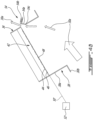
FIG. 2A is a schematic cross sectional view of an exhaust section of the engine ofFIG. 1 in a first engine operational mode; -
FIG. 2B is a schematic cross sectional view of an exhaust section of the engine ofFIG. 1 in a second engine operational mode; -
FIG. 3 is a schematic cross sectional view of the exhaust section ofFIG. 2A in the first engine operational mode taken along line III-III; -
FIG. 4A is a schematic cross sectional view of a heat exchanger duct for another embodiment of an exhaust section of the engine ofFIG. 1 in the first engine operational mode; -
FIG. 4B is a schematic cross sectional view of the heat exchanger duct ofFIG. 4A in the second engine operational mode; and -
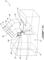
FIGS. 5A and5B are, respectively, schematic cross sectional and perspective views of another embodiment of an exhaust section of the engine ofFIG. 1 . -
FIG. 1 illustrates agas turbine engine 10 of a type preferably provided for use in subsonic flight, generally comprising in serial flow communication, along centrallongitudinal axis 11, afan 12 through which ambient air is propelled, acompressor section 14 for pressurizing the air, acombustor 16 in which the compressed air is mixed with fuel and ignited for generating an annular stream of hot combustion gases, and aturbine section 18 for extracting energy from the combustion gases.Engine 10 further includes anexhaust section 20 where hot combustion gases are expelled. WhileFIG. 1 depictsengine 10 as a turbofan-type gas turbine engine, the present invention may relate to other types of aircraft engines, such as turboprop engines, turboshaft engines, as well as hybrid-electric engines. - The
gas turbine engine 10 includes a first,inner casing 22 which encloses the turbo machinery of the engine, and a second,outer casing 24 extending outwardly of thefirst casing 22 such as to define anannular bypass passage 26 therebetween, also referred to as a bypass duct or an annular outer passage. The air propelled by thefan 12 is split into a first portion which flows around thefirst casing 22 within thebypass passage 26, and a second portion which flows through amain gas path 28, also referred to as a core passage, which is defined within thefirst casing 22 and allows the gas flow to circulate through themultistage compressor 14,combustor 16 andturbine section 18 as described above. Acore gas flow 28a is said to flow through the main gas path 28 (also referred to as the core gas path), while abypass gas flow 26a is said to flow through thebypass passage 26. - Referring additionally to
FIGS. 2A-2B , at theexhaust section 20 at the aft end of theengine 10, thecore gas flow 28a and thebypass gas flow 26a (seeFIG. 1 ) are exhausted from theengine 10 through anexhaust duct 30 and anexternal exhaust 32. In the depicted embodiment,engine 10 further includes an air-cooledheat exchanger 34 disposed adjacent theexhaust duct 30 and in fluid communication therewith. In an embodiment, the air-cooledheat exchanger 34 is an air-cooled oil cooler, in which warm engine oil is operable to transfer heat to the cool air flowing therethrough. Other types of air-cooled heat exchangers may be contemplated. In particular, the air-cooledheat exchanger 34 receivescooling airflow 36a via anair inlet duct 36, and exhausts thecooling airflow 36a into theexhaust duct 30 via anair outlet duct 38. Theoutlet duct 38 includes one ormore walls 38a. In the shown case, theoutlet duct 38 has a rectangular cross-section, although other arrangements may be contemplated. For instance, theoutlet duct 38 may have acylindrical wall 38a. The air-cooledheat exchanger 34 includes aninlet 34a receiving thecooling airflow 36a from theinlet duct 36 and anoutlet 34b for expelling thecooling airflow 36a through theoutlet duct 38 towards theexhaust duct 30. Theinlet duct 36 andoutlet duct 38 may collectively be referred to as a heat exchanger duct. The cross-sectional shape of the heat exchanger duct may vary, for instance the cross-sectional shape may be circular, square, rectangular or another shape. - Still referring to
FIGS. 2A-2B , according to an embodiment of the present invention, the heat exchanger duct includes acover 40, also referred to as a cover system. The heat exchanger duct, as well as the components found therewithin, may therefore be referred to as a heat exchanger duct assembly. Thecover 40 is illustratively disposed in theoutlet duct 38 portion of the heat exchanger duct, downstream of the air-cooledheat exchanger 34 and upstream of theexhaust duct 30. Other locations for thecover 40 maybe contemplated, for instance at the downstream end of theoutlet duct 38, i.e., where theoutlet duct 38 meets theexhaust duct 30. The depictedcover 40, also referred to as a cover mechanism, includes aclosure 42 comprising a plurality ofplates 44, also referred to as blinds or louvers, that are pivotally mounted to aduct wall 38a, illustratively via pins 46. In the shown case, theplates 44 are operatively coupled to one another via arod 48 attached to eachplate 44 at a distal end thereof, thereby intimately linking their pivoting motions (i.e., pivoting theplates 44 in unison). In other cases, eachplate 44 may be independently pivotable. Other locations for therod 48 attachment, or means for linking theplates 44 to one another, may be contemplated. Various numbers, shapes and sizes for theplates 44 may be contemplated. In some cases, a higher number ofshorter plates 44 may be used, whereas in other cases a lower number oflonger plates 44 may be used. Theplates 44 may be sized, shaped and arranged so that in their closed configuration, they substantially occupy a cross sectional area of theoutlet duct 38. - A
linkage mechanism 50 operatively couples theclosure 42 to a biasing member 52 (illustratively a plate) disposed in theexhaust duct 30 and exposed to theexhaust flow 30a. As will be discussed in further detail below, a force generated by the pressure of theexhaust flow 30a acts against the biasingmember 52, said pressure being a function of an operating state of theengine 10. In particular, theexhaust flow 30a may flow with a first pressure at the operational condition of theengine 10 and generate a first force against the biasingmember 52, and theexhaust flow 30a may flow with a second pressure (less than the first pressure) at the shutdown condition of theengine 10 and generate a second force (less than the first force) against the biasingmember 52. These applications of forces against the biasingmember 52 may bias theclosure 42 between an open position (FIG. 2A ) to fluidly connect the heat exchanger duct to theexhaust duct 30, and a closed position (FIG. 2B ) to fluidly disconnect the heat exchanger from theexhaust duct 30.Various linkage mechanisms 50 and biasingmembers 52 may be contemplated, as will be discussed in further detail below. The biasingmember 52 may generate a biasing force on theclosure 42 to bias theclosure 42 towards its closed position, for instance due to the force of gravity acting on the biasingmember 52 or by way of an optional spring and/or weight added to the biasingmember 52. The force generated by the pressure of theexhaust flow 30a thus acts against the biasing force of the biasing member in biasing theclosure 42 towards its open position. -
FIG. 2A illustratively depicts theengine 10 in an operational or running state or condition. Stated differently, thecore gas flow 28a flows through themain gas path 28, i.e., through thecompressor section 14,combustor 16 andturbine section 18 towards theexhaust section 20 for evacuation from theengine 10, illustratively viaexternal exhaust 32. As thecore gas flow 28a passes through theexhaust duct 30, an eductor effect may occur, whereby acooling airflow 36a is drawn from a cooling airflow source (not shown), through theinlet duct 36 and through the air-cooledheat exchanger 34 before entering theexhaust duct 30 via theoutlet duct 38. The cooling airflow source may be, for instance, thebypass gas flow 26a in thebypass passage 26, or ambient air source surrounding theengine 10. In some cases, in addition to or instead of flowing via an eductor effect, thecooling airflow 36a may be forcibly driven through the air-cooledheat exchanger 34 towards theexhaust duct 30, with theclosure 42 in its open configuration. -
FIG. 2B illustratively depicts theengine 10 in a non-operational or non-running state or condition, for instance after an engine shutdown procedure or condition. Stated differently, thecore gas flow 28a is no longer actively flowing through themain gas path 28. Remaining or lingeringcore gas flow 28a, andexhaust flow 30a, may remain to be evacuated. As thecore gas flow 28a andexhaust flow 30a are no longer actively flowing, there may no longer be a strong enough flow to create an eductor effect for drawing thecooling airflow 36a through the air-cooledheat exchanger 34. In addition, in the depicted embodiment, theoutlet duct 38 is disposed above, i.e., in an upward direction from, theexhaust duct 30 relative to thelongitudinal axis 11. As such, thehot exhaust flow 30a may attempt to evacuate from theexhaust duct 30 upwardly via theoutlet duct 38 instead of or in addition to via theexternal exhaust 32. In other cases, theoutlet duct 38 may be disposed adjacent or alongside theexhaust duct 30 relative to thelongitudinal axis 11. In such a configuration, theadjacent outlet duct 38 may still provide a possible passageway for thehot exhaust flow 30a to evacuate from theexhaust duct 30. In some embodiments, the air-cooledheat exchanger 34 may be a temperature-sensitive component, i.e., it includes one or more materials (e.g., aluminum) that are susceptible to damage (e.g., burning or melting) when exposed to excess heat. By closing theclosure 42 and preventinghot exhaust flow 30a from traveling upstream in the heat exchanger duct, heat-related damage to the air-cooledheat exchanger 34 due to exposure to thehot exhaust flow 30a may thus be prevented. - In an exemplary embodiment, the
core gas flow 28a exiting themain gas path 28 and the exhaust flow may be at temperatures of around 1000 degrees Fahrenheit (around 538 degrees Celsius). If such gases were to flow upstream into theoutlet duct 38, they may melt, burn or otherwise damage one or more components of the air-cooledheat exchanger 34. In addition, the various tubes and fittings joining the air-cooledheat exchanger 34 to the heat exchanger duct may be susceptible to high temperature-related damage. The closure arrangement may thus prevent such damage. - Referring to
FIG. 3 , theclosure 42 is shown in the open position (seeFIG. 2A ). The biasingmember 52 is therefore biased or tilted forward and upward relative to theaxis 11 by the incoming main gas path flow 28 and/orexhaust flow 30a during the operating condition of theengine 10, which motion actuates the linkingmechanism 50 to bias theclosure 42 into the open position. In the shown case, the linkingmechanism 50 is formed by a pin slot arrangement (also referred to as a pin-sot linkage mechanism), whereby a firstrotating arm 50a is operatively coupled to the biasing member 52 (and fixed to aduct wall 38a), a secondrotating arm 50b is operatively coupled to one of theplates 44, with the first and secondrotating arms pin slot 50c. Various shapes and sizes for the biasingmember 52 may be contemplated, for instance for improved aerodynamics and force/or generation. - In operation, as the biasing
member 52 is biased forward by the force generated by the incoming main gas path flow 28 and/orexhaust flow 30a, this motion is transferred via the rotatingarms pin slot 50c to one of the plates, which biases the other plates 44 (by way of the rod 48) into the closure's 42 open position (seeFIG. 2A ). In this open position, theplates 44 are pivoted to align with a direction of the flow of thecooling airflow 36a in the heat exchanger duct. As such, spaces or apertures are formed betweenadjacent plates 44, allowing thecooling airflow 36a to pass therethrough. As such, in the operating condition of theengine 10, thecooling airflow 36a may flow through theoutlet duct 38, through theopen closure 42, into theexhaust duct 30. - As the
engine 10 transitions to a shutdown condition, whereby the flow of the main gas path flow 28a slows to a stop, the force generated by the pressure of the incoming main gas path flow 28a and/orexhaust flow 30a decreases, and the basing force acting on the biasingmember 52 causes the biasingmember 52 to displace rearward and downward (seeFIG. 2B ). In some cases, the biasingmember 52 may be provided with a spring and/or weight to further contribute to the biasing force (i.e., assist its rearward and downward movement) at engine shutdown. This motion is transferred via the rotatingarms pin slot 50c to one of theplates 44, which biases the other plates 44 (by way of the rod 48) into the closure's 42 closed position (seeFIG. 2B ). In other cases, thelinkage mechanism 50 may be operatively coupled directly to therod 48 rather than to one of theplates 44. In this position, theplates 44 may pivot to extend transversally relative to the direction of the flow of the coolingair 36a blocking the previously-formed apertures betweenadjacent plates 44. In some cases, the distal ends of theplates 44 may overlap one another in the closed position. In some cases, rubber or other sealing materials may be disposed at distal ends of theplates 44 so that they may create an air-tight seal when in their closed position. As such, in the shutdown condition of theengine 10,hot exhaust flow 30a is prevented from travelling upstream in theoutlet duct 38 towards the air-cooledheat exchanger 34 due to theclosed closure 42.Other linkage mechanisms 50 may be contemplated, for instance a rack and pinion arrangement or a cable and yoke arrangement. In addition, while the components of the linkage mechanism 50 (i.e., the rotatingarms outlet duct 38, one or more components of thelinkage mechanism 50 may be disposed externally to theoutlet duct 38. Advantageously, the arrangement ofcover 40, linkingmechanism 50 and biasingmember 52 may allowcooling airflow 36a to flow from the air-cooledheat exchanger 34 to theexhaust duct 30 during the operating condition of theengine 10, but prevent hot gasses (i.e.,exhaust flow 30a) from flowing upstream into theoutlet duct 38 and through the air-cooled heat exchanger 34 (also referred to as a soak-back condition), which may be susceptible to temperature-related damage such as melting or burning. - Referring to
FIGS. 4A-4B , another heat exchanger duct according to the present invention is shown, with like reference numerals referring to like elements. It is understood that various features shown in the heat exchanger duct ofFIGS. 2A-3 may be implemented in the heat exchanger duct ofFIGS. 4A-4B , and vice-versa. In the shown case, anevacuation valve 54 is provided in theoutlet duct 38, downstream of theclosure 42, for selectively evacuatinghot exhaust gas 30a to an evacuation location, as will be discussed in further detail below. As was the case with the embodiment shown inFIGS. 2A-3 , theclosure 42 shown inFIGS. 4A-4B is arranged so that, in an operating condition of the engine 10 (shown inFIG. 4A ), coolingair 36a is allowed to flow from the air-cooledexchanger 34, through theoutlet duct 38, and into the exhaust duct 30 (havingduct wall 30b) due toclosure 42 being in an open position (while maintaining thevalve 54 in a closed position), and so that in a shutdown condition of the engine 10 (shown inFIG. 4B ), thehot exhaust flow 30a is prevented from flowing upstream in theair outlet 38 towards the air-cooled heat exchanger 34 (due toclosure 42 being in a closed position), and instead is evacuated via the valve 54 (now in an open position) to an evacuation location and/or continues to flow through theexhaust duct 30 towards the external exhaust 32 (not shown inFIGS. 4A-4B ). - As will be discussed in further detail below, the
valve 54 is movable between the open and closed positions or configurations based on an alteration of an operational condition or state of theengine 10. Stated differently, thevalve 54 may assume its closed position in an engine operational condition (i.e., when thenengine 10 is running), and may assume its open position in an engine shutdown state. As will be discussed in further detail below, the position of the valve 54 (and thus the operating condition of the engine 10) may correspond to the presence or absence of thecooling airflow 36a flowing through the air-cooledheat exchanger 34 towards theexhaust duct 30. The presence or absence of the flowingcooling airflow 36a, and thus the air pressure of thecooling airflow 36a, may cause thevalve 54 to open or close. Other engine airflows may directly or indirectly affect the open or closed positions of thevalve 54, as will be discussed in further detail below. - In the shown embodiment, but not necessarily the case in all embodiments, the
evacuation valve 54 is a spring-activated door comprising adoor 54a, aspring 54b, and ahinge 54c. In the shown case, thehinge 54c is disposed at the downstream end of thedoor 54a relative to the flow of coolingair 36a in the heat exchanger duct, although the opposite arrangement (i.e., thehinge 54c disposed at the upstream end of thedoor 54a) may be contemplated. A force generated on thedoor 54a by thespring 54b may bias thedoor 54a open, as shown inFIG. 4B in the shutdown condition of theengine 10, thereby allowing thehot exhaust flow 30a to evacuate theoutlet duct 38 towards the evacuation location. In the operating condition of theengine 10, the flow of thecooling airflow 36a may generate a force against thedoor 54a that is opposite to and greater than the force of thespring 54b, thereby closing thedoor 54a. Thevalve 54 may thus be referred to as a passive valve, as it is biased between its open and closed positions based on the presence or absence of certain airflows in theoutlet duct 38. - In other cases, the
spring 54b may be omitted, and the hingeddoor 54a may bias open or closed solely based on the flow of thecooling airflow 36a (biasing thedoor 54a to the closed position due to negative pressure) or the flow of thehot exhaust flow 30a (biasing thedoor 54a to the open position due to positive pressure). Other valve types may be contemplated, for instance a thermally activated valve operable to bias towards the valve towards the closed position below a predetermined temperature associated with the operating condition of the engine 10 (e.g., indicative of the presence of thecooling airflow 36a in the outlet duct 38) and towards the open position above the predetermined temperature (e.g., indicative of the presence of hot exhaust flow in the outlet duct 38). Yet other valve types may be contemplated, such as mechanically-activated (e.g., solenoid) valves. - As was the case in the embodiment shown in
FIGS. 2A-3 , acover 40 is disposed in theoutlet duct 38 downstream of the air-cooledheat exchanger 34. Thecover 40 illustratively includes aclosure 42 havingplates 44 mounted to aduct wall 38a viapins 46 and operatively coupled to one another viarod 48. The closure is selectively displaceable between an open position (FIG. 4A ) to fluidly connect the heat exchanger duct to theexhaust duct 30, and a closed position (FIG. 4B ) to fluidly disconnect the heat exchanger from theexhaust duct 30. A linkage mechanism 50' operatively couples thecover 40 to a biasing member 52'. In some cases, biasing member 52' may be disposed in theexhaust duct 30 and may be biased by a force generated by the flow of thecore gas flow 28a, as was the case in the embodiment shown inFIGS. 2A-3 . In other cases, the biasing member 52' may be disposed in another location in theengine 10 and may be exposed to another pressurized fluid flow for actuation thereof, the flow of said fluid indicative of theengine 10 being in the operating condition orthe shutdown condition. In operation, as the biasing member 52' is biased to a first position indicative of theengine 10 being in an operating condition, this position is transferred via the linking mechanism 50' to therod 48, which biases theplates 44 into the closure's 42 open position (seeFIG. 4A ). As such, in the operating condition of theengine 10, thecooling airflow 36a may flow through theoutlet duct 38, through theopen closure 42, into theexhaust duct 30. As theengine 10 transitions to a shutdown condition, the biasing member 52' is biased to a second position indicative of theengine 10 being in the shutdown condition, and this position is transferred via the linking mechanism 50', which biases theplates 44 into the closure's 42 closed position (seeFIG. 4B ). As such, in the shutdown condition of theengine 10,hot exhaust flow 30a is prevented from travelling upstream in theoutlet duct 38 towards the air-cooledheat exchanger 34 due to theclosed closure 42. Advantageously, the arrangement of thecover 40, the linking mechanism 50' and the biasing member 52', as well as the selective opening of thevalve 54 may prevent hot gasses (i.e.,exhaust flow 30a) from flowing upstream into theoutlet duct 38 and through the air-cooled heat exchanger 34 (also referred to as a soak-back condition), which may be susceptible to temperature-related damage such as melting or burning. In other cases, the linking mechanism 50' and biasing member 52' may be replaced with another actuating mechanism for biasing theplates 44, for instance a mechanically or electronically actuating module. - Referring to
FIGS. 5A-5B , another heat exchanger duct according to the present invention is shown, with like reference numerals referring to like elements. It is understood that various features shown in the heat exchanger ducts ofFIGS. 2A-4B may be implemented in the heat exchanger duct ofFIGS. 5A-5B , and vice-versa. As was the case with the heat exchanger duct shown inFIGS. 2A-2B , acover 40" comprising aclosure 42" is disposed in theoutlet duct 38, illustratively at the downstream end of theoutlet duct 38 relative to a flow direction of thecooling airflow 36a. A biasingmember 52" is disposed in theexhaust duct 30 and exposed to the flow of themain gas path 28. Theclosure 42" is shown to be a single plate or paddle sized and dimensioned to correspond with a cross-sectional area of theoutlet duct 38. The biasingmember 52" is operatively coupled to theclosure 42" via linkingmechanism 50" and is operable to bias theclosure 42" between an open position (represented inFIGS. 5A and5B as broken lines) during an operational condition of theengine 10 and a closed position (represented inFIGS. 5A and5B as solid lines) during a shutdown condition of theengine 10. - The shown linking
mechanism 50" illustratively includes a plurality oflink members 50a" coupled together viapivots 50b" and operatively coupling theclosure 42" to the biasingmember 52" in a scissor linking mechanism. Stated differently, as the biasingmember 52" is biased forward and upward relative to theaxis 11 by a force generated by the flow of thecore gas path 28a and/or theexhaust flow 30a (i.e., during an operating condition of the engine 10), the linkingmechanism 50" biases theclosure 42" in a corresponding rearward and downward direction (i.e., the open position of theclosure 42"), thereby allowing fluid communication between theoutlet duct 38 and theexhaust duct 30. Stated differently, movement of the biasingmember 52" is equal and opposite to movement of theclosure 42" by way of the linkingmechanism 50". In other cases, said movements may be opposite but proportional. Similarly, as the flow of thecore gas path 28a and/or theexhaust flow 30a slows and eventually stops (i.e., at a shutdown condition of the engine 10), the force acting against the biasingmember 52" decreases and the biasingmember 52" is biased rearward and downward (for instance, due to the force of gravity). In some cases, the biasingmember 52" may be provided with a spring and/or weight to further assist its rearward and downward movement at engine shutdown. This movement is transferred to theclosure 42" via thelinking mechanism 50", which displaces in a corresponding upward and forward manner (i.e., the closed position of theclosure 42") to block or cover theoutlet duct 38, thereby blocking fluid communication between theoutlet duct 38 and theexhaust duct 30. The scissor-like displacement of thelink members 50a" mirrors that of theclosure 42" and the biasingmember 52", in that their movement is intimately linked and they displace in concert either towards or away from each other. Advantageously, the arrangement ofcover 40", linkingmechanism 50" and biasingmember 52" may allowcooling airflow 36a to flow from the air-cooledheat exchanger 34 to theexhaust duct 30 during the operating condition of theengine 10, but prevent hot gasses (i.e.,exhaust flow 30a) from flowing upstream into theoutlet duct 38 and through the air-cooled heat exchanger 34 (also referred to as a soak-back condition), which may be susceptible to temperature-related damage such as melting or burning. - In various embodiments, the
cover outlet duct 38 substantially sealed), as only a negligible volume ofhot exhaust flow 30a is permitted to flow upstream into theoutlet duct 38. In other cases, theclosure outlet duct 38 in the closed position of the cover 40 (for instance, with rubber pieces disposed at distal ends of theplates 44 to abut and compress against adjacent plates 44) such that thecover - In accordance with the present invention, an exemplary method is shown for operating an
aircraft engine 10. Theaircraft engine 10 is operated in a powered mode that includes passing a gas through aheat exchanger 34 towards anexhaust duct 30 of theaircraft engine 10. The aircraft engine is transitioned from the powered mode into shut down, the transitioning including preventingexhaust gas 30a from flowing from theexhaust duct 30 towards theheat exchanger 34, said preventing including actuating a biasingmember 52 disposed in theexhaust duct 30 to bias aclosure 42 disposed fluidly between theheat exchanger 34 and theexhaust duct 30 closed. - It can be appreciated from the foregoing that at least some embodiments have a passive, airflow-based system for preventing hot exhaust gasses from traveling upstream a heat exchanger duct, thereby allowing temperature-sensitive components of the heat exchanger to be protected at engine shutdown.
- The embodiments described in this document provide non-limiting examples of possible implementations of the present technology. Upon review of the present invention, a person of ordinary skill in the art will recognize that changes may be made to the embodiments described herein without departing from the scope of the present technology. Yet further modifications could be implemented by a person of ordinary skill in the art in view of the present invention, which modifications would be within the scope of the present technology.
Claims (12)
- An aircraft engine (10) comprising:an exhaust duct (30) receiving a gas flow (28a) from the aircraft engine (10), the gas flow (28a) being at a first pressure during an operating condition of the aircraft engine (10) and at a second pressure during a shutdown condition of the aircraft engine (10), the second pressure being lower than the first pressure;a heat exchanger duct having an air inlet (36) for receiving a flow of cooling air (36a) and an air outlet (38) fluidly connected to the exhaust duct (30);an air-cooled heat exchanger (34) disposed in the heat exchanger duct between the air inlet (36) and the air outlet (38);a cover (40; 40") disposed in the heat exchanger duct downstream of the air-cooled heat exchanger (34), the cover (40; 40") including a closure (42; 42") movable between an open position to fluidly connect the heat exchanger duct to the exhaust duct (30), and a closed position to fluidly disconnect the heat exchanger duct from the exhaust duct (30); anda biasing member (52; 52'; 52") disposed in the exhaust duct (30), the biasing member (52; 52'; 52") exposed to the gas flow and operatively connected to the closure (42; 42"), the biasing member (52; 52'; 52") biasing the closure (42; 42") toward the closed position with a biasing force, a first force generated on the biasing member (52; 52'; 52") by the gas flow at the first pressure being greater than a second force generated on the biasing member (52; 52'; 52") by the gas flow at the second pressure, the first and second forces opposing the biasing force, the biasing force being greater than the second force and less than the first force.
- A cover system for selectively allowing a flow of cooling air (36a) through a heat exchanger duct upstream of an exhaust duct (30) in an aircraft engine (10), the heat exchanger duct including an air-cooled heat exchanger (34) disposed therein, the cover system comprising:a source of pressurized fluid (30a) fluidly connected to the exhaust duct (30), the pressurized fluid (30a) flowing into the exhaust duct (30) at a first pressure during an operating condition of the aircraft engine (10) and at a second pressure during a shutdown condition of the aircraft engine (10), the second pressure being lower than the first pressure;a closure (42; 42") movable between an open position in which the closure (42; 42") fluidly connects the heat exchanger duct to the exhaust duct (30), and a closed position in which the closure (42; 42") fluidly disconnects the heat exchanger duct to the exhaust duct (30); anda biasing member (52; 52'; 52") disposed in the exhaust duct (30) and operatively connected to the closure (42; 42"), the biasing member (52; 52'; 52") biasing the closure (42; 42") towards the closed position with a biasing force, wherein:during the operating condition of the aircraft engine (10), the first pressure of the pressurized fluid creates a first force acting against the biasing force of the biasing member (52; 52'; 52"), the first force being greater than the biasing force to urge the closure (42; 42") into the open position; andduring the shutdown condition of the aircraft engine (10), the second pressure of the pressurized fluid creates a second force acting against the biasing force, the biasing force being greater than the second force to bias the closure (42; 42") into the closed position.
- The aircraft engine (10) or the cover system as defined in claim 1 or 2, wherein the closure (42) includes a plurality of plates (44) pivotally mounted to a duct wall (38a) of the heat exchanger duct and pivotable between the open position, in which the plates (44) are aligned with a direction of the flow of cooling air (36a) in the heat exchanger duct, and the closed position, in which the plates (44) extend transversally relative to the direction of the flow of the cooling air (36a).
- The aircraft engine (10) or cover system as defined in claim 3, wherein the biasing member (52; 52') is operatively coupled to the closure (42) via a pin-slot linkage mechanism (50; 50').
- The aircraft engine (10) or cover system as defined in claim 3 or 4, further comprising a rod (48) operatively coupled to the biasing member (52; 52') and to distal ends of the plurality of plates (44), the plurality of plates (44) pivotable in unison upon displacement of the rod (48).
- The aircraft engine (10) or the cover system as defined in claim 1 or 2, wherein the closure (42") includes a single plate, the single plate shaped and dimensioned to correspond with a cross-sectional area of the heat exchanger duct.
- The aircraft engine (10) or cover system as defined in claim 6, wherein the biasing member (52") is operatively coupled to the single plate via a scissor linking mechanism (50").
- The aircraft engine (10) or cover system as defined in claim 7, wherein movement of the biasing member (52") is equal and opposite to movement of the single plate by way of the scissor linking mechanism (50").
- The aircraft engine (10) or cover system as defined in any preceding claim, further comprising a valve (54) in a duct wall (38a; 30b) of the heat exchanger duct downstream of the closure (42; 42"), the valve (54) selectively fluidly connecting the heat exchanger duct to an evacuation location, the valve (54) being movable between a closed position during the operating condition of the aircraft engine (10) to fluidly disconnect the heat exchanger duct to the evacuation location, and an open position during the shutdown condition of the aircraft engine (10) to fluidly connect the heat exchanger duct to the evacuation location.
- The aircraft engine (10) or cover system as defined in claim 9, wherein the valve (54) includes a spring (54b) operatively connected to a hinged door (54a), the spring (54b) having a spring force biasing the hinged door (54a) into the open position, and wherein the flow of cooling air (36a) is at a first pressure during the operating condition of the aircraft engine (10) and a second pressure during the shutdown condition of the aircraft engine (10), a first force generated on the hinged door (54a) by the flow of cooling air (36a) at the first pressure being greater than a second force generated on the hinged door (54a) by the flow of cooling air (36a) at the second pressure, the first and second forces opposing the spring force, the spring force being greater than the second force and less than the first force.
- A method of operating an aircraft engine (10), the method comprising:operating the aircraft engine (10) in a powered mode that includes passing a gas (36a) through a heat exchanger (34) towards an exhaust duct (30) of the aircraft engine (10); andtransitioning the aircraft engine (10) from the powered mode into shutdown, the transitioning including preventing exhaust gas (30a) from flowing from the exhaust duct (30) towards the heat exchanger (34), said preventing including actuating a biasing member (52; 52'; 52") disposed in the exhaust duct (30) to bias a closure (42; 42") disposed fluidly between the heat exchanger (34) and the exhaust duct (30) closed.
- The method as defined in claim 11, wherein transitioning the aircraft engine (10) from the powered mode into shut down further comprises evacuating the exhaust gas (30a) via an evacuation valve (54) disposed fluidly between the heat exchanger (34) and the exhaust duct (30).
Applications Claiming Priority (1)
| Application Number | Priority Date | Filing Date | Title |
|---|---|---|---|
| US18/337,678 US12203415B2 (en) | 2023-06-20 | 2023-06-20 | Engine exhaust reverse flow prevention |
Publications (1)
| Publication Number | Publication Date |
|---|---|
| EP4481177A1 true EP4481177A1 (en) | 2024-12-25 |
Family
ID=91617341
Family Applications (1)
| Application Number | Title | Priority Date | Filing Date |
|---|---|---|---|
| EP24183214.6A Pending EP4481177A1 (en) | 2023-06-20 | 2024-06-19 | Engine exhaust reverse flow prevention |
Country Status (3)
| Country | Link |
|---|---|
| US (1) | US12203415B2 (en) |
| EP (1) | EP4481177A1 (en) |
| CA (1) | CA3241473A1 (en) |
Families Citing this family (1)
| Publication number | Priority date | Publication date | Assignee | Title |
|---|---|---|---|---|
| US20250154878A1 (en) * | 2023-11-09 | 2025-05-15 | Rtx Corporation | Nose cone heat exchanger cooling airflow on open-rotor gas turbine engine |
Citations (4)
| Publication number | Priority date | Publication date | Assignee | Title |
|---|---|---|---|---|
| US5113649A (en) * | 1990-05-11 | 1992-05-19 | General Electric Company | Passive bypass valve assembly |
| US20060284015A1 (en) * | 2003-12-18 | 2006-12-21 | Pratt & Whitney Canada Corp. | Fire shield method |
| US20190145317A1 (en) * | 2017-11-14 | 2019-05-16 | Rolls-Royce Plc | Gas turbine engine having an air-oil heat exchanger |
| US20200011247A1 (en) * | 2018-07-05 | 2020-01-09 | United Technologies Corporation | Failure mitigation and failure detection of intercooled cooling air systems |
Family Cites Families (15)
| Publication number | Priority date | Publication date | Assignee | Title |
|---|---|---|---|---|
| US4203566A (en) | 1978-08-21 | 1980-05-20 | United Aircraft Products, Inc. | Air inlet control for aircraft or the like |
| GB0607773D0 (en) * | 2006-04-20 | 2006-05-31 | Rolls Royce Plc | A gas turbine engine |
| EP1936468A1 (en) | 2006-12-22 | 2008-06-25 | Siemens Aktiengesellschaft | Bi-metallic elements for adjusting a cooling channel |
| US8485222B2 (en) | 2007-01-31 | 2013-07-16 | Honeywell International Inc. | Systems and methods for preventing oil migration |
| US20090175718A1 (en) | 2007-12-31 | 2009-07-09 | Carlos Diaz | System and method for passive cooling of gas turbine engine control components |
| FR2930324B1 (en) | 2008-04-17 | 2011-06-17 | Snecma | DEVICE FOR COOLING A WALL |
| GB2468346B (en) | 2009-03-06 | 2011-06-22 | Rolls Royce Plc | Cooling system for an aero gas turbine engine |
| EP2472067B1 (en) | 2010-12-31 | 2013-09-25 | Techspace Aero S.A. | Integration of a surface heat exchanger with controlled air flow in an airplane engine |
| US9267390B2 (en) | 2012-03-22 | 2016-02-23 | Honeywell International Inc. | Bi-metallic actuator for selectively controlling air flow between plena in a gas turbine engine |
| GB201220378D0 (en) | 2012-11-13 | 2012-12-26 | Rolls Royce Plc | A gas turbine engine exhaust nozzle |
| FR3015573B1 (en) | 2013-12-19 | 2015-12-11 | Snecma | AIRCRAFT TURBOMACHINE COMPRISING A HEAT EXCHANGER OF THE PRE-COOLING TYPE |
| FR3028021B1 (en) | 2014-10-30 | 2019-03-22 | Safran Aircraft Engines | HEAT EXCHANGER TURBOMOTEUR COMPRISING SUCH AN EXCHANGER |
| US9903274B2 (en) | 2014-11-07 | 2018-02-27 | General Electric Company | Variable geometry heat exchanger apparatus |
| US10563936B2 (en) | 2016-07-19 | 2020-02-18 | Unison Industries, Llc | Passive heat exchanger valve |
| FR3072724A1 (en) | 2017-10-24 | 2019-04-26 | Airbus Operations (S.A.S.) | AIRCRAFT TURBOMACHINE COMPRISING A COMPARTMENT WITH A VENTILATION ASSEMBLY |
-
2023
- 2023-06-20 US US18/337,678 patent/US12203415B2/en active Active
-
2024
- 2024-06-11 CA CA3241473A patent/CA3241473A1/en active Pending
- 2024-06-19 EP EP24183214.6A patent/EP4481177A1/en active Pending
Patent Citations (4)
| Publication number | Priority date | Publication date | Assignee | Title |
|---|---|---|---|---|
| US5113649A (en) * | 1990-05-11 | 1992-05-19 | General Electric Company | Passive bypass valve assembly |
| US20060284015A1 (en) * | 2003-12-18 | 2006-12-21 | Pratt & Whitney Canada Corp. | Fire shield method |
| US20190145317A1 (en) * | 2017-11-14 | 2019-05-16 | Rolls-Royce Plc | Gas turbine engine having an air-oil heat exchanger |
| US20200011247A1 (en) * | 2018-07-05 | 2020-01-09 | United Technologies Corporation | Failure mitigation and failure detection of intercooled cooling air systems |
Also Published As
| Publication number | Publication date |
|---|---|
| CA3241473A1 (en) | 2025-06-09 |
| US12203415B2 (en) | 2025-01-21 |
| US20240426246A1 (en) | 2024-12-26 |
Similar Documents
| Publication | Publication Date | Title |
|---|---|---|
| US9267390B2 (en) | Bi-metallic actuator for selectively controlling air flow between plena in a gas turbine engine | |
| CN103375304B (en) | Modular louver system | |
| KR910006564B1 (en) | Exhaust nozzle with cooled flap | |
| US9045998B2 (en) | System for directing air flow to a plurality of plena | |
| EP2519723B1 (en) | Gas turbine engine | |
| US7861513B2 (en) | Aeroengine ventilation system | |
| US5586431A (en) | Aircraft nacelle ventilation and engine exhaust nozzle cooling | |
| EP3092388B1 (en) | Cross-stream heat exchanger | |
| US9068506B2 (en) | Turbine engine heat recuperator system | |
| JP6194413B2 (en) | Secondary nozzle for jet engine | |
| US7886520B2 (en) | Gas turbine engine | |
| EP2620618A2 (en) | Gas turbine engine in-board cooled cooling air system | |
| US10995678B2 (en) | Gas turbine engine with diversion pathway and semi-dimensional mass flow control | |
| US20100180571A1 (en) | Modulating flow through gas turbine engine cooling system | |
| US20190145316A1 (en) | Cooled Cooling Air System Having Shutoff Valve and Propulsor | |
| BR102016017667A2 (en) | gas turbine engines | |
| US12203415B2 (en) | Engine exhaust reverse flow prevention | |
| CN117125258B (en) | Auxiliary power unit system for aircraft | |
| CN105829692B (en) | Aircraft with jet cooling systems and jet cooling systems | |
| CN88102721A (en) | The exhaust gas nozzle that has cooling air diverter valve | |
| ES2435067T3 (en) | Turbine engine valve assembly | |
| CN120906690A (en) | Turbine engine precooling system and aircraft | |
| US12044173B1 (en) | Engine exhaust reverse flow prevention | |
| CN116601077A (en) | Spoons for aircraft turbine engines | |
| EP4464882A1 (en) | Aircraft engine exhaust reverse flow prevention |
Legal Events
| Date | Code | Title | Description |
|---|---|---|---|
| PUAI | Public reference made under article 153(3) epc to a published international application that has entered the european phase |
Free format text: ORIGINAL CODE: 0009012 |
|
| STAA | Information on the status of an ep patent application or granted ep patent |
Free format text: STATUS: THE APPLICATION HAS BEEN PUBLISHED |
|
| AK | Designated contracting states |
Kind code of ref document: A1 Designated state(s): AL AT BE BG CH CY CZ DE DK EE ES FI FR GB GR HR HU IE IS IT LI LT LU LV MC ME MK MT NL NO PL PT RO RS SE SI SK SM TR |
|
| STAA | Information on the status of an ep patent application or granted ep patent |
Free format text: STATUS: REQUEST FOR EXAMINATION WAS MADE |
|
| 17P | Request for examination filed |
Effective date: 20250624 |