EP4481175A1 - Auxiliary power unit with pulse detonation combustion - Google Patents
Auxiliary power unit with pulse detonation combustion Download PDFInfo
- Publication number
- EP4481175A1 EP4481175A1 EP24183348.2A EP24183348A EP4481175A1 EP 4481175 A1 EP4481175 A1 EP 4481175A1 EP 24183348 A EP24183348 A EP 24183348A EP 4481175 A1 EP4481175 A1 EP 4481175A1
- Authority
- EP
- European Patent Office
- Prior art keywords
- inlet
- discharge end
- detonation tube
- detonation
- auxiliary power
- Prior art date
- Legal status (The legal status is an assumption and is not a legal conclusion. Google has not performed a legal analysis and makes no representation as to the accuracy of the status listed.)
- Pending
Links
Images


Classifications
-
- F—MECHANICAL ENGINEERING; LIGHTING; HEATING; WEAPONS; BLASTING
- F02—COMBUSTION ENGINES; HOT-GAS OR COMBUSTION-PRODUCT ENGINE PLANTS
- F02C—GAS-TURBINE PLANTS; AIR INTAKES FOR JET-PROPULSION PLANTS; CONTROLLING FUEL SUPPLY IN AIR-BREATHING JET-PROPULSION PLANTS
- F02C5/00—Gas-turbine plants characterised by the working fluid being generated by intermittent combustion
- F02C5/10—Gas-turbine plants characterised by the working fluid being generated by intermittent combustion the working fluid forming a resonating or oscillating gas column, i.e. the combustion chambers having no positively actuated valves, e.g. using Helmholtz effect
- F02C5/11—Gas-turbine plants characterised by the working fluid being generated by intermittent combustion the working fluid forming a resonating or oscillating gas column, i.e. the combustion chambers having no positively actuated valves, e.g. using Helmholtz effect using valveless combustion chambers
-
- F—MECHANICAL ENGINEERING; LIGHTING; HEATING; WEAPONS; BLASTING
- F23—COMBUSTION APPARATUS; COMBUSTION PROCESSES
- F23R—GENERATING COMBUSTION PRODUCTS OF HIGH PRESSURE OR HIGH VELOCITY, e.g. GAS-TURBINE COMBUSTION CHAMBERS
- F23R7/00—Intermittent or explosive combustion chambers
-
- F—MECHANICAL ENGINEERING; LIGHTING; HEATING; WEAPONS; BLASTING
- F02—COMBUSTION ENGINES; HOT-GAS OR COMBUSTION-PRODUCT ENGINE PLANTS
- F02C—GAS-TURBINE PLANTS; AIR INTAKES FOR JET-PROPULSION PLANTS; CONTROLLING FUEL SUPPLY IN AIR-BREATHING JET-PROPULSION PLANTS
- F02C5/00—Gas-turbine plants characterised by the working fluid being generated by intermittent combustion
- F02C5/10—Gas-turbine plants characterised by the working fluid being generated by intermittent combustion the working fluid forming a resonating or oscillating gas column, i.e. the combustion chambers having no positively actuated valves, e.g. using Helmholtz effect
-
- F—MECHANICAL ENGINEERING; LIGHTING; HEATING; WEAPONS; BLASTING
- F05—INDEXING SCHEMES RELATING TO ENGINES OR PUMPS IN VARIOUS SUBCLASSES OF CLASSES F01-F04
- F05D—INDEXING SCHEME FOR ASPECTS RELATING TO NON-POSITIVE-DISPLACEMENT MACHINES OR ENGINES, GAS-TURBINES OR JET-PROPULSION PLANTS
- F05D2220/00—Application
- F05D2220/50—Application for auxiliary power units (APU's)
-
- F—MECHANICAL ENGINEERING; LIGHTING; HEATING; WEAPONS; BLASTING
- F05—INDEXING SCHEMES RELATING TO ENGINES OR PUMPS IN VARIOUS SUBCLASSES OF CLASSES F01-F04
- F05D—INDEXING SCHEME FOR ASPECTS RELATING TO NON-POSITIVE-DISPLACEMENT MACHINES OR ENGINES, GAS-TURBINES OR JET-PROPULSION PLANTS
- F05D2250/00—Geometry
- F05D2250/70—Shape
- F05D2250/71—Shape curved
Definitions
- the present invention relates generally to an auxiliary power unit that utilizes pulse detonation combustion tubes for improved power and fuel efficiency.
- An auxiliary power unit provides power to operate accessory devices and/or generate electric power independent of the propulsive engines of an aircraft.
- a conventional APU includes a compressor wheel driven by a turbine. Compressed air from the compressor is mixed with fuel in a combustor and ignited to generate an exhaust gas flow that drives the turbine. The turbine drives the compressor and a load such as generator, pump or other device utilized to operate accessory items and systems. Turbine engine manufacturers continue to seek further improvements to engine performance including improvements to thermal, transfer and fuel efficiencies.
- An auxiliary power unit includes a compressor that is coupled to an engine shaft that is disposed about an engine axis, a combustor assembly that is configured to generate an exhaust gas flow, the combustor assembly includes at least one detonation tube that defines a curved passage between an inlet that receives a compressed airflow and a discharge end.
- the combustor assembly further includes at least one fuel injector that is configured to inject fuel into the inlet and an igniter for igniting a fuel air mixture within the detonation tube near the discharge end.
- a turbine is coupled to the engine shaft that is configured to rotate in response to the exhaust gas flow that is communicated from the combustor assembly.
- a gas turbine engine includes a compressor that is coupled to an engine shaft that is disposed about an engine axis, a diffuser that receives compressed airflow from the compressor, a distribution manifold that receives the compressed airflow from the diffuser.
- a combustor assembly includes at least three detonation tubes, each of the detonation tubes define a curved passage between an inlet and a discharge end, the inlet includes an outer rounded cross-section and an inner converging/diverging venturi and is orientated transverse to an inlet flow of air such that air flows across the inlet, a fuel injector that is configured to inject fuel into the inlet, and an igniter for igniting a fuel air mixture within the detonation tube near the discharge end.
- a turbine is coupled to the engine shaft that is configured to rotate in response to an exhaust gas flow that is communicated from the combustor assembly.
- a method of operating an auxiliary power unit includes generating a standing pressure wave between an inlet and discharge end of a curved detonation tube, measuring a pressure differential between the inlet and a downstream location, injecting a quantity of fuel through the inlet in response to the measured pressure differential indicating a reversal of the standing pressure wave toward the discharge end, igniting a fuel air mixture with an igniter upon reaching a location proximate the discharge end, and discharging an exhaust gas flow through the discharge end to drive a turbine.
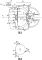
- FIG. 1 schematically illustrates an example auxiliary power unit (APU) 20 that includes pulse detonation tubes (PDT) 32 for generating an exhaust gas flow driving a turbine 26.
- PDT pulse detonation tubes
- the PDTs 32 operate as a resonant cavity to sustain a standing pressure wave. Fuel is injected into the PDTs 32 is timed to coincide with movement of standing wave toward a discharge end. The standing wave provides an increase in pressure of the output exhaust gas 48 driving the turbine 26 without a corresponding increase in load to provide improved engine operating efficiency.
- the example APU 20 is shown schematically as an example gas turbine engine utilizing the disclosed pulse detonated tubes 32.
- the example APU 20 is illustrated as driving a generator that is schematically shown at 18.
- the APU 20 may be configured to drive pumps, gearboxes or any other accessory component and/or system utilized to support operation of an aircraft or other vehicle.
- the specific configuration and structure of the APU 20 may differ from the disclosed example and remain with the contemplation of this disclosure.
- use of the disclosed PDTs 32 in other gas turbine engine architectures is also within the scope and contemplation of this disclosure.
- the example APU 20 includes a centrifugal compressor section 22 with a compressor impeller 38 coupled to a shaft 24 disposed along an engine axis A.
- a turbine 26 is also coupled to the shaft 24 and drives the compressor impeller 38.
- the turbine 26 includes a radial inlet 25 and an axial outlet 27.
- Inlet airflow 50 is compressed by the compressor impeller 38 and driven radially outward to a manifold 36 through a diffuser 34.
- the compressed airflow 52 is distributed to each of the PDTs 32 through the manifold 36 and into an inner cavity 54 defined within a combustor housing 30.
- Two PDTs 32 are shown in Figure 1 ; however, any number of PDTs 32 could be utilized within the scope and contemplation of this disclosure.
- a fuel system 44 provides a flow of fuel to a fuel injector 40 arranged at the PDT 32.
- the compressed airflow 52 is mixed with fuel 46 in the PDT 32 and ignited by an igniter 42 at a discharge end of the PDT 32 to generate the exhaust gas flow 48 that expands through the turbine 26.
- three PDTs 32 are arranged about the engine axis A and direct exhaust gas flow tangentially to the turbine 26. Although three PDTs 32 are shown by way of example, any number of PDTs may be utilized with the scope and contemplation of this disclosure. Moreover, the PDTs 32 could be operated in a synchronized fashion to provide an even flow of exhaust gas flow 48 to drive the turbine 26.
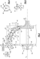
- the PDT 32 includes defines a curved passage between an inlet 68 and a discharge end 70.
- the inlet end 68 includes an outer thick rounded lip shape in cross-section 74 and an inner convergent-divergent nozzle 76.
- the discharge end 70 includes an inner convergent-divergent nozzle 78 that forms a turbine nozzle 62.
- the PDT 32 includes an inner diameter 58 and is curved at a radius 56 between the inlet 68 and the discharge end 70.
- the example radius 56 is between two (2) and five (5) times the inner diameter 58.
- the PDT 32 includes an inner radial surface 98 and an outer radial surface 100.
- the curved passage defined by the PDT 32 is arranged such that the inlet 68 is disposed radially outward from the discharge end 70.
- the PDT 32 has a length 60 along the curvature.
- the curved configuration of the PDT 32 generates a secondary flow 80 that aids in mixing injected fuel and air.
- the secondary flow 80 is transverse to a main flow direction indicated at 85 in Figure 3 .
- the curvature of the PDT 32 minimizes pressure loss while generating the secondary flow 80.
- the secondary flow 80 is generated by an inward pressure gradient in a direction toward the inner radial surface 98 opposing the centrifugal force in the main flow 85 generated by the curvature of the PDT 32 in a direction radially outward toward the outer radial surface 100.
- the PDT 32 secondary flow 80 moves inward under the pressure gradient and returns to the main flow 85 at an inner radial surface 98 of the PDT 32.
- the inner circulation induces large scale turbulence which increases flame propagation velocity by several orders of magnitude. Large deflagration flame velocity induces a rapid transition to detonation wave.
- the PDT 32 is disposed within a combustor housing 30 that defines an inner cavity 54.
- Compressed airflow 52 from the compressor impeller 38 is driven through a diffuser 34 to a distribution manifold 36.
- Compressed airflow 52 is also communicated into the cavity 54 and surrounds the PDT 32.
- the PDT 32 operates as a resonant cavity that increases the intensity of an acoustic pressure wave shown schematically at 82.
- the compressed airflow 52 is communicated across the inlet 68.
- the PDT 32 is filled with airflow 52 to generate the back-and-forth oscillating acoustic pressure wave 82.
- a "pumping" action is realized in the PDT 32 by flowing the compressed airflow 52 across the outer rounded profile end 74.
- the outer rounded profile end 74 is oriented perpendicular to the direction of airflow 52 into the manifold 36.
- the inlet orientation perpendicular to the airflow 52 generates a pumping action of airflow in the PDT 32.
- the PDT 32 operates as a harmonic oscillator wherein an initial airflow across the inlet 68 enters the PDT 32 at a total pressure that is higher than the pressure surrounding the inlet 68.
- the pressure within the PDT 32 is a combination of the ambient static pressure and a dynamic pressure. Once the PDT 32 is filled at the pressures higher, air within the PDT 32 will act against the lower pressure of the airflow 52 and then recede.
- the continued oscillation in pressures at the inlet 68 generate oscillating acoustic pressure wave schematically shown at 82 within the PDT 32.
- ignition of a fuel air mixture is induced at the discharge end of the PDT 32.
- the fuel 46 is injected into the inlet 68 in a compact coherent jet to avoid premature ignition.
- a stoichiometric fuel/air mixture is formed due to the inner secondary flow 80 as the combustible fuel/air mixture propagates downstream toward the discharge end 70.
- the fuel injection cycle is tuned to the PDT resonant frequency.
- the time origin for the injection cycle is updated constantly by reading a pressure differential with a differential pressure sensor 66.
- the pressure sensor 66 provides information indicative of a pressure differential in inlet venturi 76 and a downstream location 72.
- the standing acoustic pressure wave 82 moves between the inlet venturi 76 and the discharge end venturi 78.
- the pressure wave 82 reflects from each venturi 76, 78 and reverses direction through the PDT 32. Accordingly, the pressure wave 82 moving in a direction toward the inlet 68 reflects from the venturi 76, reverses direction and proceeds back toward the discharge end 70.
- the reflection of the pressure wave 82 signals the end of the cycle and is detected when the differential pressure read by the differential pressure sensor 66 is at a minimum, for example zero, due to the momentary flow reversal occurring as the pressure wave 82 reflects of the inlet venturi 76.
- a controller 64 uses the pressure difference information communicated by the differential pressure sensor 66 to actuate the fuel injector 40.
- the controller 64 is configured and programmed to control fuel injection timing based on the reversal of the pressure wave 82, among other things.
- the timing and the duty cycle of the fuel injection may vary depending on desired operation to control operation.
- the timing is the start of the cycle and the duty cycle is how long the injection of fuel lasts as a percentage of cycle length. Both may be adjusted and varied independently to tailor operation to desired and application specific operation.
- a detonation cycle is schematically illustrated in a linear representation of the curved PDT 32.
- Figure 6 illustrates the acoustic pressure wave 82 and a fuel/air mixture 84 proceeding through the PDT 32 toward the discharge end 70.
- Mach 1 (e.g., > 0.95).
- the arrival of the fuel/air mixture 84 in an ignition zone 102 near the discharge end 70 is timed to occur prior the arrival of the acoustic wave 82.
- the igniter 42 ignites the fuel/air mixture 84 near the discharge end 70 of the PDT 32.
- the ignition of the fuel/air mixture 84 generates a deflagration wave 86.
- the deflagration wave 86 propagates coincidental with the reflecting acoustic pressure wave 82 that has reversed direction and is proceeding back toward the inlet 68.
- the deflagration wave 86 amplifies pressures behind the reflected acoustic pressure wave 82.
- An exhaust gas flow 48 through the discharge end 70 is reduced due to lower density which provides for additional pressure build-up.
- the increased intensity acoustic wave 82 translates into a detonation wave, shown schematically at 88, which in combination with the lagging yet fast deflagration wave 86 increases the combustion rate by several orders of magnitude.
- the pressure behind the detonation wave 88, P dw indicated at 108, is more than double the compressor delivery pressure, P c indicated at 106, in front of the detonation wave 88 even for relatively low propagation speeds, such as for example speeds less than Mach 1.2.
- the detonation wave 88 continues to propagate toward the inlet 68 once it exits the combustible fuel/air mixture 84 and hot gas 90.
- the propagation velocity drops continuously as the pressure behind the detonation wave 88 drops.
- the detonation wave 88 slows and eventually transforms in the high intensity acoustic pressure wave 82 as shown in Figure 11 .
- the acoustic wave 82 reflects of the inlet venturi 76 and the pulse cycle repeats.
- the reflection of the high intensity pressure wave 82 results in a significant drop or reversal of air flow in the venturi 76 throat.
- the resulting pressure differential is reduced to a zero or near zero.
- the zero or near zero pressure differential is utilized as a prompt to inject fuel through the inlet 68.
- the fuel 46 is injected at the natural frequency of the PDT 32 with a pulse width sufficient to fill a portion of the PDT 32 depending on the instant air velocity.
- a passive flow of air passes through the PDT 32 between detonation cycles.
- the passive flow is that airflow that is not influenced by detonation of the fuel/air mixture 84.
- the passive flow provides for cooling of both the PDT 32 and the turbine 26.
- the PDT 32 includes walls 94 formed from porous material.
- the porous material provides for air within the combustor cavity 54 to at least partially permeate the walls 94 and cool the PDT 32.
- Compressed airflow 52 percolates from the volume of the cavity 54 surrounding the PDT 32 into and/or through the walls 94 as indicated schematically by arrows 92. The cooling provided by the surrounding air and the porous walls 94 occurs between each detonation cycle.
- a gas turbine engine or an auxiliary power unit includes, among other possible things, a compressor 22 that is coupled to an engine shaft 24 that is disposed about an engine axis, a combustor assembly 28 that is configured to generate an exhaust gas flow 48, the combustor assembly 28 includes at least one detonation tube 32 that defines a curved passage between an inlet 68 that receives a compressed airflow 52 and a discharge end 70.
- the combustor assembly 28 further includes at least one fuel injector 40 that is configured to inject fuel into the inlet 68, and an igniter 42 for igniting a fuel air mixture 84 within the detonation tube near the discharge end 70 (e.g. closer to the discharge end 70 than to the inlet 68).
- a turbine 26 is coupled to the engine shaft 24 that is configured to rotate in response to the exhaust gas flow 48 that is communicated from the combustor assembly 28.
- the auxiliary power unit may further include an inlet manifold 36 that directs compressed airflow 52 across the inlet 68 of the detonation tube 32.
- the inlet 68 may include an outer rounded cross-section and an inner converging/diverging cross-section (e.g., an inlet venturi 76).
- the discharge end 70 may include a converging/diverging cross-sectional shape (e.g., a discharge end venturi 78).
- the detonation tube 32 may include an inner diameter 58 and is curved between the inlet 68 and the discharge end 70 is at a radius between two and five times the inner diameter 58.
- the detonation tube 32 may be at least partially porous and may be disposed within a cavity 54 that is defined by the combustor case such that a cooling air at least partially permeates into the porous detonation tube 32.
- the auxiliary power unit may include a differential pressure sensor 66 that is configured to measure a pressure difference within the inlet 68 and a downstream location 72.
- the fuel injector 40 may be configured to inject fuel through the inlet 68 based on the pressure difference.
- the detonation tube 32 may be configured to generate a standing pressure wave 82 between the inlet 68 and the discharge end 70 and the fuel injector 40 may be configured to inject fuel through the inlet 68 in response to the pressure difference between the inlet 68 and the downstream location 72 that indicates a momentary reversal of the standing pressure wave 82.
- the at least one detonation tube 32 may include at least three detonation tubes that are arranged circumferentially about the engine axis.
- the discharge end 70 of each of the detonation tubes may be arranged to discharge the exhaust gas flow 48 tangentially into the turbine 26.
- the at least three detonation tubes may be operated sequentially.
- a gas turbine engine (e.g., a gas turbine engine configured as an auxiliary power unit) according to another exemplary embodiment of the invention includes, among other possible things, a compressor 22 that is coupled to an engine shaft 24 that is disposed about an engine axis (e.g., the compressor 22 of the auxiliary power unit 20), a diffuser 34 that receives compressed airflow 52 from the compressor 22, and a distribution manifold 36 that receives the compressed airflow 52 from the diffuser 34.
- a combustor assembly 28 (e.g., the combustor assembly 28 of the auxiliary power unit 20) includes at least three detonation tubes, each of the detonation tubes define a curved passage between an inlet 68 and a discharge end 70, the inlet 68 includes an outer rounded cross-section and an inner converging/diverging venturi 74,76 and is orientated transverse to an inlet flow of air such that air flows across the inlet 68, a fuel injector 40 that is configured to inject fuel into the inlet 68, and an igniter 42 for igniting a fuel air mixture 84 within the detonation tube near the discharge end 70 (e.g. closer to the discharge end 70 than to the inlet 68).
- a turbine 26 (e.g., the turbine 26 of the auxiliary power unit 20) is coupled to the engine shaft 24 that is configured to rotate in response to an exhaust gas flow 48 that is communicated from the combustor assembly 28.
- the detonation tube may include an inner diameter 58 and the curve between the inlet 68 and the discharge end 70 is at a radius between two and five times the inner diameter 58.
- the detonation tube 32 may be at least partially porous and is disposed within a cavity 54 that is defined by the combustor case such that a cooling air at least partially permeates into the porous detonation tube 32.
- the gas turbine engine may include a differential pressure sensor 66 that is configured to measure a pressure difference within the inlet 68 and a downstream location 72.
- the fuel injector 40 may be configured to inject fuel through the inlet 68 based on the pressure difference.
- the detonation tube 32 may be configured to generate a standing pressure wave 82 between the inlet 68 and the discharge end 70 and the fuel injector 40 may be configured to inject fuel through the inlet 68 in response to the pressure difference between the inlet 68 and the downstream location 72 that indicates a momentary reversal of the standing pressure wave 82.
- the turbine 26 may be a radial turbine that includes a radial inlet 25 and an axial outlet 27.
- a method of operating an auxiliary power unit assembly includes, among other possible things, generating a standing pressure wave 82 between an inlet 68 and discharge end 70 of a curved detonation tube, measuring a pressure differential between the inlet 68 and a downstream location 72, injecting a quantity of fuel through the inlet 68 in response to the measured pressure differential indicating a reversal of the standing pressure wave 82 toward the discharge end 70, igniting a fuel air mixture 84 with an igniter 42 upon the fuel air mixture reaching a location proximate the discharge end 70, and discharging an exhaust gas flow 48 through the discharge end 70 to drive a turbine 26.
- the method may include communicating an inlet flow of compressed air from a compressor section across the inlet 68.
- the method may include configuring the detonation tube 32 to have a radius of curvature that is between two and five times an inner diameter 58 of the detonation tube 32 and generating a secondary flow pattern that is transverse to the standing pressure wave 82 with the curved detonation tube 32.
- the method may include configuring the detonation tube 32 from a porous material (e.g., forming the detonation tube 32 from a porous material) and cooling the detonation tube 32 by providing cooling air to permeate the porous material.
- a porous material e.g., forming the detonation tube 32 from a porous material
- example disclosed combustor assembly utilizing PDTs provides improved operational performance and efficiencies while maintaining simple construction and operation.
Landscapes
- Engineering & Computer Science (AREA)
- Chemical & Material Sciences (AREA)
- Combustion & Propulsion (AREA)
- Mechanical Engineering (AREA)
- General Engineering & Computer Science (AREA)
- Fluidized-Bed Combustion And Resonant Combustion (AREA)
Abstract
An auxiliary power unit (20) includes a combustor assembly (28) that includes a pulse detonation tube (32) that defines a curved passage between an inlet (68) that receives a compressed airflow (52) and a discharge end (70). The detonation tube (32) operates as a resonant cavity (54) to sustain a standing pressure wave (82). Fuel (46) injected into the pulse detonation tube (32) is timed to coincide with movement of a standing wave toward a discharge end (70). The standing wave provides an increase in pressure of an output exhaust gas (48) driving the turbine (26) without a corresponding increase in load.
Description
- The present invention relates generally to an auxiliary power unit that utilizes pulse detonation combustion tubes for improved power and fuel efficiency.
- An auxiliary power unit (APU) provides power to operate accessory devices and/or generate electric power independent of the propulsive engines of an aircraft. A conventional APU includes a compressor wheel driven by a turbine. Compressed air from the compressor is mixed with fuel in a combustor and ignited to generate an exhaust gas flow that drives the turbine. The turbine drives the compressor and a load such as generator, pump or other device utilized to operate accessory items and systems. Turbine engine manufacturers continue to seek further improvements to engine performance including improvements to thermal, transfer and fuel efficiencies.
- An auxiliary power unit according to an aspect of the invention, among other possible things includes a compressor that is coupled to an engine shaft that is disposed about an engine axis, a combustor assembly that is configured to generate an exhaust gas flow, the combustor assembly includes at least one detonation tube that defines a curved passage between an inlet that receives a compressed airflow and a discharge end. The combustor assembly further includes at least one fuel injector that is configured to inject fuel into the inlet and an igniter for igniting a fuel air mixture within the detonation tube near the discharge end. A turbine is coupled to the engine shaft that is configured to rotate in response to the exhaust gas flow that is communicated from the combustor assembly.
- A gas turbine engine according to another aspect of the invention, among other possible things includes a compressor that is coupled to an engine shaft that is disposed about an engine axis, a diffuser that receives compressed airflow from the compressor, a distribution manifold that receives the compressed airflow from the diffuser. A combustor assembly includes at least three detonation tubes, each of the detonation tubes define a curved passage between an inlet and a discharge end, the inlet includes an outer rounded cross-section and an inner converging/diverging venturi and is orientated transverse to an inlet flow of air such that air flows across the inlet, a fuel injector that is configured to inject fuel into the inlet, and an igniter for igniting a fuel air mixture within the detonation tube near the discharge end. A turbine is coupled to the engine shaft that is configured to rotate in response to an exhaust gas flow that is communicated from the combustor assembly.
- A method of operating an auxiliary power unit according to another aspect of the invention, among other possible things includes generating a standing pressure wave between an inlet and discharge end of a curved detonation tube, measuring a pressure differential between the inlet and a downstream location, injecting a quantity of fuel through the inlet in response to the measured pressure differential indicating a reversal of the standing pressure wave toward the discharge end, igniting a fuel air mixture with an igniter upon reaching a location proximate the discharge end, and discharging an exhaust gas flow through the discharge end to drive a turbine.
- Although the different examples have the specific components shown in the illustrations, embodiments of this disclosure are not limited to those particular combinations. It is possible to use some of the components or features from one of the examples in combination with features or components from another one of the examples.
- These and other features disclosed herein can be best understood from the following specification and drawings, the following of which is a brief description.
-
-
Figure 1 is a schematic view of an example auxiliary power unit assembly including pulse detonation tubes. -
Figure 2 is an axial schematic view of a pulse detonation tubes arranged tangentially to a turbine. -
Figure 3 is a schematic view of an example combustor assembly including a pulse detonation tube. -
Figure 4 is a cross-section of a portion of an example pulse detonation tube. -
Figure 5 is a schematic cross-section of an inlet of the example pulse detonation tube. -
Figure 6 is a schematic linear representation of an example pulse detonation tube at a stage of an example detonation cycle. -
Figure 7 is a schematic linear representation of an example pulse detonation tube at another stage of an example detonation cycle. -
Figure 8 is a schematic linear representation of an example pulse detonation tube at yet another stage of an example detonation cycle. -
Figure 9 is a schematic linear representation of an example pulse detonation tube at still yet another stage of an example detonation cycle. -
Figure 10 is a schematic linear representation of an example pulse detonation tube at further still yet another stage of an example detonation cycle. -
Figure 11 is a schematic linear representation of an example pulse detonation tube at again further still another stage of an example detonation cycle. -
Figure 12 is a schematic view of a portion of an example pulse detonation tube. -
Figure 1 schematically illustrates an example auxiliary power unit (APU) 20 that includes pulse detonation tubes (PDT) 32 for generating an exhaust gas flow driving aturbine 26. ThePDTs 32 operate as a resonant cavity to sustain a standing pressure wave. Fuel is injected into thePDTs 32 is timed to coincide with movement of standing wave toward a discharge end. The standing wave provides an increase in pressure of theoutput exhaust gas 48 driving theturbine 26 without a corresponding increase in load to provide improved engine operating efficiency. - The
example APU 20 is shown schematically as an example gas turbine engine utilizing the disclosed pulse detonatedtubes 32. The example APU 20 is illustrated as driving a generator that is schematically shown at 18. However, the APU 20 may be configured to drive pumps, gearboxes or any other accessory component and/or system utilized to support operation of an aircraft or other vehicle. The specific configuration and structure of theAPU 20 may differ from the disclosed example and remain with the contemplation of this disclosure. Moreover, use of the disclosedPDTs 32 in other gas turbine engine architectures is also within the scope and contemplation of this disclosure. - The example APU 20 includes a
centrifugal compressor section 22 with acompressor impeller 38 coupled to ashaft 24 disposed along an engine axis A. Aturbine 26 is also coupled to theshaft 24 and drives thecompressor impeller 38. Theturbine 26 includes aradial inlet 25 and anaxial outlet 27.Inlet airflow 50 is compressed by thecompressor impeller 38 and driven radially outward to amanifold 36 through adiffuser 34. Thecompressed airflow 52 is distributed to each of thePDTs 32 through themanifold 36 and into aninner cavity 54 defined within acombustor housing 30. TwoPDTs 32 are shown inFigure 1 ; however, any number ofPDTs 32 could be utilized within the scope and contemplation of this disclosure. - A
fuel system 44 provides a flow of fuel to afuel injector 40 arranged at thePDT 32. Thecompressed airflow 52 is mixed withfuel 46 in thePDT 32 and ignited by anigniter 42 at a discharge end of thePDT 32 to generate theexhaust gas flow 48 that expands through theturbine 26. - Referring to
Figure 2 with continued reference toFigure 1 , threePDTs 32 are arranged about the engine axis A and direct exhaust gas flow tangentially to theturbine 26. Although threePDTs 32 are shown by way of example, any number of PDTs may be utilized with the scope and contemplation of this disclosure. Moreover, thePDTs 32 could be operated in a synchronized fashion to provide an even flow ofexhaust gas flow 48 to drive theturbine 26. - Referring to
Figure 3 , a portion of theexample combustor assembly 28 is shown along with anexample PDT 32. The PDT 32 includes defines a curved passage between aninlet 68 and adischarge end 70. Theinlet end 68 includes an outer thick rounded lip shape incross-section 74 and an inner convergent-divergent nozzle 76. Thedischarge end 70 includes an inner convergent-divergent nozzle 78 that forms aturbine nozzle 62. - The PDT 32 includes an
inner diameter 58 and is curved at aradius 56 between theinlet 68 and thedischarge end 70. Theexample radius 56 is between two (2) and five (5) times theinner diameter 58. The PDT 32 includes an innerradial surface 98 and an outerradial surface 100. The curved passage defined by thePDT 32 is arranged such that theinlet 68 is disposed radially outward from thedischarge end 70. The PDT 32 has alength 60 along the curvature. Thelength 60 is based on the wavelength of the standingpressure wave 82 generated within thePDT 32. In one example, thelength 60 is determined by the formula L= λ/2, where λ is the wavelength. - Referring to
Figure 4 , with continued reference toFigure 3 , the curved configuration of thePDT 32 generates asecondary flow 80 that aids in mixing injected fuel and air. Thesecondary flow 80 is transverse to a main flow direction indicated at 85 inFigure 3 . The curvature of thePDT 32 minimizes pressure loss while generating thesecondary flow 80. Thesecondary flow 80 is generated by an inward pressure gradient in a direction toward the innerradial surface 98 opposing the centrifugal force in themain flow 85 generated by the curvature of thePDT 32 in a direction radially outward toward the outerradial surface 100. ThePDT 32secondary flow 80 moves inward under the pressure gradient and returns to themain flow 85 at an innerradial surface 98 of thePDT 32. The inner circulation induces large scale turbulence which increases flame propagation velocity by several orders of magnitude. Large deflagration flame velocity induces a rapid transition to detonation wave. - Referring to
Figure 3 , thePDT 32 is disposed within acombustor housing 30 that defines aninner cavity 54.Compressed airflow 52 from thecompressor impeller 38 is driven through adiffuser 34 to adistribution manifold 36.Compressed airflow 52 is also communicated into thecavity 54 and surrounds thePDT 32. ThePDT 32 operates as a resonant cavity that increases the intensity of an acoustic pressure wave shown schematically at 82. - Referring to
Figure 5 , with continued reference toFigure 3 , thecompressed airflow 52 is communicated across theinlet 68. ThePDT 32 is filled withairflow 52 to generate the back-and-forth oscillatingacoustic pressure wave 82. A "pumping" action is realized in thePDT 32 by flowing thecompressed airflow 52 across the outerrounded profile end 74. The outerrounded profile end 74 is oriented perpendicular to the direction ofairflow 52 into themanifold 36. The inlet orientation perpendicular to theairflow 52 generates a pumping action of airflow in thePDT 32. ThePDT 32 operates as a harmonic oscillator wherein an initial airflow across theinlet 68 enters thePDT 32 at a total pressure that is higher than the pressure surrounding theinlet 68. The pressure within thePDT 32 is a combination of the ambient static pressure and a dynamic pressure. Once thePDT 32 is filled at the pressures higher, air within thePDT 32 will act against the lower pressure of theairflow 52 and then recede. The continued oscillation in pressures at theinlet 68 generate oscillating acoustic pressure wave schematically shown at 82 within thePDT 32. - Referring to
Figure 3 , ignition of a fuel air mixture is induced at the discharge end of thePDT 32. Thefuel 46 is injected into theinlet 68 in a compact coherent jet to avoid premature ignition. A stoichiometric fuel/air mixture is formed due to the innersecondary flow 80 as the combustible fuel/air mixture propagates downstream toward thedischarge end 70. The fuel injection cycle is tuned to the PDT resonant frequency. The time origin for the injection cycle is updated constantly by reading a pressure differential with adifferential pressure sensor 66. Thepressure sensor 66 provides information indicative of a pressure differential ininlet venturi 76 and adownstream location 72. - The standing
acoustic pressure wave 82 moves between theinlet venturi 76 and thedischarge end venturi 78. Thepressure wave 82 reflects from eachventuri PDT 32. Accordingly, thepressure wave 82 moving in a direction toward theinlet 68 reflects from theventuri 76, reverses direction and proceeds back toward thedischarge end 70. The reflection of thepressure wave 82 signals the end of the cycle and is detected when the differential pressure read by thedifferential pressure sensor 66 is at a minimum, for example zero, due to the momentary flow reversal occurring as thepressure wave 82 reflects of theinlet venturi 76. - A
controller 64 uses the pressure difference information communicated by thedifferential pressure sensor 66 to actuate thefuel injector 40. Thecontroller 64 is configured and programmed to control fuel injection timing based on the reversal of thepressure wave 82, among other things. The timing and the duty cycle of the fuel injection may vary depending on desired operation to control operation. The timing is the start of the cycle and the duty cycle is how long the injection of fuel lasts as a percentage of cycle length. Both may be adjusted and varied independently to tailor operation to desired and application specific operation. - Referring to
Figures 6-11 with continued reference toFigure 3 , a detonation cycle is schematically illustrated in a linear representation of thecurved PDT 32.Figure 6 illustrates theacoustic pressure wave 82 and a fuel/air mixture 84 proceeding through thePDT 32 toward thedischarge end 70. Theacoustic wave 82 bounces back and forth between theinlet 68 and thedischarge end 70 at about the speed of sound, Mach = 1 (e.g., > 0.95). The fuel/air mixture 84 propagates within thePDT 32 at a slower speed of around Mach = 0.3. - Referring to
Figure 7 , the arrival of the fuel/air mixture 84 in anignition zone 102 near thedischarge end 70 is timed to occur prior the arrival of theacoustic wave 82. As the fuel/air mixture 84 arrives in theignition zone 102, theigniter 42 ignites the fuel/air mixture 84 near the discharge end 70 of thePDT 32. The ignition of the fuel/air mixture 84 generates adeflagration wave 86. - Referring to
Figure 8 , thedeflagration wave 86 propagates coincidental with the reflectingacoustic pressure wave 82 that has reversed direction and is proceeding back toward theinlet 68. Thedeflagration wave 86 amplifies pressures behind the reflectedacoustic pressure wave 82. Anexhaust gas flow 48 through thedischarge end 70 is reduced due to lower density which provides for additional pressure build-up. - Referring to
Figure 9 , the increased intensityacoustic wave 82 translates into a detonation wave, shown schematically at 88, which in combination with the lagging yetfast deflagration wave 86 increases the combustion rate by several orders of magnitude. The pressure behind thedetonation wave 88, Pdw indicated at 108, is more than double the compressor delivery pressure, Pc indicated at 106, in front of thedetonation wave 88 even for relatively low propagation speeds, such as for example speeds less than Mach 1.2. - Referring to
Figure 10 , thedetonation wave 88 continues to propagate toward theinlet 68 once it exits the combustible fuel/air mixture 84 andhot gas 90. The propagation velocity drops continuously as the pressure behind thedetonation wave 88 drops. Thedetonation wave 88 slows and eventually transforms in the high intensityacoustic pressure wave 82 as shown inFigure 11 . - Referring to
Figure 11 , theacoustic wave 82 reflects of theinlet venturi 76 and the pulse cycle repeats. The reflection of the highintensity pressure wave 82 results in a significant drop or reversal of air flow in theventuri 76 throat. The resulting pressure differential is reduced to a zero or near zero. The zero or near zero pressure differential is utilized as a prompt to inject fuel through theinlet 68. Thefuel 46 is injected at the natural frequency of thePDT 32 with a pulse width sufficient to fill a portion of thePDT 32 depending on the instant air velocity. - A passive flow of air passes through the
PDT 32 between detonation cycles. The passive flow is that airflow that is not influenced by detonation of the fuel/air mixture 84. The passive flow provides for cooling of both thePDT 32 and theturbine 26. - Referring to
Figure 12 , with continued reference toFigures 3 and11 , thePDT 32 includeswalls 94 formed from porous material. The porous material provides for air within thecombustor cavity 54 to at least partially permeate thewalls 94 and cool thePDT 32.Compressed airflow 52 percolates from the volume of thecavity 54 surrounding thePDT 32 into and/or through thewalls 94 as indicated schematically byarrows 92. The cooling provided by the surrounding air and theporous walls 94 occurs between each detonation cycle. - Moreover, during re-charging with fuel, fuel evaporation will further cool the
PDT 32 along with the cooler air that percolates through theporous wall 94. During the combustion period, flow through theporous wall 94 reverses. However, the hot gases generated within thePDT 32 have low density and high viscosity, which significantly reduces the heating enthalpy (much lower mass flow at much higher temperature) compared to the cooling enthalpy brought in by the dense, low viscosity cold air from within thecombustor housing 30. The resulting average temperature of theporous wall 94 is therefore only marginally higher than the cooling air temperature. Moreover, heat it is also dissipated by conduction in the rest of thetube wall 94. - A gas turbine engine or an auxiliary power unit according to an exemplary embodiment of the invention includes, among other possible things, a
compressor 22 that is coupled to anengine shaft 24 that is disposed about an engine axis, acombustor assembly 28 that is configured to generate anexhaust gas flow 48, thecombustor assembly 28 includes at least onedetonation tube 32 that defines a curved passage between aninlet 68 that receives acompressed airflow 52 and adischarge end 70. Thecombustor assembly 28 further includes at least onefuel injector 40 that is configured to inject fuel into theinlet 68, and anigniter 42 for igniting afuel air mixture 84 within the detonation tube near the discharge end 70 (e.g. closer to thedischarge end 70 than to the inlet 68). Aturbine 26 is coupled to theengine shaft 24 that is configured to rotate in response to theexhaust gas flow 48 that is communicated from thecombustor assembly 28. - In an optional further embodiment of the foregoing, the auxiliary power unit may further include an
inlet manifold 36 that directs compressedairflow 52 across theinlet 68 of thedetonation tube 32. - In an optional further embodiment of any of the foregoing auxiliary power units, the
inlet 68 may include an outer rounded cross-section and an inner converging/diverging cross-section (e.g., an inlet venturi 76). - In an optional further embodiment of any of the foregoing auxiliary power units, the
discharge end 70 may include a converging/diverging cross-sectional shape (e.g., a discharge end venturi 78). - In an optional further embodiment of any of the foregoing auxiliary power units, the
detonation tube 32 may include aninner diameter 58 and is curved between theinlet 68 and thedischarge end 70 is at a radius between two and five times theinner diameter 58. - In an optional further embodiment of any of the foregoing auxiliary power units, the
detonation tube 32 may be at least partially porous and may be disposed within acavity 54 that is defined by the combustor case such that a cooling air at least partially permeates into theporous detonation tube 32. - In an optional further embodiment of any of the foregoing, the auxiliary power unit may include a
differential pressure sensor 66 that is configured to measure a pressure difference within theinlet 68 and adownstream location 72. Thefuel injector 40 may be configured to inject fuel through theinlet 68 based on the pressure difference. - In an optional further embodiment of any of the foregoing auxiliary power units, the
detonation tube 32 may be configured to generate a standingpressure wave 82 between theinlet 68 and thedischarge end 70 and thefuel injector 40 may be configured to inject fuel through theinlet 68 in response to the pressure difference between theinlet 68 and thedownstream location 72 that indicates a momentary reversal of the standingpressure wave 82. - In an optional further embodiment of any of the foregoing auxiliary power units, the at least one
detonation tube 32 may include at least three detonation tubes that are arranged circumferentially about the engine axis. Thedischarge end 70 of each of the detonation tubes may be arranged to discharge theexhaust gas flow 48 tangentially into theturbine 26. - In an optional further embodiment of any of the foregoing auxiliary power units, the at least three detonation tubes may be operated sequentially.
- A gas turbine engine (e.g., a gas turbine engine configured as an auxiliary power unit) according to another exemplary embodiment of the invention includes, among other possible things, a
compressor 22 that is coupled to anengine shaft 24 that is disposed about an engine axis (e.g., thecompressor 22 of the auxiliary power unit 20), adiffuser 34 that receivescompressed airflow 52 from thecompressor 22, and adistribution manifold 36 that receives the compressedairflow 52 from thediffuser 34. A combustor assembly 28 (e.g., thecombustor assembly 28 of the auxiliary power unit 20) includes at least three detonation tubes, each of the detonation tubes define a curved passage between aninlet 68 and adischarge end 70, theinlet 68 includes an outer rounded cross-section and an inner converging/divergingventuri inlet 68, afuel injector 40 that is configured to inject fuel into theinlet 68, and anigniter 42 for igniting afuel air mixture 84 within the detonation tube near the discharge end 70 (e.g. closer to thedischarge end 70 than to the inlet 68). A turbine 26 (e.g., theturbine 26 of the auxiliary power unit 20) is coupled to theengine shaft 24 that is configured to rotate in response to anexhaust gas flow 48 that is communicated from thecombustor assembly 28. - In an optional further embodiment of the foregoing gas turbine engine, the detonation tube may include an
inner diameter 58 and the curve between theinlet 68 and thedischarge end 70 is at a radius between two and five times theinner diameter 58. - In an optional further embodiment of any of the foregoing gas turbine engines, the
detonation tube 32 may be at least partially porous and is disposed within acavity 54 that is defined by the combustor case such that a cooling air at least partially permeates into theporous detonation tube 32. - In an optional further embodiment of any of the foregoing, the gas turbine engine may include a
differential pressure sensor 66 that is configured to measure a pressure difference within theinlet 68 and adownstream location 72. Thefuel injector 40 may be configured to inject fuel through theinlet 68 based on the pressure difference. - In an optional further embodiment of any of the foregoing gas turbine engines, the
detonation tube 32 may be configured to generate a standingpressure wave 82 between theinlet 68 and thedischarge end 70 and thefuel injector 40 may be configured to inject fuel through theinlet 68 in response to the pressure difference between theinlet 68 and thedownstream location 72 that indicates a momentary reversal of the standingpressure wave 82. - In an optional further embodiment of any of the foregoing gas turbine engines, the
turbine 26 may be a radial turbine that includes aradial inlet 25 and anaxial outlet 27. - A method of operating an auxiliary power unit assembly according to another exemplary embodiment of the invention includes, among other possible things, generating a standing
pressure wave 82 between aninlet 68 and discharge end 70 of a curved detonation tube, measuring a pressure differential between theinlet 68 and adownstream location 72, injecting a quantity of fuel through theinlet 68 in response to the measured pressure differential indicating a reversal of the standingpressure wave 82 toward thedischarge end 70, igniting afuel air mixture 84 with anigniter 42 upon the fuel air mixture reaching a location proximate thedischarge end 70, and discharging anexhaust gas flow 48 through thedischarge end 70 to drive aturbine 26. - In an optional further embodiment of the foregoing, the method may include communicating an inlet flow of compressed air from a compressor section across the
inlet 68. - In an optional further embodiment of any of the foregoing, the method may include configuring the
detonation tube 32 to have a radius of curvature that is between two and five times aninner diameter 58 of thedetonation tube 32 and generating a secondary flow pattern that is transverse to the standingpressure wave 82 with thecurved detonation tube 32. - In an optional further embodiment of any of the foregoing, the method may include configuring the
detonation tube 32 from a porous material (e.g., forming thedetonation tube 32 from a porous material) and cooling thedetonation tube 32 by providing cooling air to permeate the porous material. - Accordingly, example disclosed combustor assembly utilizing PDTs provides improved operational performance and efficiencies while maintaining simple construction and operation.
- Although an example embodiment has been disclosed, a worker of ordinary skill in this art would recognize that certain modifications would come within the scope of this disclosure. For that reason, the following claims should be studied to determine the scope and content of this disclosure.
Claims (15)
- An auxiliary power unit (20) comprising:a compressor (22) coupled to an engine shaft (24) disposed about an engine axis;a combustor assembly (28) configured to generate an exhaust gas flow (48), the combustor assembly (28) including at least one detonation tube (32) defining a curved passage, between an inlet (68) receiving a compressed airflow (52) and a discharge end (70), and at least one fuel injector (40) configured to inject fuel (46) into the inlet (68);an igniter (42) for igniting a fuel air mixture (84) within the at least one detonation tube (32) near the discharge end (70); anda turbine (26) coupled to the engine shaft (24) configured to rotate in response to the exhaust gas flow (48) communicated from the combustor assembly (28).
- The auxiliary power unit (20) as recited in claim 1, further comprising an inlet manifold (36) directing compressed airflow (52) across the inlet (68) of the detonation tube (32).
- The auxiliary power unit (20) as recited in claim 1 or 2, wherein:the inlet (68) comprises an outer rounded cross-section (74) and an inner converging/diverging cross-section (76); and/orthe discharge end (70) comprises a converging/diverging cross-sectional shape.
- The auxiliary power unit (20) as recited in any preceding claim, wherein the detonation tube (32) includes an inner diameter (58) and is curved between the inlet (68) and the discharge end (70) at a radius (56) between two and five times the inner diameter (58).
- The auxiliary power unit (20) as recited in any preceding claim, wherein the at least one detonation tube (32) includes at least three detonation tubes arranged circumferentially about the engine axis, and the discharge end (70) of each of the detonation tubes is arranged to discharge the exhaust gas flow (48) tangentially into the turbine (26), wherein, optionally, the at least three detonation tubes are operated sequentially.
- A gas turbine engine (20) comprising:a compressor (22) coupled to an engine shaft (24) disposed about an engine axis;a diffuser (34) receiving compressed airflow (52) from the compressor (22);a distribution manifold (36) receiving the compressed airflow (52) from the diffuser (34);a combustor assembly (28) including:at least three detonation tubes, wherein each of the detonation tubes defines a curved passage between an inlet (68) and a discharge end (70), and the inlet (68) includes an outer rounded cross-section (74) and an inner converging/diverging venturi (76) and is orientated transverse to an inlet (68) flow of air such that air flows across the inlet (68);a fuel injector (40) configured to inject fuel (46) into the inlet (68); andan igniter (42) for igniting a fuel air mixture (84) within the detonation tube (32) near the discharge end (70); anda turbine (26) coupled to the engine shaft (24) configured to rotate in response to an exhaust gas flow (48) communicated from the combustor assembly (28).
- The gas turbine engine (20) as recited in claim 6, wherein the detonation tube (32) includes an inner diameter (58) and the curve between the inlet (68) and the discharge end (70) is at a radius (56) between two and five times the inner diameter (58).
- The auxiliary power unit (20) or the gas turbine engine (20) as recited in any preceding claim, wherein the detonation tube (32) is at least partially porous and is disposed within a cavity (54) defined by a combustor case such that a cooling air at least partially permeates into the porous detonation tube (32).
- The auxiliary power unit (20) or the gas turbine engine (20) as recited in any preceding claim, including a differential pressure sensor (66) configured to measure a pressure difference between the inlet (68) and a downstream location (72), wherein the fuel injector (40) is configured to inject fuel (46) through the inlet (68) based on the pressure difference.
- The auxiliary power unit (20) or the gas turbine engine (20) as recited in claim 9, wherein the detonation tube (32) is configured to generate a standing pressure wave (82) between the inlet (68) and the discharge end (70) and the fuel injector (40) is configured to inject fuel (46) through the inlet (68) in response to the pressure difference between the inlet (68) and the downstream location (72) indicating a momentary reversal of the standing pressure wave (82).
- The auxiliary power unit (20) or the gas turbine engine (20) as recited in any preceding claim, wherein the turbine (26) is a radial turbine (26) including a radial inlet (25) and an axial outlet (27).
- A method of operating an auxiliary power unit (20) comprising:generating a standing pressure wave (82) between an inlet (68) and discharge end (70) of a curved detonation tube (32);measuring a pressure differential between the inlet (68) and a downstream location (72);injecting a quantity of fuel (46) through the inlet (68) in response to the measured pressure differential indicating a reversal of the standing pressure wave (82) toward the discharge end (70);igniting a fuel air mixture (84) with an igniter (42) upon reaching a location proximate the discharge end (70); anddischarging an exhaust gas flow (48) through the discharge end (70) to drive a turbine (26).
- The method as recited in claim 12, further including communicating an inlet (68) flow of compressed air from a compressor (22) section across the inlet (68).
- The method as recited in claim 12 or 13, further including configuring the detonation tube (32) to have a radius (56) of curvature that is between two and five times an inner diameter (58) of the detonation tube (32) and generating a secondary flow (80) pattern transverse to the standing pressure wave (82) with the curved detonation tube (32).
- The method as recited in claim 12, 13 or 14, further including configuring the detonation tube (32) from a porous material and cooling the detonation tube (32) by providing cooling air to permeate the porous material.
Applications Claiming Priority (1)
| Application Number | Priority Date | Filing Date | Title |
|---|---|---|---|
| US18/337,816 US12510249B2 (en) | 2023-06-20 | 2023-06-20 | Auxiliary power unit with pulse detonation combustion |
Publications (1)
| Publication Number | Publication Date |
|---|---|
| EP4481175A1 true EP4481175A1 (en) | 2024-12-25 |
Family
ID=91621170
Family Applications (1)
| Application Number | Title | Priority Date | Filing Date |
|---|---|---|---|
| EP24183348.2A Pending EP4481175A1 (en) | 2023-06-20 | 2024-06-20 | Auxiliary power unit with pulse detonation combustion |
Country Status (3)
| Country | Link |
|---|---|
| US (1) | US12510249B2 (en) |
| EP (1) | EP4481175A1 (en) |
| CA (1) | CA3239958A1 (en) |
Citations (3)
| Publication number | Priority date | Publication date | Assignee | Title |
|---|---|---|---|---|
| CH233945A (en) * | 1942-12-29 | 1944-08-31 | Sulzer Ag | Process for generating propellant gases by means of oscillating gases and gas piston propellant gas generators for carrying out the process. |
| US4175380A (en) * | 1978-03-24 | 1979-11-27 | Baycura Orestes M | Low noise gas turbine |
| US20050284127A1 (en) * | 2004-06-29 | 2005-12-29 | Akihiro Tobita | Detonation engine and flying object provided therewith |
Family Cites Families (14)
| Publication number | Priority date | Publication date | Assignee | Title |
|---|---|---|---|---|
| US2731795A (en) * | 1956-01-24 | bodine | ||
| US2543758A (en) * | 1947-06-13 | 1951-03-06 | Jr Albert G Bodine | Standing wave heat engine with means for supplying auxiliary air |
| US2593523A (en) * | 1948-05-05 | 1952-04-22 | Snecma | Gas turbine engine with resonating combustion chambers |
| US3035413A (en) * | 1950-01-17 | 1962-05-22 | Linderoth Erik Torvald | Thermodynamic combustion device using pulsating gas pressure |
| US2748564A (en) * | 1951-03-16 | 1956-06-05 | Snecma | Intermittent combustion gas turbine engine |
| US7047724B2 (en) * | 2002-12-30 | 2006-05-23 | United Technologies Corporation | Combustion ignition |
| US6901738B2 (en) * | 2003-06-26 | 2005-06-07 | United Technologies Corporation | Pulsed combustion turbine engine |
| US7818956B2 (en) * | 2005-05-13 | 2010-10-26 | General Electric Company | Pulse detonation assembly and hybrid engine |
| US7784265B2 (en) | 2006-02-07 | 2010-08-31 | General Electric Company | Multiple tube pulse detonation engine turbine apparatus and system |
| US20090266047A1 (en) * | 2007-11-15 | 2009-10-29 | General Electric Company | Multi-tube, can-annular pulse detonation combustor based engine with tangentially and longitudinally angled pulse detonation combustors |
| US8683780B2 (en) | 2010-12-28 | 2014-04-01 | Masayoshi Shimo | Gas turbine engine and pulse detonation combustion system |
| US9027324B2 (en) | 2010-12-28 | 2015-05-12 | Rolls-Royce North American Technologies, Inc. | Engine and combustion system |
| US9920689B2 (en) * | 2013-03-15 | 2018-03-20 | Indiana University Research And Technology Corporation | Hybrid wave rotor propulsion system |
| US20200149743A1 (en) * | 2018-11-09 | 2020-05-14 | General Electric Company | Rotating detonation combustor with thermal features |
-
2023
- 2023-06-20 US US18/337,816 patent/US12510249B2/en active Active
-
2024
- 2024-05-29 CA CA3239958A patent/CA3239958A1/en active Pending
- 2024-06-20 EP EP24183348.2A patent/EP4481175A1/en active Pending
Patent Citations (3)
| Publication number | Priority date | Publication date | Assignee | Title |
|---|---|---|---|---|
| CH233945A (en) * | 1942-12-29 | 1944-08-31 | Sulzer Ag | Process for generating propellant gases by means of oscillating gases and gas piston propellant gas generators for carrying out the process. |
| US4175380A (en) * | 1978-03-24 | 1979-11-27 | Baycura Orestes M | Low noise gas turbine |
| US20050284127A1 (en) * | 2004-06-29 | 2005-12-29 | Akihiro Tobita | Detonation engine and flying object provided therewith |
Also Published As
| Publication number | Publication date |
|---|---|
| US12510249B2 (en) | 2025-12-30 |
| CA3239958A1 (en) | 2025-10-30 |
| US20240426482A1 (en) | 2024-12-26 |
Similar Documents
| Publication | Publication Date | Title |
|---|---|---|
| CN109028146B (en) | Hybrid combustor assembly and method of operation | |
| RU2357093C2 (en) | Double-stage pulsating detonation device | |
| US8683780B2 (en) | Gas turbine engine and pulse detonation combustion system | |
| US7637096B2 (en) | Pulse jet engine having pressure sensor means for controlling fuel delivery into a combustion chamber | |
| US7739867B2 (en) | Compact, low pressure-drop shock-driven combustor | |
| US8381527B2 (en) | Combustor having an acoustically enhanced ejector system | |
| US20030131584A1 (en) | Combined cycle pulse detonation turbine engine | |
| US20120204534A1 (en) | System and method for damping pressure oscillations within a pulse detonation engine | |
| JP4705727B2 (en) | Combined cycle pulse detonation turbine engine | |
| Levin et al. | A new approach to organizing operation cycles in pulsed detonation engines | |
| US20190128529A1 (en) | Multi-can annular rotating detonation combustor | |
| JP5430660B2 (en) | Combustion turbine for non-continuous combustion | |
| CN113266850A (en) | Variable geometry rotary detonation combustor and method of operating same | |
| US7669406B2 (en) | Compact, low pressure-drop shock-driven combustor and rocket booster, pulse detonation based supersonic propulsion system employing the same | |
| EP2336523A2 (en) | Pulse detonation system with fuel lean inlet region | |
| CN109028144A (en) | Whole vortex rotation pinking propulsion system | |
| US12553612B2 (en) | Rotating detonation-enabled augmentor systems | |
| US7905084B2 (en) | Rotary pressure rise combustor for a gas turbine engine | |
| US20080092543A1 (en) | Combustion nozzle fluidic injection assembly | |
| US20190242582A1 (en) | Thermal Attenuation Structure For Detonation Combustion System | |
| CN110529876A (en) | Rotating Detonation Combustion System | |
| US12510249B2 (en) | Auxiliary power unit with pulse detonation combustion | |
| GB2420615A (en) | Thermo acoustic pressure rise pulse combustor | |
| RU2375601C2 (en) | Method of air jet engine operation with thrust modules of pulsation-detonation combustion and device to this end | |
| ITRM980804A1 (en) | INTERNAL COMBUSTION ENDOTHERMAL ENGINE WITH REACTIVE PROPULSION AND "CIRCULAR" MOTOR. |
Legal Events
| Date | Code | Title | Description |
|---|---|---|---|
| PUAI | Public reference made under article 153(3) epc to a published international application that has entered the european phase |
Free format text: ORIGINAL CODE: 0009012 |
|
| STAA | Information on the status of an ep patent application or granted ep patent |
Free format text: STATUS: THE APPLICATION HAS BEEN PUBLISHED |
|
| AK | Designated contracting states |
Kind code of ref document: A1 Designated state(s): AL AT BE BG CH CY CZ DE DK EE ES FI FR GB GR HR HU IE IS IT LI LT LU LV MC ME MK MT NL NO PL PT RO RS SE SI SK SM TR |
|
| STAA | Information on the status of an ep patent application or granted ep patent |
Free format text: STATUS: REQUEST FOR EXAMINATION WAS MADE |
|
| 17P | Request for examination filed |
Effective date: 20250625 |