EP4481172A1 - Cryogenic air separation enhanced gas turbine - Google Patents
Cryogenic air separation enhanced gas turbine Download PDFInfo
- Publication number
- EP4481172A1 EP4481172A1 EP24180300.6A EP24180300A EP4481172A1 EP 4481172 A1 EP4481172 A1 EP 4481172A1 EP 24180300 A EP24180300 A EP 24180300A EP 4481172 A1 EP4481172 A1 EP 4481172A1
- Authority
- EP
- European Patent Office
- Prior art keywords
- flow
- exhaust gas
- airflow
- gas flow
- oxygen
- Prior art date
- Legal status (The legal status is an assumption and is not a legal conclusion. Google has not performed a legal analysis and makes no representation as to the accuracy of the status listed.)
- Pending
Links
Images


Classifications
-
- F—MECHANICAL ENGINEERING; LIGHTING; HEATING; WEAPONS; BLASTING
- F02—COMBUSTION ENGINES; HOT-GAS OR COMBUSTION-PRODUCT ENGINE PLANTS
- F02C—GAS-TURBINE PLANTS; AIR INTAKES FOR JET-PROPULSION PLANTS; CONTROLLING FUEL SUPPLY IN AIR-BREATHING JET-PROPULSION PLANTS
- F02C3/00—Gas-turbine plants characterised by the use of combustion products as the working fluid
- F02C3/20—Gas-turbine plants characterised by the use of combustion products as the working fluid using a special fuel, oxidant, or dilution fluid to generate the combustion products
- F02C3/30—Adding water, steam or other fluids for influencing combustion, e.g. to obtain cleaner exhaust gases
- F02C3/305—Increasing the power, speed, torque or efficiency of a gas turbine or the thrust of a turbojet engine by injecting or adding water, steam or other fluids
-
- F—MECHANICAL ENGINEERING; LIGHTING; HEATING; WEAPONS; BLASTING
- F02—COMBUSTION ENGINES; HOT-GAS OR COMBUSTION-PRODUCT ENGINE PLANTS
- F02C—GAS-TURBINE PLANTS; AIR INTAKES FOR JET-PROPULSION PLANTS; CONTROLLING FUEL SUPPLY IN AIR-BREATHING JET-PROPULSION PLANTS
- F02C3/00—Gas-turbine plants characterised by the use of combustion products as the working fluid
- F02C3/20—Gas-turbine plants characterised by the use of combustion products as the working fluid using a special fuel, oxidant, or dilution fluid to generate the combustion products
- F02C3/22—Gas-turbine plants characterised by the use of combustion products as the working fluid using a special fuel, oxidant, or dilution fluid to generate the combustion products the fuel or oxidant being gaseous at standard temperature and pressure
-
- F—MECHANICAL ENGINEERING; LIGHTING; HEATING; WEAPONS; BLASTING
- F02—COMBUSTION ENGINES; HOT-GAS OR COMBUSTION-PRODUCT ENGINE PLANTS
- F02C—GAS-TURBINE PLANTS; AIR INTAKES FOR JET-PROPULSION PLANTS; CONTROLLING FUEL SUPPLY IN AIR-BREATHING JET-PROPULSION PLANTS
- F02C3/00—Gas-turbine plants characterised by the use of combustion products as the working fluid
- F02C3/20—Gas-turbine plants characterised by the use of combustion products as the working fluid using a special fuel, oxidant, or dilution fluid to generate the combustion products
- F02C3/30—Adding water, steam or other fluids for influencing combustion, e.g. to obtain cleaner exhaust gases
-
- F—MECHANICAL ENGINEERING; LIGHTING; HEATING; WEAPONS; BLASTING
- F02—COMBUSTION ENGINES; HOT-GAS OR COMBUSTION-PRODUCT ENGINE PLANTS
- F02C—GAS-TURBINE PLANTS; AIR INTAKES FOR JET-PROPULSION PLANTS; CONTROLLING FUEL SUPPLY IN AIR-BREATHING JET-PROPULSION PLANTS
- F02C6/00—Plural gas-turbine plants; Combinations of gas-turbine plants with other apparatus; Adaptations of gas-turbine plants for special use
- F02C6/04—Gas-turbine plants providing heated or pressurised working fluid for other apparatus, e.g. without mechanical power output
- F02C6/10—Gas-turbine plants providing heated or pressurised working fluid for other apparatus, e.g. without mechanical power output supplying working fluid to a user, e.g. a chemical process, which returns working fluid to a turbine of the plant
-
- F—MECHANICAL ENGINEERING; LIGHTING; HEATING; WEAPONS; BLASTING
- F02—COMBUSTION ENGINES; HOT-GAS OR COMBUSTION-PRODUCT ENGINE PLANTS
- F02C—GAS-TURBINE PLANTS; AIR INTAKES FOR JET-PROPULSION PLANTS; CONTROLLING FUEL SUPPLY IN AIR-BREATHING JET-PROPULSION PLANTS
- F02C6/00—Plural gas-turbine plants; Combinations of gas-turbine plants with other apparatus; Adaptations of gas-turbine plants for special use
- F02C6/20—Adaptations of gas-turbine plants for driving vehicles
-
- F—MECHANICAL ENGINEERING; LIGHTING; HEATING; WEAPONS; BLASTING
- F02—COMBUSTION ENGINES; HOT-GAS OR COMBUSTION-PRODUCT ENGINE PLANTS
- F02C—GAS-TURBINE PLANTS; AIR INTAKES FOR JET-PROPULSION PLANTS; CONTROLLING FUEL SUPPLY IN AIR-BREATHING JET-PROPULSION PLANTS
- F02C7/00—Features, components parts, details or accessories, not provided for in, or of interest apart form groups F02C1/00 - F02C6/00; Air intakes for jet-propulsion plants
- F02C7/12—Cooling of plants
- F02C7/16—Cooling of plants characterised by cooling medium
- F02C7/18—Cooling of plants characterised by cooling medium the medium being gaseous, e.g. air
-
- F—MECHANICAL ENGINEERING; LIGHTING; HEATING; WEAPONS; BLASTING
- F02—COMBUSTION ENGINES; HOT-GAS OR COMBUSTION-PRODUCT ENGINE PLANTS
- F02C—GAS-TURBINE PLANTS; AIR INTAKES FOR JET-PROPULSION PLANTS; CONTROLLING FUEL SUPPLY IN AIR-BREATHING JET-PROPULSION PLANTS
- F02C7/00—Features, components parts, details or accessories, not provided for in, or of interest apart form groups F02C1/00 - F02C6/00; Air intakes for jet-propulsion plants
- F02C7/22—Fuel supply systems
- F02C7/224—Heating fuel before feeding to the burner
-
- F—MECHANICAL ENGINEERING; LIGHTING; HEATING; WEAPONS; BLASTING
- F25—REFRIGERATION OR COOLING; COMBINED HEATING AND REFRIGERATION SYSTEMS; HEAT PUMP SYSTEMS; MANUFACTURE OR STORAGE OF ICE; LIQUEFACTION SOLIDIFICATION OF GASES
- F25J—LIQUEFACTION, SOLIDIFICATION OR SEPARATION OF GASES OR GASEOUS OR LIQUEFIED GASEOUS MIXTURES BY PRESSURE AND COLD TREATMENT OR BY BRINGING THEM INTO THE SUPERCRITICAL STATE
- F25J3/00—Processes or apparatus for separating the constituents of gaseous or liquefied gaseous mixtures involving the use of liquefaction or solidification
- F25J3/02—Processes or apparatus for separating the constituents of gaseous or liquefied gaseous mixtures involving the use of liquefaction or solidification by rectification, i.e. by continuous interchange of heat and material between a vapour stream and a liquid stream
- F25J3/04—Processes or apparatus for separating the constituents of gaseous or liquefied gaseous mixtures involving the use of liquefaction or solidification by rectification, i.e. by continuous interchange of heat and material between a vapour stream and a liquid stream for air
- F25J3/04006—Providing pressurised feed air or process streams within or from the air fractionation unit
- F25J3/04012—Providing pressurised feed air or process streams within or from the air fractionation unit by compression of warm gaseous streams; details of intake or interstage cooling
- F25J3/04018—Providing pressurised feed air or process streams within or from the air fractionation unit by compression of warm gaseous streams; details of intake or interstage cooling of main feed air
-
- F—MECHANICAL ENGINEERING; LIGHTING; HEATING; WEAPONS; BLASTING
- F25—REFRIGERATION OR COOLING; COMBINED HEATING AND REFRIGERATION SYSTEMS; HEAT PUMP SYSTEMS; MANUFACTURE OR STORAGE OF ICE; LIQUEFACTION SOLIDIFICATION OF GASES
- F25J—LIQUEFACTION, SOLIDIFICATION OR SEPARATION OF GASES OR GASEOUS OR LIQUEFIED GASEOUS MIXTURES BY PRESSURE AND COLD TREATMENT OR BY BRINGING THEM INTO THE SUPERCRITICAL STATE
- F25J3/00—Processes or apparatus for separating the constituents of gaseous or liquefied gaseous mixtures involving the use of liquefaction or solidification
- F25J3/02—Processes or apparatus for separating the constituents of gaseous or liquefied gaseous mixtures involving the use of liquefaction or solidification by rectification, i.e. by continuous interchange of heat and material between a vapour stream and a liquid stream
- F25J3/04—Processes or apparatus for separating the constituents of gaseous or liquefied gaseous mixtures involving the use of liquefaction or solidification by rectification, i.e. by continuous interchange of heat and material between a vapour stream and a liquid stream for air
- F25J3/04006—Providing pressurised feed air or process streams within or from the air fractionation unit
- F25J3/04078—Providing pressurised feed air or process streams within or from the air fractionation unit providing pressurized products by liquid compression and vaporisation with cold recovery, i.e. so-called internal compression
- F25J3/0409—Providing pressurised feed air or process streams within or from the air fractionation unit providing pressurized products by liquid compression and vaporisation with cold recovery, i.e. so-called internal compression of oxygen
-
- F—MECHANICAL ENGINEERING; LIGHTING; HEATING; WEAPONS; BLASTING
- F25—REFRIGERATION OR COOLING; COMBINED HEATING AND REFRIGERATION SYSTEMS; HEAT PUMP SYSTEMS; MANUFACTURE OR STORAGE OF ICE; LIQUEFACTION SOLIDIFICATION OF GASES
- F25J—LIQUEFACTION, SOLIDIFICATION OR SEPARATION OF GASES OR GASEOUS OR LIQUEFIED GASEOUS MIXTURES BY PRESSURE AND COLD TREATMENT OR BY BRINGING THEM INTO THE SUPERCRITICAL STATE
- F25J3/00—Processes or apparatus for separating the constituents of gaseous or liquefied gaseous mixtures involving the use of liquefaction or solidification
- F25J3/02—Processes or apparatus for separating the constituents of gaseous or liquefied gaseous mixtures involving the use of liquefaction or solidification by rectification, i.e. by continuous interchange of heat and material between a vapour stream and a liquid stream
- F25J3/04—Processes or apparatus for separating the constituents of gaseous or liquefied gaseous mixtures involving the use of liquefaction or solidification by rectification, i.e. by continuous interchange of heat and material between a vapour stream and a liquid stream for air
- F25J3/04006—Providing pressurised feed air or process streams within or from the air fractionation unit
- F25J3/04109—Arrangements of compressors and /or their drivers
- F25J3/04115—Arrangements of compressors and /or their drivers characterised by the type of prime driver, e.g. hot gas expander
- F25J3/04127—Gas turbine as the prime mechanical driver
-
- F—MECHANICAL ENGINEERING; LIGHTING; HEATING; WEAPONS; BLASTING
- F25—REFRIGERATION OR COOLING; COMBINED HEATING AND REFRIGERATION SYSTEMS; HEAT PUMP SYSTEMS; MANUFACTURE OR STORAGE OF ICE; LIQUEFACTION SOLIDIFICATION OF GASES
- F25J—LIQUEFACTION, SOLIDIFICATION OR SEPARATION OF GASES OR GASEOUS OR LIQUEFIED GASEOUS MIXTURES BY PRESSURE AND COLD TREATMENT OR BY BRINGING THEM INTO THE SUPERCRITICAL STATE
- F25J3/00—Processes or apparatus for separating the constituents of gaseous or liquefied gaseous mixtures involving the use of liquefaction or solidification
- F25J3/02—Processes or apparatus for separating the constituents of gaseous or liquefied gaseous mixtures involving the use of liquefaction or solidification by rectification, i.e. by continuous interchange of heat and material between a vapour stream and a liquid stream
- F25J3/04—Processes or apparatus for separating the constituents of gaseous or liquefied gaseous mixtures involving the use of liquefaction or solidification by rectification, i.e. by continuous interchange of heat and material between a vapour stream and a liquid stream for air
- F25J3/04248—Generation of cold for compensating heat leaks or liquid production, e.g. by Joule-Thompson expansion
- F25J3/04254—Generation of cold for compensating heat leaks or liquid production, e.g. by Joule-Thompson expansion using the cold stored in external cryogenic fluids
- F25J3/0426—The cryogenic component does not participate in the fractionation
-
- F—MECHANICAL ENGINEERING; LIGHTING; HEATING; WEAPONS; BLASTING
- F25—REFRIGERATION OR COOLING; COMBINED HEATING AND REFRIGERATION SYSTEMS; HEAT PUMP SYSTEMS; MANUFACTURE OR STORAGE OF ICE; LIQUEFACTION SOLIDIFICATION OF GASES
- F25J—LIQUEFACTION, SOLIDIFICATION OR SEPARATION OF GASES OR GASEOUS OR LIQUEFIED GASEOUS MIXTURES BY PRESSURE AND COLD TREATMENT OR BY BRINGING THEM INTO THE SUPERCRITICAL STATE
- F25J3/00—Processes or apparatus for separating the constituents of gaseous or liquefied gaseous mixtures involving the use of liquefaction or solidification
- F25J3/02—Processes or apparatus for separating the constituents of gaseous or liquefied gaseous mixtures involving the use of liquefaction or solidification by rectification, i.e. by continuous interchange of heat and material between a vapour stream and a liquid stream
- F25J3/04—Processes or apparatus for separating the constituents of gaseous or liquefied gaseous mixtures involving the use of liquefaction or solidification by rectification, i.e. by continuous interchange of heat and material between a vapour stream and a liquid stream for air
- F25J3/04248—Generation of cold for compensating heat leaks or liquid production, e.g. by Joule-Thompson expansion
- F25J3/04284—Generation of cold for compensating heat leaks or liquid production, e.g. by Joule-Thompson expansion using internal refrigeration by open-loop gas work expansion, e.g. of intermediate or oxygen enriched (waste-)streams
- F25J3/04321—Generation of cold for compensating heat leaks or liquid production, e.g. by Joule-Thompson expansion using internal refrigeration by open-loop gas work expansion, e.g. of intermediate or oxygen enriched (waste-)streams of oxygen
-
- F—MECHANICAL ENGINEERING; LIGHTING; HEATING; WEAPONS; BLASTING
- F25—REFRIGERATION OR COOLING; COMBINED HEATING AND REFRIGERATION SYSTEMS; HEAT PUMP SYSTEMS; MANUFACTURE OR STORAGE OF ICE; LIQUEFACTION SOLIDIFICATION OF GASES
- F25J—LIQUEFACTION, SOLIDIFICATION OR SEPARATION OF GASES OR GASEOUS OR LIQUEFIED GASEOUS MIXTURES BY PRESSURE AND COLD TREATMENT OR BY BRINGING THEM INTO THE SUPERCRITICAL STATE
- F25J3/00—Processes or apparatus for separating the constituents of gaseous or liquefied gaseous mixtures involving the use of liquefaction or solidification
- F25J3/02—Processes or apparatus for separating the constituents of gaseous or liquefied gaseous mixtures involving the use of liquefaction or solidification by rectification, i.e. by continuous interchange of heat and material between a vapour stream and a liquid stream
- F25J3/04—Processes or apparatus for separating the constituents of gaseous or liquefied gaseous mixtures involving the use of liquefaction or solidification by rectification, i.e. by continuous interchange of heat and material between a vapour stream and a liquid stream for air
- F25J3/04521—Coupling of the air fractionation unit to an air gas-consuming unit, so-called integrated processes
- F25J3/04527—Integration with an oxygen consuming unit, e.g. glass facility, waste incineration or oxygen based processes in general
- F25J3/04533—Integration with an oxygen consuming unit, e.g. glass facility, waste incineration or oxygen based processes in general for the direct combustion of fuels in a power plant, so-called "oxyfuel combustion"
-
- F—MECHANICAL ENGINEERING; LIGHTING; HEATING; WEAPONS; BLASTING
- F25—REFRIGERATION OR COOLING; COMBINED HEATING AND REFRIGERATION SYSTEMS; HEAT PUMP SYSTEMS; MANUFACTURE OR STORAGE OF ICE; LIQUEFACTION SOLIDIFICATION OF GASES
- F25J—LIQUEFACTION, SOLIDIFICATION OR SEPARATION OF GASES OR GASEOUS OR LIQUEFIED GASEOUS MIXTURES BY PRESSURE AND COLD TREATMENT OR BY BRINGING THEM INTO THE SUPERCRITICAL STATE
- F25J3/00—Processes or apparatus for separating the constituents of gaseous or liquefied gaseous mixtures involving the use of liquefaction or solidification
- F25J3/02—Processes or apparatus for separating the constituents of gaseous or liquefied gaseous mixtures involving the use of liquefaction or solidification by rectification, i.e. by continuous interchange of heat and material between a vapour stream and a liquid stream
- F25J3/04—Processes or apparatus for separating the constituents of gaseous or liquefied gaseous mixtures involving the use of liquefaction or solidification by rectification, i.e. by continuous interchange of heat and material between a vapour stream and a liquid stream for air
- F25J3/04521—Coupling of the air fractionation unit to an air gas-consuming unit, so-called integrated processes
- F25J3/04563—Integration with a nitrogen consuming unit, e.g. for purging, inerting, cooling or heating
-
- F—MECHANICAL ENGINEERING; LIGHTING; HEATING; WEAPONS; BLASTING
- F25—REFRIGERATION OR COOLING; COMBINED HEATING AND REFRIGERATION SYSTEMS; HEAT PUMP SYSTEMS; MANUFACTURE OR STORAGE OF ICE; LIQUEFACTION SOLIDIFICATION OF GASES
- F25J—LIQUEFACTION, SOLIDIFICATION OR SEPARATION OF GASES OR GASEOUS OR LIQUEFIED GASEOUS MIXTURES BY PRESSURE AND COLD TREATMENT OR BY BRINGING THEM INTO THE SUPERCRITICAL STATE
- F25J3/00—Processes or apparatus for separating the constituents of gaseous or liquefied gaseous mixtures involving the use of liquefaction or solidification
- F25J3/02—Processes or apparatus for separating the constituents of gaseous or liquefied gaseous mixtures involving the use of liquefaction or solidification by rectification, i.e. by continuous interchange of heat and material between a vapour stream and a liquid stream
- F25J3/04—Processes or apparatus for separating the constituents of gaseous or liquefied gaseous mixtures involving the use of liquefaction or solidification by rectification, i.e. by continuous interchange of heat and material between a vapour stream and a liquid stream for air
- F25J3/04521—Coupling of the air fractionation unit to an air gas-consuming unit, so-called integrated processes
- F25J3/04593—The air gas consuming unit is also fed by an air stream
- F25J3/046—Completely integrated air feed compression, i.e. common MAC
-
- F—MECHANICAL ENGINEERING; LIGHTING; HEATING; WEAPONS; BLASTING
- F05—INDEXING SCHEMES RELATING TO ENGINES OR PUMPS IN VARIOUS SUBCLASSES OF CLASSES F01-F04
- F05D—INDEXING SCHEME FOR ASPECTS RELATING TO NON-POSITIVE-DISPLACEMENT MACHINES OR ENGINES, GAS-TURBINES OR JET-PROPULSION PLANTS
- F05D2220/00—Application
- F05D2220/30—Application in turbines
- F05D2220/32—Application in turbines in gas turbines
- F05D2220/323—Application in turbines in gas turbines for aircraft propulsion, e.g. jet engines
-
- F—MECHANICAL ENGINEERING; LIGHTING; HEATING; WEAPONS; BLASTING
- F05—INDEXING SCHEMES RELATING TO ENGINES OR PUMPS IN VARIOUS SUBCLASSES OF CLASSES F01-F04
- F05D—INDEXING SCHEME FOR ASPECTS RELATING TO NON-POSITIVE-DISPLACEMENT MACHINES OR ENGINES, GAS-TURBINES OR JET-PROPULSION PLANTS
- F05D2260/00—Function
- F05D2260/20—Heat transfer, e.g. cooling
- F05D2260/213—Heat transfer, e.g. cooling by the provision of a heat exchanger within the cooling circuit
-
- F—MECHANICAL ENGINEERING; LIGHTING; HEATING; WEAPONS; BLASTING
- F05—INDEXING SCHEMES RELATING TO ENGINES OR PUMPS IN VARIOUS SUBCLASSES OF CLASSES F01-F04
- F05D—INDEXING SCHEME FOR ASPECTS RELATING TO NON-POSITIVE-DISPLACEMENT MACHINES OR ENGINES, GAS-TURBINES OR JET-PROPULSION PLANTS
- F05D2260/00—Function
- F05D2260/20—Heat transfer, e.g. cooling
- F05D2260/232—Heat transfer, e.g. cooling characterized by the cooling medium
-
- F—MECHANICAL ENGINEERING; LIGHTING; HEATING; WEAPONS; BLASTING
- F25—REFRIGERATION OR COOLING; COMBINED HEATING AND REFRIGERATION SYSTEMS; HEAT PUMP SYSTEMS; MANUFACTURE OR STORAGE OF ICE; LIQUEFACTION SOLIDIFICATION OF GASES
- F25J—LIQUEFACTION, SOLIDIFICATION OR SEPARATION OF GASES OR GASEOUS OR LIQUEFIED GASEOUS MIXTURES BY PRESSURE AND COLD TREATMENT OR BY BRINGING THEM INTO THE SUPERCRITICAL STATE
- F25J2240/00—Processes or apparatus involving steps for expanding of process streams
- F25J2240/70—Steam turbine, e.g. used in a Rankine cycle
-
- F—MECHANICAL ENGINEERING; LIGHTING; HEATING; WEAPONS; BLASTING
- F25—REFRIGERATION OR COOLING; COMBINED HEATING AND REFRIGERATION SYSTEMS; HEAT PUMP SYSTEMS; MANUFACTURE OR STORAGE OF ICE; LIQUEFACTION SOLIDIFICATION OF GASES
- F25J—LIQUEFACTION, SOLIDIFICATION OR SEPARATION OF GASES OR GASEOUS OR LIQUEFIED GASEOUS MIXTURES BY PRESSURE AND COLD TREATMENT OR BY BRINGING THEM INTO THE SUPERCRITICAL STATE
- F25J2240/00—Processes or apparatus involving steps for expanding of process streams
- F25J2240/80—Hot exhaust gas turbine combustion engine
- F25J2240/82—Hot exhaust gas turbine combustion engine with waste heat recovery, e.g. in a combined cycle, i.e. for generating steam used in a Rankine cycle
-
- F—MECHANICAL ENGINEERING; LIGHTING; HEATING; WEAPONS; BLASTING
- F25—REFRIGERATION OR COOLING; COMBINED HEATING AND REFRIGERATION SYSTEMS; HEAT PUMP SYSTEMS; MANUFACTURE OR STORAGE OF ICE; LIQUEFACTION SOLIDIFICATION OF GASES
- F25J—LIQUEFACTION, SOLIDIFICATION OR SEPARATION OF GASES OR GASEOUS OR LIQUEFIED GASEOUS MIXTURES BY PRESSURE AND COLD TREATMENT OR BY BRINGING THEM INTO THE SUPERCRITICAL STATE
- F25J2260/00—Coupling of processes or apparatus to other units; Integrated schemes
- F25J2260/42—Integration in an installation using nitrogen, e.g. as utility gas, for inerting or purging purposes in IGCC, POX, GTL, PSA, float glass forming, incineration processes, for heat recovery or for enhanced oil recovery
- F25J2260/44—Integration in an installation using nitrogen, e.g. as utility gas, for inerting or purging purposes in IGCC, POX, GTL, PSA, float glass forming, incineration processes, for heat recovery or for enhanced oil recovery using nitrogen for cooling purposes
-
- F—MECHANICAL ENGINEERING; LIGHTING; HEATING; WEAPONS; BLASTING
- F25—REFRIGERATION OR COOLING; COMBINED HEATING AND REFRIGERATION SYSTEMS; HEAT PUMP SYSTEMS; MANUFACTURE OR STORAGE OF ICE; LIQUEFACTION SOLIDIFICATION OF GASES
- F25J—LIQUEFACTION, SOLIDIFICATION OR SEPARATION OF GASES OR GASEOUS OR LIQUEFIED GASEOUS MIXTURES BY PRESSURE AND COLD TREATMENT OR BY BRINGING THEM INTO THE SUPERCRITICAL STATE
- F25J2270/00—Refrigeration techniques used
- F25J2270/14—External refrigeration with work-producing gas expansion loop
Definitions
- the present invention relates generally to an aircraft propulsion system that utilizes a cryogenic fuel to liquify a portion of oxygen from an airflow.
- Turbine engines compress incoming core airflow, mix the compressed airflow with fuel that is ignited in a combustor to generate an exhaust gas flow.
- Steam injection can provide improved engine efficiencies and power density.
- extracting power from steam reduces the amount of air needed to be a working fluid.
- power is limited by the amount of oxygen available for combustion rather than turbine temperature.
- Cryogenic fuels provide an available cold sink that may present opportunities for integration into various engine systems and provide a means of improving engine efficiency not present in conventional turbine engine architectures.
- a turbine engine assembly includes, among other possible things, a compressor section where an inlet airflow is compressed, a cryogenic fuel system for generating flow of cryogenic fuel, an air separation system where an airflow is placed in thermal communication with a portion of the flow of cryogenic fuel for generating an enhanced oxygen flow, a combustor section where the compressed inlet airflow and a portion of the enhanced oxygen flow is mixed with fuel and ignited to generate an exhaust gas flow that is communicated through a core flow path, a turbine section where expansion of the exhaust gas flow is utilized to generate a mechanical power output, a condenser where water is extracted from the exhaust gas flow, and an evaporator system where thermal energy from the exhaust gas flow is utilized to transform water extracted from the exhaust gas flow into a steam flow for injection into the core flow path.
- the air separation system is configured to receive a portion of airflow from the compressor section.
- the air separation system is configured to receive the airflow from an ambient environment at ambient temperature and pressure.
- the air separation system generates a nitrogen enriched flow that is communicated away from the core flow path through the turbine section.
- the nitrogen enriched flow is directed to cool a portion of the compressor section.
- a secondary combustor is disposed downstream of at least a portion of the turbine section, wherein a portion of the enhanced oxygen flow is communicated to the secondary combustor.
- the air separator comprises a first heat exchanger disposed outside of a core flow path, the heat exchanger configured to communicate the flow of cryogenic fuel with a flow of air.
- a recuperation heat exchanger is included where an enhanced oxygen flow and a nitrogen enriched gas (or flow) are placed in thermal communication with the flow of air.
- At least one recuperation turboexpander is included and is driven by an enhanced oxygen flow exhausted from the recuperation heat exchanger.
- At least one recuperation turboexpander is driven by a gaseous flow of cryogenic fuel exhausted from the first heat exchanger.
- An aircraft propulsion system includes, among other possible things, a core engine configured to generate an exhaust gas flow, the core engine including a core flow path through a compressor section, a combustor section and a turbine section, a cryogenic fuel system configured to generate flow of cryogenic fuel, an air separation system where an airflow is placed in thermal communication with a portion of the flow cryogenic fuel for liquifying a portion of oxygen from the airflow to generate an enhanced oxygen flow. A portion of the enhanced oxygen flow is injected into the combustor section.
- the system further includes a condenser where water is extracted from the exhaust gas flow, an evaporator system where thermal energy from the exhaust gas flow is utilized to transform water extracted from the exhaust gas flow into a steam flow for injection into the core flow path.
- the air separation system is configured to receive a portion of airflow from the compressor section.
- the air separation system is configured to receive the airflow from an ambient environment at ambient temperature and pressure.
- a secondary combustor is disposed downstream of at least a portion of the turbine section and a portion of the enhanced oxygen flow is communicated to the secondary combustor.
- a recuperation system where at least one of an enhanced oxygen flow and a nitrogen enriched gas (or flow) are placed in thermal communication with the flow of air for precooling before communication into the air separation system.
- the air separation system generates a nitrogen enriched flow that is communicated away from the core flow path through the turbine section.
- a method of operating a gas turbine engine includes, among other possible things, generating a flow of cryogenic fuel, separating oxygen from an airflow by liquifying oxygen through cooling with the flow cryogenic fuel to generate an enhanced oxygen flow, generating an exhaust gas flow in a combustor with a portion of the cryogenic fuel flow and the enhanced oxygen flow, expanding the gas flow through a turbine section and generating a mechanical power output, extracting water from the exhaust gas flow in a condenser, and transforming the water flow to a steam flow with heat from the exhaust gas flow in an evaporator system and injecting a portion of the steam flow into the combustor.
- An embodiment of the above includes separating a nitrogen enriched gas flow from the airflow and routing the nitrogen enriched gas flow away from a core flow path.
- An embodiment according to any of the previous embodiments includes injecting a portion of the enhanced oxygen flow into a secondary combustor and generating a second exhaust gas flow that is expanded through the turbine section to generate mechanical power.
- An embodiment according to any of the previous embodiments includes controlling generation of the oxygen enhanced flow by adjusting a ratio of a flow of cryogenic fuel relative to the airflow communicated to an air separator.
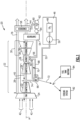
- Figure 1 schematically illustrates an example propulsion system 20 that includes an air separation system 66 that utilizes cryogenic fuel to transform a portion of oxygen of an inlet airflow into liquid oxygen.
- the liquid oxygen is utilized to generate an oxygen enriched flow that is injected into a combustor. Separation of oxygen from the inlet airflow further provides a nitrogen enriched stream that is utilized for cooling and for fuel tank inerting.
- the additional quantities of oxygen provided by oxygen enriched flows increase combustion capacity.
- the example propulsion system 20 includes a fan section 24 driven by a core engine 22.
- the core engine 22 includes a compressor section 26, a combustor section 28 and the turbine section 30 disposed along an engine longitudinal axis A.
- the fan section 24 drives inlet airflow 42 along a bypass flow path B, while the compressor section 26 draws air in along a core flow path C.
- the inlet airflow 42 is compressed and communicated to the combustor section 28 where the compressed core airflow 40 is mixed with a flow 70 and ignited to generate an exhaust gas flow 44.
- the exhaust gas flow 44 expands through the turbine section 30 where energy is extracted to generate a mechanical power output utilized to drive the fan section 24 and the compressor section 26.
- the compressor section 26 includes a low pressure compressor (LPC) 32 and a high pressure compressor (HPC) 34.
- the turbine section 30 includes a high pressure turbine (HPT) 36 and a low pressure turbine (LPT) 38.
- a fuel system 46 having at least a fuel tank 48 and a fuel pump 50 provides a fuel flow 52 to the combustor 28.
- the example fuel system 46 is configured to provide a cryogenic fuel such as liquid hydrogen (LH 2 ).
- LH 2 liquid hydrogen
- hydrogen is disclosed by way of example, other cryogenic fuels could be utilized and are within the contemplation of this disclosure.
- An evaporator system 54 and condenser 58 are disposed downstream of the turbine section 30 and receive the exhaust gas flow 44.
- the evaporator system 54 utilizes thermal energy from the exhaust gas flow 44 to generate a steam flow 56 from water 60 extracted by the condenser 58.
- the condenser 58 cools the exhaust gas flow 44 to extract water that is gathered in a tank 62 and pressurized by a pump 64.
- a cooling ram air flow 76 is used as the cold sink.
- Other cold sink flows may be utilized to cool the exhaust gas flow 44 within the condenser 58 and are within the contemplation and scope of this disclosure.
- the steam flow 56 from the evaporator 54 is injected into the core flow path C at or upstream of the combustor 28 and increases mass flow through the turbine section 30 and thereby increase engine power and efficiency.
- the propulsion system 20 has an increased power output from the injected steam 56 due to an increasing mass flow through the turbine section 30 without a corresponding increase in work from the compressor section 26.
- the steam flow 56 is shown as being injected into the combustor 28, the steam flow 56 may be injected at other locations along the core flow path C and remain within the contemplation and scope of this disclosure.
- the liquid hydrogen fuel is stored at cryogenic temperatures below about 60 °K (-213 °C).
- the cryogenic temperature of the fuel flow 52 is utilized as a cold sink to separate oxygen from an airflow 74 in an air separation system 66.
- the example air separation system 66 provides thermal communication between the fuel flow 52 and an airflow 74.
- the airflow 74 is drawn from a portion of the compressor section 26 and is therefore at an elevated pressure.
- the airflow 74 in one disclosed embodiment is drawn from a location between the LPC 32 and the HPC 34. However, the airflow 74 may be drawn from any location in the compressor section 26.
- the airflow 74 may be drawn from another source such as the bypass flow passage B, inlet airflow 42 or air obtained at ambient temperatures and pressures.
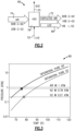
- the inlet airflow 74 includes oxygen and nitrogen in gas form. Oxygen is transformed to a liquid at temperatures below about 80 °K (-195 °C) at pressures below about 1 atmosphere as shown in graph 80 ( Figure 3 ).
- the cryogenic fuel flow 52 liquifies oxygen in the airflow 74 to enable separation from other components in the inlet airflow.
- the separated oxygen may initially be in a liquid form, the oxygen flow will be transformed into a gas form prior to injection in the combustor. Moreover, as the separated oxygen is communicated throughout the engine, the mixture of liquid and gas forms will change depending on the specific conditions in any location.
- the separated oxygen generates an enhanced oxygen flow 68 that may include both liquid oxygen and gaseous oxygen depending on relative temperatures and pressures.
- the oxygen enhanced flow 68 that is transformed into a gaseous flow oxygen enhanced for injection into the combustor 28 to further facilitate combustion.
- Fuel flow 70 exhausted from the air separation system 66 is in a gas form. The fuel flow 70 is communicated to the combustor 28 and mixed with the oxygen enhanced flow 68 to generate the exhaust gas flow 44.
- the use of the oxygen enhanced flow 68 reduces a percentage of nitrogen that is communicated to the combustor.
- a mass flow of nitrogen entering the combustor is less than 3.7 lb./s Nitrogen for each 1 lb./s oxygen entering the combustor.
- the amount of oxygen separated from the airflow may be controlled by controlling either the flow of incoming air or of the cryogenic fuel flow 52 into the separator 66. Moreover, an accumulator may be provided that stores some quantity of separated oxygen to provide a buffer to supplement operational conditions where the separation of oxygen from the airflow may not be sufficient to meet all demands.
- the control of the respective flows may be based on demand, the current cooling capacity of the cryogenic fuel flow or other operational conditions that affect separation.
- a ratio of airflow to the cryogenic fuel flow 52 may be controlled to tailor separation to operation specific demands.
- the saturation temperature of oxygen is higher than that of nitrogen at the mixing ratio of air. Accordingly, a portion of the oxygen is liquified before nitrogen within the inlet airflow 74 also becomes liquified. If only a part of the air is liquefied, that liquid will be enriched in oxygen relative to the other part. Either by selective liquification or other form of separation, the air separation system 66 produces both an oxygen enriched stream 68 and a nitrogen enriched stream 72.
- the nitrogen enriched stream 72 is communicated to cooling systems 82 in the core engine 22 to facilitate cooling. Additionally, the nitrogen enriched stream 72 may be utilized in a fuel tank inerting system 84. In each case, the nitrogen enriched stream is communicated away from the core flow and the combustion process.
- the air separation system 66 includes a heat exchanger 78 that provides for thermal communication between the fuel flow 52 and the inlet airflow 74.
- the heat exchanger 78, and thereby the air separation system 66 may be located at various locations relative to the core engine 22 that facilitate communication of the inlet airflow 74 and fuel flow 52.
- the outgoing fuel flow 70 may be routed to other heat exchangers for cooling.
- FIG. 4 another air separation system 86 is schematically shown and includes a recuperation heat exchanger 88.
- the recuperation heat exchanger 88 precools the inlet airflow 74 prior to cooling by the fuel flow 52 in the heat exchanger 78. Additionally, heat input into the inlet airflow 74 within the compressor section 26 is recovered and used to transform the separated LOX stream 68 into a gaseous oxygen flow 94 prior to injection into the combustor 28.
- a nitrogen enriched stream 72 and an oxygen enhanced stream 68 separated in the heat exchanger 78 are communicated to the recuperation heat exchanger 88 to precool the inlet airflow 74.
- the oxygen enhanced stream 68 is heated in the recuperation heat exchanger 88 and exhausted as the gaseous oxygen flow 94, which is communicated to the combustor 28.
- the nitrogen enriched stream 92 exhausted from the recuperation heat exchanger 88 is heated but is still provided at a temperature useful in the cooling system 82 and the fuel tank inerting system 84. Accordingly, the recuperation heat exchanger 88 recovers some cooling capacity from the products of air separation to increase engine the quantity of oxygen that can be separated.
- FIG. 5 another example air separation system 96 is schematically shown and includes a gaseous fuel turboexpander 104 and an oxygen gas turboexpander 106.
- the turboexpanders 104, 106 recapture energy from heating and cooling of the liquid fuel and oxygen enhanced stream.
- the inlet airflow 74 is precooled in a recuperation heat exchanger 98 by the oxygen enhanced stream 68 and the nitrogen-enriched flow 72 from the first heat exchanger 100.
- the liquid fuel flow 52 is pre-pressurized by a fuel pump 112 before entering the first heat exchanger 100 and exhausted after accepting heat from the inlet airflow 74 as a gaseous fuel flow 108.
- the gaseous fuel flow 108 is expanded through the fuel turboexpander 104 and exhausted as a cooled gaseous fuel flow 110.
- the fuel turboexpander 104 generates shaft power 124 that may be utilized to drive accessory devices such as for example, a pump, an electric motor and a hydraulic actuator.
- the cooled gaseous fuel flow 110 is communicated through a second heat exchanger to further pre-cool the inlet airflow 74.
- the exhausted gas flow 122 is communicated to the combustor 28 for combustion and generation of the exhaust gas flow 44.
- the oxygen enhanced flow 68 from the first heat exchanger 100 is pressurized in an oxygen pump 114 and communicated to the recuperation heat exchanger 98.
- the oxygen enhanced flow 68 accepts heat from the inlet airflow 74 in the recuperation heat exchanger 98 and is exhausted as an oxygen-enriched gas flow 116.
- the oxygen-enriched gas flow 116 is expanded through the oxygen turboexpander 106 to recover heat energy and generates a cooled oxygen-enriched gas flow 118.
- the turboexpander 106 generates shaft power 126 that may be utilized to drive accessory components and devices.
- the cooled oxygen-enriched gas flow 118 is reheated in the recuperation heat exchanger 98 to generate a heated oxygen-enriched flow 102.
- the heated oxygen-enriched flow 102 is communicated to the combustor 28 to facilitate combustion.
- the fuel flow 122 and the oxygen flow 120 may be communicated through additional heat exchangers and turboexpanders before injection into the combustor 28 to extract and recover any additional energy and/or cool other engine systems. While this embodiment shows several heat exchangers in series arrangement, alternate embodiments with the heat exchangers cooling portions of the inlet airflow 74 in parallel also remain within the contemplation and scope of this disclosure.
- FIG. 6 another example propulsion system 130 is schematically shown and includes a core engine 132 having a secondary combustor 150 where an oxygen enriched flow 158 is injected to support combustion.
- the example turbine engine 130 includes a compressor section 136, combustor 28 and a turbine section 140.
- the compressor section 136 includes an LPC 32, an HPC 34 and an intercooling system 154.
- the turbine section 140 includes an HPT 36, LPT 38 and the secondary combustor 150.
- the evaporator 54 and condenser 58 operate as previously described to generate a steam flow 56 injected into the combustor 28. In the described embodiment, steam flow 56 is communicated to the combustor 28. However, it is within the contemplation of this disclosure to additionally inject steam flow 56 into the secondary combustor 150.
- the air separator system 152 may be configured according to any previously described embodiment and separates the inlet airflow 74 into an oxygen enhanced stream 158 and a nitrogen-enriched stream 156.
- the liquid fuel flow 52 provides the cold sink that cools the inlet airflow 74 to temperatures needed to liquify the oxygen and generate the oxygen enhanced stream 158.
- the combustor 28 may operate at near stoichiometric conditions and therefore leave insufficient oxidant in the exhaust gas flow 44 to facilitate combustion in the secondary combustor 150. A portion of the oxygen enhanced stream 158 is therefore communicated to the secondary combustor 150 to support combustion.
- the fuel flow 160 exhausted from the air separator 152 is in a gaseous form and is communicated to both combustors 28, 150 for combustion.
- the example core engine 132 includes the intercooling system 154 that utilizes the nitrogen-enriched stream 156 to cool core airflow in the compressor section 136.
- the intercooling system 154 cools the core airflow between the LPC 32 and the HPC 34.
- the intercooling system 154 may provide air cooling at other locations within the compressor section 136 and remain within the contemplation and scope of this disclosure.
- the nitrogen-enriched flow 156 is exhausted into the ambient environment from the intercooling system 154.
- the nitrogen-enriched flow 156 may be communicated to provide cooling or fuel tank inerting.
- the example propulsion systems utilized cryogenic fuel to generate an oxygen-enriched flow that increases the amount of available oxygen to support combustion.
Landscapes
- Engineering & Computer Science (AREA)
- Mechanical Engineering (AREA)
- General Engineering & Computer Science (AREA)
- Chemical & Material Sciences (AREA)
- Combustion & Propulsion (AREA)
- Physics & Mathematics (AREA)
- Thermal Sciences (AREA)
- Health & Medical Sciences (AREA)
- Emergency Medicine (AREA)
- Chemical Kinetics & Catalysis (AREA)
- General Chemical & Material Sciences (AREA)
- Separation By Low-Temperature Treatments (AREA)
Abstract
A turbine engine assembly includes a compressor section (26, 136) where an inlet airflow is compressed, a cryogenic fuel system (46) for generating flow of cryogenic fuel, an air separation system (66, 96) where an airflow is placed in thermal communication with a portion of the flow of cryogenic fuel for generating an enhanced oxygen flow (68). In a combustor section (28), the compressed inlet airflow and a portion of the enhanced oxygen flow (68) is mixed with fuel and ignited to generate an exhaust gas flow (44) that is communicated through a core flow path (C) to a turbine section (30, 140) where expansion of the exhaust gas flow (44) is utilized to generate a mechanical power output. Water is extracted from the exhaust gas flow (44) in condenser (58) transformed into a steam flow (56) for injection into the core flow path (C) in an evaporator system (54).
Description
- The present invention relates generally to an aircraft propulsion system that utilizes a cryogenic fuel to liquify a portion of oxygen from an airflow.
- Reduction and/or elimination of carbon emissions generated by aircraft operation is a stated goal of aircraft manufacturers and airline operators. Turbine engines compress incoming core airflow, mix the compressed airflow with fuel that is ignited in a combustor to generate an exhaust gas flow. Steam injection can provide improved engine efficiencies and power density. However, extracting power from steam reduces the amount of air needed to be a working fluid. At high steam-air ratios, power is limited by the amount of oxygen available for combustion rather than turbine temperature. Cryogenic fuels provide an available cold sink that may present opportunities for integration into various engine systems and provide a means of improving engine efficiency not present in conventional turbine engine architectures.
- A turbine engine assembly according to an example of the present invention includes, among other possible things, a compressor section where an inlet airflow is compressed, a cryogenic fuel system for generating flow of cryogenic fuel, an air separation system where an airflow is placed in thermal communication with a portion of the flow of cryogenic fuel for generating an enhanced oxygen flow, a combustor section where the compressed inlet airflow and a portion of the enhanced oxygen flow is mixed with fuel and ignited to generate an exhaust gas flow that is communicated through a core flow path, a turbine section where expansion of the exhaust gas flow is utilized to generate a mechanical power output, a condenser where water is extracted from the exhaust gas flow, and an evaporator system where thermal energy from the exhaust gas flow is utilized to transform water extracted from the exhaust gas flow into a steam flow for injection into the core flow path.
- In an embodiment of the above, the air separation system is configured to receive a portion of airflow from the compressor section.
- In an embodiment according to any of the previous embodiments, the air separation system is configured to receive the airflow from an ambient environment at ambient temperature and pressure.
- In an embodiment according to any of the previous embodiments, the air separation system generates a nitrogen enriched flow that is communicated away from the core flow path through the turbine section.
- In an embodiment according to any of the previous embodiments, the nitrogen enriched flow is directed to cool a portion of the compressor section.
- In an embodiment according to any of the previous embodiments, a secondary combustor is disposed downstream of at least a portion of the turbine section, wherein a portion of the enhanced oxygen flow is communicated to the secondary combustor.
- In an embodiment according to any of the previous embodiments, the air separator comprises a first heat exchanger disposed outside of a core flow path, the heat exchanger configured to communicate the flow of cryogenic fuel with a flow of air.
- In an embodiment according to any of the previous embodiments, a recuperation heat exchanger is included where an enhanced oxygen flow and a nitrogen enriched gas (or flow) are placed in thermal communication with the flow of air.
- In an embodiment according to any of the previous embodiments, at least one recuperation turboexpander is included and is driven by an enhanced oxygen flow exhausted from the recuperation heat exchanger.
- In an embodiment according to any of the previous embodiments, at least one recuperation turboexpander is driven by a gaseous flow of cryogenic fuel exhausted from the first heat exchanger.
- An aircraft propulsion system according to another example of the present invention includes, among other possible things, a core engine configured to generate an exhaust gas flow, the core engine including a core flow path through a compressor section, a combustor section and a turbine section, a cryogenic fuel system configured to generate flow of cryogenic fuel, an air separation system where an airflow is placed in thermal communication with a portion of the flow cryogenic fuel for liquifying a portion of oxygen from the airflow to generate an enhanced oxygen flow. A portion of the enhanced oxygen flow is injected into the combustor section. The system further includes a condenser where water is extracted from the exhaust gas flow, an evaporator system where thermal energy from the exhaust gas flow is utilized to transform water extracted from the exhaust gas flow into a steam flow for injection into the core flow path.
- In an embodiment of the above, the air separation system is configured to receive a portion of airflow from the compressor section.
- In an embodiment according to any of the previous embodiments, the air separation system is configured to receive the airflow from an ambient environment at ambient temperature and pressure.
- In an embodiment according to any of the previous embodiments, a secondary combustor is disposed downstream of at least a portion of the turbine section and a portion of the enhanced oxygen flow is communicated to the secondary combustor.
- In an embodiment according to any of the previous embodiments, a recuperation system where at least one of an enhanced oxygen flow and a nitrogen enriched gas (or flow) are placed in thermal communication with the flow of air for precooling before communication into the air separation system.
- In an embodiment according to any of the previous embodiments, the air separation system generates a nitrogen enriched flow that is communicated away from the core flow path through the turbine section.
- A method of operating a gas turbine engine according to another example of the present invention includes, among other possible things, generating a flow of cryogenic fuel, separating oxygen from an airflow by liquifying oxygen through cooling with the flow cryogenic fuel to generate an enhanced oxygen flow, generating an exhaust gas flow in a combustor with a portion of the cryogenic fuel flow and the enhanced oxygen flow, expanding the gas flow through a turbine section and generating a mechanical power output, extracting water from the exhaust gas flow in a condenser, and transforming the water flow to a steam flow with heat from the exhaust gas flow in an evaporator system and injecting a portion of the steam flow into the combustor.
- An embodiment of the above includes separating a nitrogen enriched gas flow from the airflow and routing the nitrogen enriched gas flow away from a core flow path.
- An embodiment according to any of the previous embodiments includes injecting a portion of the enhanced oxygen flow into a secondary combustor and generating a second exhaust gas flow that is expanded through the turbine section to generate mechanical power.
- An embodiment according to any of the previous embodiments includes controlling generation of the oxygen enhanced flow by adjusting a ratio of a flow of cryogenic fuel relative to the airflow communicated to an air separator.
- Although the different examples have the specific components shown in the illustrations, embodiments of this invention are not limited to those particular combinations. It is possible to use some of the components or features from one of the examples in combination with features or components from another one of the examples.
- These and other features disclosed herein can be best understood from the following specification and drawings, the following of which is a brief description.
-
-
Figure 1 is a schematic view of an example aircraft propulsion system embodiment. -
Figure 2 is a schematic cross-sectional view of another example aircraft propulsion system embodiment. -
Figure 3 is a graph illustrating relative saturation points of oxygen and nitrogen. -
Figure 4 is a schematic view of an example air separation system embodiment. -
Figure 5 is a schematic view of another example air separation system embodiment. -
Figure 6 is a schematic view of another example aircraft propulsion system embodiment. -
Figure 1 schematically illustrates anexample propulsion system 20 that includes anair separation system 66 that utilizes cryogenic fuel to transform a portion of oxygen of an inlet airflow into liquid oxygen. The liquid oxygen is utilized to generate an oxygen enriched flow that is injected into a combustor. Separation of oxygen from the inlet airflow further provides a nitrogen enriched stream that is utilized for cooling and for fuel tank inerting. The additional quantities of oxygen provided by oxygen enriched flows increase combustion capacity. - The
example propulsion system 20 includes afan section 24 driven by acore engine 22. Thecore engine 22 includes acompressor section 26, acombustor section 28 and theturbine section 30 disposed along an engine longitudinal axis A. Thefan section 24 drivesinlet airflow 42 along a bypass flow path B, while thecompressor section 26 draws air in along a core flow path C. Theinlet airflow 42 is compressed and communicated to thecombustor section 28 where thecompressed core airflow 40 is mixed with aflow 70 and ignited to generate anexhaust gas flow 44. Theexhaust gas flow 44 expands through theturbine section 30 where energy is extracted to generate a mechanical power output utilized to drive thefan section 24 and thecompressor section 26. Thecompressor section 26 includes a low pressure compressor (LPC) 32 and a high pressure compressor (HPC) 34. Theturbine section 30 includes a high pressure turbine (HPT) 36 and a low pressure turbine (LPT) 38. - Although an example engine architecture is disclosed by way of example, other turbine engine architectures are within the contemplation and scope of this disclosure. Moreover, although the disclosed non-limiting embodiment depicts a turbofan turbine engine, it should be understood that the concepts described herein are not limited to use with turbofans as the teachings may be applied to other types of turbine engine architectures. Additionally, the features of this disclosure may be applied to other engine configurations utilized to generate shaft power.
- A
fuel system 46 having at least afuel tank 48 and afuel pump 50 provides afuel flow 52 to thecombustor 28. Theexample fuel system 46 is configured to provide a cryogenic fuel such as liquid hydrogen (LH2). Although hydrogen is disclosed by way of example, other cryogenic fuels could be utilized and are within the contemplation of this disclosure. - An
evaporator system 54 andcondenser 58 are disposed downstream of theturbine section 30 and receive theexhaust gas flow 44. Theevaporator system 54 utilizes thermal energy from theexhaust gas flow 44 to generate asteam flow 56 fromwater 60 extracted by thecondenser 58. - The
condenser 58 cools theexhaust gas flow 44 to extract water that is gathered in atank 62 and pressurized by apump 64. In one disclosed example embodiment, a coolingram air flow 76 is used as the cold sink. Other cold sink flows may be utilized to cool theexhaust gas flow 44 within thecondenser 58 and are within the contemplation and scope of this disclosure. - The
steam flow 56 from theevaporator 54 is injected into the core flow path C at or upstream of thecombustor 28 and increases mass flow through theturbine section 30 and thereby increase engine power and efficiency. Thepropulsion system 20 has an increased power output from the injectedsteam 56 due to an increasing mass flow through theturbine section 30 without a corresponding increase in work from thecompressor section 26. Although thesteam flow 56 is shown as being injected into thecombustor 28, thesteam flow 56 may be injected at other locations along the core flow path C and remain within the contemplation and scope of this disclosure. - The liquid hydrogen fuel is stored at cryogenic temperatures below about 60 °K (-213 °C). The cryogenic temperature of the
fuel flow 52 is utilized as a cold sink to separate oxygen from anairflow 74 in anair separation system 66. The exampleair separation system 66 provides thermal communication between thefuel flow 52 and anairflow 74. In one example embodiment, theairflow 74 is drawn from a portion of thecompressor section 26 and is therefore at an elevated pressure. Theairflow 74 in one disclosed embodiment is drawn from a location between theLPC 32 and theHPC 34. However, theairflow 74 may be drawn from any location in thecompressor section 26. Moreover, theairflow 74 may be drawn from another source such as the bypass flow passage B,inlet airflow 42 or air obtained at ambient temperatures and pressures. - Referring to
Figures 2 and 3 , with continued reference toFigure 1 , theinlet airflow 74 includes oxygen and nitrogen in gas form. Oxygen is transformed to a liquid at temperatures below about 80 °K (-195 °C) at pressures below about 1 atmosphere as shown in graph 80 (Figure 3 ). Thecryogenic fuel flow 52 liquifies oxygen in theairflow 74 to enable separation from other components in the inlet airflow. - Although the separated oxygen may initially be in a liquid form, the oxygen flow will be transformed into a gas form prior to injection in the combustor. Moreover, as the separated oxygen is communicated throughout the engine, the mixture of liquid and gas forms will change depending on the specific conditions in any location.
- The separated oxygen generates an enhanced
oxygen flow 68 that may include both liquid oxygen and gaseous oxygen depending on relative temperatures and pressures. The oxygen enhancedflow 68 that is transformed into a gaseous flow oxygen enhanced for injection into thecombustor 28 to further facilitate combustion.Fuel flow 70 exhausted from theair separation system 66 is in a gas form. Thefuel flow 70 is communicated to thecombustor 28 and mixed with the oxygen enhancedflow 68 to generate theexhaust gas flow 44. - In one example embodiment, the use of the oxygen enhanced
flow 68 reduces a percentage of nitrogen that is communicated to the combustor. In one example, a mass flow of nitrogen entering the combustor is less than 3.7 lb./s Nitrogen for each 1 lb./s oxygen entering the combustor. - The amount of oxygen separated from the airflow may be controlled by controlling either the flow of incoming air or of the
cryogenic fuel flow 52 into theseparator 66. Moreover, an accumulator may be provided that stores some quantity of separated oxygen to provide a buffer to supplement operational conditions where the separation of oxygen from the airflow may not be sufficient to meet all demands. The control of the respective flows may be based on demand, the current cooling capacity of the cryogenic fuel flow or other operational conditions that affect separation. A ratio of airflow to thecryogenic fuel flow 52 may be controlled to tailor separation to operation specific demands. - The saturation temperature of oxygen is higher than that of nitrogen at the mixing ratio of air. Accordingly, a portion of the oxygen is liquified before nitrogen within the
inlet airflow 74 also becomes liquified. If only a part of the air is liquefied, that liquid will be enriched in oxygen relative to the other part. Either by selective liquification or other form of separation, theair separation system 66 produces both an oxygen enrichedstream 68 and a nitrogen enrichedstream 72. The nitrogen enrichedstream 72 is communicated to coolingsystems 82 in thecore engine 22 to facilitate cooling. Additionally, the nitrogen enrichedstream 72 may be utilized in a fueltank inerting system 84. In each case, the nitrogen enriched stream is communicated away from the core flow and the combustion process. - In one disclosed example, the
air separation system 66 includes aheat exchanger 78 that provides for thermal communication between thefuel flow 52 and theinlet airflow 74. Theheat exchanger 78, and thereby theair separation system 66, may be located at various locations relative to thecore engine 22 that facilitate communication of theinlet airflow 74 andfuel flow 52. Moreover, theoutgoing fuel flow 70 may be routed to other heat exchangers for cooling. - Referring to
Figure 4 with continued reference toFigure 1 , anotherair separation system 86 is schematically shown and includes arecuperation heat exchanger 88. Therecuperation heat exchanger 88 precools theinlet airflow 74 prior to cooling by thefuel flow 52 in theheat exchanger 78. Additionally, heat input into theinlet airflow 74 within thecompressor section 26 is recovered and used to transform the separatedLOX stream 68 into agaseous oxygen flow 94 prior to injection into thecombustor 28. - In this example embodiment, a nitrogen enriched
stream 72 and an oxygen enhancedstream 68 separated in theheat exchanger 78 are communicated to therecuperation heat exchanger 88 to precool theinlet airflow 74. The oxygen enhancedstream 68 is heated in therecuperation heat exchanger 88 and exhausted as thegaseous oxygen flow 94, which is communicated to thecombustor 28. The nitrogen enrichedstream 92 exhausted from therecuperation heat exchanger 88 is heated but is still provided at a temperature useful in thecooling system 82 and the fueltank inerting system 84. Accordingly, therecuperation heat exchanger 88 recovers some cooling capacity from the products of air separation to increase engine the quantity of oxygen that can be separated. - Referring to
Figure 5 , another exampleair separation system 96 is schematically shown and includes agaseous fuel turboexpander 104 and anoxygen gas turboexpander 106. Theturboexpanders inlet airflow 74 is precooled in arecuperation heat exchanger 98 by the oxygen enhancedstream 68 and the nitrogen-enrichedflow 72 from thefirst heat exchanger 100. - The
liquid fuel flow 52 is pre-pressurized by afuel pump 112 before entering thefirst heat exchanger 100 and exhausted after accepting heat from theinlet airflow 74 as agaseous fuel flow 108. Thegaseous fuel flow 108 is expanded through thefuel turboexpander 104 and exhausted as a cooledgaseous fuel flow 110. The fuel turboexpander 104 generatesshaft power 124 that may be utilized to drive accessory devices such as for example, a pump, an electric motor and a hydraulic actuator. The cooledgaseous fuel flow 110 is communicated through a second heat exchanger to further pre-cool theinlet airflow 74. Theexhausted gas flow 122 is communicated to thecombustor 28 for combustion and generation of theexhaust gas flow 44. - The oxygen enhanced
flow 68 from thefirst heat exchanger 100 is pressurized in anoxygen pump 114 and communicated to therecuperation heat exchanger 98. The oxygen enhancedflow 68 accepts heat from theinlet airflow 74 in therecuperation heat exchanger 98 and is exhausted as an oxygen-enrichedgas flow 116. The oxygen-enrichedgas flow 116 is expanded through theoxygen turboexpander 106 to recover heat energy and generates a cooled oxygen-enrichedgas flow 118. Theturboexpander 106 generatesshaft power 126 that may be utilized to drive accessory components and devices. - In this example embodiment, the cooled oxygen-enriched
gas flow 118 is reheated in therecuperation heat exchanger 98 to generate a heated oxygen-enrichedflow 102. The heated oxygen-enrichedflow 102 is communicated to thecombustor 28 to facilitate combustion. Thefuel flow 122 and theoxygen flow 120 may be communicated through additional heat exchangers and turboexpanders before injection into thecombustor 28 to extract and recover any additional energy and/or cool other engine systems. While this embodiment shows several heat exchangers in series arrangement, alternate embodiments with the heat exchangers cooling portions of theinlet airflow 74 in parallel also remain within the contemplation and scope of this disclosure. - Referring to
Figure 6 , anotherexample propulsion system 130 is schematically shown and includes acore engine 132 having asecondary combustor 150 where an oxygen enrichedflow 158 is injected to support combustion. Theexample turbine engine 130 includes acompressor section 136,combustor 28 and aturbine section 140. Thecompressor section 136 includes anLPC 32, anHPC 34 and anintercooling system 154. Theturbine section 140 includes anHPT 36,LPT 38 and thesecondary combustor 150. Theevaporator 54 andcondenser 58 operate as previously described to generate asteam flow 56 injected into thecombustor 28. In the described embodiment,steam flow 56 is communicated to thecombustor 28. However, it is within the contemplation of this disclosure to additionally injectsteam flow 56 into thesecondary combustor 150. - The
air separator system 152 may be configured according to any previously described embodiment and separates theinlet airflow 74 into an oxygen enhancedstream 158 and a nitrogen-enrichedstream 156. Theliquid fuel flow 52 provides the cold sink that cools theinlet airflow 74 to temperatures needed to liquify the oxygen and generate the oxygen enhancedstream 158. - The
combustor 28 may operate at near stoichiometric conditions and therefore leave insufficient oxidant in theexhaust gas flow 44 to facilitate combustion in thesecondary combustor 150. A portion of the oxygen enhancedstream 158 is therefore communicated to thesecondary combustor 150 to support combustion. Thefuel flow 160 exhausted from theair separator 152 is in a gaseous form and is communicated to bothcombustors - The
example core engine 132 includes theintercooling system 154 that utilizes the nitrogen-enrichedstream 156 to cool core airflow in thecompressor section 136. In this disclosed example, theintercooling system 154 cools the core airflow between theLPC 32 and theHPC 34. However, theintercooling system 154 may provide air cooling at other locations within thecompressor section 136 and remain within the contemplation and scope of this disclosure. - The nitrogen-enriched
flow 156 is exhausted into the ambient environment from theintercooling system 154. The nitrogen-enrichedflow 156 may be communicated to provide cooling or fuel tank inerting. - Accordingly, the example propulsion systems utilized cryogenic fuel to generate an oxygen-enriched flow that increases the amount of available oxygen to support combustion.
- Although an example embodiment has been disclosed, a worker of ordinary skill in this art would recognize that certain modifications would come within the scope of this disclosure. For that reason, the following claims should be studied to determine the scope and content of this disclosure.
Claims (15)
- A turbine engine assembly comprising:a compressor section (26, 136) where an inlet airflow (42) is compressed;a cryogenic fuel system (46) for generating flow of cryogenic fuel (52);an air separation system (66, 96) where an airflow (74) is placed in thermal communication with a portion of the flow of cryogenic fuel (52) for generating an enhanced oxygen flow (68);a combustor section (28) where the compressed inlet airflow (74) and a portion of the enhanced oxygen flow (68) is mixed with fuel and ignited to generate an exhaust gas flow (44) that is communicated through a core flow path (C);a turbine section (30, 140) where expansion of the exhaust gas flow (44) is utilized to generate a mechanical power output;a condenser (58) where water is extracted from the exhaust gas flow (44); andan evaporator system (54) where thermal energy from the exhaust gas flow (44) is utilized to transform water extracted from the exhaust gas flow (44) into a steam flow (56) for injection into the core flow path (C).
- The turbine engine assembly as recited in claim 1, wherein the air separation system (66, 96) generates a nitrogen enriched flow (156, 72, 92) that is communicated away from the core flow path (C) through the turbine section (30, 140), optionally wherein the nitrogen enriched flow (156, 72, 92) is directed to cool a portion of the compressor section (26, 136).
- The turbine engine assembly as recited in claim 1 or 2, wherein the air separation system (66, 96) comprises a first heat exchanger (100) disposed outside of a or the core flow path (C), the first heat exchanger (100) configured to communicate the flow of cryogenic fuel (52) with a flow of air (74).
- The turbine engine assembly as recited in any preceding claim, further including a recuperation heat exchanger (98) where an enhanced oxygen flow (68) and a nitrogen enriched gas (72) are placed in thermal communication with a or the flow of air (74).
- The turbine engine assembly as recited in claim 4, further comprising at least one recuperation turboexpander (106) driven by an enhanced oxygen flow (116) exhausted from the recuperation heat exchanger (98).
- The turbine engine assembly as recited in claim 4 or 5, further comprising at least one recuperation turboexpander (104) driven by a gaseous flow of cryogenic fuel (108) exhausted from the first heat exchanger (100).
- An aircraft propulsion system comprising:a core engine (22, 132) configured to generate an exhaust gas flow (44), the core engine (22, 132) including a core flow path (C) through a compressor section (26, 136), a combustor section (28) and a turbine section (30, 140);a cryogenic fuel system (46) configured to generate flow of cryogenic fuel (52);an air separation system (66, 96) where an airflow (74) is placed in thermal communication with a portion of the flow of cryogenic fuel (52) for liquifying a portion of oxygen from the airflow (74) to generate an enhanced oxygen flow (68), wherein a portion of the enhanced oxygen flow (68) is injected into the combustor section (28);a condenser (58) where water is extracted from the exhaust gas flow (44); andan evaporator system (54) where thermal energy from the exhaust gas flow (44) is utilized to transform water extracted from the exhaust gas flow (44) into a steam flow (56) for injection into the core flow path (C).
- The turbine engine assembly or aircraft propulsion system of any preceding claim, wherein the air separation system (66, 96) is configured to receive a portion of airflow (74) from the compressor section (26, 136).
- The turbine engine assembly or aircraft propulsion system as recited in any preceding claim, wherein the air separation system (66, 96) is configured to receive the airflow (74) from an ambient environment at ambient temperature and pressure.
- The turbine engine assembly or aircraft propulsion system as recited in any preceding claim, further including a secondary combustor (150) disposed downstream of at least a portion of the turbine section (30, 140), wherein a portion of the enhanced oxygen flow (160) is communicated to the secondary combustor (150).
- The aircraft propulsion system as recited in any of claims 7 to 10, wherein:the aircraft propulsion system further includes a recuperation system where at least one of an or the enhanced oxygen flow (68) and an or the nitrogen enriched gas (72, 92) are placed in thermal communication with a or the flow of air (74) for precooling before communication into the air separation system (66, 96); and/orthe air separation system (66, 96) generates a or the nitrogen enriched flow (72, 92) that is communicated away from the core flow path (C) through the turbine section (30, 140).
- A method of operating a gas turbine engine, the method comprising:generating a flow of cryogenic fuel (52);separating oxygen from an airflow (74) by liquifying oxygen through cooling with the flow cryogenic fuel (52) to generate an enhanced oxygen flow (68);generating an exhaust gas flow (44) in a combustor (28) with a portion of the cryogenic fuel flow (52) and the enhanced oxygen flow (68);expanding the exhaust gas flow (44) through a turbine section (30, 140) and generating a mechanical power output;extracting water (60) from the exhaust gas flow (44) in a condenser (58); andtransforming the water flow (60) to a steam flow (56) with heat from the exhaust gas flow (44) in an evaporator system (54) and injecting a portion of the steam flow (56) into the combustor (28).
- The method as recited in claim 12, further comprising separating a nitrogen enriched gas flow (72, 92) from the airflow (74) and routing the nitrogen enriched gas flow (72, 92) away from a core flow path (C).
- The method as recited in claim 12 or 13, further comprising injecting a portion of the enhanced oxygen flow (68) into a secondary combustor (150) and generating a second exhaust gas flow (44) that is expanded through the turbine section (30, 140) to generate mechanical power.
- The method as recited in any of claims 12 to 14, further comprising controlling generation of the enhanced oxygen flow (68) by adjusting a ratio of a flow of cryogenic fuel (52) relative to the airflow (74) communicated to an air separator (152).
Applications Claiming Priority (1)
| Application Number | Priority Date | Filing Date | Title |
|---|---|---|---|
| US18/340,529 US20240426242A1 (en) | 2023-06-23 | 2023-06-23 | Cryogenic air separation enhanced gas turbine |
Publications (1)
| Publication Number | Publication Date |
|---|---|
| EP4481172A1 true EP4481172A1 (en) | 2024-12-25 |
Family
ID=91431453
Family Applications (1)
| Application Number | Title | Priority Date | Filing Date |
|---|---|---|---|
| EP24180300.6A Pending EP4481172A1 (en) | 2023-06-23 | 2024-06-05 | Cryogenic air separation enhanced gas turbine |
Country Status (2)
| Country | Link |
|---|---|
| US (1) | US20240426242A1 (en) |
| EP (1) | EP4481172A1 (en) |
Cited By (1)
| Publication number | Priority date | Publication date | Assignee | Title |
|---|---|---|---|---|
| US20250369393A1 (en) * | 2024-05-30 | 2025-12-04 | Rtx Corporation | Axial flow angled condenser arrangement for an aircraft propulsion system |
Families Citing this family (1)
| Publication number | Priority date | Publication date | Assignee | Title |
|---|---|---|---|---|
| US12479590B2 (en) * | 2024-03-29 | 2025-11-25 | General Electric Company | Turbine engine for an aircraft including a contrail mitigation system |
Citations (3)
| Publication number | Priority date | Publication date | Assignee | Title |
|---|---|---|---|---|
| US20030131582A1 (en) * | 2001-12-03 | 2003-07-17 | Anderson Roger E. | Coal and syngas fueled power generation systems featuring zero atmospheric emissions |
| US11603798B1 (en) * | 2022-02-11 | 2023-03-14 | Raytheon Technologies Corporation | Cryogenically assisted exhaust condensation |
| US11635022B1 (en) * | 2022-02-11 | 2023-04-25 | Raytheon Technologies Corporation | Reducing contrails from an aircraft powerplant |
Family Cites Families (10)
| Publication number | Priority date | Publication date | Assignee | Title |
|---|---|---|---|---|
| DE2413507A1 (en) * | 1974-03-20 | 1975-10-02 | Motoren Turbinen Union | GAS TURBINE FOR CRYOGENIC FUEL |
| US4378920A (en) * | 1980-07-15 | 1983-04-05 | The Boeing Company | Combustibly inert air supply system and method |
| US5406786A (en) * | 1993-07-16 | 1995-04-18 | Air Products And Chemicals, Inc. | Integrated air separation - gas turbine electrical generation process |
| WO1996007019A2 (en) * | 1994-08-31 | 1996-03-07 | Westinghouse Electric Corporation | A method of burning hydrogen in a gas turbine power plant |
| US7650744B2 (en) * | 2006-03-24 | 2010-01-26 | General Electric Company | Systems and methods of reducing NOx emissions in gas turbine systems and internal combustion engines |
| US7861509B2 (en) * | 2007-01-23 | 2011-01-04 | General Electric Company | Methods and systems for gas turbine syngas warm-up with low emissions |
| US20130186101A1 (en) * | 2012-01-24 | 2013-07-25 | General Electric Company | Method of using external fluid for cooling high temperature components of gas turbine for a process power plant |
| DE102021201629A1 (en) * | 2020-08-05 | 2022-02-10 | MTU Aero Engines AG | EXHAUST TREATMENT DEVICE FOR AN AIRCRAFT ENGINE |
| FR3122701B1 (en) * | 2021-05-10 | 2023-12-29 | Safran | System and method for supplying fuel to an aircraft turbomachine using fuel from a cryogenic tank |
| US12428991B2 (en) * | 2022-05-19 | 2025-09-30 | Rtx Corporation | Reverse flow hydrogen steam injected turbine engine |
-
2023
- 2023-06-23 US US18/340,529 patent/US20240426242A1/en active Pending
-
2024
- 2024-06-05 EP EP24180300.6A patent/EP4481172A1/en active Pending
Patent Citations (3)
| Publication number | Priority date | Publication date | Assignee | Title |
|---|---|---|---|---|
| US20030131582A1 (en) * | 2001-12-03 | 2003-07-17 | Anderson Roger E. | Coal and syngas fueled power generation systems featuring zero atmospheric emissions |
| US11603798B1 (en) * | 2022-02-11 | 2023-03-14 | Raytheon Technologies Corporation | Cryogenically assisted exhaust condensation |
| US11635022B1 (en) * | 2022-02-11 | 2023-04-25 | Raytheon Technologies Corporation | Reducing contrails from an aircraft powerplant |
Cited By (1)
| Publication number | Priority date | Publication date | Assignee | Title |
|---|---|---|---|---|
| US20250369393A1 (en) * | 2024-05-30 | 2025-12-04 | Rtx Corporation | Axial flow angled condenser arrangement for an aircraft propulsion system |
Also Published As
| Publication number | Publication date |
|---|---|
| US20240426242A1 (en) | 2024-12-26 |
Similar Documents
| Publication | Publication Date | Title |
|---|---|---|
| EP4481172A1 (en) | Cryogenic air separation enhanced gas turbine | |
| US12215622B1 (en) | Partial exhaust condensation intercooling | |
| US6276123B1 (en) | Two stage expansion and single stage combustion power plant | |
| US11920526B1 (en) | Inter-cooled preheat of steam injected turbine engine | |
| US12270333B2 (en) | Partial exhaust gas condensation with inverse Brayton control | |
| US12180893B2 (en) | Hydrogen steam injected turbine engine with turboexpander heat recovery | |
| US20240026816A1 (en) | Hydrogen-oxygen gas turbine engine | |
| US20240360788A1 (en) | Partial exhaust condensation with cryogenic assisted bottoming cycle | |
| US20240360786A1 (en) | Cryogenic assisted bottoming cycle | |
| EP4517059A1 (en) | Partial exhaust gas augmented condensation | |
| EP4471262A1 (en) | Aircraft propulsion system with cooling architecture for liquid hydrogen superconducting system | |
| US12529333B2 (en) | Partial exhaust condensation with cryogenic assisted bottoming cycle | |
| US20240141831A1 (en) | Hydrogen steam injected turbine engine with cooled cooling air | |
| EP4444997B1 (en) | Power generation and storage | |
| US12473858B2 (en) | Partial exhaust bottoming cycle | |
| US20240360791A1 (en) | Cryo-assisted bottoming cycle heat source sequencing | |
| EP4678893A1 (en) | Cryo-assisted bottoming cycle heat source sequencing | |
| EP4678891A2 (en) | Cryogenic assisted bottoming cycle | |
| US12601486B2 (en) | Hydrogen fuelled gas turbine engine | |
| EP4678887A1 (en) | Partial exhaust condensation with cryogenic assisted bottoming cycle | |
| US20260015969A1 (en) | Fuel cell exhaust condensation with turbomachinery water augmentation using cryogenic bottoming cycle |
Legal Events
| Date | Code | Title | Description |
|---|---|---|---|
| PUAI | Public reference made under article 153(3) epc to a published international application that has entered the european phase |
Free format text: ORIGINAL CODE: 0009012 |
|
| STAA | Information on the status of an ep patent application or granted ep patent |
Free format text: STATUS: THE APPLICATION HAS BEEN PUBLISHED |
|
| AK | Designated contracting states |
Kind code of ref document: A1 Designated state(s): AL AT BE BG CH CY CZ DE DK EE ES FI FR GB GR HR HU IE IS IT LI LT LU LV MC ME MK MT NL NO PL PT RO RS SE SI SK SM TR |
|
| STAA | Information on the status of an ep patent application or granted ep patent |
Free format text: STATUS: REQUEST FOR EXAMINATION WAS MADE |
|
| 17P | Request for examination filed |
Effective date: 20250625 |