EP4481165A1 - Gas turbine structure with structural reinforcement patterns - Google Patents
Gas turbine structure with structural reinforcement patterns Download PDFInfo
- Publication number
- EP4481165A1 EP4481165A1 EP24184106.3A EP24184106A EP4481165A1 EP 4481165 A1 EP4481165 A1 EP 4481165A1 EP 24184106 A EP24184106 A EP 24184106A EP 4481165 A1 EP4481165 A1 EP 4481165A1
- Authority
- EP
- European Patent Office
- Prior art keywords
- wall portion
- dimensional shape
- instances
- end portions
- component
- Prior art date
- Legal status (The legal status is an assumption and is not a legal conclusion. Google has not performed a legal analysis and makes no representation as to the accuracy of the status listed.)
- Pending
Links
Images



Classifications
-
- F—MECHANICAL ENGINEERING; LIGHTING; HEATING; WEAPONS; BLASTING
- F01—MACHINES OR ENGINES IN GENERAL; ENGINE PLANTS IN GENERAL; STEAM ENGINES
- F01D—NON-POSITIVE DISPLACEMENT MACHINES OR ENGINES, e.g. STEAM TURBINES
- F01D25/00—Component parts, details, or accessories, not provided for in, or of interest apart from, other groups
- F01D25/24—Casings; Casing parts, e.g. diaphragms, casing fastenings
-
- F—MECHANICAL ENGINEERING; LIGHTING; HEATING; WEAPONS; BLASTING
- F01—MACHINES OR ENGINES IN GENERAL; ENGINE PLANTS IN GENERAL; STEAM ENGINES
- F01D—NON-POSITIVE DISPLACEMENT MACHINES OR ENGINES, e.g. STEAM TURBINES
- F01D21/00—Shutting-down of machines or engines, e.g. in emergency; Regulating, controlling, or safety means not otherwise provided for
- F01D21/04—Shutting-down of machines or engines, e.g. in emergency; Regulating, controlling, or safety means not otherwise provided for responsive to undesired position of rotor relative to stator or to breaking-off of a part of the rotor, e.g. indicating such position
- F01D21/045—Shutting-down of machines or engines, e.g. in emergency; Regulating, controlling, or safety means not otherwise provided for responsive to undesired position of rotor relative to stator or to breaking-off of a part of the rotor, e.g. indicating such position special arrangements in stators or in rotors dealing with breaking-off of part of rotor
-
- F—MECHANICAL ENGINEERING; LIGHTING; HEATING; WEAPONS; BLASTING
- F05—INDEXING SCHEMES RELATING TO ENGINES OR PUMPS IN VARIOUS SUBCLASSES OF CLASSES F01-F04
- F05D—INDEXING SCHEME FOR ASPECTS RELATING TO NON-POSITIVE-DISPLACEMENT MACHINES OR ENGINES, GAS-TURBINES OR JET-PROPULSION PLANTS
- F05D2220/00—Application
- F05D2220/30—Application in turbines
- F05D2220/32—Application in turbines in gas turbines
-
- F—MECHANICAL ENGINEERING; LIGHTING; HEATING; WEAPONS; BLASTING
- F05—INDEXING SCHEMES RELATING TO ENGINES OR PUMPS IN VARIOUS SUBCLASSES OF CLASSES F01-F04
- F05D—INDEXING SCHEME FOR ASPECTS RELATING TO NON-POSITIVE-DISPLACEMENT MACHINES OR ENGINES, GAS-TURBINES OR JET-PROPULSION PLANTS
- F05D2230/00—Manufacture
- F05D2230/20—Manufacture essentially without removing material
-
- F—MECHANICAL ENGINEERING; LIGHTING; HEATING; WEAPONS; BLASTING
- F05—INDEXING SCHEMES RELATING TO ENGINES OR PUMPS IN VARIOUS SUBCLASSES OF CLASSES F01-F04
- F05D—INDEXING SCHEME FOR ASPECTS RELATING TO NON-POSITIVE-DISPLACEMENT MACHINES OR ENGINES, GAS-TURBINES OR JET-PROPULSION PLANTS
- F05D2230/00—Manufacture
- F05D2230/50—Building or constructing in particular ways
- F05D2230/54—Building or constructing in particular ways by sheet metal manufacturing
-
- F—MECHANICAL ENGINEERING; LIGHTING; HEATING; WEAPONS; BLASTING
- F05—INDEXING SCHEMES RELATING TO ENGINES OR PUMPS IN VARIOUS SUBCLASSES OF CLASSES F01-F04
- F05D—INDEXING SCHEME FOR ASPECTS RELATING TO NON-POSITIVE-DISPLACEMENT MACHINES OR ENGINES, GAS-TURBINES OR JET-PROPULSION PLANTS
- F05D2240/00—Components
- F05D2240/90—Mounting on supporting structures or systems
-
- F—MECHANICAL ENGINEERING; LIGHTING; HEATING; WEAPONS; BLASTING
- F05—INDEXING SCHEMES RELATING TO ENGINES OR PUMPS IN VARIOUS SUBCLASSES OF CLASSES F01-F04
- F05D—INDEXING SCHEME FOR ASPECTS RELATING TO NON-POSITIVE-DISPLACEMENT MACHINES OR ENGINES, GAS-TURBINES OR JET-PROPULSION PLANTS
- F05D2250/00—Geometry
- F05D2250/20—Three-dimensional
-
- F—MECHANICAL ENGINEERING; LIGHTING; HEATING; WEAPONS; BLASTING
- F05—INDEXING SCHEMES RELATING TO ENGINES OR PUMPS IN VARIOUS SUBCLASSES OF CLASSES F01-F04
- F05D—INDEXING SCHEME FOR ASPECTS RELATING TO NON-POSITIVE-DISPLACEMENT MACHINES OR ENGINES, GAS-TURBINES OR JET-PROPULSION PLANTS
- F05D2250/00—Geometry
- F05D2250/60—Structure; Surface texture
Definitions
- This invention relates to structures for use in gas turbine engines, and more particularly to a structure with a structural reinforcement pattern.
- Portions of aircraft engines are composed of light structures, which are made of thin sheet metal. While such existing structures may be suitable for their intended purposes, improvements to such structures are always desirable.
- a component configured for use in a gas turbine engine, including: a wall portion formed from sheet metal and extending between two end portions, the wall portion being stamped with a plurality of instances of a pre-defined three dimensional shape structured to increase a stiffness of the wall portion in a direction normal to the wall portion, each instance of the plurality of instances of the pre-defined three dimensional shape being orientated at 90 degrees with respect to each other adjacent instance of the plurality of instances, wherein the three dimensional shape has a pair of curved distal peripheral end portions that are at opposite ends of the three dimensional shape and each pair of curved distal peripheral end portions are connected to each other by a pair of opposing concave peripheral portions that curve towards each other at a mid-section.
- the wall portion is cylindrical in shape.
- the wall portion extends between two end portions that are ring shaped.
- the wall portion is conical in shape.
- the wall portion is a linear panel and is rectangular in shape.
- the component is a casing for the gas turbine engine.
- the wall portion is cylindrical in shape.
- the wall portion extends between two end portions that are ring shaped.
- the wall portion is conical in shape.
- a gas turbine engine comprising the component, in accordance with any of the above (or as claimed herein).
- a portion of a gas turbine engine including: a component, the component including a wall portion formed from sheet metal and extending between two end portions, the wall portion being stamped with a plurality of instances of a pre-defined three dimensional shape structured to increase a stiffness of the wall portion in a direction normal to the wall portion, each instance of the plurality of instances of the pre-defined three dimensional shape being orientated 90 degrees with respect to each other adjacent instance of the plurality of instances, wherein the three dimensional shape has a pair of curved distal peripheral end portions that are at opposite ends of the three dimensional shape and each pair of curved distal peripheral end portions are connected to each other by a pair of opposing concave peripheral portions that curve towards each other at a mid-section.
- the wall portion is cylindrical in shape.
- the wall portion is a linear panel and is rectangular in shape.
- the component is a casing for the gas turbine engine.
- the wall portion is cylindrical in shape and the wall portion extends between two end portions that are ring shaped.
- a method for forming a component configured for use in a gas turbine engine including: stamping a sheet metal with a plurality of instances of a pre-defined three dimensional shape structured to increase a stiffness of the in a direction normal to the sheet metal, each instance of the plurality of instances of the pre-defined three dimensional shape being orientated at 90 degrees with respect to each other adjacent instance of the plurality of instances, wherein the three dimensional shape has a pair of curved distal peripheral end portions that are at opposite ends of the three dimensional shape and the pair of curved distal peripheral end portions are connected to each other by a pair of opposing concave peripheral portions that curve towards each other at a mid-section; and forming a wall portion from the stamped sheet metal, the wall portion extending between two end portions.
- the wall portion extends between two end portions that are ring shaped.
- the wall portion is a linear panel and is rectangular in shape.
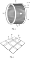
- FIG. 1 illustrates a component or casing 10 configured for use in a gas turbine engine.
- the casing 10 is cylindrical in shape and has a wall portion 12 extending between two end portions 14 and 16, which are ring shaped.
- a cylindrical wall portion 12 and ring shaped end portions 14 and 16 are illustrated, various embodiments of the present invention are contemplated for use with any other suitable structures including but not limited to, flat walls, cylinders or cones.
- the wall portion 12 is formed from a sheet metal material that is stamped with a plurality of unique shapes or a plurality of instances of a pre-defined three dimensional shape 18 that when stamped into the sheet metal provide three dimensional depressions in the sheet metal that increase the stiffness of the casing 10 in a direction normal to the wall portion 12 (illustrated by arrows 22).
- the pre-defined three dimensional shape 18 is structured to increase a stiffness of the wall portion 12 in a direction 22 normal to the wall portion 12, i.e. in the direction 22 of the thickness of the wall portion 12.
- the buckling capacity of the casing or component 10 is increased in the direction illustrated by arrows 20 due to the increased stiffness in the direction of arrows 22.
- the casing or component 10 is capable of supporting higher loads than a casing without any of the unique shapes or instances of the pre-defined three dimensional shape 18 stamped therein.
- the present invention is not limited to engine casings.
- the component 10 with the unique shapes or instances of the pre-defined three dimensional shape 18 may be any suitable component that would benefit from the stiffness and enhanced dynamic behavior provided when the unique shapes 18 are stamped therein.
- Non-limiting examples of the component 10 may includes a heat shield, structural brackets, supporting brackets, mounting brackets, mounts, shields, enclosures, casings, heat shields (heat barrier walls), some internal walls for supporting seals, any device covers and equivalents thereof anyone of which may be flat or have a three dimensional shape.
- the dynamic behavior of the wall portion 12 is improved and/or the ability of the wall portion 12 to carry lateral loads is increased.
- the three dimensional depressions of shapes 18 or instances of a pre-defined three dimensional shape 18 provide the aforementioned increase in the structural behavior of the casing or component 10.
- the shapes 18 or instances of a pre-defined three dimensional shape 18 are depressed into one surface of the wall portion 12 during a stamping process and the shapes 18 or instances of the pre-defined three dimensional shape 18 protrude from an opposite side or surface of the wall portion 12.
- the special shapes or instances of the pre-defined three dimensional shape 18 are stamped into the sheet metal to make it more rigid in certain directions.
- the three dimensional structure or the shape 18 or instances of the pre-defined three dimensional shape 18 generated by this method provides a significant increase of stiffness in a lateral direction of the sheet metal surface.
- the stamped structure can be created by making an isogrid or by stamping repeatable shapes following a certain pattern.
- the stamped shapes improve the lateral and bending stiffness of the sheet metal, which also increases the natural frequency of the structure made of stamped sheet metal relative to a flat or unstamped sheet metal structure.
- additional or higher loads can be carried directly by the stamped sheet metal. This means components can be mounted directly to the stamped sheathing, which eliminates the need for adding ribs resulting in lighter and more complex construction.
- the shapes 18 are a plurality of instances of a pre-defined three dimensional shape 18.
- the plurality of instances include a plurality of instances of a pre-defined three dimensional shape 18.
- the plurality of instances of the pre-defined three dimensional shape 18 being orientated 90 degrees with respect to each other adjacent instance of the plurality of instances of the pre-defined three dimensional shape 18. As illustrated in FIGS.
- each three dimensional shape 18 of the plurality of instances of the pre-defined three dimensional shape 18 has a pair of curved or circular distal peripheral end portions 24, 26 that are at opposite ends of the shape 18 and each of the curved or circular distal peripheral end portions 24, 26 are connected to each other by a pair of opposing concave or curved peripheral portions 28 that curve towards each other at a mid-section 29 of the pair of opposing concave or curved peripheral portions 28.
- peripheral portions of the shape 18 connecting the distal ends are concave with respect to the exterior of the shape.
- each of the shapes have rounded peripheral end portions connected by a concave curved peripheral portion.
- the plurality of instances of the pre-defined three dimensional shape 18 are generally the same or of the same configuration however and due to manufacturing tolerances, each instance of the plurality of instances of the pre-defined three dimensional shape 18 may not be exactly the same.
- the present invention is intended to cover instances of the pre-defined three dimensional shape 18 where due to manufacturing tolerances slight variances may occur.
- the present invention is also intended to cover instances of the pre-defined three dimensional shape 18 where the plurality of instances of the pre-defined three dimensional shape 18 are identical.
- a plurality of instances of portions of the three dimensional shape 18 are also provided at the periphery of the wall portion 12 where there is not enough material to support the entire configuration of the pre-defined three dimensional shape 18. It is also understood that the plurality of instances of portions of the three dimensional shape 18 are intended to cover instances of portions of the three dimensional shape 18 where there are slight variations due to the aforementioned manufacturing tolerances and/or instances of portions of the pre-defined three dimensional shape 18 where the instances of portions of the pre-defined three dimensional shape 18 are identical.
- FIGS. 3 and 4 an alternative casing or component 10 configured for use in a gas turbine engine is illustrated.
- the casing 10 is cylindrical in shape and has a wall portion 12 extending between two end portions 14 and 16, which are ring shaped.
- a cylindrical wall portion 12 and ring shaped end portions 14 and 16 are illustrated, various embodiments of the present invention are contemplated for use with any other suitable structures including but not limited to, flat walls, cylinders or cones or other configurations of the component 10 as mentioned above.
- the wall portion 12 is formed from a sheet metal material that is stamped with unique shapes 18 or a plurality of instances of a pre-defined three dimensional shape 18 that when stamped into the sheet metal increase the stiffness of the casing or component 10 in a direction normal to the wall portion 12 (illustrated by arrows 22).
- the buckling capacity of the casing or component 10 is increased in the direction illustrated by arrows 20 due to the increased stiffness in the direction of arrows 22.
- the dynamic behavior of the wall portion 12 is improved and/or the ability of the wall portion 12 to carry lateral loads is increased.
- the stamped shapes or the plurality of instances of the pre-defined three dimensional shape 18 are rectangles or squares 30 that are bounded by vertical walls 32.
- the wall portion 12 is formed from a sheet metal material that is stamped with unique shapes 18 or a plurality of instances of a pre-defined three dimensional shape 18 that when stamped into the sheet metal increase the stiffness of the casing or component 10 in a direction normal to the wall portion 12 (illustrated by arrows 22).
- the buckling capacity of the casing or component 10 is increased in the direction illustrated by arrows 20 due to the increased stiffness in the direction of arrows 22.
- the dynamic behavior of the wall portion 12 is also improved and/or the ability of the wall portion 12 to carry lateral loads is increased.
- the stamped shapes 18 or the plurality of instances of the pre-defined three dimensional shape 18 are diamond in shape.
- the shapes 18 may also be referred to as a rhombus or a parallelogram. These shapes are also formed by vertical walls 32.
- the shapes 18 or the plurality of instances of the pre-defined three dimensional shape 18 are triangular and the repeating pattern may be referred to as a series of rows of shapes 18 comprising a first row 34 of shapes 18 and a second row 36 of shapes 18, wherein the second row 36 is inverted with respect to the first row 34.
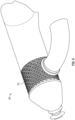
- FIG. 8 illustrates a portion of a gas turbine engine 40 with the casing or component 10 in accordance with the present invention.
- FIG. 9 is a generic representation of a component 10 having wall portions 12 with a plurality of shapes 18 or a plurality of instances of the pre-defined three dimensional shape 18 stamped therein using an isogrid pattern.
- the plurality of instances of the pre-defined three dimensional shape 18 are generally the same or of the same configuration however and due to manufacturing tolerances, each instance of the plurality of instances of the pre-defined three dimensional shape 18 may not be exactly the same.
- the present invention is intended to cover instances of the pre-defined three dimensional shape 18 where due to manufacturing tolerances slight variances may occur.
- the present invention is also intended to cover instances of the pre-defined three dimensional shape 18 where the plurality of instances of the pre-defined three dimensional shape 18 are identical.
- a plurality of instances of portions of the three dimensional shape 18 are also provided at the periphery of the wall portion 12 where there is not enough material to support the entire configuration of the pre-defined three dimensional shape 18. It is also understood that the plurality of instances of portions of the three dimensional shape 18 are intended to cover instances of portions of the three dimensional shape 18 where there are slight variations due to the aforementioned manufacturing tolerances and/or instances of portions of the pre-defined three dimensional shape 18 where the instances of portions of the pre-defined three dimensional shape 18 are identical.
Landscapes
- Engineering & Computer Science (AREA)
- Mechanical Engineering (AREA)
- General Engineering & Computer Science (AREA)
- Turbine Rotor Nozzle Sealing (AREA)
- Supercharger (AREA)
Abstract
A component (10) configured for use in a gas turbine engine, including: a wall portion (12) formed from sheet metal and extending between two end portions (14, 16), the wall portion (12) being stamped with a plurality of instances of a pre-defined three dimensional shape (18) structured to increase a stiffness of the wall portion (12) in a direction (22) normal to the wall portion (12), each instance of the plurality of instances of the pre-defined three dimensional shape (18) being orientated at 90 degrees with respect to each other adjacent instance of the plurality of instances, wherein the three dimensional shape (18) has a pair of curved distal peripheral end portions (24, 26) that are at opposite ends of the three dimensional shape (18) and each pair of curved distal peripheral end portions (24, 26) are connected to each other by a pair of opposing concave peripheral portions (28) that curve towards each other at a mid-section (29).
Description
- This invention relates to structures for use in gas turbine engines, and more particularly to a structure with a structural reinforcement pattern.
- Portions of aircraft engines are composed of light structures, which are made of thin sheet metal. While such existing structures may be suitable for their intended purposes, improvements to such structures are always desirable.
- According to an aspect of the present invention, there is provided a component configured for use in a gas turbine engine, including: a wall portion formed from sheet metal and extending between two end portions, the wall portion being stamped with a plurality of instances of a pre-defined three dimensional shape structured to increase a stiffness of the wall portion in a direction normal to the wall portion, each instance of the plurality of instances of the pre-defined three dimensional shape being orientated at 90 degrees with respect to each other adjacent instance of the plurality of instances, wherein the three dimensional shape has a pair of curved distal peripheral end portions that are at opposite ends of the three dimensional shape and each pair of curved distal peripheral end portions are connected to each other by a pair of opposing concave peripheral portions that curve towards each other at a mid-section.
- Optionally, and in accordance with the above, the wall portion is cylindrical in shape.
- Optionally, and in accordance with any of the above, the wall portion extends between two end portions that are ring shaped.
- Optionally, and in accordance with any of the above, the wall portion is conical in shape.
- Optionally, and in accordance with any of the above, the wall portion is a linear panel and is rectangular in shape.
- Optionally, and in accordance with any of the above, the component is a casing for the gas turbine engine.
- Optionally, and in accordance with any of the above, the wall portion is cylindrical in shape.
- Optionally, and in accordance with any of the above, the wall portion extends between two end portions that are ring shaped.
- Optionally, and in accordance with any of the above, the wall portion is conical in shape.
- According to another aspect of the present invention, there is provided a gas turbine engine comprising the component, in accordance with any of the above (or as claimed herein).
- According to another aspect of the present invention, there is provided a portion of a gas turbine engine, including: a component, the component including a wall portion formed from sheet metal and extending between two end portions, the wall portion being stamped with a plurality of instances of a pre-defined three dimensional shape structured to increase a stiffness of the wall portion in a direction normal to the wall portion, each instance of the plurality of instances of the pre-defined three dimensional shape being orientated 90 degrees with respect to each other adjacent instance of the plurality of instances, wherein the three dimensional shape has a pair of curved distal peripheral end portions that are at opposite ends of the three dimensional shape and each pair of curved distal peripheral end portions are connected to each other by a pair of opposing concave peripheral portions that curve towards each other at a mid-section.
- Optionally, and in accordance with any of the above, the wall portion is cylindrical in shape.
- Optionally, and in accordance with any of the above, the wall portion extends between two end portions that are ring shaped.
- Optionally, and in accordance with any of the above, the wall portion is conical in shape.
- Optionally, and in accordance with any of the above, the wall portion is a linear panel and is rectangular in shape.
- Optionally, and in accordance with any of the above, the component is a casing for the gas turbine engine.
- Optionally, and in accordance with any of the above, the wall portion is cylindrical in shape and the wall portion extends between two end portions that are ring shaped.
- According to another aspect of the present invention, there is provided a method for forming a component configured for use in a gas turbine engine, including: stamping a sheet metal with a plurality of instances of a pre-defined three dimensional shape structured to increase a stiffness of the in a direction normal to the sheet metal, each instance of the plurality of instances of the pre-defined three dimensional shape being orientated at 90 degrees with respect to each other adjacent instance of the plurality of instances, wherein the three dimensional shape has a pair of curved distal peripheral end portions that are at opposite ends of the three dimensional shape and the pair of curved distal peripheral end portions are connected to each other by a pair of opposing concave peripheral portions that curve towards each other at a mid-section; and forming a wall portion from the stamped sheet metal, the wall portion extending between two end portions.
- Optionally, and in accordance with any of the above, the wall portion is cylindrical in shape.
- Optionally, and in accordance with any of the above, the wall portion extends between two end portions that are ring shaped.
- Optionally, and in accordance with any of the above, the wall portion is a linear panel and is rectangular in shape.
- The following descriptions should not be considered limiting in any way. With reference to the accompanying drawings, like elements are numbered alike:
-
FIG. 1 is a perspective view of a structure for use in gas turbine engines with a structural reinforcement pattern in accordance with the present invention; -
FIG. 2 illustrates the isogrid pattern employed in the structure illustrated inFIG. 1 ; -
FIG. 3 is a perspective view of a structure for use in gas turbine engines with another structural reinforcement pattern in accordance with the present invention; -
FIG. 4 illustrates the isogrid pattern employed in the structure illustrated inFIG. 2 ; -
FIG. 5 is a perspective view of a structure for use in gas turbine engines with yet another structural reinforcement pattern in accordance with the present invention; -
FIG. 6 illustrates the isogrid pattern employed in the structure illustrated inFIG. 5 ; -
FIG. 7 illustrates another contemplated isogrid pattern capable of being employed in any of the aforementioned structures; -
FIG. 8 illustrates a portion of a gas turbine engine with a structure or casing having a structural reinforcement pattern in accordance with the present invention; and -
FIG. 9 is a generic representation of a component having wall portions with a plurality of shapes stamped therein using an isogrid pattern in accordance with the present invention. - A detailed description of one or more embodiments of the disclosed apparatus and method are presented herein by way of exemplification and not limitation with reference to the FIGS.
-
FIG. 1 illustrates a component orcasing 10 configured for use in a gas turbine engine. As illustrated, thecasing 10 is cylindrical in shape and has awall portion 12 extending between twoend portions cylindrical wall portion 12 and ring shapedend portions wall portion 12 is formed from a sheet metal material that is stamped with a plurality of unique shapes or a plurality of instances of a pre-defined threedimensional shape 18 that when stamped into the sheet metal provide three dimensional depressions in the sheet metal that increase the stiffness of thecasing 10 in a direction normal to the wall portion 12 (illustrated by arrows 22). In other words, the pre-defined threedimensional shape 18 is structured to increase a stiffness of thewall portion 12 in adirection 22 normal to thewall portion 12, i.e. in thedirection 22 of the thickness of thewall portion 12. In addition, the buckling capacity of the casing orcomponent 10 is increased in the direction illustrated byarrows 20 due to the increased stiffness in the direction ofarrows 22. As such, the casing orcomponent 10 is capable of supporting higher loads than a casing without any of the unique shapes or instances of the pre-defined threedimensional shape 18 stamped therein. - Although a casing is illustrated, the present invention is not limited to engine casings. For example, the
component 10 with the unique shapes or instances of the pre-defined threedimensional shape 18 may be any suitable component that would benefit from the stiffness and enhanced dynamic behavior provided when theunique shapes 18 are stamped therein. Non-limiting examples of thecomponent 10 may includes a heat shield, structural brackets, supporting brackets, mounting brackets, mounts, shields, enclosures, casings, heat shields (heat barrier walls), some internal walls for supporting seals, any device covers and equivalents thereof anyone of which may be flat or have a three dimensional shape. - By stamping these unique shapes or instances of a pre-defined three
dimensional shape 18 into thewall portion 12 of the component orcasing 10, the dynamic behavior of thewall portion 12 is improved and/or the ability of thewall portion 12 to carry lateral loads is increased. In other words, the three dimensional depressions ofshapes 18 or instances of a pre-defined threedimensional shape 18 provide the aforementioned increase in the structural behavior of the casing orcomponent 10. As used herein, theshapes 18 or instances of a pre-defined threedimensional shape 18 are depressed into one surface of thewall portion 12 during a stamping process and theshapes 18 or instances of the pre-defined threedimensional shape 18 protrude from an opposite side or surface of thewall portion 12. - In accordance with the present invention, the special shapes or instances of the pre-defined three
dimensional shape 18 are stamped into the sheet metal to make it more rigid in certain directions. The three dimensional structure or theshape 18 or instances of the pre-defined threedimensional shape 18 generated by this method provides a significant increase of stiffness in a lateral direction of the sheet metal surface. The stamped structure can be created by making an isogrid or by stamping repeatable shapes following a certain pattern. As mentioned above, the stamped shapes improve the lateral and bending stiffness of the sheet metal, which also increases the natural frequency of the structure made of stamped sheet metal relative to a flat or unstamped sheet metal structure. In addition, and since the lateral and bending stiffness of the sheet metal is increased, additional or higher loads can be carried directly by the stamped sheet metal. This means components can be mounted directly to the stamped sheathing, which eliminates the need for adding ribs resulting in lighter and more complex construction. - Referring now to at least
FIGS. 1 and 2 , the shapes or instances of a pre-defined threedimensional shape 18 and their orientation according to one embodiment of the present invention are illustrated. For example and as illustrated, theshapes 18 are a plurality of instances of a pre-defined threedimensional shape 18. As such, the plurality of instances include a plurality of instances of a pre-defined threedimensional shape 18. The plurality of instances of the pre-defined threedimensional shape 18 being orientated 90 degrees with respect to each other adjacent instance of the plurality of instances of the pre-defined threedimensional shape 18. As illustrated inFIGS. 1 and 2 , each threedimensional shape 18 of the plurality of instances of the pre-defined threedimensional shape 18 has a pair of curved or circular distalperipheral end portions shape 18 and each of the curved or circular distalperipheral end portions peripheral portions 28 that curve towards each other at a mid-section 29 of the pair of opposing concave or curvedperipheral portions 28. - In other words, the peripheral portions of the
shape 18 connecting the distal ends are concave with respect to the exterior of the shape. As such, each of the shapes have rounded peripheral end portions connected by a concave curved peripheral portion. - It being understood that the plurality of instances of the pre-defined three
dimensional shape 18 are generally the same or of the same configuration however and due to manufacturing tolerances, each instance of the plurality of instances of the pre-defined threedimensional shape 18 may not be exactly the same. As such, the present invention is intended to cover instances of the pre-defined threedimensional shape 18 where due to manufacturing tolerances slight variances may occur. Not withstanding the above comments, the present invention is also intended to cover instances of the pre-defined threedimensional shape 18 where the plurality of instances of the pre-defined threedimensional shape 18 are identical. - In addition to the plurality of instances of the pre-defined three
dimensional shape 18, it is also understood that that a plurality of instances of portions of the threedimensional shape 18 are also provided at the periphery of thewall portion 12 where there is not enough material to support the entire configuration of the pre-defined threedimensional shape 18. It is also understood that the plurality of instances of portions of the threedimensional shape 18 are intended to cover instances of portions of the threedimensional shape 18 where there are slight variations due to the aforementioned manufacturing tolerances and/or instances of portions of the pre-defined threedimensional shape 18 where the instances of portions of the pre-defined threedimensional shape 18 are identical. - These unique configurations as mentioned above when stamped into a sheet metal increase the lateral and bending stiffness of the sheet metal such that it is greater than the same sheet metal without any shape stamped therein.
- Referring now to
FIGS. 3 and 4 , an alternative casing orcomponent 10 configured for use in a gas turbine engine is illustrated. As illustrated, thecasing 10 is cylindrical in shape and has awall portion 12 extending between twoend portions cylindrical wall portion 12 and ring shapedend portions component 10 as mentioned above. Thewall portion 12 is formed from a sheet metal material that is stamped withunique shapes 18 or a plurality of instances of a pre-defined threedimensional shape 18 that when stamped into the sheet metal increase the stiffness of the casing orcomponent 10 in a direction normal to the wall portion 12 (illustrated by arrows 22). In addition, the buckling capacity of the casing orcomponent 10 is increased in the direction illustrated byarrows 20 due to the increased stiffness in the direction ofarrows 22. - By stamping these unique shapes or a plurality of instances of a pre-defined three
dimensional shape 18 into thewall portion 12, the dynamic behavior of thewall portion 12 is improved and/or the ability of thewall portion 12 to carry lateral loads is increased. - In this configuration, the stamped shapes or the plurality of instances of the pre-defined three
dimensional shape 18 are rectangles orsquares 30 that are bounded byvertical walls 32. - Referring now to
FIGS. 5 and 6 , an alternative casing orcomponent 10 configured for use in a gas turbine engine is illustrated. As illustrated, the casing orcomponent 10 is cylindrical in shape and has awall portion 12 extending between twoend portions cylindrical wall portion 12 and ring shapedend portions component 10 as mentioned above. Thewall portion 12 is formed from a sheet metal material that is stamped withunique shapes 18 or a plurality of instances of a pre-defined threedimensional shape 18 that when stamped into the sheet metal increase the stiffness of the casing orcomponent 10 in a direction normal to the wall portion 12 (illustrated by arrows 22). In addition, the buckling capacity of the casing orcomponent 10 is increased in the direction illustrated byarrows 20 due to the increased stiffness in the direction ofarrows 22. - By stamping these
unique shapes 18 or the plurality of instances of the pre-defined threedimensional shape 18 into thewall portion 12, the dynamic behavior of thewall portion 12 is also improved and/or the ability of thewall portion 12 to carry lateral loads is increased. - In this configuration, the stamped
shapes 18 or the plurality of instances of the pre-defined threedimensional shape 18 are diamond in shape. In this embodiment, theshapes 18 may also be referred to as a rhombus or a parallelogram. These shapes are also formed byvertical walls 32. - Referring now to
FIG. 7 , an alternative configuration of the stampedshapes 18 or a plurality of instances of a pre-defined three dimensional shape is illustrated. In this embodiment, theshapes 18 or the plurality of instances of the pre-defined threedimensional shape 18 are triangular and the repeating pattern may be referred to as a series of rows ofshapes 18 comprising afirst row 34 ofshapes 18 and asecond row 36 ofshapes 18, wherein thesecond row 36 is inverted with respect to thefirst row 34. -
FIG. 8 illustrates a portion of agas turbine engine 40 with the casing orcomponent 10 in accordance with the present invention. -
FIG. 9 is a generic representation of acomponent 10 havingwall portions 12 with a plurality ofshapes 18 or a plurality of instances of the pre-defined threedimensional shape 18 stamped therein using an isogrid pattern. - As mentioned above and in any of the aforementioned embodiments, it is understood that the plurality of instances of the pre-defined three
dimensional shape 18 are generally the same or of the same configuration however and due to manufacturing tolerances, each instance of the plurality of instances of the pre-defined threedimensional shape 18 may not be exactly the same. As such, the present invention is intended to cover instances of the pre-defined threedimensional shape 18 where due to manufacturing tolerances slight variances may occur. Not withstanding the above comments, the present invention is also intended to cover instances of the pre-defined threedimensional shape 18 where the plurality of instances of the pre-defined threedimensional shape 18 are identical. - In addition to the plurality of instances of the pre-defined three
dimensional shape 18, it is also understood that that a plurality of instances of portions of the threedimensional shape 18 are also provided at the periphery of thewall portion 12 where there is not enough material to support the entire configuration of the pre-defined threedimensional shape 18. It is also understood that the plurality of instances of portions of the threedimensional shape 18 are intended to cover instances of portions of the threedimensional shape 18 where there are slight variations due to the aforementioned manufacturing tolerances and/or instances of portions of the pre-defined threedimensional shape 18 where the instances of portions of the pre-defined threedimensional shape 18 are identical. - The term "about" is intended to include the degree of error associated with measurement of the particular quantity based upon the equipment available at the time of filing the application. For example, "about" can include a range of ± 8% or 5%, or 2% of a given value.
- The terminology used herein is for the purpose of describing particular embodiments only and is not intended to be limiting of the present invention. As used herein, the singular forms "a", "an" and "the" are intended to include the plural forms as well, unless the context clearly indicates otherwise. It will be further understood that the terms "comprises" and/or "comprising," when used in this specification, specify the presence of stated features, integers, steps, operations, elements, and/or components, but do not preclude the presence or addition of one or more other features, integers, steps, operations, element components, and/or groups thereof.
- While the present invention has been described with reference to an exemplary embodiment or embodiments, it will be understood by those skilled in the art that various changes may be made and equivalents may be substituted for elements thereof without departing from the scope of the present invention. In addition, many modifications may be made to adapt a particular situation or material to the teachings of the present invention without departing from the essential scope thereof. Therefore, it is intended that the present invention not be limited to the particular embodiment disclosed as the best mode contemplated for carrying out this present invention, but that the present invention will include all embodiments falling within the scope of the claims.
Claims (10)
- A component (10) for use in a gas turbine engine, the component (10) comprising:
a wall portion (12) formed from sheet metal and extending between two end portions (14, 16), the wall portion (12) being stamped with a plurality of instances of a pre-defined three dimensional shape (18) structured to increase a stiffness of the wall portion (12) in a direction (22) normal to the wall portion (12), each instance of the plurality of instances of the pre-defined three dimensional shape (18) being orientated at 90 degrees with respect to each other adjacent instance of the plurality of instances, wherein the three dimensional shape (18) has a pair of curved distal peripheral end portions (24, 26) that are at opposite ends of the three dimensional shape (18) and each pair of curved distal peripheral end portions (24, 26) are connected to each other by a pair of opposing concave peripheral portions (28) that curve towards each other at a mid-section (29). - The component (10) as in claim 1, wherein the wall portion (12) is cylindrical in shape.
- The component (10) as in claim 1, wherein the wall portion (12) is conical in shape (18).
- The component (10) as in any preceding claim, wherein the end portions (14, 16) are ring shaped.
- The component (10) as in claim 1, wherein the wall portion (12) is a linear panel and is rectangular in shape (18).
- The component (10) as in any preceding claim, wherein the component (10) is a casing for the gas turbine engine.
- A method for forming a component (10) for use in a gas turbine engine, the method comprising:stamping a sheet metal with a plurality of instances of a pre-defined three dimensional shape (18) structured to increase a stiffness of the sheet metal in a direction normal to the sheet metal, each instance of the plurality of instances of the pre-defined three dimensional shape (18) being orientated at 90 degrees with respect to each other adjacent instance of the plurality of instances, wherein the three dimensional shape (18) has a pair of curved distal peripheral end portions (24, 26) that are at opposite ends of the three dimensional shape (18) and the pair of curved distal peripheral end portions (24, 26) are connected to each other by a pair of opposing concave peripheral portions (28) that curve towards each other at a mid-section (29); andforming a wall portion (12) from the stamped sheet metal, the wall portion (12) extending between two end portions (14, 16).
- The method as in claim 7, wherein the wall portion (12) is cylindrical in shape.
- The method as in claim 7 or 8, wherein the two end portions (14, 16) are ring shaped.
- The method as in any of claims 7 to 9, wherein the wall portion (12) is a linear panel and is rectangular in shape.
Applications Claiming Priority (1)
| Application Number | Priority Date | Filing Date | Title |
|---|---|---|---|
| US18/213,508 US11982200B1 (en) | 2023-06-23 | 2023-06-23 | Structure with structural reinforcement patterns |
Publications (1)
| Publication Number | Publication Date |
|---|---|
| EP4481165A1 true EP4481165A1 (en) | 2024-12-25 |
Family
ID=91033842
Family Applications (1)
| Application Number | Title | Priority Date | Filing Date |
|---|---|---|---|
| EP24184106.3A Pending EP4481165A1 (en) | 2023-06-23 | 2024-06-24 | Gas turbine structure with structural reinforcement patterns |
Country Status (3)
| Country | Link |
|---|---|
| US (1) | US11982200B1 (en) |
| EP (1) | EP4481165A1 (en) |
| CA (1) | CA3239955A1 (en) |
Citations (3)
| Publication number | Priority date | Publication date | Assignee | Title |
|---|---|---|---|---|
| US4801070A (en) * | 1987-05-11 | 1989-01-31 | Rohr Industries, Inc. | Engine duct and case construction |
| EP1356892A1 (en) * | 2002-04-22 | 2003-10-29 | ROLLS-ROYCE plc | Method of manufacturing thin wall isogrid casings |
| US20100192351A1 (en) * | 2007-07-09 | 2010-08-05 | Volvo Aero Corporation | Method for producing an annular wall structure |
Family Cites Families (14)
| Publication number | Priority date | Publication date | Assignee | Title |
|---|---|---|---|---|
| JPH08117879A (en) | 1994-08-29 | 1996-05-14 | Toyota Motor Corp | Press working method |
| DE19742818A1 (en) | 1997-09-27 | 1999-04-01 | Volkswagen Ag | Circuit board for a structural component, structural component and method for producing a structural component for motor vehicles |
| US6064352A (en) * | 1998-04-01 | 2000-05-16 | Trw Inc. | Composite isogrid structures for parabolic surfaces |
| US6053696A (en) * | 1998-05-29 | 2000-04-25 | Pratt & Whitney Canada Inc. | Impact resistant composite shell for gas turbine engine fan case |
| DE10357119B4 (en) | 2003-12-06 | 2005-11-24 | Daimlerchrysler Ag | Process for producing a hollow profile |
| US8042315B2 (en) | 2007-09-14 | 2011-10-25 | Spectrum Aeronautical, Llc | Reinforced composite panel |
| US20100192504A1 (en) * | 2008-07-09 | 2010-08-05 | General Electric Company | Spaceframe nacelle for a wind turbine generator and method of manufacturing the spaceframe nacelle |
| US8257600B2 (en) | 2010-03-01 | 2012-09-04 | United Technologies Corporation | Printed masking process |
| EP3078834B1 (en) | 2013-12-04 | 2019-05-01 | Mitsubishi Heavy Industries, Ltd. | Metallic plate turbine housing |
| JP6543689B2 (en) * | 2014-07-16 | 2019-07-10 | ボーグワーナー インコーポレーテッド | Adjustable ring assembly for turbochargers of variable turbine geometry |
| US10563537B2 (en) * | 2016-02-05 | 2020-02-18 | United Technologies Corporation | Energy absorbing beam and sandwich panel structure |
| US20180178331A1 (en) | 2016-12-22 | 2018-06-28 | United Technologies Corporation | Reinforcement of a deposited metallic structure using reinforcing particles |
| EP3569396B1 (en) | 2018-05-14 | 2022-11-16 | Airbus Operations GmbH | Method for forming a structural component for an airframe of an aircraft or spacecraft and structural component for an airframe of an aircraft or spacecraft |
| US11230971B1 (en) | 2020-10-19 | 2022-01-25 | General Electric Company | Unit cell structures including stiffening patterns |
-
2023
- 2023-06-23 US US18/213,508 patent/US11982200B1/en active Active
-
2024
- 2024-05-29 CA CA3239955A patent/CA3239955A1/en active Pending
- 2024-06-24 EP EP24184106.3A patent/EP4481165A1/en active Pending
Patent Citations (3)
| Publication number | Priority date | Publication date | Assignee | Title |
|---|---|---|---|---|
| US4801070A (en) * | 1987-05-11 | 1989-01-31 | Rohr Industries, Inc. | Engine duct and case construction |
| EP1356892A1 (en) * | 2002-04-22 | 2003-10-29 | ROLLS-ROYCE plc | Method of manufacturing thin wall isogrid casings |
| US20100192351A1 (en) * | 2007-07-09 | 2010-08-05 | Volvo Aero Corporation | Method for producing an annular wall structure |
Also Published As
| Publication number | Publication date |
|---|---|
| US11982200B1 (en) | 2024-05-14 |
| CA3239955A1 (en) | 2025-10-30 |
Similar Documents
| Publication | Publication Date | Title |
|---|---|---|
| US5547641A (en) | Catalytic converter exhaust section for an internal combustion engine | |
| GB2257839A (en) | An electromagnetic shielding gasket | |
| US20200143786A1 (en) | Assembly forming an acoustic insulator | |
| KR950032994A (en) | Catalytic converter for catalyzing exhaust | |
| US6338826B2 (en) | Gas duct having honeycomb structure | |
| US6316384B1 (en) | Honeycomb body configuration with support sections | |
| GB2043798A (en) | Gas turbine stator vane assembly | |
| JPS6258009A (en) | Catalytic converter support | |
| CN1154541C (en) | Extruded honeycomb body, in particular catalyst support body, with a reinforced wall structure | |
| US11982200B1 (en) | Structure with structural reinforcement patterns | |
| US10899292B2 (en) | Method of manufacturing insulator | |
| KR20040108687A (en) | Method of drying honeycomb formed body | |
| JP6206345B2 (en) | Honeycomb structure and design method of honeycomb structure | |
| EP2311712A1 (en) | Plate-like body | |
| US7762374B2 (en) | Turbine engine diffusing exhaust muffler | |
| JP2007083099A (en) | Hexagonal honeycomb structure and manufacturing method thereof | |
| US20040121908A1 (en) | Metal catalyst carrier | |
| KR100515216B1 (en) | Silencer casing and pertaining catalyst support with a retaining element and method for the production thereof | |
| EP2815802B1 (en) | Exhaust gas nox removal device for diesel engine | |
| KR101643954B1 (en) | Catalytic unit for treating an exhaust gas and manufacturing methods for such units | |
| EP0382335A1 (en) | Honeycomb catalytic apparatus | |
| US6099809A (en) | Catalytic converter having a metal foil substrate | |
| CN220890821U (en) | Radial foil gas dynamic pressure bearing and motor | |
| EP1024255A3 (en) | Support structure for an exhaust gas purification device | |
| US20080056966A1 (en) | Exhaust treatment device having a securement feature and method of assembling the exhaust treatment device |
Legal Events
| Date | Code | Title | Description |
|---|---|---|---|
| PUAI | Public reference made under article 153(3) epc to a published international application that has entered the european phase |
Free format text: ORIGINAL CODE: 0009012 |
|
| STAA | Information on the status of an ep patent application or granted ep patent |
Free format text: STATUS: THE APPLICATION HAS BEEN PUBLISHED |
|
| AK | Designated contracting states |
Kind code of ref document: A1 Designated state(s): AL AT BE BG CH CY CZ DE DK EE ES FI FR GB GR HR HU IE IS IT LI LT LU LV MC ME MK MT NL NO PL PT RO RS SE SI SK SM TR |
|
| STAA | Information on the status of an ep patent application or granted ep patent |
Free format text: STATUS: REQUEST FOR EXAMINATION WAS MADE |
|
| 17P | Request for examination filed |
Effective date: 20250624 |