EP4481163A1 - Turbine rotor dovetail structure with splines - Google Patents
Turbine rotor dovetail structure with splines Download PDFInfo
- Publication number
- EP4481163A1 EP4481163A1 EP24183977.8A EP24183977A EP4481163A1 EP 4481163 A1 EP4481163 A1 EP 4481163A1 EP 24183977 A EP24183977 A EP 24183977A EP 4481163 A1 EP4481163 A1 EP 4481163A1
- Authority
- EP
- European Patent Office
- Prior art keywords
- fixing
- outboard
- tree structure
- inboard
- hump
- Prior art date
- Legal status (The legal status is an assumption and is not a legal conclusion. Google has not performed a legal analysis and makes no representation as to the accuracy of the status listed.)
- Pending
Links
Images


Classifications
-
- F—MECHANICAL ENGINEERING; LIGHTING; HEATING; WEAPONS; BLASTING
- F01—MACHINES OR ENGINES IN GENERAL; ENGINE PLANTS IN GENERAL; STEAM ENGINES
- F01D—NON-POSITIVE DISPLACEMENT MACHINES OR ENGINES, e.g. STEAM TURBINES
- F01D5/00—Blades; Blade-carrying members; Heating, heat-insulating, cooling or antivibration means on the blades or the members
- F01D5/30—Fixing blades to rotors; Blade roots ; Blade spacers
- F01D5/3007—Fixing blades to rotors; Blade roots ; Blade spacers of axial insertion type
-
- F—MECHANICAL ENGINEERING; LIGHTING; HEATING; WEAPONS; BLASTING
- F01—MACHINES OR ENGINES IN GENERAL; ENGINE PLANTS IN GENERAL; STEAM ENGINES
- F01D—NON-POSITIVE DISPLACEMENT MACHINES OR ENGINES, e.g. STEAM TURBINES
- F01D5/00—Blades; Blade-carrying members; Heating, heat-insulating, cooling or antivibration means on the blades or the members
- F01D5/30—Fixing blades to rotors; Blade roots ; Blade spacers
-
- F—MECHANICAL ENGINEERING; LIGHTING; HEATING; WEAPONS; BLASTING
- F05—INDEXING SCHEMES RELATING TO ENGINES OR PUMPS IN VARIOUS SUBCLASSES OF CLASSES F01-F04
- F05D—INDEXING SCHEME FOR ASPECTS RELATING TO NON-POSITIVE-DISPLACEMENT MACHINES OR ENGINES, GAS-TURBINES OR JET-PROPULSION PLANTS
- F05D2250/00—Geometry
- F05D2250/70—Shape
- F05D2250/71—Shape curved
-
- F—MECHANICAL ENGINEERING; LIGHTING; HEATING; WEAPONS; BLASTING
- F05—INDEXING SCHEMES RELATING TO ENGINES OR PUMPS IN VARIOUS SUBCLASSES OF CLASSES F01-F04
- F05D—INDEXING SCHEME FOR ASPECTS RELATING TO NON-POSITIVE-DISPLACEMENT MACHINES OR ENGINES, GAS-TURBINES OR JET-PROPULSION PLANTS
- F05D2260/00—Function
- F05D2260/94—Functionality given by mechanical stress related aspects such as low cycle fatigue [LCF] of high cycle fatigue [HCF]
- F05D2260/941—Functionality given by mechanical stress related aspects such as low cycle fatigue [LCF] of high cycle fatigue [HCF] particularly aimed at mechanical or thermal stress reduction
Definitions
- the present disclosure relates turbines and, more particularly, to a dovetail structure of a turbine blade with splines forming a fixing profile.
- a turbine is used to generate power for propulsion, in some cases, by turning propellers, fans or helicopter blades through a gearbox.
- the gearbox output is used to power electrical generators.
- fuel and compressed oxygen are combusted in a combustor to produce a high-temperature and high-pressure fluid. This fluid enters a turbine and interacts with rows or stages of turbine blades and vanes. This interaction causes the stages of turbine blades to rotate a rotor.
- the rotor rotation drives a compressor to compress the oxygen for the combustor and, as noted above, can be used to drive operations of a generator to produce electricity or for propulsion.
- a fir tree structure includes a part extending radially inwardly from a rotating part and having an inward taper.
- the part has a spline profile forming fixing lobes and necks, which are interleaved with the fixing lobes.
- the spline profile has constantly changing radii of curvature characterized in that the radii of curvature are relatively reduced in high stress locations and relatively increased in low stress locations.
- the fixing lobes include an inboard fixing lobe and an outboard fixing lobe, which is wider than the inboard fixing lobe and the fixing necks include an inboard fixing neck, which is inboard from the outboard fixing lobe, and an outboard fixing neck, which is outboard of the outboard fixing lobe and wider than the inboard fixing neck.
- the spline profile includes non-curvature portions at transitions between the fixing lobes and the fixing necks.
- a plot of curvature along the outboard fixing neck exhibits a first hump, a second hump of significantly greater amplitude than the first hump and a third hump of slightly greater amplitude than the second hump.
- the plot of the curvature along the outboard fixing neck is taken from a starting point at an outboard portion of the outboard fixing neck to an ending point at an inboard portion of the outboard fixing neck.
- the second hump is interposed between the first and third humps.
- first, second and third humps have a similar pitch.
- a plot of curvature along the inboard fixing neck exhibits a hump, a trough and an inflexion point between the hump and the trough that is closer to the hump.
- the plot of the curvature along the outboard fixing neck is taken from a starting point at an outboard portion of the inboard fixing neck to an ending point at an inboard portion of the inboard fixing neck
- a fir tree structure of a turbine blade includes a blade part extending radially inwardly from the turbine blade and having an inward taper.
- the blade part has a spline profile forming blade fixing lobes and blade fixing necks, which are interleaved with the blade fixing lobes.
- the spline profile has constantly changing radii of curvature characterized in that the radii of curvature are relatively reduced in high stress locations and relatively increased in low stress locations.
- the blade fixing lobes include an inboard blade fixing lobe and an outboard blade fixing lobe, which is wider than the inboard blade fixing lobe and the blade fixing necks include an inboard blade fixing neck, which is inboard from the outboard blade fixing lobe, and an outboard blade fixing neck, which is outboard of the outboard blade fixing lobe and wider than the inboard blade fixing neck.
- the spline profile includes non-curvature portions at transitions between the blade fixing lobes and the blade fixing necks.
- a plot of curvature along the outboard blade fixing neck exhibits a first hump, a second hump of significantly greater amplitude than the first hump and a third hump of slightly greater amplitude than the second hump.
- the plot of the curvature along the outboard blade fixing neck is taken from a starting point at an outboard portion of the outboard blade fixing neck to an ending point at an inboard portion of the outboard blade fixing neck.
- the second hump is interposed between the first and third humps.
- first, second and third humps have a similar pitch.
- a plot of curvature along the inboard blade fixing neck exhibits a hump, a trough and an inflexion point between the hump and the trough that is closer to the hump.
- the plot of the curvature along the outboard blade fixing neck is taken from a starting point at an outboard portion of the inboard blade fixing neck to an ending point at an inboard portion of the inboard blade fixing neck.
- a method of forming a fir tree structure of a turbine blade includes providing a part extending radially inwardly from the turbine blade and having an inward taper and forming the part to have a spline profile forming fixing lobes and fixing necks, which are interleaved with the fixing lobes.
- the forming of the part includes identifying high and low stress locations of the part and designing the spline profile to have constantly changing radii of curvature characterized in that the radii of curvature are relatively reduced in the high stress locations and relatively increased in the low stress locations.
- the part includes a blade part.
- the forming of the part includes machining.
- FIG. 1 schematically illustrates a gas turbine engine 20.
- the gas turbine engine 20 is disclosed herein as a two-spool turbofan that generally incorporates a fan section 22, a compressor section 24, a combustor section 26 and a turbine section 28.
- Alternative engines might include other systems or features.
- the fan section 22 drives air along a bypass flow path B in a bypass duct, while the compressor section 24 drives air along a core flow path C for compression and communication into the combustor section 26 then expansion through the turbine section 28.
- FIG. 1 schematically illustrates a gas turbine engine 20.
- the gas turbine engine 20 is disclosed herein as a two-spool turbofan that generally incorporates a fan section 22, a compressor section 24, a combustor section 26 and a turbine section 28.
- Alternative engines might include other systems or features.
- the fan section 22 drives air along a bypass flow path B in a bypass duct
- the compressor section 24 drives air along a core flow path C for compression and communication into the combustor section 26
- the exemplary engine 20 generally includes a low speed spool 30 and a high speed spool 32 mounted for rotation about an engine central longitudinal axis A relative to an engine static structure 36 via several bearing systems 38. It should be understood that various bearing systems 38 at various locations may alternatively or additionally be provided, and the location of bearing systems 38 may be varied as appropriate to the application.
- the low speed spool 30 generally includes an inner shaft 40 that interconnects a fan 42, a low pressure compressor 44 and a low pressure turbine 46.
- the inner shaft 40 is connected to the fan 42 through a speed change mechanism, which in exemplary gas turbine engine 20 is illustrated as a geared architecture 48 to drive the fan 42 at a lower speed than the low speed spool 30.
- the high speed spool 32 includes an outer shaft 50 that interconnects a high pressure compressor 52 and high pressure turbine 54.
- a combustor 56 is arranged in exemplary gas turbine 20 between the high pressure compressor 52 and the high pressure turbine 54.
- An engine static structure 36 is arranged generally between the high pressure turbine 54 and the low pressure turbine 46.
- the engine static structure 36 further supports bearing systems 38 in the turbine section 28.
- the inner shaft 40 and the outer shaft 50 are concentric and rotate via bearing systems 38 about the engine central longitudinal axis A which is collinear with their longitudinal axes.
- each of the positions of the fan section 22, compressor section 24, combustor section 26, turbine section 28, and fan drive gear system 48 may be varied.
- gear system 48 may be located aft of combustor section 26 or even aft of turbine section 28, and fan section 22 may be positioned forward or aft of the location of gear system 48.
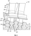
- each of the turbine blades 201 typically has an airfoil shape with opposed leading and trailing edges 202 and 203 and opposed pressure and suction surfaces 204 and 205 that extend radially outwardly from a root 206 to a tip.
- each of the turbine blades 201 is secured to a rotor assembly 210 by a fir tree structure 220.
- the fir tree structure 220 includes a blade part 221, which extends radially inwardly from the root 206 and which has an inward taper with outwardly extending lobes 222, and rotor assembly parts 223.
- the rotor assembly parts 223 are provided on either side of the blade part 221 and have outward tapers and recesses 224 that receive the outwardly extending lobes 222.
- centrifugal force acts on the fir tree structure 220 and causes radially outward facing surfaces of the outwardly extending lobes 222 to impinge upon radially inward facing surfaces of the recesses 224 to thereby secure the rotor blades 201 in place.
- a fir tree structure of a turbine blade is provided with varying spline profiles.
- This fir tree structure can be used with gas turbine engines, such as the gas turbine engine 20 of FIG. 1 , as well as other types of turbine engines, such as non-fan or turbo-shaft engines (i.e., where a gearbox is powered, transmitting power to helicopter rotors and secondly to a gearbox driving a propeller).
- the fir tree structure is enabled by machining processes, such as electro-discharge machining (EDM), milling, laser cutting, etc.
- EDM electro-discharge machining
- the varying spline profiles result in the fir tree structure being optimized for stress across varying operational ranges.
- a best-circular fixing process is optimized by replacing circular radii of the fir tree structure with splines that are adjusted to minimize peak stresses.
- the splines can be symmetrical on both sides of the fir tree structure or they can be different from one another (i.e., a profile under the pressure side rail can be different in shape from the profile under the suction side rail). While optimal shapes of the splines can be at least slightly different in each case to account for differences between exact stress patterns, which varies depending on lobe shapes, stiffness, broach angles, airfoil and pocket shapes, etc., spline radii will generally be reduced in areas of highest stress and increased where stresses are lower.
- a fir tree structure 301 of a turbine blade 302 is provided and includes a blade part 310 or a disc part.
- the blade part 310 is configured to extend radially inwardly from a root of the turbine blade 302 and that has an inward taper with decreasing radial position.
- the blade part 310 has a spline profile 320 forming blade fixing lobes 321 and blade fixing necks 322, which are interleaved with the blade fixing lobes 321.
- the spline profile 320 has constantly changing radii of curvature characterized in that the radii of curvature are relatively reduced in high stress locations and relatively increased in low stress locations.
- the blade fixing lobes 321 include an inboard blade fixing lobe 321 1 and an outboard blade fixing lobe 321 2 , which is wider than the inboard blade fixing lobe 321 1 .
- the blade fixing necks 322 include an inboard blade fixing neck 322 1 , which is inboard from the outboard blade fixing lobe 321 2 , and an outboard blade fixing neck 322 2 , which is outboard of the outboard blade fixing lobe 321 2 and wider than the inboard blade fixing neck 322 1 .
- the spline profile 320 further includes non-curvature (i.e., flat) portions at transitions 323 between the blade fixing lobes 321 and the blade fixing necks 322.
- a plot of curvature, or the inverse of the radii, along the outboard blade fixing neck 322 2 exhibits a first hump 501, a second hump 502 of significantly greater amplitude than the first hump 501 and a third hump 503 of slightly greater amplitude than the second hump 502.
- This plot can be taken from a starting point S at an outboard portion of the outboard blade fixing neck 322 2 to an ending point E at an inboard portion of the outboard blade fixing neck 322 2 .
- the second hump 502 is interposed between the first and third humps 501 and 503 and the first, second and third humps 501, 502 and 503 can have a similar pitch.
- a plot of curvature, or the inverse of the radii, along the inboard blade fixing neck 322 1 exhibits a hump 701 and a trough 702.
- This plot can be taken from a starting point S at an outboard portion of the inboard blade fixing neck 322 1 to an ending point E at an inboard portion of the inboard blade fixing neck 322 1 .
- FIGS. 4, 5 , 6, and 7 there can generally be a low amplitude plot of curvature in a neck of a fir tree structure in relative close proximity to blade and disc fir tree contact surfaces. This is due to bending and shear forces, which potentially increase fir tree neck stresses.
- a method of forming a fir tree structure of a turbine blade includes providing a blade part extending radially inwardly from the turbine blade and having an inward taper (801) and forming the blade part to have a spline profile forming blade fixing lobes and blade fixing necks, which are interleaved with the blade fixing lobes (802).
- the forming of the blade part of 602 includes identifying high and low stress locations of the blade part (6021) and designing the spline profile to have constantly changing radii of curvature characterized in that the radii of curvature are relatively reduced in the high stress locations and relatively increased in the low stress locations (8022).
- the forming of the blade part of 602 can include machining (8023) or another similar process.
Landscapes
- Engineering & Computer Science (AREA)
- Mechanical Engineering (AREA)
- General Engineering & Computer Science (AREA)
- Turbine Rotor Nozzle Sealing (AREA)
Abstract
A fir tree structure (301) is provided and includes a part (310) extending radially inwardly from a rotating part and having an inward taper. The part (310) has a spline profile (320) forming fixing lobes (321) and necks (322), which are interleaved with the fixing lobes (321). The spline profile (320) has constantly changing radii of curvature characterized in that the radii of curvature are relatively reduced in high stress locations and relatively increased in low stress locations.
Description
- The present disclosure relates turbines and, more particularly, to a dovetail structure of a turbine blade with splines forming a fixing profile.
- A turbine is used to generate power for propulsion, in some cases, by turning propellers, fans or helicopter blades through a gearbox. In some instances, the gearbox output is used to power electrical generators. In a gas turbine engine, fuel and compressed oxygen are combusted in a combustor to produce a high-temperature and high-pressure fluid. This fluid enters a turbine and interacts with rows or stages of turbine blades and vanes. This interaction causes the stages of turbine blades to rotate a rotor. The rotor rotation drives a compressor to compress the oxygen for the combustor and, as noted above, can be used to drive operations of a generator to produce electricity or for propulsion.
- According to an aspect of the disclosure, a fir tree structure is provided and includes a part extending radially inwardly from a rotating part and having an inward taper. The part has a spline profile forming fixing lobes and necks, which are interleaved with the fixing lobes. The spline profile has constantly changing radii of curvature characterized in that the radii of curvature are relatively reduced in high stress locations and relatively increased in low stress locations.
- In a further embodiment of the previous embodiment, the fixing lobes include an inboard fixing lobe and an outboard fixing lobe, which is wider than the inboard fixing lobe and the fixing necks include an inboard fixing neck, which is inboard from the outboard fixing lobe, and an outboard fixing neck, which is outboard of the outboard fixing lobe and wider than the inboard fixing neck.
- In a further embodiment of any of the previous embodiments, the spline profile includes non-curvature portions at transitions between the fixing lobes and the fixing necks.
- In a further embodiment of any of the previous embodiments, a plot of curvature along the outboard fixing neck exhibits a first hump, a second hump of significantly greater amplitude than the first hump and a third hump of slightly greater amplitude than the second hump.
- In a further embodiment of any of the previous embodiments, the plot of the curvature along the outboard fixing neck is taken from a starting point at an outboard portion of the outboard fixing neck to an ending point at an inboard portion of the outboard fixing neck.
- In a further embodiment of any of the previous embodiments, the second hump is interposed between the first and third humps.
- In a further embodiment of any of the previous embodiments, the first, second and third humps have a similar pitch.
- In a further embodiment of any of the previous embodiments, a plot of curvature along the inboard fixing neck exhibits a hump, a trough and an inflexion point between the hump and the trough that is closer to the hump.
- In a further embodiment of any of the previous embodiments, the plot of the curvature along the outboard fixing neck is taken from a starting point at an outboard portion of the inboard fixing neck to an ending point at an inboard portion of the inboard fixing neck
- According to an aspect of the disclosure, a fir tree structure of a turbine blade is provided and includes a blade part extending radially inwardly from the turbine blade and having an inward taper. The blade part has a spline profile forming blade fixing lobes and blade fixing necks, which are interleaved with the blade fixing lobes. The spline profile has constantly changing radii of curvature characterized in that the radii of curvature are relatively reduced in high stress locations and relatively increased in low stress locations.
- In a further embodiment of any of the previous embodiments, the blade fixing lobes include an inboard blade fixing lobe and an outboard blade fixing lobe, which is wider than the inboard blade fixing lobe and the blade fixing necks include an inboard blade fixing neck, which is inboard from the outboard blade fixing lobe, and an outboard blade fixing neck, which is outboard of the outboard blade fixing lobe and wider than the inboard blade fixing neck.
- In a further embodiment of any of the previous embodiments, the spline profile includes non-curvature portions at transitions between the blade fixing lobes and the blade fixing necks.
- In a further embodiment of any of the previous embodiments, a plot of curvature along the outboard blade fixing neck exhibits a first hump, a second hump of significantly greater amplitude than the first hump and a third hump of slightly greater amplitude than the second hump.
- In a further embodiment of any of the previous embodiments, the plot of the curvature along the outboard blade fixing neck is taken from a starting point at an outboard portion of the outboard blade fixing neck to an ending point at an inboard portion of the outboard blade fixing neck.
- In a further embodiment of any of the previous embodiments, the second hump is interposed between the first and third humps.
- In a further embodiment of any of the previous embodiments, the first, second and third humps have a similar pitch.
- In a further embodiment of any of the previous embodiments, a plot of curvature along the inboard blade fixing neck exhibits a hump, a trough and an inflexion point between the hump and the trough that is closer to the hump.
- In a further embodiment of any of the previous embodiments, the plot of the curvature along the outboard blade fixing neck is taken from a starting point at an outboard portion of the inboard blade fixing neck to an ending point at an inboard portion of the inboard blade fixing neck.
- According to an aspect of the disclosure, a method of forming a fir tree structure of a turbine blade is provided. The method includes providing a part extending radially inwardly from the turbine blade and having an inward taper and forming the part to have a spline profile forming fixing lobes and fixing necks, which are interleaved with the fixing lobes. The forming of the part includes identifying high and low stress locations of the part and designing the spline profile to have constantly changing radii of curvature characterized in that the radii of curvature are relatively reduced in the high stress locations and relatively increased in the low stress locations.
- In a further embodiment of any of the previous embodiments, the part includes a blade part.
- In a further embodiment of any of the previous embodiments, the forming of the part includes machining.
- Additional features and advantages are realized through the techniques of the present disclosure. Other embodiments and aspects of the disclosure are described in detail herein and are considered a part of the claimed technical concept. For a better understanding of the disclosure with the advantages and the features, refer to the description and to the drawings.
- For a more complete understanding of this disclosure, reference is now made to the following brief description, taken in connection with the accompanying drawings and detailed description, wherein like reference numerals represent like parts:
-
FIG. 1 is a partial cross-sectional view of a portion of an exemplary gas turbine engine in accordance with embodiments; -
FIG. 2 is a perspective view of a fir tree structure of a turbine blade in accordance with embodiments; -
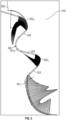
FIG. 3 is a graphical depiction of a spline profile of a fir tree structure in accordance with embodiments; -
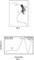
FIG. 4 is a graphical depiction of curvature (1/radii) of a portion of a spline profile of a fir tree structure in accordance with embodiments; -
FIG. 5 is a plot of the curvature (1/radii) ofFIG. 4 in accordance with embodiments; -
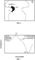
FIG. 6 is a graphical depiction of curvature (1/radii) of a portion of a spline profile of a fir tree structure in accordance with embodiments; -
FIG. 7 is a plot of the curvature (1/radii) ofFIG. 6 in accordance with embodiments; and -
FIG. 8 is a flow diagram illustrating a method of forming a fir tree structure in accordance with embodiments. -
FIG. 1 schematically illustrates agas turbine engine 20. Thegas turbine engine 20 is disclosed herein as a two-spool turbofan that generally incorporates afan section 22, acompressor section 24, acombustor section 26 and aturbine section 28. Alternative engines might include other systems or features. Thefan section 22 drives air along a bypass flow path B in a bypass duct, while thecompressor section 24 drives air along a core flow path C for compression and communication into thecombustor section 26 then expansion through theturbine section 28. Although depicted as a two-spool turbofan gas turbine engine in the disclosed non-limiting embodiment, it should be understood that the concepts described herein are not limited to use with two-spool turbofans as the teachings may be applied to other types of turbine engines including three-spool architectures. - The
exemplary engine 20 generally includes alow speed spool 30 and ahigh speed spool 32 mounted for rotation about an engine central longitudinal axis A relative to an enginestatic structure 36 viaseveral bearing systems 38. It should be understood thatvarious bearing systems 38 at various locations may alternatively or additionally be provided, and the location ofbearing systems 38 may be varied as appropriate to the application. - The
low speed spool 30 generally includes aninner shaft 40 that interconnects afan 42, alow pressure compressor 44 and alow pressure turbine 46. Theinner shaft 40 is connected to thefan 42 through a speed change mechanism, which in exemplarygas turbine engine 20 is illustrated as a gearedarchitecture 48 to drive thefan 42 at a lower speed than thelow speed spool 30. Thehigh speed spool 32 includes anouter shaft 50 that interconnects ahigh pressure compressor 52 andhigh pressure turbine 54. Acombustor 56 is arranged inexemplary gas turbine 20 between thehigh pressure compressor 52 and thehigh pressure turbine 54. An enginestatic structure 36 is arranged generally between thehigh pressure turbine 54 and thelow pressure turbine 46. The enginestatic structure 36 further supports bearingsystems 38 in theturbine section 28. Theinner shaft 40 and theouter shaft 50 are concentric and rotate viabearing systems 38 about the engine central longitudinal axis A which is collinear with their longitudinal axes. - The core airflow is compressed by the
low pressure compressor 44 then thehigh pressure compressor 52, mixed and burned with fuel in thecombustor 56, then expanded over thehigh pressure turbine 54 andlow pressure turbine 46. Theturbines low speed spool 30 andhigh speed spool 32 in response to the expansion. It will be appreciated that each of the positions of thefan section 22,compressor section 24,combustor section 26,turbine section 28, and fandrive gear system 48 may be varied. For example,gear system 48 may be located aft ofcombustor section 26 or even aft ofturbine section 28, andfan section 22 may be positioned forward or aft of the location ofgear system 48. - With continued reference to
FIG. 1 and with additional reference toFIG. 2 , multiple stages of rotating parts, such asturbine blades 201, are provided to interact with working fluid within theturbine section 28 ofFIG. 1 to in turn drive rotation of a rotor (i.e., the high-speed spool 30 ofFIG. 1 ). Each of theturbine blades 201 typically has an airfoil shape with opposed leading and trailingedges suction surfaces root 206 to a tip. At theroot 206, each of theturbine blades 201 is secured to arotor assembly 210 by afir tree structure 220. For eachturbine blade 201, thefir tree structure 220 includes ablade part 221, which extends radially inwardly from theroot 206 and which has an inward taper with outwardly extendinglobes 222, androtor assembly parts 223. Therotor assembly parts 223 are provided on either side of theblade part 221 and have outward tapers and recesses 224 that receive the outwardly extendinglobes 222. When theturbine blades 201 and the rotor rotate, centrifugal force acts on thefir tree structure 220 and causes radially outward facing surfaces of the outwardly extendinglobes 222 to impinge upon radially inward facing surfaces of therecesses 224 to thereby secure therotor blades 201 in place. - In conventional turbines, the curves of the outward projections and the recesses of a typical fir tree structure have simple geometries and uniform radii of curvatures over extended surface areas. In practice, such simple geometries and uniform curvatures were found to lead to non-optimal mechanical interactions and stress concentrations.
- Therefore, a need exists for fir tree structures of turbine blades that have improved mechanical interactions and reduced or eliminated stress concentrations.
- Thus, as will be discussed below, a fir tree structure of a turbine blade is provided with varying spline profiles. This fir tree structure can be used with gas turbine engines, such as the
gas turbine engine 20 ofFIG. 1 , as well as other types of turbine engines, such as non-fan or turbo-shaft engines (i.e., where a gearbox is powered, transmitting power to helicopter rotors and secondly to a gearbox driving a propeller). In any case, the fir tree structure is enabled by machining processes, such as electro-discharge machining (EDM), milling, laser cutting, etc. The varying spline profiles result in the fir tree structure being optimized for stress across varying operational ranges. During design phases, a best-circular fixing process is optimized by replacing circular radii of the fir tree structure with splines that are adjusted to minimize peak stresses. The splines can be symmetrical on both sides of the fir tree structure or they can be different from one another (i.e., a profile under the pressure side rail can be different in shape from the profile under the suction side rail). While optimal shapes of the splines can be at least slightly different in each case to account for differences between exact stress patterns, which varies depending on lobe shapes, stiffness, broach angles, airfoil and pocket shapes, etc., spline radii will generally be reduced in areas of highest stress and increased where stresses are lower. - With reference to
FIG. 3 ,FIGS. 4 and 5 andFIGS. 6 and 7 , a fir tree structure 301 of aturbine blade 302 is provided and includes ablade part 310 or a disc part. Theblade part 310 is configured to extend radially inwardly from a root of theturbine blade 302 and that has an inward taper with decreasing radial position. Theblade part 310 has aspline profile 320 forming blade fixing lobes 321 and blade fixing necks 322, which are interleaved with the blade fixing lobes 321. Thespline profile 320 has constantly changing radii of curvature characterized in that the radii of curvature are relatively reduced in high stress locations and relatively increased in low stress locations. The blade fixing lobes 321 include an inboard blade fixing lobe 3211 and an outboard blade fixing lobe 3212, which is wider than the inboard blade fixing lobe 3211. The blade fixing necks 322 include an inboard blade fixing neck 3221, which is inboard from the outboard blade fixing lobe 3212, and an outboard blade fixing neck 3222, which is outboard of the outboard blade fixing lobe 3212 and wider than the inboard blade fixing neck 3221. Thespline profile 320 further includes non-curvature (i.e., flat) portions attransitions 323 between the blade fixing lobes 321 and the blade fixing necks 322. - As shown in
FIGS. 4 and 5 , a plot of curvature, or the inverse of the radii, along the outboard blade fixing neck 3222 exhibits afirst hump 501, asecond hump 502 of significantly greater amplitude than thefirst hump 501 and athird hump 503 of slightly greater amplitude than thesecond hump 502. This plot can be taken from a starting point S at an outboard portion of the outboard blade fixing neck 3222 to an ending point E at an inboard portion of the outboard blade fixing neck 3222. In accordance with embodiments, thesecond hump 502 is interposed between the first andthird humps third humps - As, shown in
FIGS. 6 and 7 , a plot of curvature, or the inverse of the radii, along the inboard blade fixing neck 3221 exhibits ahump 701 and atrough 702. This plot can be taken from a starting point S at an outboard portion of the inboard blade fixing neck 3221 to an ending point E at an inboard portion of the inboard blade fixing neck 3221. In accordance with embodiments, there can be aninflexion point 703 between thehump 701 and thetrough 702 but closer to thehump 701. - As shown in
FIGS. 4, 5 ,6, and 7 , there can generally be a low amplitude plot of curvature in a neck of a fir tree structure in relative close proximity to blade and disc fir tree contact surfaces. This is due to bending and shear forces, which potentially increase fir tree neck stresses. - With references to
FIG. 8 , a method of forming a fir tree structure of a turbine blade is provided and includes providing a blade part extending radially inwardly from the turbine blade and having an inward taper (801) and forming the blade part to have a spline profile forming blade fixing lobes and blade fixing necks, which are interleaved with the blade fixing lobes (802). The forming of the blade part of 602 includes identifying high and low stress locations of the blade part (6021) and designing the spline profile to have constantly changing radii of curvature characterized in that the radii of curvature are relatively reduced in the high stress locations and relatively increased in the low stress locations (8022). The forming of the blade part of 602 can include machining (8023) or another similar process. - Technical effects and benefits of the present disclosure are the provision of a fir tree structure of a turbine blade that is provided with varying spline profiles. This is enabled by machining and other similar processes. The varying spline profiles result in the fir tree structure being optimized for stress across varying operational ranges.
- The corresponding structures, materials, acts, and equivalents of all means or step plus function elements in the claims below are intended to include any structure, material, or act for performing the function in combination with other claimed elements as specifically claimed. The description of the present disclosure has been presented for purposes of illustration and description, but is not intended to be exhaustive or limited to the technical concepts in the form disclosed. Many modifications and variations will be apparent to those of ordinary skill in the art without departing from the scope and spirit of the disclosure. The embodiments were chosen and described in order to best explain the principles of the disclosure and the practical application, and to enable others of ordinary skill in the art to understand the disclosure for various embodiments with various modifications as are suited to the particular use contemplated.
- While the preferred embodiments to the disclosure have been described, it will be understood that those skilled in the art, both now and in the future, may make various improvements and enhancements which fall within the scope of the claims which follow. These claims should be construed to maintain the proper protection for the disclosure first described.
Claims (12)
- A fir tree structure (301), comprising:a part (310) extending radially inwardly from a rotating part and having an inward taper,the part (310) having a spline profile (320) forming fixing lobes (321) and necks (322), which are interleaved with the fixing lobes (321),the spline profile (320) having constantly changing radii of curvature characterized in that the radii of curvature are relatively reduced in high stress locations and relatively increased in low stress locations.
- The fir tree structure (301) according to claim 1, wherein:the fixing lobes (321) comprise an inboard fixing lobe (3211) and an outboard fixing lobe (3212), which is wider than the inboard fixing lobe (3211), andthe fixing necks (322) comprise an inboard fixing neck (3221), which is inboard from the outboard fixing lobe (3212), and an outboard fixing neck (3222), which is outboard of the outboard fixing lobe (3212) and wider than the inboard fixing neck (3221).
- The fir tree structure (301) according to claim 2, wherein the spline profile (320) comprises non-curvature portions at transitions (323) between the fixing lobes (321) and the fixing necks (322).
- The fir tree structure (301) according to claim 2 or 3, wherein a plot of curvature along the outboard fixing neck (3222) exhibits a first hump (501), a second hump (502) of significantly greater amplitude than the first hump (501) and a third hump (503) of slightly greater amplitude than the second hump (502).
- The fir tree structure (301) according to claim 4, wherein the plot of the curvature along the outboard fixing neck (3222) is taken from a starting point (S) at an outboard portion of the outboard fixing neck (3222) to an ending point (E) at an inboard portion of the outboard fixing neck (3222).
- The fir tree structure (301) according to claim 4 or 5, wherein the second hump (502) is interposed between the first and third humps (501, 503).
- The fir tree structure (301) according to claim 4, 5 or 6, wherein the first, second and third humps (501, 502, 503) have a similar pitch.
- The fir tree structure (301) according to any of claims 2 to 7, wherein a plot of curvature along the inboard fixing neck (3221) exhibits a hump (701), a trough (702) and an inflexion point (703) between the hump (701) and the trough (702) that is closer to the hump (701).
- The fir tree structure (301) according to claim 8, wherein the plot of the curvature along the outboard fixing neck (3222) is taken from a starting point (S) at an outboard portion of the inboard fixing neck (3221) to an ending point (E) at an inboard portion of the inboard fixing neck (3221).
- The fir tree structure (301) of any preceding claim, wherein:
the part (310) is a blade part, the rotating part is a turbine blade (302), the fixing lobes (321) are blade fixing lobes and the fixing necks (322) are blade fixing necks. - A method of forming a fir tree structure (301) of a turbine blade (302), the method comprising:providing a part (310) extending radially inwardly from the turbine blade (302) and having an inward taper; andforming the part (310) to have a spline profile (320) forming fixing lobes (321) and fixing necks (322), which are interleaved with the fixing lobes (321),the forming of the part comprising:identifying high and low stress locations of the part (310); anddesigning the spline profile (320) to have constantly changing radii of curvature characterized in that the radii of curvature are relatively reduced in the high stress locations and relatively increased in the low stress locations.
- The method according to claim 11, wherein the part (310) comprises a blade part.
Applications Claiming Priority (1)
| Application Number | Priority Date | Filing Date | Title |
|---|---|---|---|
| US18/340,601 US12305533B2 (en) | 2023-06-23 | 2023-06-23 | Turbine rotor dovetail structure with splines |
Publications (1)
| Publication Number | Publication Date |
|---|---|
| EP4481163A1 true EP4481163A1 (en) | 2024-12-25 |
Family
ID=91664841
Family Applications (1)
| Application Number | Title | Priority Date | Filing Date |
|---|---|---|---|
| EP24183977.8A Pending EP4481163A1 (en) | 2023-06-23 | 2024-06-24 | Turbine rotor dovetail structure with splines |
Country Status (3)
| Country | Link |
|---|---|
| US (2) | US12305533B2 (en) |
| EP (1) | EP4481163A1 (en) |
| CA (1) | CA3237649A1 (en) |
Families Citing this family (1)
| Publication number | Priority date | Publication date | Assignee | Title |
|---|---|---|---|---|
| US12305533B2 (en) | 2023-06-23 | 2025-05-20 | Pratt & Whitney Canada Corp. | Turbine rotor dovetail structure with splines |
Citations (6)
| Publication number | Priority date | Publication date | Assignee | Title |
|---|---|---|---|---|
| US4191509A (en) * | 1977-12-27 | 1980-03-04 | United Technologies Corporation | Rotor blade attachment |
| JPH08100603A (en) * | 1994-10-01 | 1996-04-16 | Abb Manag Ag | Rotor with turbomachine blades |
| CA2306547A1 (en) * | 1999-04-30 | 2000-10-30 | General Electric Company | Stress relieved blade support |
| US20050175461A1 (en) * | 2004-02-10 | 2005-08-11 | General Electric Company | Advanced firtree and broach slot forms for turbine stage 3 buckets and rotor wheels |
| DE102008002942A1 (en) * | 2007-07-16 | 2009-01-22 | Nuovo Pignone Holding S.P.A. | Steam turbine and rotating blade |
| CN106194274A (en) * | 2015-05-12 | 2016-12-07 | 安萨尔多能源瑞士股份公司 | Turbine engine rotor including blade-shaft connection and blades for said rotor |
Family Cites Families (25)
| Publication number | Priority date | Publication date | Assignee | Title |
|---|---|---|---|---|
| GB2238581B (en) * | 1989-11-30 | 1994-01-12 | Rolls Royce Plc | Improved attachment of a gas turbine engine blade to a turbine rotor disc |
| US5147180A (en) * | 1991-03-21 | 1992-09-15 | Westinghouse Electric Corp. | Optimized blade root profile for steam turbine blades |
| US5160242A (en) | 1991-05-31 | 1992-11-03 | Westinghouse Electric Corp. | Freestanding mixed tuned steam turbine blade |
| US5176500A (en) | 1992-03-24 | 1993-01-05 | Westinghouse Electric Corp. | Two-lug side-entry turbine blade attachment |
| GB2345943B (en) | 1998-12-04 | 2003-07-09 | Glenn Bruce Sinclair | Precision crowning of blade attachments in gas turbines |
| DE19941134C1 (en) * | 1999-08-30 | 2000-12-28 | Mtu Muenchen Gmbh | Blade crown ring for gas turbine aircraft engine has each blade provided with transition region between blade surface and blade platform having successively decreasing curvature radii |
| JP4918806B2 (en) * | 2006-04-06 | 2012-04-18 | 株式会社日立製作所 | Turbine rotor and turbine blade |
| US20080050238A1 (en) | 2006-08-24 | 2008-02-28 | Pratt & Whitney Canada Corp. | Disc firtree slot with truncation for blade attachment |
| GB2442449B (en) * | 2006-10-04 | 2008-06-11 | Rolls Royce Plc | Forming firtree profiles |
| US8047796B2 (en) | 2007-11-16 | 2011-11-01 | General Electric Company | Dovetail attachment for use with turbine assemblies and methods of assembling turbine assemblies |
| EP2546465A1 (en) | 2011-07-14 | 2013-01-16 | Siemens Aktiengesellschaft | Blade root, corresponding blade, rotor disc, and turbomachine assembly |
| WO2014163680A1 (en) | 2013-03-10 | 2014-10-09 | Rivers Jonathan M | Attachment feature of a gas turbine engine blade having a curved profile |
| US9932834B2 (en) | 2013-03-13 | 2018-04-03 | United Technologies Corporation | Rotor blade with a conic spline fillet at an intersection between a platform and a neck |
| WO2016195689A1 (en) | 2015-06-04 | 2016-12-08 | Siemens Energy, Inc. | Attachment system for turbine engine airfoil |
| WO2017033226A1 (en) * | 2015-08-21 | 2017-03-02 | 三菱重工コンプレッサ株式会社 | Steam turbine |
| EP3575556A1 (en) | 2018-06-01 | 2019-12-04 | Siemens Aktiengesellschaft | Turbine blade assembly and method for manufacturing such blades |
| DE102019207620A1 (en) | 2019-05-24 | 2020-11-26 | MTU Aero Engines AG | Blade with blade root contour with a straight line section provided in a concave contour section |
| DE102019219403A1 (en) | 2019-12-12 | 2021-06-17 | MTU Aero Engines AG | Rotor for a turbo machine and turbo machine |
| US11578607B2 (en) | 2020-12-15 | 2023-02-14 | Pratt & Whitney Canada Corp. | Airfoil having a spline fillet |
| DE102021120876A1 (en) | 2021-08-11 | 2023-02-16 | MTU Aero Engines AG | BLADE BASE HOLDER TO ACCEPT A BLADE |
| KR102696226B1 (en) * | 2021-10-27 | 2024-08-16 | 두산에너빌리티 주식회사 | Turbine vane, turbine including the same |
| US12180857B2 (en) | 2023-04-21 | 2024-12-31 | Rtx Corporation | Turbine airfoil attachment with serration profile |
| US12305533B2 (en) | 2023-06-23 | 2025-05-20 | Pratt & Whitney Canada Corp. | Turbine rotor dovetail structure with splines |
| CN118391102A (en) | 2024-05-22 | 2024-07-26 | 东方电气集团东方汽轮机有限公司 | Blade root of moving blade of large turbine |
| CN119658601A (en) | 2024-11-20 | 2025-03-21 | 无锡透平叶片有限公司 | Split type longitudinal tree-shaped tenon tooth blade root diamond roller and design method thereof |
-
2023
- 2023-06-23 US US18/340,601 patent/US12305533B2/en active Active
-
2024
- 2024-05-07 CA CA3237649A patent/CA3237649A1/en active Pending
- 2024-06-24 EP EP24183977.8A patent/EP4481163A1/en active Pending
-
2025
- 2025-05-14 US US19/208,302 patent/US12650082B2/en active Active
Patent Citations (6)
| Publication number | Priority date | Publication date | Assignee | Title |
|---|---|---|---|---|
| US4191509A (en) * | 1977-12-27 | 1980-03-04 | United Technologies Corporation | Rotor blade attachment |
| JPH08100603A (en) * | 1994-10-01 | 1996-04-16 | Abb Manag Ag | Rotor with turbomachine blades |
| CA2306547A1 (en) * | 1999-04-30 | 2000-10-30 | General Electric Company | Stress relieved blade support |
| US20050175461A1 (en) * | 2004-02-10 | 2005-08-11 | General Electric Company | Advanced firtree and broach slot forms for turbine stage 3 buckets and rotor wheels |
| DE102008002942A1 (en) * | 2007-07-16 | 2009-01-22 | Nuovo Pignone Holding S.P.A. | Steam turbine and rotating blade |
| CN106194274A (en) * | 2015-05-12 | 2016-12-07 | 安萨尔多能源瑞士股份公司 | Turbine engine rotor including blade-shaft connection and blades for said rotor |
Also Published As
| Publication number | Publication date |
|---|---|
| US12650082B2 (en) | 2026-06-09 |
| US20240426221A1 (en) | 2024-12-26 |
| US12305533B2 (en) | 2025-05-20 |
| US20250270935A1 (en) | 2025-08-28 |
| CA3237649A1 (en) | 2025-10-30 |
Similar Documents
| Publication | Publication Date | Title |
|---|---|---|
| EP1835147B1 (en) | Fan assembly and corresponding gas turbine engine | |
| EP1890008B1 (en) | Rotor blade | |
| US7887299B2 (en) | Rotary body for turbo machinery with mistuned blades | |
| GB2482247A (en) | Metallic sheath | |
| US20090097979A1 (en) | Rotor blade | |
| EP2900929B1 (en) | Fan blade with tall dovetail for individually bladed rotors | |
| EP2809882B1 (en) | Compressor disk bleed air scallops | |
| CA2789467A1 (en) | Non axis-symmetric stator vane endwall contour | |
| WO2014028056A1 (en) | Contoured flowpath surface | |
| EP3686438B1 (en) | Fan blade | |
| EP3486496B1 (en) | Fan for gas turbine engines having mid-span shroud | |
| US20250270935A1 (en) | Turbine rotor dovetail structure with splines | |
| EP2971570B1 (en) | Fan blade dovetail and spacer | |
| US20060280610A1 (en) | Turbine blade and method of fabricating same | |
| US20200157953A1 (en) | Composite fan blade with abrasive tip | |
| WO2017222518A1 (en) | Ceramic matrix composite tip shroud assembly for gas turbines | |
| EP3399146B1 (en) | Method of manufacturing a vane arrangement for a gas turbine engine | |
| WO2013172903A2 (en) | Tapered thermal coating for airfoil | |
| US12188371B1 (en) | Turbine rotor dovetail structure with splines | |
| EP3550111B1 (en) | Turbine blade shroud for gas turbine engine with power turbine and method of manufacturing same | |
| US20200224542A1 (en) | Fir tree root for a bladed disc | |
| US20200355081A1 (en) | Shroud interlock | |
| US12435634B2 (en) | Notched turbine airfoils for weight reduction in gas turbine engines | |
| EP4553285A1 (en) | Turbine engine with a blade assembly having cooling holes | |
| US12509991B2 (en) | Turbine engine with a blade assembly having a set of cooling conduits |
Legal Events
| Date | Code | Title | Description |
|---|---|---|---|
| PUAI | Public reference made under article 153(3) epc to a published international application that has entered the european phase |
Free format text: ORIGINAL CODE: 0009012 |
|
| STAA | Information on the status of an ep patent application or granted ep patent |
Free format text: STATUS: THE APPLICATION HAS BEEN PUBLISHED |
|
| AK | Designated contracting states |
Kind code of ref document: A1 Designated state(s): AL AT BE BG CH CY CZ DE DK EE ES FI FR GB GR HR HU IE IS IT LI LT LU LV MC ME MK MT NL NO PL PT RO RS SE SI SK SM TR |
|
| STAA | Information on the status of an ep patent application or granted ep patent |
Free format text: STATUS: REQUEST FOR EXAMINATION WAS MADE |
|
| 17P | Request for examination filed |
Effective date: 20250625 |