EP4481153A1 - Screening arrangement with a top casing and a bottom element comprising a screening body receiving space - Google Patents
Screening arrangement with a top casing and a bottom element comprising a screening body receiving space Download PDFInfo
- Publication number
- EP4481153A1 EP4481153A1 EP23217801.2A EP23217801A EP4481153A1 EP 4481153 A1 EP4481153 A1 EP 4481153A1 EP 23217801 A EP23217801 A EP 23217801A EP 4481153 A1 EP4481153 A1 EP 4481153A1
- Authority
- EP
- European Patent Office
- Prior art keywords
- screening
- bottom element
- screening arrangement
- profile
- arrangement
- Prior art date
- Legal status (The legal status is an assumption and is not a legal conclusion. Google has not performed a legal analysis and makes no representation as to the accuracy of the status listed.)
- Pending
Links
Images






Classifications
-
- E—FIXED CONSTRUCTIONS
- E06—DOORS, WINDOWS, SHUTTERS, OR ROLLER BLINDS IN GENERAL; LADDERS
- E06B—FIXED OR MOVABLE CLOSURES FOR OPENINGS IN BUILDINGS, VEHICLES, FENCES OR LIKE ENCLOSURES IN GENERAL, e.g. DOORS, WINDOWS, BLINDS, GATES
- E06B9/00—Screening or protective devices for wall or similar openings, with or without operating or securing mechanisms; Closures of similar construction
- E06B9/24—Screens or other constructions affording protection against light, especially against sunshine; Similar screens for privacy or appearance; Slat blinds
- E06B9/26—Lamellar or like blinds, e.g. venetian blinds
- E06B9/38—Other details
- E06B9/388—Details of bottom or upper slats or their attachment
-
- E—FIXED CONSTRUCTIONS
- E04—BUILDING
- E04D—ROOF COVERINGS; SKY-LIGHTS; GUTTERS; ROOF-WORKING TOOLS
- E04D13/00—Special arrangements or devices in connection with roof coverings; Protection against birds; Roof drainage ; Sky-lights
- E04D13/03—Sky-lights; Domes; Ventilating sky-lights
- E04D13/033—Sky-lights; Domes; Ventilating sky-lights provided with means for controlling the light-transmission or the heat-reflection, (e.g. shields, reflectors, cleaning devices)
-
- E—FIXED CONSTRUCTIONS
- E06—DOORS, WINDOWS, SHUTTERS, OR ROLLER BLINDS IN GENERAL; LADDERS
- E06B—FIXED OR MOVABLE CLOSURES FOR OPENINGS IN BUILDINGS, VEHICLES, FENCES OR LIKE ENCLOSURES IN GENERAL, e.g. DOORS, WINDOWS, BLINDS, GATES
- E06B9/00—Screening or protective devices for wall or similar openings, with or without operating or securing mechanisms; Closures of similar construction
- E06B9/24—Screens or other constructions affording protection against light, especially against sunshine; Similar screens for privacy or appearance; Slat blinds
- E06B9/26—Lamellar or like blinds, e.g. venetian blinds
- E06B9/28—Lamellar or like blinds, e.g. venetian blinds with horizontal lamellae, e.g. non-liftable
- E06B9/30—Lamellar or like blinds, e.g. venetian blinds with horizontal lamellae, e.g. non-liftable liftable
- E06B9/32—Operating, guiding, or securing devices therefor
- E06B9/322—Details of operating devices, e.g. pulleys, brakes, spring drums, drives
-
- E—FIXED CONSTRUCTIONS
- E06—DOORS, WINDOWS, SHUTTERS, OR ROLLER BLINDS IN GENERAL; LADDERS
- E06B—FIXED OR MOVABLE CLOSURES FOR OPENINGS IN BUILDINGS, VEHICLES, FENCES OR LIKE ENCLOSURES IN GENERAL, e.g. DOORS, WINDOWS, BLINDS, GATES
- E06B9/00—Screening or protective devices for wall or similar openings, with or without operating or securing mechanisms; Closures of similar construction
- E06B9/24—Screens or other constructions affording protection against light, especially against sunshine; Similar screens for privacy or appearance; Slat blinds
- E06B9/40—Roller blinds
- E06B9/42—Parts or details of roller blinds, e.g. suspension devices, blind boxes
-
- E—FIXED CONSTRUCTIONS
- E06—DOORS, WINDOWS, SHUTTERS, OR ROLLER BLINDS IN GENERAL; LADDERS
- E06B—FIXED OR MOVABLE CLOSURES FOR OPENINGS IN BUILDINGS, VEHICLES, FENCES OR LIKE ENCLOSURES IN GENERAL, e.g. DOORS, WINDOWS, BLINDS, GATES
- E06B9/00—Screening or protective devices for wall or similar openings, with or without operating or securing mechanisms; Closures of similar construction
- E06B9/56—Operating, guiding or securing devices or arrangements for roll-type closures; Spring drums; Tape drums; Counterweighting arrangements therefor
- E06B9/64—Operating, guiding or securing devices or arrangements for roll-type closures; Spring drums; Tape drums; Counterweighting arrangements therefor with lowerable roller
-
- E—FIXED CONSTRUCTIONS
- E06—DOORS, WINDOWS, SHUTTERS, OR ROLLER BLINDS IN GENERAL; LADDERS
- E06B—FIXED OR MOVABLE CLOSURES FOR OPENINGS IN BUILDINGS, VEHICLES, FENCES OR LIKE ENCLOSURES IN GENERAL, e.g. DOORS, WINDOWS, BLINDS, GATES
- E06B9/00—Screening or protective devices for wall or similar openings, with or without operating or securing mechanisms; Closures of similar construction
- E06B9/56—Operating, guiding or securing devices or arrangements for roll-type closures; Spring drums; Tape drums; Counterweighting arrangements therefor
- E06B9/68—Operating devices or mechanisms, e.g. with electric drive
- E06B9/70—Operating devices or mechanisms, e.g. with electric drive comprising an electric motor positioned outside the roller
-
- E—FIXED CONSTRUCTIONS
- E06—DOORS, WINDOWS, SHUTTERS, OR ROLLER BLINDS IN GENERAL; LADDERS
- E06B—FIXED OR MOVABLE CLOSURES FOR OPENINGS IN BUILDINGS, VEHICLES, FENCES OR LIKE ENCLOSURES IN GENERAL, e.g. DOORS, WINDOWS, BLINDS, GATES
- E06B9/00—Screening or protective devices for wall or similar openings, with or without operating or securing mechanisms; Closures of similar construction
- E06B9/56—Operating, guiding or securing devices or arrangements for roll-type closures; Spring drums; Tape drums; Counterweighting arrangements therefor
- E06B9/92—Means allowing the closures to be shifted out of the plane of the opening
-
- E—FIXED CONSTRUCTIONS
- E06—DOORS, WINDOWS, SHUTTERS, OR ROLLER BLINDS IN GENERAL; LADDERS
- E06B—FIXED OR MOVABLE CLOSURES FOR OPENINGS IN BUILDINGS, VEHICLES, FENCES OR LIKE ENCLOSURES IN GENERAL, e.g. DOORS, WINDOWS, BLINDS, GATES
- E06B9/00—Screening or protective devices for wall or similar openings, with or without operating or securing mechanisms; Closures of similar construction
- E06B9/24—Screens or other constructions affording protection against light, especially against sunshine; Similar screens for privacy or appearance; Slat blinds
- E06B2009/2476—Solar cells
-
- E—FIXED CONSTRUCTIONS
- E06—DOORS, WINDOWS, SHUTTERS, OR ROLLER BLINDS IN GENERAL; LADDERS
- E06B—FIXED OR MOVABLE CLOSURES FOR OPENINGS IN BUILDINGS, VEHICLES, FENCES OR LIKE ENCLOSURES IN GENERAL, e.g. DOORS, WINDOWS, BLINDS, GATES
- E06B9/00—Screening or protective devices for wall or similar openings, with or without operating or securing mechanisms; Closures of similar construction
- E06B9/24—Screens or other constructions affording protection against light, especially against sunshine; Similar screens for privacy or appearance; Slat blinds
- E06B9/26—Lamellar or like blinds, e.g. venetian blinds
- E06B9/262—Lamellar or like blinds, e.g. venetian blinds with flexibly-interconnected horizontal or vertical strips; Concertina blinds, i.e. upwardly folding flexible screens
- E06B2009/2625—Pleated screens, e.g. concertina- or accordion-like
-
- E—FIXED CONSTRUCTIONS
- E06—DOORS, WINDOWS, SHUTTERS, OR ROLLER BLINDS IN GENERAL; LADDERS
- E06B—FIXED OR MOVABLE CLOSURES FOR OPENINGS IN BUILDINGS, VEHICLES, FENCES OR LIKE ENCLOSURES IN GENERAL, e.g. DOORS, WINDOWS, BLINDS, GATES
- E06B9/00—Screening or protective devices for wall or similar openings, with or without operating or securing mechanisms; Closures of similar construction
- E06B9/24—Screens or other constructions affording protection against light, especially against sunshine; Similar screens for privacy or appearance; Slat blinds
- E06B9/26—Lamellar or like blinds, e.g. venetian blinds
- E06B9/28—Lamellar or like blinds, e.g. venetian blinds with horizontal lamellae, e.g. non-liftable
- E06B9/30—Lamellar or like blinds, e.g. venetian blinds with horizontal lamellae, e.g. non-liftable liftable
- E06B9/32—Operating, guiding, or securing devices therefor
- E06B9/322—Details of operating devices, e.g. pulleys, brakes, spring drums, drives
- E06B2009/3222—Cordless, i.e. user interface without cords
Definitions
- the present invention relates to a screening arrangement for a window, preferably a roof window, said window comprising a frame with a top member, a bottom member and two mutually parallel side members, said screening arrangement comprising a screening body having two side edges and a top and bottom portion and configured to assume rolled-up, folded-up or collapsed condition in a non-screening position, a top casing accommodating at least the top portion of the screening body, said top casing comprising a front rail, a top cover portion, and a back cover portion, the front rail defining a first direction corresponding to a width direction of the screening arrangement, the first direction being perpendicular to a second direction corresponding to a longitudinal direction, the first and second direction being perpendicular to a third direction corresponding to a depth direction, a bottom element connected to the bottom portion of the screening body and being configured to be longitudinally positionable in said longitudinal direction by means of electric drive means, between the non-screening position of the screening body and a screening position, in which the screening body has been
- Screening arrangements of this kind are known in the art and from commercially available products such as VELUX ® DSL and RSL. Electrically operated screening arrangements powered by solar panels facing the exterior in the mounted condition have numerous advantages compared to screening arrangement powered by the mains power of the building in which the window to be screened is installed, including easy retrofitting and sustainably sourced energy. Examples of prior art screening arrangements with solar panels on the exterior side of the bottom element include KR 101811684 B1 , US 2019/0277086 A1 , and WO 02/41740 A1 .
- a screening arrangement of the kind mentioned in the introduction which is furthermore characterised in that the top edge of the back portion of the bottom element is located at a higher level than the upwards facing surface, that the bottom element comprises a receiving space for receiving a part of the rolled-up, folded-up or collapsed screening body in the non-screening position, said receiving space being delimited in the longitudinal direction by a first plane substantially parallel with a plane spanned by the width direction and the depth direction, and a second plane parallel with the first plane and located at a higher level than the first plane, that the first plane is defined by a lowest point on the upwards facing surface, and the second plane is defined by a top edge of the front or a top edge of the back portion of the bottom element, whichever is located at the highest level as seen in the longitudinal direction, and that at least the top portion of the screening body is located to the exterior of and above a bottom edge of the front rail of the top casing such that a majority of the rolled-up, folded-up or collapse
- the bottom element contributes to the available space for storing the screening body in the non-screening position, thus contributing to the compactness of the screening arrangement.
- the screening body is thus accommodated in a combined space comprising the volume dedicated to the screening body within the top casing and the receiving space within the bottom element.
- the configuration of the inventive screening arrangement contributes to solving the inherent conflict between the need for the screening body to cover the entire window opening in the fully screening position on the one hand, while it on the other hand is desirable that as much as possible of the screening body is hidden from view and the entire screening arrangement takes up as little place as possible in the longitudinal direction in the non-screening position. Since the top edge of the back portion of the bottom element is located at a higher level than the upwards facing surface, it is at all times ensured that a sufficient area for the solar panels or panels is available on the back side of the bottom element.
- the top casing and the volume dedicated to accommodating the screening body within the top casing accordingly in order to ensure an optimum fit between the bottom element and the top casing in the non-screening position.
- the top edge of the front of the bottom element is located at a higher level than the top edge of the back portion.
- a U-shaped configuration is formed at the upper section of the bottom element in which the front of the bottom element is rendered the tallest component of the bottom element which in turn has the advantage that the front may contribute to protecting and hiding from view the lower part of the rolled-up, folded-up or collapsed screening body as seen from the interior of the building in the non-screening position.
- a further advantage is that there is more flexibility in forming the back portion of the bottom element and the back cover portion of the top casing. This configuration provides the possibility of optimising the combined space available for accommodating the screening body in that the contribution from the bottom element by its receiving space may be made quite substantial and even larger than the contribution from the dedicated volume within the top casing.
- the top edge of the front of the bottom element is located at a lower level than the top edge of the back portion.
- the top edge of the front of the bottom element is located at substantially the same level as the upwards facing surface, that is, an L-shaped configuration of the upper section is achieved, by which the height of the solar panel(s) may be optimised without special requirements to the front of the bottom element.
- the top edge of the front of the bottom element is located at substantially the same level as the bottom edge of the front rail of the top casing in the non-screening position. This provides for a good protection of the screening body from dust and other airborne impurities in the interior of the building that could otherwise settle on the screening body, in addition to the visually pleasing appearance of the screening arrangement in the non-screening position.
- the top edge of the back portion of the bottom element is located at substantially the same level as a bottom edge of the back cover portion of the top casing in the non-screening position. In this way, a barrier towards the exterior is formed such that the screening body is protected from incident light, thus mitigating the detrimental effects of UV exposure on the material of the screening body.
- the bottom element may be manufactured in any suitable manner.
- the bottom element comprises a main portion composed by a set of profiles defining a cross-sectional shape of the bottom element, and two end portions located at respective longitudinal ends of the main portion of the bottom element.
- profiles which may for instance be formed by extrusion, makes it possible to standardise the production to a considerable extent and facilitates assembly of the screening arrangement.
- one and the same profile may be used for forming the front of the bottom element, while different profiles may be used on the exterior side of the front to take varying configurations depending on the type of screening device including type of screening body. In turn, this makes it possible to obtain a harmonised appearance towards the interior for an entire product line of screening arrangements.
- a first profile comprises the front of the bottom element and a second profile comprises the back portion and the upwards facing surface of the bottom element, a third profile being preferably provided for fastening the bottom portion of the screening body.
- This configuration is particularly well-suited for screening devices comprising a roller blind which typically require fastening of the bottom portion of the screening body is connected close to the top edge of the front.
- a first profile comprises the front of the bottom element and a second profile comprises the back portion
- a third profile comprises the upwards facing surface of the bottom element and is provided with means for fastening the bottom portion of the screening body.
- a particular advantage in forming the bottom element by a set of profiles is achieved in an embodiment in which the first profile has a length exceeding the length of the second profile such that a space is provided at each longitudinal end of the main portion to accommodate parts of the end portions to the exterior of the front comprised in the first profile, as seen in the depth direction. In this way, the exterior end portions are hidden from view and protected from the interior of the building.
- each at least one solar panel has a height substantially corresponding to the height of the exterior side of the back portion of the bottom element.
- the usage of the available area is optimised.
- the requirements to the power supply from the solar panel(s) depends to some extent on the size of the screening device of the screening arrangement, that is, the dimensioning of the available capacity is dependent on the size of roof window in which the screening arrangement is to be installed.
- screening arrangements intended for small-sized roof windows may be provided with a single solar panel, while larger versions will require two or more solar panels.
- one presently preferred embodiment provides for the exterior side of the back portion of the bottom element being configured to receive two or more solar panels, optionally one or more blind panels is/are provided to be replaced by one or more additional solar panel(s).
- the bottom element comprises an operating space to accommodate operating means of the electric drive means. While such operating means may to some extent be provided in other components, it is preferred to include such means in the bottom element while still allowing appropriate room for the receiving space within the bottom element.
- the operating space is located below said receiving space, separated by the upwards facing surface of the bottom element. This provides for a satisfactory compactness and also effectively divides the operating space including the operating means from the screening body accommodated within the receiving space.
- the screening arrangement further comprises two side rails configured to be connected to the top casing, preferably to the front rail of the top casing, and to be connected to the side members of the frame so as to extend in the longitudinal direction in the mounted condition of the screening arrangement.
- Such side rails are useful in many ways; they may provide guidance of the side edges of the screening body and optionally of the bottom element during movement of the screening body in the window opening, transmission means of the operating means of the electric drive means may be positioned in the side rails, and finally, the side rails provide an easy way of preventing the screening body from hanging in the inclined mounted condition of most roof windows, just as a pleasant, picture-frame like appearance is achieved.
- the top casing is composed by a set of profiles defining a cross-sectional shape of the top casing, and wherein two end pieces are connected to respective longitudinal ends of the top casing.
- configuring the top casing may take place in accordance with the type of screening device and improves the flexibility in designing the interaction between the bottom element and the top casing, in particular in the non-screening position.
- a first profile comprises the front rail, the top cover portion and the back cover portion, and a second profile comprises an additional back element.
- a first profile comprises the front rail, the top cover portion and the back cover portion
- a second profile comprises fastening means for the top portion of the screening body.
- a feature described in relation to one of the aspects may also be incorporated in the other aspect, and the advantage of the feature is applicable to all aspects in which it is incorporated.
- FIGS. 1 to 3 an embodiment of a screening arrangement generally designated 10 is shown, mounted in a frame 2 representing a window.
- the frame 2 constitutes a pane-carrying sash of a roof window 1 and may be pivotable about a centre axis, or top-hung, relative to a stationary frame (not shown) of the roof window 1.
- the frame 2 may likewise be a stationary frame, which in a mounted position of the window lines an aperture in a building.
- the term "frame” is to be understood as incorporating any substantially rectangular structure positioned in any opening in a building, whether in a wall or the roof, and surrounding an opening 3 to be screened.
- the screening arrangement 10 may thus be utilised in connection with e.g.
- the screening arrangement 10 will be described as an interior screening arrangement mounted on the interior side of a roof window, i.e., the side facing an inside room of a building, in other words an internal, or an interior, roof window screening arrangement 10.
- the frame 2 has a top member 2.1, two mutually parallel side members 2.2, 2.3, and a bottom member 2.4, surrounding the opening 3 to be screened, covered by a suitable panel element such as insulating glazing in the form of a pane 4.
- a suitable panel element such as insulating glazing in the form of a pane 4.
- the screening arrangement 10 comprises a screening device including a screening body 15 having two side edges and a top and bottom portion, to be shown and described below.
- the screening body 15 is typically made from cloth or fabric, which may be flexible to allow rolling up, but may also be pleated, as will be described below in connection with the individual embodiments.
- other screening devices having other kinds of screening bodies are conceivable for use in the screening arrangement of the invention.
- the term "screening body” is intended to encompass all feasible types of screening bodies, examples being roller blinds, lamella blinds, curtains, awnings, roller shutters, and shades.
- the screening device of the screening arrangement 10 further comprises a top casing 11 located at the top member 2.1 of the frame in the mounted condition of the screening arrangement 10.
- a top portion of the screening body 15 is typically fastened to a winding, folding, or rotating structure such as a spring-biased roller bar accommodated in the top casing 11, which also accommodates the top portion of the screening body 15.
- a bottom element 14 of the screening device of the screening arrangement 10 is connected to a bottom portion of the screening body 15 and configured to be longitudinally positionable in the longitudinal direction L between a non-screening position of the screening body 15 as shown in FIG. 1 and one of a number of screening positions in which the screening body 15 has been deployed, including a fully screening position in which the bottom element 14 is positioned at or near the bottom member 2.4 of the frame 2.
- the screening body 15 In the non-screening position of the screening body 15, the screening body 15 is configured to assume a rolled-up, folded-up or collapsed condition, at least partly accommodated within the top casing 11 as will be described in further detail below.
- each side rail 12 comprises a first flange 121, a second flange 122 and a leg 123.
- the leg 123 extends at substantially right angles to the first and second flanges 121, 122 and serves to fasten the side rail 12 to the frame 2.
- an upper end of the side rails 12, 13 is connected to a respective longitudinal end of the top casing 11.
- the movement of the bottom element 14 and hence of the screening body 15 is provided by means of electric drive means operably connecting the bottom element 14 and the side rails 12, 13 as will be described in some detail below.
- the screening arrangement comprises a position indicator 16 slidably positionable along one or the other of the side rails 12, 13 for manually indicating a desired longitudinal position of the bottom element 14.
- the position indicator 16 will be described as being positioned on the right-hand side rail 12.
- the longitudinal position of said position indicator 16 is manually adjustable by physical movement of the position indicator to an arbitrary longitudinal position along the side rail 12.
- the bottom element 14 is provided with a notch 141 by which the position indicator 16 is able to be brought into releasable positive engagement. Further details of such a position indicator are given in Applicant's co-pending EP applications.
- FIGS. 4 to 7 an embodiment is shown in which the screening device of the screening arrangement 10 is a roller blind.
- the screening arrangement 10 is shown in a front and rear view, respectively, and in a screening position.
- the screening body 15 defines a screening plane in the screening position substantially parallel to a plane defined by the longitudinal direction L and the width direction W. Side edges 152, 153, or elements at the side edges, of the screening body 15 and end portions of the bottom element 14 are guided in respective side rails 12, 13.
- top portion 151 and a bottom portion 154 of the screening body 15 are indicated in FIG. 4 . It is noted that the terms top portion and bottom portion of the screening body 15 denote the position the respective portions assume in a mounted condition of the screening arrangement 10. Other mounting positions are conceivable.
- the screening device is electrically operated by means of electric drive means 22 of the screening arrangement 10.
- energy is required.
- the energy may be collected from solar panels 27 as shown in FIGS. 5 and 6 , possibly also by mains power supply, and optionally supplemented by battery means 28 (shown in Fig. 17 ).
- solar panels 27 For the solar panels to be able to be exposed to as much sunlight as possible it is preferred to have the solar panels 27 placed on the side of the bottom element 14 facing the window glazing, assuming the screening arrangement 10 is mounted on the inside side of a window.
- the solar panel generally extends in a plane parallel to the screening plane.
- FIGS. 6 and 7 include operating means of the electric drive means 22.
- the operating means comprise a cogwheel 144 for interacting with a rack 124 on each side rail 12, 13 to translate rotational movement of the cogwheel 144 to translational movement of the bottom element 14.
- One cogwheel 144 is present at each longitudinal end portion of the bottom element 14, as shown on a rotatable shaft 143, and the cogwheels 144 constitute first transmission means to interact with second transmission means including the two racks 124 arranged in the respective side rails 12, 13 to facilitate the translational movement of the bottom element 14 along the longitudinal direction L.
- Other drive means are conceivable.
- Further elements of the operating means of the electric drive means accommodated in the bottom element 14 may include battery means and a printed circuit board.
- each longitudinal end portion etc. is to be understood throughout the description and claims that the cogwheels are provided at, near, or proximate such end portions of the bottom element. This does not exclude that parts, portions or components of the bottom element may be present beyond the position of the cogwheel, as seen the longitudinal direction of the bottom element, or width direction W of the screening arrangement 10.
- near or proximate it is meant that the cogwheels are disposed or oriented so as to engage a corresponding rack to move the screening body between a screening position or state and a non-screening position or state when such operation is desired, i.e., moving between a screening position or state and a non-screening position or state.
- Typical ranges for any distance between the cogwheels and the respective physical end portion of the bottom element are 0 to 20 mm, in particular 5 to 10 mm.
- the rack is located in conjunction with, associated with, or on the side rail in question.
- the rack may be formed as a separate part connected to the side rail, be formed integrally with, or constitute a portion of the side rail.
- end pieces of the top casing 11 interact with suitable mounting brackets (not shown) provided for instance on the side members 2.2, 2.3 of the frame 2.
- suitable mounting brackets are well-known in the art and are typically pre-mounted in commercially available roof windows, comprising a standard version or a version including electric contacts as described in Applicant's European patents Nos. 2002079 and 3203008 .
- An exemplary prior art standard mounting bracket is shown in Applicant's co-pending EP application filed on the same day as the present application.
- FIG. 8 provides a detailed rear view of the top casing 11 as shown in FIG. 5 , in which an end piece 25 is shown to interact with a standard version mounting bracket. This is made possible, since the solar panels 27, possibly supplemented by battery means, provide the power required to operate the screening arrangement 10.
- FIG. 9 shows a detailed side view of the top casing 11 of an alternative embodiment in which the end piece 25 is provided with electric terminals 25a for interaction with a mounting bracket including electric contacts, for instance of the kind mentioned in the above.
- the top casing 11 has a general configuration well-known from for instance Applicant's WO 2008/131757 A1 and WO 2008/131761 A1 .
- the top casing 11 comprises a front rail 114 provided as a rail-like element with a surface facing the interior in the mounted condition of the screening arrangement 10.
- the front rail 114 defines a first direction corresponding to the width direction W of the screening arrangement 10, the first direction being perpendicular to a second direction corresponding to the longitudinal direction L, the first and second direction being perpendicular to a third direction corresponding to the depth direction D.
- the front rail 114 has a predefined height, i.e. extension in the length direction L, between a top edge 114a and a bottom edge 114b.
- the surface corresponds in substance to the surface of the side rails 12, 13 and the side rails 12, 13 typically have a dimension in the width direction W in the mounted condition of the screening arrangement 10 corresponding to the height of the front rail 114.
- the front rail 114 is provided with two mitred ends to cooperate with counterpart mitred ends of the respective side rails 12, 13 to render the screening arrangement 10 with a picture frame-like appearance.
- the top casing 11 comprises a top cover portion 113 and a back cover portion 115 with a bottom edge 115b.
- the top casing 11 and, if present, the side rails 13, 14 are typically made from extruded profiles of an appropriate material such as aluminium or other material including composites.
- the top casing 11 is in the embodiment shown composed by a set of profiles 11a, 11b defining a cross-sectional shape of the top casing 11.
- the bottom element 14 comprises a front 140 and a back portion 149.
- An upwards facing surface 145 is present between the front 140 and the back portion 149.
- the back portion 149 has a top edge 149a and a generally plane extension in the longitudinal direction L.
- the back portion 149 accommodates the solar panel 27 (cf. FIGS. 5 and 6 ) on an exterior side, as seen in the mounted condition of the screening arrangement 10.
- the term "accommodate the solar panel” is intended to encompass that the solar panel or solar panels are connected to or received within parts or portions of the bottom element or fastened to the exterior side of the back portion by for instance adhesion.
- the screening device of the embodiment shown comprises a roller blind
- the screening body 15 is rolled-up on a rotatable roller assembly represented by a roller shaft 23.
- the roller assembly may comprise additional roller bars.
- the top portion 151 of the screening body 154 is fastened to the roller shaft 23 in a suitable manner.
- the bottom portion 154 of the screening body 15 is connected to the bottom element 14 at or near a top edge 140a of the front 140 of the bottom element 14.
- the bottom portion 154 is in the embodiment shown folded around a locking wire 154a; the package thus obtained is accommodated in a track in the bottom element 14.
- Other manners of connection are conceivable, as is well-known in the art.
- a receiving space RS for receiving at least a part of the rolled-up screening body 15 in the non-screening position is defined within the bottom element 14.
- the receiving space RS is delimited in the longitudinal direction L by a first plane P1 substantially parallel with a plane spanned by the width direction W and the depth direction D, and a second plane P2 parallel with the first plane P1 and located at a higher level than the first plane P1.
- the first plane P1 is generally defined by a lowest point on the upwards facing surface 145
- the second plane P2 is defined by either the top edge 140a of the front 140 or the top edge 149a of the back portion 149 of the bottom element 14, whichever is located at the highest level as seen in the longitudinal direction L. In the embodiment shown in FIG. 10 , the highest level is present at the top edge 140a of the front 140.
- the upwards facing surface 145 may as shown comprise a plane central portion but could in principle take any form. As such, the upwards facing surface 145 defines a lower-most point for contributing to the receiving space RS for accommodating the screening body 15.
- the upwards facing surface 145 also serves as a reference point, namely in that the top edge 149a of the back portion 149 is located at a higher level than the upwards facing surface 145. In this way, it is possible to provide the solar panel 27 with a maximised height in the longitudinal direction L, while at the same time, the bottom element 14 contributes to the available space for accommodating the screening body 15 in the non-screening position.
- the bottom element 14 is in a position corresponding to the non-screening position of the screening arrangement 10, as the top edge 140a of the front 140 of the bottom element 14 abuts or is close to the bottom edge 114b of the front rail 114 of the top casing 11.
- the top portion 151 of the screening body 15 is located to the exterior of the front rail 114, as seen in the depth direction D, and above the bottom edge 114b of the front rail 114, as seen in the longitudinal direction L. In this way, a majority of the rolled-up screening body 15 is accommodated in the combined space of the receiving space RS defined within the bottom element 14 and the top casing 11.
- the entire screening body 15 is accommodated in the combined space, about half within the top casing 11 and half within the receiving space RS in the bottom element 14.
- top casing 11 and the bottom element 144 also appears from FIG. 11 , in which the bottom element 14 has been moved downwards in the longitudinal direction L to deploy the screening body 15 such that a screening position of the screening arrangement 10 is achieved.
- FIGS. 10 and 11 Further details visible in FIGS. 10 and 11 include the configuration of the top casing 11 by the set of profiles 11a, 11b. While the profiles 11a, 11b define the cross-sectional shape of the top casing 11, two end pieces, for instance in the configuration mentioned in the above for the end piece 25 of FIG. 8 or FIG. 9 , are connected to respective longitudinal ends of the top casing 11 such that the top casing 11 forms a closed cavity or cassette in which the screening body 15 is at least partly accommodated in the non-screening position.
- the first profile 11a comprises the front rail 114 as well as the top cover portion 113 and the back cover portion 115.
- the second profile 11b forms an additional back element adjoining the back cover portion 115 such that there is no access to the roller shaft 23 or rolled-up screening body 15 in the non-screening position. It is noted that the second profile 11b extends below the level of the top edge 149a of the back portion 149 of the bottom element 14. In fact, the lower edge of the second profile 11b is located at the same level as the first plane P1 at the upwards facing surface 145 of the bottom element 14.
- the profiles 11a, 11b may be extruded and interconnected in any suitable manner.
- the bottom element 14 comprises a main portion composed by a set of profiles 14a, 14b, 14c defining a cross-sectional shape of the bottom element 14, and two end portions located at respective longitudinal ends of the main portion of the bottom element 14. Examples of two such end portions are visible in FIG. 6 and FIG. 7 , respectively, but will not be described in detail in the present application but are described in more detail in Applicant's co-pending patent application filed on the same date as the present application.
- the first profile 14a has a length exceeding the length of the second profile 14b such that a space is provided at each longitudinal end of the main portion to accommodate parts of the end portions to the exterior of the front 140 comprised in the first profile 14a, as seen in the depth direction D.
- the first profile 14a comprises the front 140 of the bottom element 14 and the second profile 14b comprises the back portion 149 and the upwards facing surface 145 of the bottom element 14, while the third profile 14c is provided for fastening the bottom portion 154 of the screening body 15.
- the third profile 14c is curved, forming a hollow to accommodate the rolled-up screening body 15 in the non-screening position.
- the profiles 14a, 14b, 14c may be extruded and interconnected in any suitable manner.
- the bottom element 14 comprises an operating space OS to accommodate operating means of the electric drive means 22, for instance including a motor, drive shafts etc.
- the operating space OS is here located below the receiving space RS and is separated from the receiving space RS by the upwards facing surface 145 of the bottom element 14.
- FIG. 12 another embodiment is shown, in which the top edge 140a of the front 140 of the bottom element 14 is located at a lower level than the top edge 149a of the back portion 149.
- the back portion 149 is able to accommodate one or more larger solar panels 27 as compared with the embodiment of FIGS. 10 and 11 .
- each such solar panel 27 may have a height substantially corresponding to the height of the exterior side of the back portion 149 of the bottom element 14.
- the top edge 149a of the back portion 149 of the bottom element 14 is in this embodiment located at substantially the same level as a bottom edge 115b of the back cover portion 115 of the top casing 11 in the non-screening position.
- FIG. 13 presents an upwards facing portion which is substantially L-shaped.
- the top edge 140a of the front 140 of the bottom element 14 is located at substantially the same level as the upwards facing surface 145.
- FIG. 13 A further detail of the embodiment of FIG. 13 is that the front 140 of the bottom element 14 has substantially the same configuration as the front rail 114 of the top casing 11. In this way, it is possible to provide the front rail 114 of the top casing 11, the front 140 of the bottom element 14, and the side rails 12, 13, if present, with substantially the same surface and dimensions, thus rendering a harmonised appearance of the screening arrangement 10 facing the interior, i.e. typically a room in a building.
- the back portion 149 still has a substantial extension in the height direction to allow for a satisfactory size of the solar panel or panels.
- the receiving space RS formed by the bottom element 14 may be increased by forming the profile constituting the front 140, the upwards facing surface 145 and the back portion 149 differently, for instance by shifting the upwards facing surface 145 downwards, such that the entire screening body 15 is able to be accommodated within the combined space provided by the top casing 11 and the receiving space RS within the bottom element 14 as is the case in the embodiment of FIGS. 10 and 11 .
- FIGS. 14 to 17 an alternative embodiment of a screening arrangement 10 according to the invention is shown. Reference is made also to the description of the above embodiment of FIGS. 4 to 7 , and only differences relative to that embodiment will be described in detail. Elements having the same or analogous function are denoted by the same reference numerals to which ⁇ has been added.
- the screening arrangement 10 in this embodiment comprises a screening device in the form of a pleated blind.
- a screening body 15' comprises a plurality of pleats which in the non-screening position shown in FIG. 14 are folded-up, or collapsed, into a stack of a certain height in the longitudinal direction L. It is noted that the term “folded-up” will be used throughout the description; however, the term is intended to encompass other types of screening bodies which open and close in an accordion-like fashion.
- the height of the stack depends on factors such as thickness of the material of the screening body 15' and the height of the screening device itself; that is, a taller roof window will require a larger number of pleats in the screening body 15' for a given material thickness.
- the screening body 15' is in fact visible from the interior in the non-screening position as indicated in FIG. 14 , different from the screening arrangement 10 of FIG. 4 .
- this is not necessarily the case in all variants of the alternative embodiments.
- FIG. 17 A further difference appears from FIG. 17 , namely that the exterior side of the back portion 149 of the bottom element 14 receives two solar panels 27. Although not shown in detail, further solar panels could be provided. Optionally, the bottom element 14 could accommodate one or more blind panels to be replaced by one or more additional solar panel(s). This configuration is conceivable also to the above embodiments.
- FIG. 18 it is seen how the first profile 14a of the bottom element 14 comprises the front 140 of the bottom element 14 as in the embodiment of FIGS. 4 to 7 and as illustrated in FIG. 10 .
- a second profile 14b' comprises the back portion 149
- a third profile 14c' comprises the upwards facing surface 145 of the bottom element 14.
- the third profile 14c' is provided with a stepped portion comprising the upwards facing surface 145 and provided with means for fastening the bottom portion 154' of the screening body 15'.
- the first profile 11a of the top casing 11 is configured basically as in the above embodiment and comprises the front rail 114, the top cover portion 113 and the back cover portion 115, whereas a second profile 11b comprises fastening means for the top portion 151' of the screening body 15'.
- the combined space for accommodating the folded-up screening body 15' formed by the top casing 11 and the receiving space RS of the bottom element 14 is in this embodiment of a smaller extent than in the above embodiment as illustrated by a comparison with FIG. 10 such that only just more than half of the stack of folded-up pleats is accommodated in the combined space.
- FIG. 19 a first variant of the alternative embodiment is shown.
- the folded-up screening body 15' is accommodated in its entirety in the combined space of the top casing 11 and the receiving space RS within the bottom element 14. This is made possible by the provision of a thinner cloth of the screening body 15' and/or a smaller height of the screening body 15'.
- manufacture of such pleated blinds takes into account dimensioning the screening body 15' to the largest size of screening arrangement 10 of a size range, as seen in the longitudinal direction L.
- screening arrangements for smaller roof windows thus have over-dimensioned screening bodies, that is, the screening body is normally too long and may thus be shortened without detriment to the functionality.
- FIG. 20 a second variant of the alternative embodiment is shown.
- the folded-up screening body 15' is accommodated in its entirety in the combined space of the top casing 11 and the receiving space RS within the bottom element 14 in this variant too.
- This is made possible by a different configuration of the second profile 14b' and the third profile 14c' such that the upwards facing surface 145 is retracted downwards in the longitudinal direction L as compared with the embodiment of FIG. 18 .
Landscapes
- Engineering & Computer Science (AREA)
- Structural Engineering (AREA)
- Architecture (AREA)
- Civil Engineering (AREA)
- Blinds (AREA)
Abstract
Screening arrangement with a top casing and a bottom element comprising a screening body receiving space.
In the screening arrangement (10), the screening body (15) is rolled-up, folded-up or collapsed in a non-screening position in a combined space of a top casing (11) and a receiving space (RS) in the bottom element (14). The top casing (11) comprises a front rail (114), a top cover portion (113), and a back cover portion (115). The bottom element (14) is connected to the bottom portion (154) of the screening body (15) and comprises a front (140), an upwards facing surface (145), and a back portion (149). The back portion (149) is configured to accommodate one or more solar panels (27) on an exterior side, facing the exterior in a mounted condition of the screening arrangement (10). The top edge (149a) of the back portion (149) of the bottom element (14) is located at a higher level than the upwards facing surface (145), and the receiving space (RS) is delimited in the longitudinal direction (L) by a first plane (P1) substantially parallel with a plane spanned by the width direction (W) and the depth direction (D), and a second plane (P2) parallel with the first plane (P1) and located at a higher level than the first plane (P1). The first plane (P1) is defined by a lowest point on the upwards facing surface (145), and the second plane (P2) is defined by a top edge (140a) of the front (140) or a top edge (149a) of the back portion (149) of the bottom element (14), whichever is located at the highest level as seen in the longitudinal direction (L), and at least the top portion (151) of the screening body is located to the exterior of and above a bottom edge (114b) of the front rail (114) of the top casing (11) such that a majority of the rolled-up, folded-up or collapsed screening body (15) is accommodated in said receiving space (RS) and the top casing (11) in the non-screening position.
Description
- The present invention relates to a screening arrangement for a window, preferably a roof window, said window comprising a frame with a top member, a bottom member and two mutually parallel side members, said screening arrangement comprising a screening body having two side edges and a top and bottom portion and configured to assume rolled-up, folded-up or collapsed condition in a non-screening position, a top casing accommodating at least the top portion of the screening body, said top casing comprising a front rail, a top cover portion, and a back cover portion, the front rail defining a first direction corresponding to a width direction of the screening arrangement, the first direction being perpendicular to a second direction corresponding to a longitudinal direction, the first and second direction being perpendicular to a third direction corresponding to a depth direction, a bottom element connected to the bottom portion of the screening body and being configured to be longitudinally positionable in said longitudinal direction by means of electric drive means, between the non-screening position of the screening body and a screening position, in which the screening body has been deployed, the bottom element comprising a front, an upwards facing surface, and a back portion, the back portion being configured to accommodate one or more solar panels on an exterior side, facing the exterior in a mounted condition of the screening arrangement.
- Screening arrangements of this kind are known in the art and from commercially available products such as VELUX® DSL and RSL. Electrically operated screening arrangements powered by solar panels facing the exterior in the mounted condition have numerous advantages compared to screening arrangement powered by the mains power of the building in which the window to be screened is installed, including easy retrofitting and sustainably sourced energy. Examples of prior art screening arrangements with solar panels on the exterior side of the bottom element include
KR 101811684 B1 US 2019/0277086 A1 , andWO 02/41740 A1 - In general, it is a desire that such solar panels take up as little space as possible, in particular in the non-screening position, so as to not impede the view. When screening windows installed in a façade of a building, there is generally more freedom in designing the components of the screening device including such solar panels, but in interior screening arrangements designated for use in roof windows, the location of the screening arrangement close to the windowpane, and in an inclined position, poses particular challenges due to the limited available space. Needless to say, the desire to minimise the size of the solar panels is in conflict with the need for collecting sufficient energy to power the screening device of the screening arrangement, possibly also by accumulating the collected energy in suitable storages such as batteries.
- With this background, it is therefore an object of the invention to provide a screening arrangement which is compact and which at the same time provides adequate room for the solar panel or panels.
- This and further objects are met by a screening arrangement of the kind mentioned in the introduction, which is furthermore characterised in that the top edge of the back portion of the bottom element is located at a higher level than the upwards facing surface, that the bottom element comprises a receiving space for receiving a part of the rolled-up, folded-up or collapsed screening body in the non-screening position, said receiving space being delimited in the longitudinal direction by a first plane substantially parallel with a plane spanned by the width direction and the depth direction, and a second plane parallel with the first plane and located at a higher level than the first plane, that the first plane is defined by a lowest point on the upwards facing surface, and the second plane is defined by a top edge of the front or a top edge of the back portion of the bottom element, whichever is located at the highest level as seen in the longitudinal direction, and that at least the top portion of the screening body is located to the exterior of and above a bottom edge of the front rail of the top casing such that a majority of the rolled-up, folded-up or collapsed screening body is accommodated in said receiving space and the top casing in the non-screening position.
- In this way, the bottom element contributes to the available space for storing the screening body in the non-screening position, thus contributing to the compactness of the screening arrangement. The screening body is thus accommodated in a combined space comprising the volume dedicated to the screening body within the top casing and the receiving space within the bottom element. The configuration of the inventive screening arrangement contributes to solving the inherent conflict between the need for the screening body to cover the entire window opening in the fully screening position on the one hand, while it on the other hand is desirable that as much as possible of the screening body is hidden from view and the entire screening arrangement takes up as little place as possible in the longitudinal direction in the non-screening position. Since the top edge of the back portion of the bottom element is located at a higher level than the upwards facing surface, it is at all times ensured that a sufficient area for the solar panels or panels is available on the back side of the bottom element.
- By providing the upper section of the bottom element with an L- or U-shaped configuration, it is possible to configure the top casing and the volume dedicated to accommodating the screening body within the top casing accordingly in order to ensure an optimum fit between the bottom element and the top casing in the non-screening position.
- In one presently preferred embodiment, the top edge of the front of the bottom element is located at a higher level than the top edge of the back portion. In this way, a U-shaped configuration is formed at the upper section of the bottom element in which the front of the bottom element is rendered the tallest component of the bottom element which in turn has the advantage that the front may contribute to protecting and hiding from view the lower part of the rolled-up, folded-up or collapsed screening body as seen from the interior of the building in the non-screening position. A further advantage is that there is more flexibility in forming the back portion of the bottom element and the back cover portion of the top casing. This configuration provides the possibility of optimising the combined space available for accommodating the screening body in that the contribution from the bottom element by its receiving space may be made quite substantial and even larger than the contribution from the dedicated volume within the top casing.
- In another embodiment, the top edge of the front of the bottom element is located at a lower level than the top edge of the back portion. This provides the possibility of providing the upper section of the bottom element as either a U-shaped or an L-shaped configuration, by which it is possible to form the back portion as the tallest component and hence maximise the available height in the longitudinal direction for the solar panel or panels.
- In a further development of this embodiment, the top edge of the front of the bottom element is located at substantially the same level as the upwards facing surface, that is, an L-shaped configuration of the upper section is achieved, by which the height of the solar panel(s) may be optimised without special requirements to the front of the bottom element.
- In one presently preferred embodiment, the top edge of the front of the bottom element is located at substantially the same level as the bottom edge of the front rail of the top casing in the non-screening position. This provides for a good protection of the screening body from dust and other airborne impurities in the interior of the building that could otherwise settle on the screening body, in addition to the visually pleasing appearance of the screening arrangement in the non-screening position.
- In another presently preferred embodiment, the top edge of the back portion of the bottom element is located at substantially the same level as a bottom edge of the back cover portion of the top casing in the non-screening position. In this way, a barrier towards the exterior is formed such that the screening body is protected from incident light, thus mitigating the detrimental effects of UV exposure on the material of the screening body.
- In principle, the bottom element may be manufactured in any suitable manner. In one presently preferred embodiment, the bottom element comprises a main portion composed by a set of profiles defining a cross-sectional shape of the bottom element, and two end portions located at respective longitudinal ends of the main portion of the bottom element. The use of profiles, which may for instance be formed by extrusion, makes it possible to standardise the production to a considerable extent and facilitates assembly of the screening arrangement. For instance, one and the same profile may be used for forming the front of the bottom element, while different profiles may be used on the exterior side of the front to take varying configurations depending on the type of screening device including type of screening body. In turn, this makes it possible to obtain a harmonised appearance towards the interior for an entire product line of screening arrangements.
- In one development of this preferred embodiment, a first profile comprises the front of the bottom element and a second profile comprises the back portion and the upwards facing surface of the bottom element, a third profile being preferably provided for fastening the bottom portion of the screening body. This configuration is particularly well-suited for screening devices comprising a roller blind which typically require fastening of the bottom portion of the screening body is connected close to the top edge of the front.
- In another development of this preferred embodiment, a first profile comprises the front of the bottom element and a second profile comprises the back portion, and a third profile comprises the upwards facing surface of the bottom element and is provided with means for fastening the bottom portion of the screening body. This configuration is particularly advantageous in screening devices having a screening body which is folded or collapsed in the non-screening position and in which the bottom portion of the screening body is typically fastened centrally in the bottom element as seen in the depth direction. This applies for instance to pleated blinds and cellular blinds. Regardless of the type of screening body, a particular advantage in forming the bottom element by a set of profiles is achieved in an embodiment in which the first profile has a length exceeding the length of the second profile such that a space is provided at each longitudinal end of the main portion to accommodate parts of the end portions to the exterior of the front comprised in the first profile, as seen in the depth direction. In this way, the exterior end portions are hidden from view and protected from the interior of the building.
- The configuration of the solar panel or panels is in principle arbitrary and the solar panel(s) may have any suitable dimensions, i.e. height in the longitudinal direction, length in the width direction, and thickness in the depth direction, but in one embodiment, each at least one solar panel has a height substantially corresponding to the height of the exterior side of the back portion of the bottom element. Thus, the usage of the available area is optimised.
- The requirements to the power supply from the solar panel(s) depends to some extent on the size of the screening device of the screening arrangement, that is, the dimensioning of the available capacity is dependent on the size of roof window in which the screening arrangement is to be installed. Hence, screening arrangements intended for small-sized roof windows may be provided with a single solar panel, while larger versions will require two or more solar panels. In order to improve the modularity of the components for a given size range during manufacture, one presently preferred embodiment provides for the exterior side of the back portion of the bottom element being configured to receive two or more solar panels, optionally one or more blind panels is/are provided to be replaced by one or more additional solar panel(s).
- In a further embodiment, the bottom element comprises an operating space to accommodate operating means of the electric drive means. While such operating means may to some extent be provided in other components, it is preferred to include such means in the bottom element while still allowing appropriate room for the receiving space within the bottom element.
- In one advantageous further development of this embodiment, the operating space is located below said receiving space, separated by the upwards facing surface of the bottom element. This provides for a satisfactory compactness and also effectively divides the operating space including the operating means from the screening body accommodated within the receiving space.
- In a presently preferred embodiment, the screening arrangement further comprises two side rails configured to be connected to the top casing, preferably to the front rail of the top casing, and to be connected to the side members of the frame so as to extend in the longitudinal direction in the mounted condition of the screening arrangement. Such side rails are useful in many ways; they may provide guidance of the side edges of the screening body and optionally of the bottom element during movement of the screening body in the window opening, transmission means of the operating means of the electric drive means may be positioned in the side rails, and finally, the side rails provide an easy way of preventing the screening body from hanging in the inclined mounted condition of most roof windows, just as a pleasant, picture-frame like appearance is achieved.
- In one presently preferred embodiment, the top casing is composed by a set of profiles defining a cross-sectional shape of the top casing, and wherein two end pieces are connected to respective longitudinal ends of the top casing. As for embodiments in which the bottom element is composed by a set of profiles, configuring the top casing may take place in accordance with the type of screening device and improves the flexibility in designing the interaction between the bottom element and the top casing, in particular in the non-screening position.
- In one further development of this preferred embodiment, a first profile comprises the front rail, the top cover portion and the back cover portion, and a second profile comprises an additional back element. This configuration is particularly advantageous in case the screening device of the screening arrangement is a roller blind.
- In another further development, a first profile comprises the front rail, the top cover portion and the back cover portion, and a second profile comprises fastening means for the top portion of the screening body. This provides for a particularly advantageous configuration in case the screening device is a pleated blind, or other types of blinds in which the screening body is folded-up or collapsed in the non-screening position.
- Other presently preferred embodiments and further advantages will be apparent from the subsequent detailed description and drawings.
- A feature described in relation to one of the aspects may also be incorporated in the other aspect, and the advantage of the feature is applicable to all aspects in which it is incorporated.
- In the following description embodiments of the invention will be described with reference to the drawings, in which
-
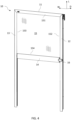
FIG. 1 is a plan view of a screening arrangement in an embodiment of the invention, mounted in a frame of a window; -
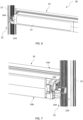
FIG. 2 is a partial view, on a larger scale, of the upper right-hand corner of the screening arrangement and window ofFIG. 1 ; -
FIG. 3 is a partial perspective view of a position indicator mounted on a side rail of the screening arrangement in the embodiment ofFIGS. 1 and 2 ; -
FIG. 4 is a perspective view of a screening arrangement in an embodiment of the invention, with the screening body in a screening position; -
FIG. 5 is a perspective view of the screening arrangement ofFIG. 4 , seen from a back side; -
FIG. 6 is a partial perspective view, on a larger scale, of a bottom element and a side rail of the screening arrangement ofFIG. 5 ; -
FIG. 7 is a partial perspective view, on a larger scale of the bottom element and the other side rail of the screening arrangement ofFIG. 5 ; -
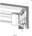
FIG. 8 is a partial perspective view of a screening arrangement including an end piece in an embodiment of the invention; -
FIG. 9 is a partial side view of a top casing, bottom element, and a side rail of a screening arrangement in an embodiment of the invention; -
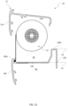
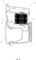
FIG. 10 is a cross-sectional view of a top casing and a bottom element of a screening arrangement in an embodiment of the invention; -
FIG. 11 is a view of the screening arrangement ofFIG. 10 , in a screening position; -
FIG. 12 is a view corresponding toFIG. 10 , of another embodiment of the screening arrangement of the invention; -
FIG. 13 is a view corresponding toFIG. 10 , of a further embodiment of the screening arrangement of the invention; -
FIG. 14 is a perspective view of a screening arrangement in an alternative embodiment of the invention; -
FIG. 15 is a perspective view of the screening arrangement ofFIG. 14 , seen from a back side; -
FIG. 16 is a partial perspective view, on a larger scale, of a bottom element and a side rail of the screening arrangement ofFIG. 15 ; -
FIG. 17 is a partial perspective view, on a larger scale of the bottom element and the other side rail of the screening arrangement ofFIG. 15 ; -
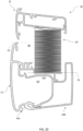
FIG. 18 is a cross-sectional view of a top casing and a bottom element of a screening arrangement in an embodiment of the invention, substantially corresponding to the embodiment ofFIGS. 14 to 17 ; -
FIG. 19 is a view corresponding toFIG. 18 , with a screening body having a different height than in the embodiment ofFIG. 18 ; and -
FIG. 20 is a view corresponding toFIG. 18 , of an alternative configuration of the bottom element than in the embodiment ofFIG. 18 . - In the following detailed description, preferred embodiments of the present invention will be described. However, it is to be understood that features of the different embodiments are exchangeable between the embodiments and may be combined in different ways, unless anything else is specifically indicated. It may also be noted that, for the sake of clarity, the dimensions of certain components illustrated in the drawings may differ from the corresponding dimensions in real-life implementations.
- It is noted that terms such as "up", "down", "left-hand", "right-hand", "exterior", "interior", "outer", "inner" are relative and refers to the viewpoint in question.
- Referring initially to
FIGS. 1 to 3 , an embodiment of a screening arrangement generally designated 10 is shown, mounted in aframe 2 representing a window. In the shown configuration, theframe 2 constitutes a pane-carrying sash of aroof window 1 and may be pivotable about a centre axis, or top-hung, relative to a stationary frame (not shown) of theroof window 1. Theframe 2 may likewise be a stationary frame, which in a mounted position of the window lines an aperture in a building. It is noted that the term "frame" is to be understood as incorporating any substantially rectangular structure positioned in any opening in a building, whether in a wall or the roof, and surrounding anopening 3 to be screened. Thescreening arrangement 10 may thus be utilised in connection with e.g. windows having a frame only, windows having a sash and a frame, or in doors. In the present context, thescreening arrangement 10 will be described as an interior screening arrangement mounted on the interior side of a roof window, i.e., the side facing an inside room of a building, in other words an internal, or an interior, roofwindow screening arrangement 10. - The
frame 2 has a top member 2.1, two mutually parallel side members 2.2, 2.3, and a bottom member 2.4, surrounding theopening 3 to be screened, covered by a suitable panel element such as insulating glazing in the form of apane 4. - The
screening arrangement 10 comprises a screening device including ascreening body 15 having two side edges and a top and bottom portion, to be shown and described below. Thescreening body 15 is typically made from cloth or fabric, which may be flexible to allow rolling up, but may also be pleated, as will be described below in connection with the individual embodiments. However, other screening devices having other kinds of screening bodies are conceivable for use in the screening arrangement of the invention. Hence, it is noted that as used herein the term "screening body" is intended to encompass all feasible types of screening bodies, examples being roller blinds, lamella blinds, curtains, awnings, roller shutters, and shades. - The screening device of the
screening arrangement 10 further comprises atop casing 11 located at the top member 2.1 of the frame in the mounted condition of thescreening arrangement 10. A top portion of thescreening body 15 is typically fastened to a winding, folding, or rotating structure such as a spring-biased roller bar accommodated in thetop casing 11, which also accommodates the top portion of thescreening body 15. - A
bottom element 14 of the screening device of thescreening arrangement 10 is connected to a bottom portion of thescreening body 15 and configured to be longitudinally positionable in the longitudinal direction L between a non-screening position of thescreening body 15 as shown inFIG. 1 and one of a number of screening positions in which thescreening body 15 has been deployed, including a fully screening position in which thebottom element 14 is positioned at or near the bottom member 2.4 of theframe 2. - In the non-screening position of the
screening body 15, thescreening body 15 is configured to assume a rolled-up, folded-up or collapsed condition, at least partly accommodated within thetop casing 11 as will be described in further detail below. - In the embodiment shown, two
side rails FIG. 3 . Referring also to figures of other embodiments described below, eachside rail 12 comprises afirst flange 121, asecond flange 122 and aleg 123. Theleg 123 extends at substantially right angles to the first andsecond flanges side rail 12 to theframe 2. In the embodiment shown, an upper end of the side rails 12, 13 is connected to a respective longitudinal end of thetop casing 11. - In the embodiments of the invention, the movement of the
bottom element 14 and hence of thescreening body 15 is provided by means of electric drive means operably connecting thebottom element 14 and the side rails 12, 13 as will be described in some detail below. - Finally, the screening arrangement comprises a
position indicator 16 slidably positionable along one or the other of the side rails 12, 13 for manually indicating a desired longitudinal position of thebottom element 14. In the following, theposition indicator 16 will be described as being positioned on the right-hand side rail 12. The longitudinal position of saidposition indicator 16 is manually adjustable by physical movement of the position indicator to an arbitrary longitudinal position along theside rail 12. Thebottom element 14 is provided with anotch 141 by which theposition indicator 16 is able to be brought into releasable positive engagement. Further details of such a position indicator are given in Applicant's co-pending EP applications. - Referring now also to
FIGS. 4 to 7 , an embodiment is shown in which the screening device of thescreening arrangement 10 is a roller blind. Thescreening arrangement 10 is shown in a front and rear view, respectively, and in a screening position. - The
screening body 15 defines a screening plane in the screening position substantially parallel to a plane defined by the longitudinal direction L and the width direction W. Side edges 152, 153, or elements at the side edges, of thescreening body 15 and end portions of thebottom element 14 are guided in respective side rails 12, 13. - The general positions of a
top portion 151 and abottom portion 154 of thescreening body 15 are indicated inFIG. 4 . It is noted that the terms top portion and bottom portion of thescreening body 15 denote the position the respective portions assume in a mounted condition of thescreening arrangement 10. Other mounting positions are conceivable. - In the embodiments shown, the screening device is electrically operated by means of electric drive means 22 of the
screening arrangement 10. In order for the electric drive means to work, energy is required. The energy may be collected fromsolar panels 27 as shown inFIGS. 5 and6 , possibly also by mains power supply, and optionally supplemented by battery means 28 (shown inFig. 17 ). For the solar panels to be able to be exposed to as much sunlight as possible it is preferred to have thesolar panels 27 placed on the side of thebottom element 14 facing the window glazing, assuming thescreening arrangement 10 is mounted on the inside side of a window. The solar panel generally extends in a plane parallel to the screening plane. - Further details shown in
FIGS. 6 and 7 include operating means of the electric drive means 22. The operating means comprise acogwheel 144 for interacting with arack 124 on eachside rail cogwheel 144 to translational movement of thebottom element 14. Onecogwheel 144 is present at each longitudinal end portion of thebottom element 14, as shown on arotatable shaft 143, and thecogwheels 144 constitute first transmission means to interact with second transmission means including the tworacks 124 arranged in the respective side rails 12, 13 to facilitate the translational movement of thebottom element 14 along the longitudinal direction L. Other drive means are conceivable. Further elements of the operating means of the electric drive means accommodated in thebottom element 14 may include battery means and a printed circuit board. - By the term "at each longitudinal end portion" etc. is to be understood throughout the description and claims that the cogwheels are provided at, near, or proximate such end portions of the bottom element. This does not exclude that parts, portions or components of the bottom element may be present beyond the position of the cogwheel, as seen the longitudinal direction of the bottom element, or width direction W of the
screening arrangement 10. By near or proximate, it is meant that the cogwheels are disposed or oriented so as to engage a corresponding rack to move the screening body between a screening position or state and a non-screening position or state when such operation is desired, i.e., moving between a screening position or state and a non-screening position or state. Typical ranges for any distance between the cogwheels and the respective physical end portion of the bottom element are 0 to 20 mm, in particular 5 to 10 mm. - By the term "in the side rail" etc. is to be understood that the rack is located in conjunction with, associated with, or on the side rail in question. The rack may be formed as a separate part connected to the side rail, be formed integrally with, or constitute a portion of the side rail.
- Depending on whether the screening arrangement is powered solely by
solar panels 27, possibly supplemented by battery means 28 as shown in the embodiment ofFig. 17 , or also by mains power, end pieces of thetop casing 11 interact with suitable mounting brackets (not shown) provided for instance on the side members 2.2, 2.3 of theframe 2. Such mounting brackets are well-known in the art and are typically pre-mounted in commercially available roof windows, comprising a standard version or a version including electric contacts as described in Applicant'sEuropean patents Nos. 2002079 and3203008 . An exemplary prior art standard mounting bracket is shown in Applicant's co-pending EP application filed on the same day as the present application. - In that regard, the embodiment shown in
FIG. 8 provides a detailed rear view of thetop casing 11 as shown inFIG. 5 , in which anend piece 25 is shown to interact with a standard version mounting bracket. This is made possible, since thesolar panels 27, possibly supplemented by battery means, provide the power required to operate thescreening arrangement 10. -
FIG. 9 shows a detailed side view of thetop casing 11 of an alternative embodiment in which theend piece 25 is provided withelectric terminals 25a for interaction with a mounting bracket including electric contacts, for instance of the kind mentioned in the above. - Regarding the configuration of the
top casing 11 and its interaction with thebottom element 14, particular reference is made toFIG. 10 . - The
top casing 11 has a general configuration well-known from for instance Applicant'sWO 2008/131757 A1 andWO 2008/131761 A1 . Thus, thetop casing 11 comprises afront rail 114 provided as a rail-like element with a surface facing the interior in the mounted condition of thescreening arrangement 10. Thefront rail 114 defines a first direction corresponding to the width direction W of thescreening arrangement 10, the first direction being perpendicular to a second direction corresponding to the longitudinal direction L, the first and second direction being perpendicular to a third direction corresponding to the depth direction D. Thefront rail 114 has a predefined height, i.e. extension in the length direction L, between atop edge 114a and abottom edge 114b. - In the embodiment shown, in which the
screening arrangement 10 is provided withside rails screening arrangement 10 corresponding to the height of thefront rail 114. Thefront rail 114 is provided with two mitred ends to cooperate with counterpart mitred ends of the respective side rails 12, 13 to render thescreening arrangement 10 with a picture frame-like appearance. - Furthermore, the
top casing 11 comprises atop cover portion 113 and aback cover portion 115 with abottom edge 115b. Thetop casing 11 and, if present, the side rails 13, 14 are typically made from extruded profiles of an appropriate material such as aluminium or other material including composites. As will be described in more detail below, thetop casing 11 is in the embodiment shown composed by a set ofprofiles top casing 11. - The
bottom element 14 comprises a front 140 and aback portion 149. An upwards facingsurface 145 is present between the front 140 and theback portion 149. Theback portion 149 has atop edge 149a and a generally plane extension in the longitudinal direction L. Theback portion 149 accommodates the solar panel 27 (cf.FIGS. 5 and6 ) on an exterior side, as seen in the mounted condition of thescreening arrangement 10. - The term "accommodate the solar panel" is intended to encompass that the solar panel or solar panels are connected to or received within parts or portions of the bottom element or fastened to the exterior side of the back portion by for instance adhesion.
- Since the screening device of the embodiment shown comprises a roller blind, the
screening body 15 is rolled-up on a rotatable roller assembly represented by aroller shaft 23. The roller assembly may comprise additional roller bars. Thetop portion 151 of thescreening body 154 is fastened to theroller shaft 23 in a suitable manner. In the embodiment shown, thebottom portion 154 of thescreening body 15 is connected to thebottom element 14 at or near atop edge 140a of thefront 140 of thebottom element 14. In order to provide connection of thescreening body 15 and thebottom element 14, thebottom portion 154 is in the embodiment shown folded around a locking wire 154a; the package thus obtained is accommodated in a track in thebottom element 14. Other manners of connection are conceivable, as is well-known in the art. - A receiving space RS for receiving at least a part of the rolled-up
screening body 15 in the non-screening position is defined within thebottom element 14. The receiving space RS is delimited in the longitudinal direction L by a first plane P1 substantially parallel with a plane spanned by the width direction W and the depth direction D, and a second plane P2 parallel with the first plane P1 and located at a higher level than the first plane P1. - The first plane P1 is generally defined by a lowest point on the
upwards facing surface 145, and the second plane P2 is defined by either thetop edge 140a of the front 140 or thetop edge 149a of theback portion 149 of thebottom element 14, whichever is located at the highest level as seen in the longitudinal direction L. In the embodiment shown inFIG. 10 , the highest level is present at thetop edge 140a of the front 140. - The
upwards facing surface 145 may as shown comprise a plane central portion but could in principle take any form. As such, theupwards facing surface 145 defines a lower-most point for contributing to the receiving space RS for accommodating thescreening body 15. - The
upwards facing surface 145 also serves as a reference point, namely in that thetop edge 149a of theback portion 149 is located at a higher level than theupwards facing surface 145. In this way, it is possible to provide thesolar panel 27 with a maximised height in the longitudinal direction L, while at the same time, thebottom element 14 contributes to the available space for accommodating thescreening body 15 in the non-screening position. - In
FIG. 10 , thebottom element 14 is in a position corresponding to the non-screening position of thescreening arrangement 10, as thetop edge 140a of thefront 140 of thebottom element 14 abuts or is close to thebottom edge 114b of thefront rail 114 of thetop casing 11. Thetop portion 151 of thescreening body 15 is located to the exterior of thefront rail 114, as seen in the depth direction D, and above thebottom edge 114b of thefront rail 114, as seen in the longitudinal direction L. In this way, a majority of the rolled-upscreening body 15 is accommodated in the combined space of the receiving space RS defined within thebottom element 14 and thetop casing 11. As it appears, in the embodiment ofFIG. 10 , theentire screening body 15 is accommodated in the combined space, about half within thetop casing 11 and half within the receiving space RS in thebottom element 14. - The configuration of the
top casing 11 and thebottom element 144 also appears fromFIG. 11 , in which thebottom element 14 has been moved downwards in the longitudinal direction L to deploy thescreening body 15 such that a screening position of thescreening arrangement 10 is achieved. - Further details visible in
FIGS. 10 and11 include the configuration of thetop casing 11 by the set ofprofiles profiles top casing 11, two end pieces, for instance in the configuration mentioned in the above for theend piece 25 ofFIG. 8 orFIG. 9 , are connected to respective longitudinal ends of thetop casing 11 such that thetop casing 11 forms a closed cavity or cassette in which thescreening body 15 is at least partly accommodated in the non-screening position. In the embodiment shown, thefirst profile 11a comprises thefront rail 114 as well as thetop cover portion 113 and theback cover portion 115. Thesecond profile 11b forms an additional back element adjoining theback cover portion 115 such that there is no access to theroller shaft 23 or rolled-upscreening body 15 in the non-screening position. It is noted that thesecond profile 11b extends below the level of thetop edge 149a of theback portion 149 of thebottom element 14. In fact, the lower edge of thesecond profile 11b is located at the same level as the first plane P1 at theupwards facing surface 145 of thebottom element 14. Theprofiles - Correspondingly, in the embodiment shown, the
bottom element 14 comprises a main portion composed by a set ofprofiles bottom element 14, and two end portions located at respective longitudinal ends of the main portion of thebottom element 14. Examples of two such end portions are visible inFIG. 6 and FIG. 7 , respectively, but will not be described in detail in the present application but are described in more detail in Applicant's co-pending patent application filed on the same date as the present application. To accommodate such end portions, thefirst profile 14a has a length exceeding the length of thesecond profile 14b such that a space is provided at each longitudinal end of the main portion to accommodate parts of the end portions to the exterior of the front 140 comprised in thefirst profile 14a, as seen in the depth direction D. - In the embodiment of
FIGS. 10 and11 , thefirst profile 14a comprises thefront 140 of thebottom element 14 and thesecond profile 14b comprises theback portion 149 and theupwards facing surface 145 of thebottom element 14, while thethird profile 14c is provided for fastening thebottom portion 154 of thescreening body 15. Thethird profile 14c is curved, forming a hollow to accommodate the rolled-upscreening body 15 in the non-screening position. Theprofiles - As it also appears from
FIG. 10 , thebottom element 14 comprises an operating space OS to accommodate operating means of the electric drive means 22, for instance including a motor, drive shafts etc. The operating space OS is here located below the receiving space RS and is separated from the receiving space RS by theupwards facing surface 145 of thebottom element 14. - In
FIG. 12 , another embodiment is shown, in which thetop edge 140a of thefront 140 of thebottom element 14 is located at a lower level than thetop edge 149a of theback portion 149. By this configuration, theback portion 149 is able to accommodate one or more largersolar panels 27 as compared with the embodiment ofFIGS. 10 and11 . For instance, each suchsolar panel 27 may have a height substantially corresponding to the height of the exterior side of theback portion 149 of thebottom element 14. - Specifically, the
top edge 149a of theback portion 149 of thebottom element 14 is in this embodiment located at substantially the same level as abottom edge 115b of theback cover portion 115 of thetop casing 11 in the non-screening position. - While the upwards facing portion of the
bottom element 14 in the embodiments ofFIGS. 10-11 and12 is provided with a substantially U-shaped configuration, the further embodiment ofFIG. 13 presents an upwards facing portion which is substantially L-shaped. As indicated, thetop edge 140a of thefront 140 of thebottom element 14 is located at substantially the same level as theupwards facing surface 145. - A further detail of the embodiment of
FIG. 13 is that thefront 140 of thebottom element 14 has substantially the same configuration as thefront rail 114 of thetop casing 11. In this way, it is possible to provide thefront rail 114 of thetop casing 11, thefront 140 of thebottom element 14, and the side rails 12, 13, if present, with substantially the same surface and dimensions, thus rendering a harmonised appearance of thescreening arrangement 10 facing the interior, i.e. typically a room in a building. Theback portion 149 still has a substantial extension in the height direction to allow for a satisfactory size of the solar panel or panels. The receiving space RS formed by thebottom element 14 may be increased by forming the profile constituting the front 140, theupwards facing surface 145 and theback portion 149 differently, for instance by shifting theupwards facing surface 145 downwards, such that theentire screening body 15 is able to be accommodated within the combined space provided by thetop casing 11 and the receiving space RS within thebottom element 14 as is the case in the embodiment ofFIGS. 10 and11 . - Turning now to
FIGS. 14 to 17 , an alternative embodiment of ascreening arrangement 10 according to the invention is shown. Reference is made also to the description of the above embodiment ofFIGS. 4 to 7 , and only differences relative to that embodiment will be described in detail. Elements having the same or analogous function are denoted by the same reference numerals to which ` has been added. - The
screening arrangement 10 in this embodiment comprises a screening device in the form of a pleated blind. A screening body 15' comprises a plurality of pleats which in the non-screening position shown inFIG. 14 are folded-up, or collapsed, into a stack of a certain height in the longitudinal direction L. It is noted that the term "folded-up" will be used throughout the description; however, the term is intended to encompass other types of screening bodies which open and close in an accordion-like fashion. - The height of the stack depends on factors such as thickness of the material of the screening body 15' and the height of the screening device itself; that is, a taller roof window will require a larger number of pleats in the screening body 15' for a given material thickness. In the embodiment shown, the screening body 15' is in fact visible from the interior in the non-screening position as indicated in
FIG. 14 , different from thescreening arrangement 10 ofFIG. 4 . However, as will be described in further detail below, this is not necessarily the case in all variants of the alternative embodiments. - A further difference appears from
FIG. 17 , namely that the exterior side of theback portion 149 of thebottom element 14 receives twosolar panels 27. Although not shown in detail, further solar panels could be provided. Optionally, thebottom element 14 could accommodate one or more blind panels to be replaced by one or more additional solar panel(s). This configuration is conceivable also to the above embodiments. - Turning now to
FIG. 18 , it is seen how thefirst profile 14a of thebottom element 14 comprises thefront 140 of thebottom element 14 as in the embodiment ofFIGS. 4 to 7 and as illustrated inFIG. 10 . Asecond profile 14b' comprises theback portion 149, and athird profile 14c' comprises theupwards facing surface 145 of thebottom element 14. As it appears, thesecond profile 14b' and thethird profile 14c' are configured differently than in the above embodiments. Thethird profile 14c' is provided with a stepped portion comprising theupwards facing surface 145 and provided with means for fastening the bottom portion 154' of the screening body 15'. - Correspondingly, the
first profile 11a of thetop casing 11 is configured basically as in the above embodiment and comprises thefront rail 114, thetop cover portion 113 and theback cover portion 115, whereas asecond profile 11b comprises fastening means for the top portion 151' of the screening body 15'. - The combined space for accommodating the folded-up screening body 15' formed by the
top casing 11 and the receiving space RS of thebottom element 14 is in this embodiment of a smaller extent than in the above embodiment as illustrated by a comparison withFIG. 10 such that only just more than half of the stack of folded-up pleats is accommodated in the combined space. - Turning now to
FIG. 19 on the other hand, a first variant of the alternative embodiment is shown. Here, the folded-up screening body 15' is accommodated in its entirety in the combined space of thetop casing 11 and the receiving space RS within thebottom element 14. This is made possible by the provision of a thinner cloth of the screening body 15' and/or a smaller height of the screening body 15'. Typically, manufacture of such pleated blinds takes into account dimensioning the screening body 15' to the largest size ofscreening arrangement 10 of a size range, as seen in the longitudinal direction L. In turn, screening arrangements for smaller roof windows thus have over-dimensioned screening bodies, that is, the screening body is normally too long and may thus be shortened without detriment to the functionality. - Finally, in
FIG. 20 a second variant of the alternative embodiment is shown. The folded-up screening body 15' is accommodated in its entirety in the combined space of thetop casing 11 and the receiving space RS within thebottom element 14 in this variant too. This is made possible by a different configuration of thesecond profile 14b' and thethird profile 14c' such that theupwards facing surface 145 is retracted downwards in the longitudinal direction L as compared with the embodiment ofFIG. 18 . - The following is a list of itemised embodiments:
- Embodiment A. A screening arrangement (10) for a window, preferably a roof window (1), said window comprising a frame (2) with a top member (2.1), a bottom member (2.4) and two mutually parallel side members (2.2, 2.3), said screening arrangement (10) comprising:
- a screening body (15) having two side edges (152, 153) and a top and bottom portion (151, 154) and configured to assume rolled-up, folded-up or collapsed condition in a non-screening position,
- a top casing (11) accommodating at least the top portion of the screening body (15), said top casing (11) comprising
- a front rail (114),
- a top cover portion (113), and
- a back cover portion (115),
- the front rail (114) defining a first direction corresponding to a width direction (W) of the screening arrangement, the first direction being perpendicular to a second direction corresponding to a longitudinal direction (L), the first and second direction being perpendicular to a third direction corresponding to a depth direction (D),
- a bottom element (14) connected to the bottom portion (154) of the screening body (15) and being configured to be longitudinally positionable in said longitudinal direction (L) by means of electric drive means, between the non-screening position of the screening body (15) and a screening position, in which the screening body (15) has been deployed, the bottom element (14) comprising
- a front (140),
- an upwards facing surface (145), and
- a back portion (149),
- the back portion (149) being configured to accommodate one or more solar panels (27) on an exterior side, facing the exterior in a mounted condition of the screening arrangement (10),
- wherein the operating means accommodated in an operating space (OS) comprise transmission means operably connecting the bottom element (14) and the side rails (12, 13).
- Embodiment B. A screening arrangement (10) according to embodiment A, wherein a suspension assembly is provided at each end of the bottom element (14), each suspension assembly comprising an inner part provided with said first transmission means, and an outer part, the inner part and the outer part being movable relative to each other to allow the cogwheel (144) of the first transmission means to assume an engaged condition in which the cogwheel (144) is in engagement with the rack (124) of the second transmission means and a disengaged condition in which the cogwheel (144) is disengaged from the rack (124), the suspension assembly (40) being configured such that the cogwheel (144) of the first transmission means is allowed to perform a substantially part-circular movement about a centre of rotation located on said screening plane during movement of the inner part relative to the outer part when moving from the engaged condition to the disengaged condition and vice versa. Embodiment C. A screening arrangement (10) according to any one of embodiments A to B, wherein the electric drive means is powered by solar panels (27) and/or main power, preferably supplemented by battery means. Embodiment D. A screening arrangement according to any one of the preceding itemised embodiments A to C, wherein the screening body (15) defines a screening plane in said screening position substantially parallel to a plane defined by the longitudinal direction (L) and the width direction (W). Embodiment E. A screening arrangement according to embodiment D, wherein each side edge (152, 153) of the screening body (15) is guided in a track (12b) of the respective side rail (12, 13), and wherein the screening plane substantially coincides with a plane spanned by the tracks. Embodiment F. A screening arrangement (10) according to any one of the preceding itemised embodiments A to E, wherein the screening arrangement further comprises a position indicator (16) slidably positionable along at least one of the side rails (12) for manually indicating a desired longitudinal position of the bottom element (14), the longitudinal position of said position indicator (16) being manually adjustable by physical movement of the position indicator (16) to an arbitrary longitudinal position along the at least one side rail (12), the position indicator (16) being configured to engage the bottom element (14) by releasable positive engagement means when the bottom element (14) is brought into contact with the position indicator (16) to assume an engaged condition, in such a way that:
- i) the positive engagement means is arranged to be released when the longitudinal position of the position indicator (16) is manually adjusted by applying a force on the position indicator substantially in said longitudinal direction (L), and
- ii) the positive engagement means is arranged to keep the position indicator (16) in the engaged condition with the bottom element (14) to follow the movement of the bottom element (14) in said longitudinal direction (L) when the bottom element (14) is moved in the longitudinal direction (L) by activation of the electric drive means.
- Specific embodiments of the invention have now been described. However, several alternatives are possible, as would be apparent for someone skilled in the art.
- Such and other obvious modifications must be considered to be within the scope of the present invention, as it is defined by the appended claims.
-
- 1
- roof window
- 2
- frame
2.1 top member
2.2 side member
2.3 side member
2.4 bottom member - 3
- window opening
- 4
- pane
- 10
- screening arrangement
- 11
- top casing
11a; 11 a' first profile
11b; 11 b' second profile
113 top cover portion
114 front rail
114a top edge of front rail
114b bottom edge of front rail
115 back cover portion
115b bottom edge of back cover portion - 12
- side rail
12b track
121 first flange
122 second flange
123 leg
124 rack - 13
- side rail
- 14
- bottom element
14a first profile
14b; 14b' second profile
14c; 14c' third profile
140 front of bottom element
140a top edge of front of bottom element
141 notch
143 shaft
144 cogwheel
145 upwards facing surface
149 back portion
149a top edge of back portion - 15
- screening body
151 top portion
152 side edge
153 side edge
154 bottom portion
154a locking wire
15' screening body (alternative embodiment)
151' top portion
154' bottom portion
16 position indicator
22 electric drive means
23 roller shaft - 25
- end piece
25a electric terminals - 27
- solar panel
- 28
- battery means
- L
- longitudinal direction
- W
- width direction
- D
- depth direction
- P1
- first plane
- P2
- second plane
- RS
- receiving space
- OR
- operating space
Claims (21)
- A screening arrangement (10) for a window, preferably a roof window (1), said window comprising a frame (2) with a top member (2.1), a bottom member (2.4) and two mutually parallel side members (2.2, 2.3), said screening arrangement (10) comprising:a screening body (15) having two side edges (152, 153) and a top and bottom portion (151, 154) and configured to assume rolled-up, folded-up or collapsed condition in a non-screening position,a top casing (11) accommodating at least the top portion (151) of the screening body (15), said top casing (11) comprising- a front rail (114),- a top cover portion (113), and- a back cover portion (115),the front rail (114) defining a first direction corresponding to a width direction (W) of the screening arrangement, the first direction being perpendicular to a second direction corresponding to a longitudinal direction (L), the first and second direction being perpendicular to a third direction corresponding to a depth direction (D),a bottom element (14) connected to the bottom portion (154) of the screening body (15) and being configured to be longitudinally positionable in said longitudinal direction (L) by means of electric drive means, between the non-screening position of the screening body (15) and a screening position, in which the screening body (15) has been deployed, the bottom element (14) comprising- a front (140),- an upwards facing surface (145), and- a back portion (149),the back portion (149) being configured to accommodate one or more solar panels (27) on an exterior side, facing the exterior in a mounted condition of the screening arrangement (10),characterised in thatthe top edge (149a) of the back portion (149) of the bottom element (14) is located at a higher level than the upwards facing surface (145), thatthe bottom element (14) comprises a receiving space (RS) for receiving a part of the rolled-up, folded-up or collapsed screening body (15) in the non-screening position, said receiving space (RS) being delimited in the longitudinal direction (L) by a first plane (P1) substantially parallel with a plane spanned by the width direction (W) and the depth direction (D), and a second plane (P2) parallel with the first plane (P1) and located at a higher level than the first plane (P1), thatthe first plane (P1) is defined by a lowest point on the upwards facing surface (145), and the second plane (P2) is defined by a top edge (140a) of the front (140) or a top edge (149a) of the back portion (149) of the bottom element (14), whichever is located at the highest level as seen in the longitudinal direction (L), and thatat least the top portion (151) of the screening body is located to the exterior of and above a bottom edge (114b) of the front rail (114) of the top casing (11) such that a majority of the rolled-up, folded-up or collapsed screening body (15) is accommodated in said receiving space (RS) and the top casing (11) in the non-screening position.
- A screening arrangement (10) according to claim 1, wherein the top edge (140a) of the front (140) of the bottom element (14) is located at a higher level than the top edge (149a) of the back portion (149).
- A screening arrangement (10) according to claim 1, wherein the top edge (140a) of the front (140) of the bottom element (14) is located at a lower level than the top edge (149a) of the back portion (149).
- A screening arrangement (10) according to claim 3, wherein the top edge (140a) of the front (140) of the bottom element (14) is located at substantially the same level as the upwards facing surface (145).
- A screening arrangement (10) according to any one of the preceding claims, wherein the top edge (140a) of the front (140) of the bottom element (14) is located at substantially the same level as the bottom edge (114b) of the front rail (114) of the top casing (11) in the non-screening position.
- A screening arrangement (10) according to any one of the preceding claims, wherein the top edge (149a) of the back portion (149) of the bottom element (14) is located at substantially the same level as a bottom edge (115b) of the back cover portion (115) of the top casing (11) in the non-screening position.
- A screening arrangement (10) according to any one of the preceding claims, wherein the bottom element (14) comprises a main portion composed by a set of profiles (14a, 14b, 14c) defining a cross-sectional shape of the bottom element (14), and two end portions located at respective longitudinal ends of the main portion of the bottom element (14).
- A screening arrangement (10) according to claim 7, wherein a first profile (14a) comprises the front (140) of the bottom element (14) and a second profile (14b) comprises the back portion (149) and the upwards facing surface (145) of the bottom element (14), a third profile (14c) being preferably provided for fastening the bottom portion (154) of the screening body (15).
- A screening arrangement (10) according to claim 7, wherein a first profile (14a) comprises the front (140) of the bottom element (14) and a second profile (14b') comprises the back portion (149), and a third profile (14c') comprises the upwards facing surface (145) of the bottom element (14) and is provided with means for fastening the bottom portion (154') of the screening body (15').
- A screening arrangement (10) according to any one of claims 8 and 9, wherein the first profile (14a) has a length exceeding the length of the second profile (14b; 14b') such that a space is provided at each longitudinal end of the main portion to accommodate parts of the end portions to the exterior of the front (140) comprised in the first profile (14a), as seen in the depth direction (D).
- A screening arrangement (10) according to any one of the preceding claims, wherein each at least one solar panel (27) has a height substantially corresponding to the height of the exterior side of the back portion (149) of the bottom element (14).
- A screening arrangement (10) according to any one of the preceding claims, wherein the exterior side of the back portion (149) of the bottom element (14) is configured to receive two or more solar panels (27), optionally one or more blind panels is/are provided to be replaced by one or more additional solar panel(s).
- A screening arrangement (10) according to any one of the preceding claims, wherein the bottom element (14) comprises an operating space (OS) to accommodate operating means of the electric drive means.
- A screening arrangement (10) according to claim 13, wherein the operating space (OS) is located below said receiving space (RS), separated by the upwards facing surface (145) of the bottom element (14).
- A screening arrangement (10) according to any one of the preceding claims, wherein the screening arrangement further comprises two side rails (12, 13) configured to be connected to the top casing (11), preferably to the front rail (114) of the top casing (11), and to be connected to the side members (2.2, 2.3) of the frame (2) so as to extend in the longitudinal direction (L) in the mounted condition of the screening arrangement (10).
- A screening arrangement (10) according to any one of the preceding claims, wherein the bottom element (14) has a substantially U-shaped or L-shaped configuration.
- A screening arrangement (10) according to any one of the preceding claims, wherein the top casing (11) is composed by a set of profiles (11a, 11b) defining a cross-sectional shape of the top casing (11), and wherein two end pieces (25) are connected to respective longitudinal ends of the top casing (11).
- A screening arrangement (10) according to claim 17, wherein a first profile (11a) comprises the front rail (114), the top cover portion (113) and the back cover portion (115), and a second profile (11b) comprises an additional back element.
- A screening arrangement (10) according to claim 17, wherein a first profile (11a) comprises the front rail (114), the top cover portion (113) and the back cover portion (115), and a second profile (11b') comprises fastening means for the top portion (151') of the screening body (15').
- A screening arrangement (10) according to any one of the preceding claims, wherein the operating means of the electric drive means (22) comprise first transmission means including a cogwheel (144) at each longitudinal end portion of the bottom element (14) and second transmission means including a rack (124) arranged in each of the side rails (12, 13).
- A screening arrangement (10) according to claim 20, wherein the electric drive means comprise an electric motor located in the bottom element (14), and wherein the operating means of the electric drive means accommodated in the bottom element (14) comprise a rotatable shaft connected with the first transmission means, the bottom element (14) preferably accommodating battery means (28) and a printed circuit board.
Applications Claiming Priority (1)
| Application Number | Priority Date | Filing Date | Title |
|---|---|---|---|
| DKPA202370317 | 2023-06-20 |
Publications (1)
| Publication Number | Publication Date |
|---|---|
| EP4481153A1 true EP4481153A1 (en) | 2024-12-25 |
Family
ID=93649973
Family Applications (1)
| Application Number | Title | Priority Date | Filing Date |
|---|---|---|---|
| EP23217801.2A Pending EP4481153A1 (en) | 2023-06-20 | 2023-12-18 | Screening arrangement with a top casing and a bottom element comprising a screening body receiving space |
Country Status (2)
| Country | Link |
|---|---|
| US (1) | US20240426107A1 (en) |
| EP (1) | EP4481153A1 (en) |
Citations (9)
| Publication number | Priority date | Publication date | Assignee | Title |
|---|---|---|---|---|
| DE9411623U1 (en) * | 1994-07-18 | 1995-11-23 | HANSA Sicht- und Sonnenschutz GmbH, 22523 Hamburg | Pleated blinds |
| WO2002041740A1 (en) | 2000-11-24 | 2002-05-30 | Hunter Douglas Industries B.V. | Solar powered motorized covering for an architectural opening |
| JP3855226B2 (en) * | 2001-11-01 | 2006-12-06 | スワン商事株式会社 | Winding face device |
| WO2008131757A1 (en) | 2007-04-26 | 2008-11-06 | Vkr Holding A/S | A screening arrangement having an end piece with an integrated roller shaft |
| WO2008131761A1 (en) | 2007-04-26 | 2008-11-06 | Vkr Holding A/S | A screening arrangement including a top element having a compact configuration |
| EP2002079A1 (en) | 2006-03-27 | 2008-12-17 | VKR Holding A/S | A bracket member and a coupling member for supporting a screening device in a window or door frame, a window or door and a screening device. |
| KR101811684B1 (en) | 2015-11-24 | 2017-12-26 | 주식회사 휴엘디자인 | roll blind |
| US20190277086A1 (en) | 2018-03-12 | 2019-09-12 | Roll-A-Shade, Inc. | Solar-powered intelligent automated motorized window treatment with increased energy efficiency and method of using same |
| US20190277087A1 (en) * | 2017-03-14 | 2019-09-12 | Roll-A-Shade, Inc. | Intelligent automated motorized window treatment with increased energy efficiency and method of using same |
-
2023
- 2023-12-18 US US18/544,181 patent/US20240426107A1/en active Pending
- 2023-12-18 EP EP23217801.2A patent/EP4481153A1/en active Pending
Patent Citations (10)
| Publication number | Priority date | Publication date | Assignee | Title |
|---|---|---|---|---|
| DE9411623U1 (en) * | 1994-07-18 | 1995-11-23 | HANSA Sicht- und Sonnenschutz GmbH, 22523 Hamburg | Pleated blinds |
| WO2002041740A1 (en) | 2000-11-24 | 2002-05-30 | Hunter Douglas Industries B.V. | Solar powered motorized covering for an architectural opening |
| JP3855226B2 (en) * | 2001-11-01 | 2006-12-06 | スワン商事株式会社 | Winding face device |
| EP2002079A1 (en) | 2006-03-27 | 2008-12-17 | VKR Holding A/S | A bracket member and a coupling member for supporting a screening device in a window or door frame, a window or door and a screening device. |
| EP3203008A1 (en) | 2006-03-27 | 2017-08-09 | VKR Holding A/S | A bracket member for supporting a screening device in a window or door frame |
| WO2008131757A1 (en) | 2007-04-26 | 2008-11-06 | Vkr Holding A/S | A screening arrangement having an end piece with an integrated roller shaft |
| WO2008131761A1 (en) | 2007-04-26 | 2008-11-06 | Vkr Holding A/S | A screening arrangement including a top element having a compact configuration |
| KR101811684B1 (en) | 2015-11-24 | 2017-12-26 | 주식회사 휴엘디자인 | roll blind |
| US20190277087A1 (en) * | 2017-03-14 | 2019-09-12 | Roll-A-Shade, Inc. | Intelligent automated motorized window treatment with increased energy efficiency and method of using same |
| US20190277086A1 (en) | 2018-03-12 | 2019-09-12 | Roll-A-Shade, Inc. | Solar-powered intelligent automated motorized window treatment with increased energy efficiency and method of using same |
Also Published As
| Publication number | Publication date |
|---|---|
| US20240426107A1 (en) | 2024-12-26 |
Similar Documents
| Publication | Publication Date | Title |
|---|---|---|
| CN101668920B (en) | Roller blind assembly | |
| US9732554B2 (en) | Vertical blind assembly | |
| US8162025B2 (en) | Shutter slat assembly for roll down storm shutters | |
| EP2395194A1 (en) | A system and method for blocking light | |
| EP3859120B1 (en) | A screening arrangement for a skylight window, a skylight window comprising such a screening arrangement, and a method of installing a screening arrangement in a skylight window | |
| WO2011129864A2 (en) | Vertical blind assembly | |
| EP2307654B1 (en) | Roller shutter with tiltable slats | |
| EP3779090B1 (en) | A skylight window | |
| US6860310B2 (en) | Roll-up curtain assembly | |
| CN102046911A (en) | Roller shutter having a driving means and a driving element in form of a toothed belt | |
| US20240426107A1 (en) | Screening arrangement with a top casing and a bottom element comprising a screening body receiving space | |
| EP2150672B1 (en) | A screening arrangement including a top element having a compact configuration | |
| EP4481154B1 (en) | Screening arrangement comprising an end piece with a rack segment | |
| US4327796A (en) | Shutter assembly | |
| EP3521543A1 (en) | Box for external flush-mounted roller blind | |
| EP4006295B1 (en) | A screening arrangement for a roof window, and roof window comprising such a screening arrangement | |
| EP4390047B1 (en) | Screening arrangement comprising a suspension assembly, and a method of mounting the screening arrangement | |
| EP3779091A1 (en) | A skylight window | |
| KR200365871Y1 (en) | vertical blind | |
| US12467314B2 (en) | Roller blind system for straight and curved window segments | |
| WO2004027196A1 (en) | Window or door structure with concealed fittings | |
| CA2593787A1 (en) | Improvements to roller screen assemblies | |
| EP2307653B1 (en) | Screening arrangement with a rotatory member accommodating a tilt cord | |
| EP3779095A1 (en) | A skylight window | |
| KR100670556B1 (en) | Retractable Vertical Blinds |
Legal Events
| Date | Code | Title | Description |
|---|---|---|---|
| PUAI | Public reference made under article 153(3) epc to a published international application that has entered the european phase |
Free format text: ORIGINAL CODE: 0009012 |
|
| STAA | Information on the status of an ep patent application or granted ep patent |
Free format text: STATUS: THE APPLICATION HAS BEEN PUBLISHED |
|
| AK | Designated contracting states |
Kind code of ref document: A1 Designated state(s): AL AT BE BG CH CY CZ DE DK EE ES FI FR GB GR HR HU IE IS IT LI LT LU LV MC ME MK MT NL NO PL PT RO RS SE SI SK SM TR |
|
| STAA | Information on the status of an ep patent application or granted ep patent |
Free format text: STATUS: REQUEST FOR EXAMINATION WAS MADE |
|
| 17P | Request for examination filed |
Effective date: 20250624 |