EP4481132A1 - An internal roof window screening arrangement with a connection part comprising engagement means for engagement with a side rail - Google Patents
An internal roof window screening arrangement with a connection part comprising engagement means for engagement with a side rail Download PDFInfo
- Publication number
- EP4481132A1 EP4481132A1 EP24182910.0A EP24182910A EP4481132A1 EP 4481132 A1 EP4481132 A1 EP 4481132A1 EP 24182910 A EP24182910 A EP 24182910A EP 4481132 A1 EP4481132 A1 EP 4481132A1
- Authority
- EP
- European Patent Office
- Prior art keywords
- connection part
- side rail
- screening arrangement
- roof window
- engagement means
- Prior art date
- Legal status (The legal status is an assumption and is not a legal conclusion. Google has not performed a legal analysis and makes no representation as to the accuracy of the status listed.)
- Pending
Links
Images






Classifications
-
- E—FIXED CONSTRUCTIONS
- E04—BUILDING
- E04D—ROOF COVERINGS; SKY-LIGHTS; GUTTERS; ROOF-WORKING TOOLS
- E04D13/00—Special arrangements or devices in connection with roof coverings; Protection against birds; Roof drainage ; Sky-lights
- E04D13/03—Sky-lights; Domes; Ventilating sky-lights
- E04D13/033—Sky-lights; Domes; Ventilating sky-lights provided with means for controlling the light-transmission or the heat-reflection, (e.g. shields, reflectors, cleaning devices)
-
- E—FIXED CONSTRUCTIONS
- E06—DOORS, WINDOWS, SHUTTERS, OR ROLLER BLINDS IN GENERAL; LADDERS
- E06B—FIXED OR MOVABLE CLOSURES FOR OPENINGS IN BUILDINGS, VEHICLES, FENCES OR LIKE ENCLOSURES IN GENERAL, e.g. DOORS, WINDOWS, BLINDS, GATES
- E06B9/00—Screening or protective devices for wall or similar openings, with or without operating or securing mechanisms; Closures of similar construction
- E06B9/56—Operating, guiding or securing devices or arrangements for roll-type closures; Spring drums; Tape drums; Counterweighting arrangements therefor
- E06B9/58—Guiding devices
- E06B2009/587—Mounting of guiding devices to supporting structure
-
- E—FIXED CONSTRUCTIONS
- E06—DOORS, WINDOWS, SHUTTERS, OR ROLLER BLINDS IN GENERAL; LADDERS
- E06B—FIXED OR MOVABLE CLOSURES FOR OPENINGS IN BUILDINGS, VEHICLES, FENCES OR LIKE ENCLOSURES IN GENERAL, e.g. DOORS, WINDOWS, BLINDS, GATES
- E06B9/00—Screening or protective devices for wall or similar openings, with or without operating or securing mechanisms; Closures of similar construction
- E06B9/24—Screens or other constructions affording protection against light, especially against sunshine; Similar screens for privacy or appearance; Slat blinds
- E06B9/40—Roller blinds
- E06B9/42—Parts or details of roller blinds, e.g. suspension devices, blind boxes
-
- E—FIXED CONSTRUCTIONS
- E06—DOORS, WINDOWS, SHUTTERS, OR ROLLER BLINDS IN GENERAL; LADDERS
- E06B—FIXED OR MOVABLE CLOSURES FOR OPENINGS IN BUILDINGS, VEHICLES, FENCES OR LIKE ENCLOSURES IN GENERAL, e.g. DOORS, WINDOWS, BLINDS, GATES
- E06B9/00—Screening or protective devices for wall or similar openings, with or without operating or securing mechanisms; Closures of similar construction
- E06B9/56—Operating, guiding or securing devices or arrangements for roll-type closures; Spring drums; Tape drums; Counterweighting arrangements therefor
- E06B9/60—Spring drums operated only by closure members
Definitions
- the present invention relates to an internal roof window screening arrangement for a roof window, the roof window having a frame structure comprising a top member and a bottom member extending in a width direction and two mutually parallel side members extending in a longitudinal direction, the width direction and longitudinal direction defining a plane, the screening arrangement comprising two side rails and at least one connection part for each side rail, each side rail being adapted to be mounted on a side member of the frame structure by means of the at least one connection part to obtain a mounted condition.
- Such internal screening arrangements provided for screening of windows installed in a roof are typically brought from the supply condition to the mounted condition on the frame structure of the roof window by a user not necessarily possessing craftsperson skills. Since the roof window is by nature provided in an inclined position, generally in a clearing in an inclined inner wall, mounting of such screening arrangements is particularly challenging. The inclined position also poses challenges in use, since all components of the screening arrangement will be subjected to gravity, the resulting force of which will most often be directed into the interior of the room of the building in which the roof window is installed.
- the fixing of the side rails to the frame structure of the roof window traditionally takes place by the use of fastening means such as screws or other elements interacting with the frame structure to retain the screening arrangement safely to the frame structure in the mounted condition. While the use of such fastening means allow for easy mounting and secure fastening of the side rails, they typically also result in damage of the roof window itself, which is not desirable.
- connection part comprises an adhesive portion, in that the connection part is adapted to be mounted on the side member by means of said adhesive portion, and in that the connection part comprises engagement means adapted to engage with engagement means of the side rail to obtain the mounted condition, such that the side rail is freely slidable in the longitudinal direction when engaged with the connection part.
- the side rail By providing connection of the side rail by means of the adhesive portion, it is ensured that the risk of damage to the roof window itself is minimised.
- the side rail could be connected to the side member with any number of connection parts, for instance two located at a distance from one another, or combined with connection with a top element, if present, of the screening arrangement.
- connection part The freely slidable connection between the engagement means of the connection part and the engagement means of the side rail in the mounted condition entails that only a fraction of the forces that occur during use of the screening arrangement are not transferred to the connection part. Hence, the adhesive portion is able to remain substantially unaffected and thus intact.
- connection part freely slidable
- the engagement means of the connection part are only or mainly configured to provide support to the side rail in the depth and width directions, but not in the longitudinal direction.
- any load acting on the side rail will only be transferred to the connection part in the form of frictional forces, which are typically minimal.
- This is particularly relevant in case of roller blinds having a spring-biased roller shaft, such that side rail will experience a substantially constant tension in the screening position, but also in other types of screening arrangements, in which any operating elements such as a bottom and/or top profile connected to ends of the screening body affect the side rail while being moved.
- an exterior side this relates to a side of the roof window and/or screening arrangement in the mounted condition facing the outdoors or external side of the building.
- an interior side refers to a side facing the internal side of the building, i.e. typically a subjacent room including any light shaft.
- Terms such as “outwards” and “inwards” are directions generally perpendicular to an interior-exterior direction, taking as its base point a centre of the roof window.
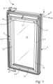
- a schematic drawing of a roof window 1 is shown from an internal, or interior, side.
- the roof window 1 comprises one or more frame structures, typically a stationary frame 3 and a sash 2 carrying a glazing element 4 such as a transparent pane.
- the sash 2 may be openable or fixed.
- Fig. 1 shows an embodiment of a roof window 1 comprising a stationary frame 3 and an openable sash 2.
- the frame structure of the roof window will in the following be represented by the sash 2 which comprises two side members 2.2 and 2.3 extending in a height direction of the roof window 1, here denoted a longitudinal direction L.
- the sash 2 further comprises a top member 2.1 and a bottom member 2.4 extending in a width direction W.
- the width direction W and length direction L define a plane, to which a depth direction D is perpendicular.
- a window opening 5 is thus formed, indicated in Fig. 2A and here defined by the inner sides of the sash members 2.1, 2.2, 2.3, 2.4, and which window opening 5 is to be screened by a roof window screening arrangement 10 according to the invention as will be described in further detail below.
- the screening arrangement 10 may be arranged in the stationary frame 3, such as between two side members of the stationary frame 3.
- the roof window 1 is adapted to be installed in an inclined roof, here by means of a set of frame brackets connected to the stationary frame 3 and of which two representative frame brackets 6 are shown. It is noted that the inclinations indicated throughout the drawings are merely representations and an internal roof window screening arrangement 10 according to the invention may be mounted in a roof window 1 with an inclination different from the one indicated in these embodiments.
- the roof window screening arrangement 10 is shown in a mounted condition in the roof window 1.
- the screening arrangement 10 comprises two side rails 12, 13 connected to respective sash side members 2.2, 2.3.
- the side rail 13 is here a mirror version of side rail 12 and the two side rails 12, 13 are mounted in the same manner.
- detailed reference only to the right-hand side rail 12 will be made; it is to be understood that any features relating to the side rail 12 apply to the opposite side rail 13 as well.
- each side rail 12, 13 each extends by its length extension in the longitudinal direction L in the mounted condition of the screening arrangement 10.
- each side rail 12, 13 has a side rail front 12.2 having a width dimension extending in parallel with the plane in the mounted condition, and a leg portion 12.3 extending at an angle to the side rail front 12.2, for instance at substantially right angles, that is, in the depth direction D.
- the precise angle depends on the configuration of the sash 2, which in some roof windows may have a slight inclination.
- the side rails 12, 13 are also provided with engagement means to be described in further detail below.
- the screening arrangement additionally comprises a top element 11 extending between the two side members 2.2 and 2.3 in proximity of the top member 2.1 as shown in Fig. 1 .
- the top element 11 may comprise a front cover 11.1 as indicated, a back cover and two end pieces, with one end piece arranged at each end of the top element 11 as is known in the art, to be connected to mounting bracket which in some types of roof windows are pre-mounted on the side members 2.2, 2.3.
- the side rail 12 is connected to the side member 2.2 partly by means of a connection part 20, partly indirectly via the top element 11 of the screening arrangement 10.
- another connection part 20 is mounted on the other sash side member 2.3 to provide the connection of the side rail 13 to the side member 2.3 of the sash 2 in the mounted condition of the screening arrangement 10.
- Fig. 2A shows the side rail 12 being attached to the top element 11 by a hinge connection comprising a connection arm 7.
- a hinge connection comprising a connection arm 7.
- the side rail 12 is configured to assume a first position at an angle relative to the plane in an assembly condition and a second position parallel to the plane. In the second position the side rail 2.2 is attached to the side member 2.2 of the frame structure to obtain the mounted condition.
- the screening arrangement 10 additionally comprises a screening body 15 having two side edges and a predefined length between a first end portion and a second end portion.
- the screening body 15 is movable in the longitudinal direction L between a non-screening position and a screening position in which the screening body 15 substantially covers the glazing element 4.
- the screening body 15 In the non-screening position, the screening body 15 is configured to be accommodated in the top element 11 as indicated in Fig. 2A .
- the window opening 5 covered by the glazing element 4 is in turn covered by the screening body 15.
- a bottom profile 14 is provided to extend substantially in parallel with the top element 11 and is connected to the second end portion of the screening body 15.
- the screening arrangement 10 of the present embodiment is a roller blind, in which the screening body 15 has shading or light-dampening properties and which at its upper end is fastened to a spring-biased roller shaft (not shown) in the top element. As a consequence, the screening body 15 and the bottom profile 14 are biased to move towards the top element 11 in the screening position.
- each side rail 12, 13 is attached to the sash 2 solely by means of a respective set of connection parts 20.
- two connection parts 20 are placed at a distance from each other in the longitudinal direction L.
- the side rails 12, 13 are connected to the respective side member 2.2, 2.3 of the sash by moving the side rails 12, 13 in the depth direction D.
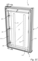
- the embodiment of Fig. 2C makes use of a set of three connection parts 20, and the side rails 12, 13 are moved in parallel with the depth direction D for mounting.
- connection parts 20 may be provided to connect each side rail 12, 13 to the respective side member 2.2, 2.3. This is particularly advantageous in the case of tall roof windows, in which the side rails 12, 13 have a substantial extension in the longitudinal direction L.
- connection part 20 and the engagement with the side rails 12, 13 will be described in more detail with particular reference to Figs. 3 and 4 .
- connection part 20 comprises an adhesive portion 21 on the face adapted to be positioned on a plane surface of the side member 2.2.
- the adhesive portion 21 is typically covered by a sacrificial liner 21a which is removed prior to placing the connection part 20 with the adhesive portion 21 on the side members 2.2, 2.3 of the sash 2.
- the connection part 20 is typically formed as a moulded plastic component to result in a flexible, thin-walled element to which the adhesive portion 21 is applied.
- connection part 20 comprises engagement means 22 adapted to engage with the side rails 12, 13 to obtain the mounted condition by means of counterpart engagement means of the side rails 12, 13 in such a way that the side rail 12, 13 is freely slidable in the longitudinal direction L when engaged with the connection part 20.
- the connection part 20 can be attached to the side member 2.2, 2.3 at substantially any point in the longitudinal direction L of the side member 2.2, 2.3.
- the freely slidable connection means that the engagement means 22 of connection part 20 will only transfer a minimum of forces to the adhesive portion 21 during operation of the screening arrangement 10.
- the engagement means 22 comprise an engagement tongue 221 of a tab 222 connected to a central portion of the connection part 20.
- the tab 222 is connected to the central portion of the connection part 20 by means of a resilient suspension ring 223.
- the engagement tongue 221 is configured to be introduced into the counterpart engagement means of the side rail 12, which is here formed as a track 12.1 extending in the longitudinal direction L.
- the track 12.1 is provided within the leg portion 12.3 of the side rail 12 in that the leg portion 12.3 comprises two track members 12.i with two track retainers 12.1ii delimiting a track opening facing an interior edge of the connection part 20 in the depth direction D, when bringing the side rail 12 towards the connection part 20,
- the track 12.1 is placed opposite the engagement means 22 and subsequent movement of the side rail 12 in the depth direction entails that the engagement tongue 221 of the connection part 20 is inserted between the track retainers 12.1 ii and enters the track 12.1.
- the engagement between the side rail 12, 13 and the connection part 20 is advantageously releasable.
- the engagement means 22 comprise a snap-lock mechanism to lockingly engage the connection part 20 with the side rail 12 in the mounted condition, but which may be released by pressing the tab 222 thereby releasing the engagement between the engagement tongue 221 and the track 12.1 and withdrawing the side rail 12, 13 in the opposite direction.
- the snap-lock mechanism makes it possible to simply push the side rail over the connection part to allow the engagement means of the connection part to engage with the counterpart engagement means of the side rail. Conversely, in case it is desired to release the side rail, the snap-lock mechanism is deactivated, and the side rail simply pulled out of engagement with the connection part.
- the snap-lock mechanism is here of the type in which the engagement is automatically, or directly, activated when pushing the side rail 12, 13 over the engagement means 22 of the connection part 20.
- the engagement means are manually deactivated as described in the above, by pressing the tab 222 to release the engagement tongue 221, and then pull the side rail 12, 13 out of engagement with the connection part 20.
- the snap engagement as a force-locking structure, in which the engagement is dependent on frictional contact between the engagement means of the connection part and the side rail, respectively, and which is overcome by applying a sufficient force pulling the side rail out of engagement.
- FIG. 4 Further details of the side rail 12 shown in Fig. 4 include openings 12.4 and 12.6, and a track plate 12.5 having functions in connecting the connection arm 7 of the embodiment of Figs. 1 and 2A to the side rails 12, 13.
- the openings 12.4 and 12.6 have a function in such embodiments in which the connection arm 7 is associated to a spring assembly providing a bias in the longitudinal direction L in the mounted condition of the screening arrangement 10.
- a spring assembly may constitute one of a plurality of possibilities for a side rail suspension system.
- the side rail suspension system ensures that the side rail is fixated, or fastened, in the longitudinal direction L in the mounted condition.
- Other conceivable possibilities include a spring assembly at the bottom of the side rail, either located within the side rail 12, 13 to provide a compression mount relative to the bottom member 2.4 of the sash 2, or as a separate foot member attached to the bottom member 2.4 and/or the adjacent side member 2.2 or 2.3, which in turn secures the side rail 12, 13.
- Corresponding configurations are applicable at the top in screening arrangements without a top element.
- the side rail 12, 13 may be lodged behind a front of the top element 11, i.e. on the exterior side of such a front.
- a mounting sequence of a connection part 20 and the side rail 13 at the side member 2.3 of the sash 2 is shown in Figs. 5 to 7 .
- a mounting template 30 is provided for retention and positioning of the connection part 20 on the side member 2.3 prior to adhering the connection part 20 to the side member.
- the mounting template 30 is adapted to releasably retain the connection part 20 at a distance from the side frame member 2.3 when the mounting template 30 is in abutment with the side frame member 2.3 but before the retention is released.
- Blocking means 36 limit the releasable retainment to the direction of the surface of the side member 2.3.
- First guiding means are provided in the form of guiding sections 38.
- Second guiding means are here provided in the form of two spacing sections 39 formed as substantially planar sections at either side of an opening 34 so that the mounting template 30 is movable in the longitudinal direction L until it abuts the bottom member 2.4 of the sash 2. Subsequent release of the connection part 20 from the mounting template 30 results in the position of Fig. 6 . Connection of the side rail 12 substantially as described in the above results in the position shown in Fig.
- connection means 22 of the connection part 20 is shown in the view from the exterior of in Fig. 8 .
- the mounting template 30 in the embodiment shown comprises a finger grip section 35.
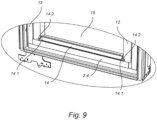
- Fig. 9 Details of a further embodiment are shown in Fig. 9 , in which the bottom profile 14 is configured to interact with the side rails 12, 13 by means of a guide element 14.1 at each longitudinal end of the bottom profile 14.
- Each guide element 14.1 is provided with a guide element nose 14.2 configured to slide along the side rail front 12.2 of the side rail 12, 13. In this way, it is ensured that the bottom profile 14 and the screening body 15 are not moved involuntary towards the glazing element 14. This is particularly advantageous in such embodiments in which the side rails 12, 13 do not comprise a guide track.
- an end stop 14.3 is provided.
- the presence of an end stop 14.3 to interact with one or both ends of the bottom profile 14 is particularly advantageous in the case of a spring-biased roller blind as described in connection with the embodiment of Figs. 1 and 2A , since the end stop or end stops 14.3 efficiently counteract(s) the movement towards the top element 11.
- FIG. 10 A more detailed view of the engagement between the engagement means 22 of the connection part 20 and the counterpart engagement means of the side rails 12, 13 is shown in Fig. 10 , here for the side rail 13.
- connection part 20 is attached to an inwards facing surface of the side member 2.3 substantially as described in the above. It is noted that the inwards-facing surface is provided with a slight inclination relative to the depth direction D such that the window opening 5 area increases from the glazing element 4 towards the interior.
- the resilient suspension ring 223 with the tab 222 and engagement tongue 221 of the engagement means 22 protrude from the general plane of the connection part 20, which is parallel to the inwards-facing surface of the sash member, in the width direction W.
- the engagement means 22 have an extension in the depth direction D namely such that engagement tongue 221 in the embodiment shown is located beyond an outer circumference of the adhesive portion 21 and the periphery of the remaining portions of the connection part 20.
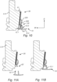
- connection part 20 is provided with substantially T-shaped engagement means 22'.
- side rail 13 is provided with an opening 12.7 (corresponding in substance to openings 12.4 and 12.6 as shown in Fig. 4 ) such that the side rail 13 may be moved over the engagement means 22' in the depth direction D, following which the side rail 13 is moved in the longitudinal direction L such that the head of the T engages with the track retainers 12.1ii. This presupposes that there is room for moving the side rails 12, 13 within the window opening 5 or on the sash 2.
- FIGs. 12A and 12B A further alternative embodiment is shown in Figs. 12A and 12B , in which the engagement means of the side rail 13 is provided as a track 12.8 on a side of the leg portion 12.3, with a track opening facing the connection part 20 in the width direction W.
- the engagement means 22" of the connection part 20 protrude in the width direction W and are schematically illustrated as a flexible hook to enter the track 12.8.
- the leg portion 12.3 is provided with a guide track 12.9 facing the screening body 15 and configured to guide a side edge of the screening body 15.
- connection part 20 Referring now Figs. 13 to 19 , the configuration of the adhesive portion 21 and the relationship of the engagement means 22 and the attachment or fastening thereof to the remaining portions of the connection part 20 will be described in more detail.
- the adhesive portion 21 of the connection part 20 has a predefined outer circumference
- the engagement means 22 of the connection part 20 are provided at a distance from the predefined outer circumference. This has proven to be instrumental in preventing the adhesive portion 21 from peeling during use.
- the engagement means 22 are advantageously provided such that the active engagement part, i.e. for instance the engagement tongue 221 in the embodiments comprising a resilient suspension ring 223 with the tab 222 and engagement tongue 221, is provided at some distance from the attachment location of the resilient suspension ring 223 to the remaining, plane portions of the connection part 20 and the adhesive portion 21.
- the dimensions and the shape of the adhesive portion 21 is important as well. Exemplary configurations are shown in Figs. 13 to 19 .
- the predefined outer circumference of the adhesive portion 21 may in principle assume any shape but the shown substantially rectangular or elliptic shapes are advantageous from a number of reasons, not least from a user perspective, since the connection parts 20 with respective adhesive portions 21 will most often be partially visible.
- the adhesive portion 21 may be a coherent adhesive portion having the substantially the same surface area as the overall connection part 20, or on part of the area of the connection part 20, or larger than the area of the connection part 20. It is also conceivable to form the adhesive portion in two or more parts, for instance such that one connection part 20 comprises two adhesive portions 21 at a distance from each other. Here, it is shown that the engagement means 22 are provided in a gap between neighbouring adhesive portions 21.
- the engagement means 22 may have such an extension that they protrude beyond the outer circumference of the adhesive portion or be provided within the outer circumference.
Landscapes
- Engineering & Computer Science (AREA)
- Architecture (AREA)
- Civil Engineering (AREA)
- Structural Engineering (AREA)
- Wing Frames And Configurations (AREA)
Abstract
The internal screening arrangement (10) is intended to be mounted on a frame structure (2) of a roof window. The screening arrangement (10) comprises two side rails (12, 13) and at least one connection part (20) for each side rail (12, 13). The connection part (20) comprises an adhesive portion (21) by which the connection part (20) is adapted to be mounted on the side member (2.2, 2.3). The connection part (20) comprises engagement means (22) adapted to engage with engagement means (12.1) of the side rail (12, 13) to obtain the mounted condition, such that the side rail (12, 13) is freely slidable in the longitudinal direction (L) when engaged with the connection part (20).
Description
- The present invention relates to an internal roof window screening arrangement for a roof window, the roof window having a frame structure comprising a top member and a bottom member extending in a width direction and two mutually parallel side members extending in a longitudinal direction, the width direction and longitudinal direction defining a plane, the screening arrangement comprising two side rails and at least one connection part for each side rail, each side rail being adapted to be mounted on a side member of the frame structure by means of the at least one connection part to obtain a mounted condition.
- Such internal screening arrangements provided for screening of windows installed in a roof are typically brought from the supply condition to the mounted condition on the frame structure of the roof window by a user not necessarily possessing craftsperson skills. Since the roof window is by nature provided in an inclined position, generally in a clearing in an inclined inner wall, mounting of such screening arrangements is particularly challenging. The inclined position also poses challenges in use, since all components of the screening arrangement will be subjected to gravity, the resulting force of which will most often be directed into the interior of the room of the building in which the roof window is installed. The fixing of the side rails to the frame structure of the roof window traditionally takes place by the use of fastening means such as screws or other elements interacting with the frame structure to retain the screening arrangement safely to the frame structure in the mounted condition. While the use of such fastening means allow for easy mounting and secure fastening of the side rails, they typically also result in damage of the roof window itself, which is not desirable.
- In the prior art, several attempts have been made to address the inconveniences inherent in such fastening means. While some solutions that provide somewhat satisfactory results have been devised, there is still room for improvement.
- With this background, it is therefore an object of the invention to provide an improved internal roof window screening arrangement which at the same time allows for an easy mounting procedure and which provides satisfactory performance in use.
- This and further objects are achieved with an internal roof window screening arrangement of the kind mentioned in the introduction which is furthermore characterised in that the connection part comprises an adhesive portion, in that the connection part is adapted to be mounted on the side member by means of said adhesive portion, and in that the connection part comprises engagement means adapted to engage with engagement means of the side rail to obtain the mounted condition, such that the side rail is freely slidable in the longitudinal direction when engaged with the connection part.
- By providing connection of the side rail by means of the adhesive portion, it is ensured that the risk of damage to the roof window itself is minimised. Thus, in case the screening arrangement needs to be removed, for instance when moving from rental lodging, the roof window remains substantially intact. In principle, the side rail could be connected to the side member with any number of connection parts, for instance two located at a distance from one another, or combined with connection with a top element, if present, of the screening arrangement.
- The freely slidable connection between the engagement means of the connection part and the engagement means of the side rail in the mounted condition entails that only a fraction of the forces that occur during use of the screening arrangement are not transferred to the connection part. Hence, the adhesive portion is able to remain substantially unaffected and thus intact.
- By the term "freely slidable" is to be understood that the engagement means of the connection part are only or mainly configured to provide support to the side rail in the depth and width directions, but not in the longitudinal direction. In other words, any load acting on the side rail will only be transferred to the connection part in the form of frictional forces, which are typically minimal. This is particularly relevant in case of roller blinds having a spring-biased roller shaft, such that side rail will experience a substantially constant tension in the screening position, but also in other types of screening arrangements, in which any operating elements such as a bottom and/or top profile connected to ends of the screening body affect the side rail while being moved.
- Other presently preferred embodiments and further advantages will be apparent from the subsequent detailed description and drawings.
- In the following description embodiments of the invention will be described with reference to the schematic drawings, in which
-
Fig. 1 is a perspective view of a roof window with a mounted internal roof window screening arrangement in a general embodiment of the invention; -
Fig. 2A is a perspective view of a roof window with the screening arrangement ofFig. 1 in an assembly condition; -
Fig. 2B is a view corresponding toFig. 2A of another embodiment; -
Fig. 2C is a view corresponding toFig. 2A of a further embodiment; -
Fig. 3 is a perspective view of a connection part in an embodiment of the screening arrangement of the invention; -
Fig. 4 is a partial perspective view of a side rail of a screening arrangement according to an embodiment of the invention; -
Fig. 5 is a partial perspective view of a connection part of an embodiment of the screening arrangement according to the invention during mounting on a side member of a sash of a roof window by means of a mounting template; -
Fig. 6 is a view corresponding toFig. 5 , showing the connection part in a mounted condition; -
Fig. 7 is a view corresponding toFig. 6 , showing a side rail of the screening arrangement connected to the connection part; -
Fig. 8 is a view of the details ofFig. 7 , shown from a different angle; -
Fig. 9 shows a detailed partial view of the bottom of the roof window ofFig. 1 ; -
Fig. 10 is a cross-sectional view showing a connection part of a screening arrangement in an embodiment of the invention, mounted on a side member of the sash and connected to a side rail; -
Figs. 11A and 11B show schematic cross-sectional views of a connection part and a side rail of a screening arrangement in an alternative embodiment of the invention; -
Figs. 12A and 12B show schematic cross-sectional views of a connection part and a side rail of a screening arrangement in a further alternative embodiment of the invention; and -
Figs. 13 to 19 show schematic views of various embodiments of the adhesive portion and the engagement means of the connection part. - In the following detailed description, preferred embodiments of the present invention will be described. However, it is to be understood that features of the different embodiments are exchangeable between the embodiments and may be combined in different ways, unless anything else is specifically indicated. It may also be noted, for the sake of clarity, that the dimensions of certain components illustrated in the drawings may differ from the corresponding dimensions in real-life implementations.
- It is noted that terms such as "up", "down", "left-hand", "right-hand", "exterior", "interior", "outer", "inner" are relative and refers to the viewpoint in question. In general, when referred to an exterior side, this relates to a side of the roof window and/or screening arrangement in the mounted condition facing the outdoors or external side of the building. Conversely, an interior side refers to a side facing the internal side of the building, i.e. typically a subjacent room including any light shaft. Terms such as "outwards" and "inwards" are directions generally perpendicular to an interior-exterior direction, taking as its base point a centre of the roof window.
- Throughout the embodiments, elements having the same or analogous function are denoted by the same reference numerals. Only differences will be described in detail.
- Referring initially to
Figs. 1 and2A , a schematic drawing of aroof window 1 is shown from an internal, or interior, side. Typically, theroof window 1 comprises one or more frame structures, typically astationary frame 3 and asash 2 carrying aglazing element 4 such as a transparent pane. Thesash 2 may be openable or fixed.Fig. 1 shows an embodiment of aroof window 1 comprising astationary frame 3 and anopenable sash 2. The frame structure of the roof window will in the following be represented by thesash 2 which comprises two side members 2.2 and 2.3 extending in a height direction of theroof window 1, here denoted a longitudinal direction L. Thesash 2 further comprises a top member 2.1 and a bottom member 2.4 extending in a width direction W. The width direction W and length direction L define a plane, to which a depth direction D is perpendicular. Awindow opening 5 is thus formed, indicated inFig. 2A and here defined by the inner sides of the sash members 2.1, 2.2, 2.3, 2.4, and which window opening 5 is to be screened by a roofwindow screening arrangement 10 according to the invention as will be described in further detail below. In roof windows without a sash frame structure, thescreening arrangement 10 may be arranged in thestationary frame 3, such as between two side members of thestationary frame 3. - The
roof window 1 is adapted to be installed in an inclined roof, here by means of a set of frame brackets connected to thestationary frame 3 and of which tworepresentative frame brackets 6 are shown. It is noted that the inclinations indicated throughout the drawings are merely representations and an internal roofwindow screening arrangement 10 according to the invention may be mounted in aroof window 1 with an inclination different from the one indicated in these embodiments. - In
Fig. 1 , the roofwindow screening arrangement 10 is shown in a mounted condition in theroof window 1. Thescreening arrangement 10 comprises twoside rails side rail 13 is here a mirror version ofside rail 12 and the twoside rails hand side rail 12 will be made; it is to be understood that any features relating to theside rail 12 apply to theopposite side rail 13 as well. - Referring briefly also to
Fig. 4 , the twoside rails screening arrangement 10. As shown forside rail 12 inFig. 4 , eachside rail sash 2, which in some roof windows may have a slight inclination. The side rails 12, 13 are also provided with engagement means to be described in further detail below. When referring to the side rails 12, 13 being in the mounted condition, i.e. in a position in which eachside rail side rail 12 being attached to the side member 2.2 of thesash 2 and theside rail 13 to the other side member 2.3. - In the embodiment shown in
Figs. 1 and2A , the screening arrangement additionally comprises atop element 11 extending between the two side members 2.2 and 2.3 in proximity of the top member 2.1 as shown inFig. 1 . Thetop element 11 may comprise a front cover 11.1 as indicated, a back cover and two end pieces, with one end piece arranged at each end of thetop element 11 as is known in the art, to be connected to mounting bracket which in some types of roof windows are pre-mounted on the side members 2.2, 2.3. - In this embodiment, the
side rail 12 is connected to the side member 2.2 partly by means of aconnection part 20, partly indirectly via thetop element 11 of thescreening arrangement 10. Correspondingly, anotherconnection part 20 is mounted on the other sash side member 2.3 to provide the connection of theside rail 13 to the side member 2.3 of thesash 2 in the mounted condition of thescreening arrangement 10. -
Fig. 2A shows theside rail 12 being attached to thetop element 11 by a hinge connection comprising aconnection arm 7. This provides a secure attachment of thescreening arrangement 10 to theroof window 1 without the need of screws, nails or other fastening means that break the surface of the side member 2.3. In these embodiments, theside rail 12 is configured to assume a first position at an angle relative to the plane in an assembly condition and a second position parallel to the plane. In the second position the side rail 2.2 is attached to the side member 2.2 of the frame structure to obtain the mounted condition. - The
screening arrangement 10 additionally comprises ascreening body 15 having two side edges and a predefined length between a first end portion and a second end portion. Thescreening body 15 is movable in the longitudinal direction L between a non-screening position and a screening position in which thescreening body 15 substantially covers theglazing element 4. In the non-screening position, thescreening body 15 is configured to be accommodated in thetop element 11 as indicated inFig. 2A . InFig. 1 , thewindow opening 5 covered by theglazing element 4 is in turn covered by thescreening body 15. To operate thescreening body 15 of thescreening arrangement 10, abottom profile 14 is provided to extend substantially in parallel with thetop element 11 and is connected to the second end portion of thescreening body 15. Thescreening arrangement 10 of the present embodiment is a roller blind, in which thescreening body 15 has shading or light-dampening properties and which at its upper end is fastened to a spring-biased roller shaft (not shown) in the top element. As a consequence, thescreening body 15 and thebottom profile 14 are biased to move towards thetop element 11 in the screening position. - In comparison, in the embodiments of
Figs. 2B and2C , no top element is present and eachside rail sash 2 solely by means of a respective set ofconnection parts 20. In the embodiment ofFig. 2B , twoconnection parts 20 are placed at a distance from each other in the longitudinal direction L. During mounting, the side rails 12, 13 are connected to the respective side member 2.2, 2.3 of the sash by moving the side rails 12, 13 in the depth direction D. The embodiment ofFig. 2C makes use of a set of threeconnection parts 20, and the side rails 12, 13 are moved in parallel with the depth direction D for mounting. It is noted that also in such embodiments which make use of atop element 11, two ormore connection parts 20 may be provided to connect eachside rail - In the following, the configuration of the
connection part 20 and the engagement with the side rails 12, 13 will be described in more detail with particular reference toFigs. 3 and4 . - The
connection part 20 comprises anadhesive portion 21 on the face adapted to be positioned on a plane surface of the side member 2.2. In a supply condition, theadhesive portion 21 is typically covered by asacrificial liner 21a which is removed prior to placing theconnection part 20 with theadhesive portion 21 on the side members 2.2, 2.3 of thesash 2. Theconnection part 20 is typically formed as a moulded plastic component to result in a flexible, thin-walled element to which theadhesive portion 21 is applied. - The
connection part 20 comprises engagement means 22 adapted to engage with the side rails 12, 13 to obtain the mounted condition by means of counterpart engagement means of the side rails 12, 13 in such a way that theside rail connection part 20. In principle, theconnection part 20 can be attached to the side member 2.2, 2.3 at substantially any point in the longitudinal direction L of the side member 2.2, 2.3. At the same time, the freely slidable connection means that the engagement means 22 ofconnection part 20 will only transfer a minimum of forces to theadhesive portion 21 during operation of thescreening arrangement 10. - In the embodiments shown in
Figs. 3 and4 , the engagement means 22 comprise anengagement tongue 221 of atab 222 connected to a central portion of theconnection part 20. Thetab 222 is connected to the central portion of theconnection part 20 by means of aresilient suspension ring 223. Theengagement tongue 221 is configured to be introduced into the counterpart engagement means of theside rail 12, which is here formed as a track 12.1 extending in the longitudinal direction L. The track 12.1 is provided within the leg portion 12.3 of theside rail 12 in that the leg portion 12.3 comprises two track members 12.i with two track retainers 12.1ii delimiting a track opening facing an interior edge of theconnection part 20 in the depth direction D, when bringing theside rail 12 towards theconnection part 20, - To obtain the mounted condition of the
side rail 12, the track 12.1 is placed opposite the engagement means 22 and subsequent movement of theside rail 12 in the depth direction entails that theengagement tongue 221 of theconnection part 20 is inserted between the track retainers 12.1 ii and enters the track 12.1. - The engagement between the
side rail connection part 20 is advantageously releasable. Here, the engagement means 22 comprise a snap-lock mechanism to lockingly engage theconnection part 20 with theside rail 12 in the mounted condition, but which may be released by pressing thetab 222 thereby releasing the engagement between theengagement tongue 221 and the track 12.1 and withdrawing theside rail - The snap-lock mechanism makes it possible to simply push the side rail over the connection part to allow the engagement means of the connection part to engage with the counterpart engagement means of the side rail. Conversely, in case it is desired to release the side rail, the snap-lock mechanism is deactivated, and the side rail simply pulled out of engagement with the connection part.
- The snap-lock mechanism is here of the type in which the engagement is automatically, or directly, activated when pushing the
side rail connection part 20. In order to release the engagement, the engagement means are manually deactivated as described in the above, by pressing thetab 222 to release theengagement tongue 221, and then pull theside rail connection part 20. - As an alternative, it is conceivable to form the snap engagement as a force-locking structure, in which the engagement is dependent on frictional contact between the engagement means of the connection part and the side rail, respectively, and which is overcome by applying a sufficient force pulling the side rail out of engagement.
- Further details of the
side rail 12 shown inFig. 4 include openings 12.4 and 12.6, and a track plate 12.5 having functions in connecting theconnection arm 7 of the embodiment ofFigs. 1 and2A to the side rails 12, 13. - In particular, the openings 12.4 and 12.6 have a function in such embodiments in which the
connection arm 7 is associated to a spring assembly providing a bias in the longitudinal direction L in the mounted condition of thescreening arrangement 10. Such a spring assembly may constitute one of a plurality of possibilities for a side rail suspension system. The side rail suspension system ensures that the side rail is fixated, or fastened, in the longitudinal direction L in the mounted condition. Other conceivable possibilities include a spring assembly at the bottom of the side rail, either located within theside rail sash 2, or as a separate foot member attached to the bottom member 2.4 and/or the adjacent side member 2.2 or 2.3, which in turn secures theside rail top element 11, theside rail top element 11, i.e. on the exterior side of such a front. - A mounting sequence of a
connection part 20 and theside rail 13 at the side member 2.3 of thesash 2 is shown inFigs. 5 to 7 . To facilitate mounting of theconnection part 20 to the side member 2.3, a mountingtemplate 30 is provided for retention and positioning of theconnection part 20 on the side member 2.3 prior to adhering theconnection part 20 to the side member. The mountingtemplate 30 is adapted to releasably retain theconnection part 20 at a distance from the side frame member 2.3 when the mountingtemplate 30 is in abutment with the side frame member 2.3 but before the retention is released. Blocking means 36 limit the releasable retainment to the direction of the surface of the side member 2.3. First guiding means are provided in the form of guidingsections 38. Each guidingsection 38 grips around an edge of the side member 2.3, thereby restricting movement towards the exterior side of the roof window, and ensures that when theconnection part 20 is released from the mountingtemplate 30, theconnection part 20 is placed on the side member 2.3 at the correct depth and in the correct distance from theglazing element 4. Second guiding means are here provided in the form of two spacingsections 39 formed as substantially planar sections at either side of anopening 34 so that the mountingtemplate 30 is movable in the longitudinal direction L until it abuts the bottom member 2.4 of thesash 2. Subsequent release of theconnection part 20 from the mountingtemplate 30 results in the position ofFig. 6 . Connection of theside rail 12 substantially as described in the above results in the position shown inFig. 7 , the interaction between the connection means 22 of theconnection part 20 and the track 12.1i forming the counterpart connection means of theside rail 13 is shown in the view from the exterior of inFig. 8 . A further detail is that the mountingtemplate 30 in the embodiment shown comprises afinger grip section 35. - Following mounting of the
screening arrangement 10 substantially as described in the above, thescreening arrangement 10 is ready for use. Details of a further embodiment are shown inFig. 9 , in which thebottom profile 14 is configured to interact with the side rails 12, 13 by means of a guide element 14.1 at each longitudinal end of thebottom profile 14. Each guide element 14.1 is provided with a guide element nose 14.2 configured to slide along the side rail front 12.2 of theside rail bottom profile 14 and thescreening body 15 are not moved involuntary towards theglazing element 14. This is particularly advantageous in such embodiments in which the side rails 12, 13 do not comprise a guide track. To provide an end stop for thebottom profile 14 in order to allow thescreening body 15 to be parked in the fully screening position, an end stop 14.3 is provided. The presence of an end stop 14.3 to interact with one or both ends of thebottom profile 14 is particularly advantageous in the case of a spring-biased roller blind as described in connection with the embodiment ofFigs. 1 and2A , since the end stop or end stops 14.3 efficiently counteract(s) the movement towards thetop element 11. - A more detailed view of the engagement between the engagement means 22 of the
connection part 20 and the counterpart engagement means of the side rails 12, 13 is shown inFig. 10 , here for theside rail 13. - The
adhesive portion 21 of theconnection part 20 is attached to an inwards facing surface of the side member 2.3 substantially as described in the above. It is noted that the inwards-facing surface is provided with a slight inclination relative to the depth direction D such that thewindow opening 5 area increases from theglazing element 4 towards the interior. Theresilient suspension ring 223 with thetab 222 andengagement tongue 221 of the engagement means 22 protrude from the general plane of theconnection part 20, which is parallel to the inwards-facing surface of the sash member, in the width direction W. As is also apparent, the engagement means 22 have an extension in the depth direction D namely such thatengagement tongue 221 in the embodiment shown is located beyond an outer circumference of theadhesive portion 21 and the periphery of the remaining portions of theconnection part 20. - An alternative engagement form is shown in
Figs. 11A and 11B , in which theconnection part 20 is provided with substantially T-shaped engagement means 22'. Correspondingly, theside rail 13 is provided with an opening 12.7 (corresponding in substance to openings 12.4 and 12.6 as shown inFig. 4 ) such that theside rail 13 may be moved over the engagement means 22' in the depth direction D, following which theside rail 13 is moved in the longitudinal direction L such that the head of the T engages with the track retainers 12.1ii. This presupposes that there is room for moving the side rails 12, 13 within thewindow opening 5 or on thesash 2. - A further alternative embodiment is shown in
Figs. 12A and 12B , in which the engagement means of theside rail 13 is provided as a track 12.8 on a side of the leg portion 12.3, with a track opening facing theconnection part 20 in the width direction W. The engagement means 22" of theconnection part 20 protrude in the width direction W and are schematically illustrated as a flexible hook to enter the track 12.8. Another detail in this embodiment is that the leg portion 12.3 is provided with a guide track 12.9 facing thescreening body 15 and configured to guide a side edge of thescreening body 15. - Referring now
Figs. 13 to 19 , the configuration of theadhesive portion 21 and the relationship of the engagement means 22 and the attachment or fastening thereof to the remaining portions of theconnection part 20 will be described in more detail. - In general, the
adhesive portion 21 of theconnection part 20 has a predefined outer circumference, and the engagement means 22 of theconnection part 20 are provided at a distance from the predefined outer circumference. This has proven to be instrumental in preventing theadhesive portion 21 from peeling during use. The engagement means 22 are advantageously provided such that the active engagement part, i.e. for instance theengagement tongue 221 in the embodiments comprising aresilient suspension ring 223 with thetab 222 andengagement tongue 221, is provided at some distance from the attachment location of theresilient suspension ring 223 to the remaining, plane portions of theconnection part 20 and theadhesive portion 21. - The dimensions and the shape of the
adhesive portion 21 is important as well. Exemplary configurations are shown inFigs. 13 to 19 . The predefined outer circumference of theadhesive portion 21 may in principle assume any shape but the shown substantially rectangular or elliptic shapes are advantageous from a number of reasons, not least from a user perspective, since theconnection parts 20 with respectiveadhesive portions 21 will most often be partially visible. - The
adhesive portion 21 may be a coherent adhesive portion having the substantially the same surface area as theoverall connection part 20, or on part of the area of theconnection part 20, or larger than the area of theconnection part 20. It is also conceivable to form the adhesive portion in two or more parts, for instance such that oneconnection part 20 comprises twoadhesive portions 21 at a distance from each other. Here, it is shown that the engagement means 22 are provided in a gap between neighbouringadhesive portions 21. - Taking the
specific engagement tongue 221 of the shown engagement means 22 as example, the engagement means 22 may have such an extension that they protrude beyond the outer circumference of the adhesive portion or be provided within the outer circumference. - The invention is not limited to the embodiments shown and described in the above, but various modifications and combinations may be carried out.
-
- 1
- roof window
- 2
- frame structure / sash
- 2.1
- top member
- 2.2
- side member
- 2.3
- side member
- 2.4
- bottom member
- 3
- stationary frame
- 4
- glazing element / pane
- 5
- window opening
- 6
- frame bracket
- 7
- connection arm
- 10
- screening arrangement
- 11
- top element 11.1 front cover
- 12
- side rail
- 12.1 track
- 12.1i track member
- 12.1ii track retainer
- 12.2 side rail front
- 12.3 leg portion
- 12.4 opening
- 12.5 track plate
- 12.6 opening
- 12.7 insertion opening
- 12.8 track
- 12.9 guide track
- 13
- side rail
- 14
- bottom profile
- 14.1 guide element
- 14.2 guide element nose
- 14.3 end stop
- 15
- screening body
- 20
- connection part
- 21
- adhesive portion
- 21a
- sacrificial liner
- 22
- engagement means
- 221 engagement tongue
- 222 tab
- 223 resilient suspension ring
- 22'
- engagement means (alternative embodiment)
- 22"
- engagement means (further alternative embodiment)
- 30
- mounting template
- 34
- opening
- 35
- finger grip section
- 36
- blocking means
- 38
- guiding section
- 39
- spacing section
- L
- longitudinal direction
- W
- width direction
- D
- depth direction
Claims (15)
- An internal roof window screening arrangement (10) for a roof window (1), the roof window (1) having a frame structure (2) comprising a top member (2.1) and a bottom member (2.4) extending in a width direction (W) and two mutually parallel side members (2.2, 2.3) extending in a longitudinal direction (L), the width direction (W) and longitudinal direction (L) defining a plane,the screening arrangement (10) comprising two side rails (12, 13) and at least one connection part (20) for each side rail (12, 13), each side rail (12, 13) being adapted to be mounted on a side member (2.2, 2.3) of the frame structure (2) by means of the at least one connection part (20) to obtain a mounted condition,characterised in thatthe connection part (20) comprises an adhesive portion (21),in that the connection part (20) is adapted to be mounted on the side member (2.2, 2.3) by means of said adhesive portion (21),and in that the connection part (20) comprises engagement means (22; 22'; 22") adapted to engage with engagement means (12.1; 12.8) of the side rail (12, 13) to obtain the mounted condition, such that the side rail (12, 13) is freely slidable in the longitudinal direction (L) when engaged with the connection part (20).
- An internal roof window screening arrangement (10) according to claim 1, wherein the engagement between the engagement means (22; 22'; 22") of the connection part (20) and the engagement means (12.1; 12.8) of the side rail (12, 13) is releasable.
- An internal roof window screening arrangement (10) according to claim 2, wherein the engagement means comprise a snap-lock mechanism (22; 22") or a bayonet coupling (22'), preferably of the engagement means of the connection part (20).
- An internal roof window screening arrangement (10) according to any one of the preceding claims, wherein the engagement means of the side rail (12, 13) comprises a track (12.1; 12.8) extending in the longitudinal direction (L).
- An internal roof window screening arrangement (10) according to any one of the preceding claims, wherein each side rail (12, 13) comprises a side rail front (12.2) configured to extend substantially in parallel with said plane and a leg portion (12.3) extending at an angle to the side rail front (12.2), preferably at substantially right angles, in the depth direction (D).
- An internal roof window screening arrangement (10) according to claims 4 and 5, wherein the track (12.1) is provided within the leg portion (12.3), the leg portion (12.3) comprising two track members (12.i) with two track retainers (12.1ii) delimiting a track opening facing an interior edge of the connection part (20) in the depth direction (D), in the mounted condition of the side rail (12, 13).
- An internal roof window screening arrangement (10) according to claims 4 and 5, wherein the track is provided as a track (12.8) on a side of the leg portion (12.3) with a track opening facing the connection part (20) in the width direction (W).
- An internal roof window screening arrangement (10) according to any one of claims 5 to 7, wherein the leg portion (12.3) is provided with a guide track (12.9) facing a screening body (15) and configured to guide a side edge of the screening body (15).
- An internal roof window screening arrangement (10) according to any one of the preceding claims, wherein the adhesive portion (21) of the connection part (20) has a predefined outer circumference, and wherein the engagement means (22) of the connection part (20) are provided at a distance from the predefined outer circumference.
- An internal roof window screening arrangement (10) according to claim 9, wherein the predefined outer circumference of the adhesive portion is substantially rectangular or elliptic.
- An internal roof window screening arrangement (10) according to claim 9 or 10, wherein the connection part (20) comprises at least two adhesive portions (21) at a distance from each other, the engagement means (22) being preferably provided in a gap between neighbouring adhesive portions (21).
- An internal roof window screening arrangement (10) according to any one of claims 9 to 11, wherein the engagement means (22) comprise an engagement tongue (221) of a tab (222) connected to a central portion of the connection part (20), and wherein the tab (222) is connected to the central portion of the connection part (20) by means of a resilient suspension ring (223).
- An internal roof window screening arrangement (10) according to any one of the preceding claims, wherein a set of at least two connection parts (20) is configured to be mounted on each side member (2.2, 2.3) of the sash (2) at a distance from each other in the longitudinal direction (L), and wherein each side rail (12, 13) is configured to be connected to the connection parts (20) of the respective set such that the connection parts (20) constitute the sole connection means of the side rails (12, 13) to the respective side member (2.2, 2.3).
- An internal roof window screening arrangement (10) according to any one of claims 1 to 12, wherein the screening arrangement (10) comprises a top element (11), and wherein each side rail (12, 13) is connected to the top element (11) by means of a hinge connection comprising a connection arm (7) and to the side member (2.2, 2.3) of the sash (2) by means of at least one connection part (20) positioned at a distance from the top element (11).
- An internal roof window screening arrangement (10) according to any one of the preceding claims, wherein the screening arrangement comprises a screening body (15) and a bottom profile (14), wherein the bottom profile (14) is configured to interact with the side rails (12, 13) by means of a guide element (14.1) at each longitudinal end of the bottom profile, and wherein each guide element (14.1) is provided with a guide element nose (14.2) configured to slide along a side rail front (12.2) of the side rail (12, 13).
Applications Claiming Priority (3)
| Application Number | Priority Date | Filing Date | Title |
|---|---|---|---|
| DKPA202370310 | 2023-06-19 | ||
| DKPA202370309 | 2023-06-19 | ||
| DKPA202370438 | 2023-08-25 |
Publications (1)
| Publication Number | Publication Date |
|---|---|
| EP4481132A1 true EP4481132A1 (en) | 2024-12-25 |
Family
ID=91586064
Family Applications (1)
| Application Number | Title | Priority Date | Filing Date |
|---|---|---|---|
| EP24182910.0A Pending EP4481132A1 (en) | 2023-06-19 | 2024-06-18 | An internal roof window screening arrangement with a connection part comprising engagement means for engagement with a side rail |
Country Status (1)
| Country | Link |
|---|---|
| EP (1) | EP4481132A1 (en) |
Citations (3)
| Publication number | Priority date | Publication date | Assignee | Title |
|---|---|---|---|---|
| US7690607B2 (en) * | 2007-08-29 | 2010-04-06 | Hunter Douglas Industries Bv | Bracket for mounting a guiding rail |
| US9512673B2 (en) * | 2012-02-29 | 2016-12-06 | Ideas By Design Ltd. | Apparatus for mounting a screen guide rail |
| US20200300035A1 (en) * | 2017-09-28 | 2020-09-24 | Cornellcookson, Llc | Slip Fit Guide |
-
2024
- 2024-06-18 EP EP24182910.0A patent/EP4481132A1/en active Pending
Patent Citations (3)
| Publication number | Priority date | Publication date | Assignee | Title |
|---|---|---|---|---|
| US7690607B2 (en) * | 2007-08-29 | 2010-04-06 | Hunter Douglas Industries Bv | Bracket for mounting a guiding rail |
| US9512673B2 (en) * | 2012-02-29 | 2016-12-06 | Ideas By Design Ltd. | Apparatus for mounting a screen guide rail |
| US20200300035A1 (en) * | 2017-09-28 | 2020-09-24 | Cornellcookson, Llc | Slip Fit Guide |
Similar Documents
| Publication | Publication Date | Title |
|---|---|---|
| US7134469B2 (en) | Headrail mounting system | |
| US5301989A (en) | Tilt lock for double-hung windows | |
| JP3390048B2 (en) | Double window tilt sash type window system | |
| KR102141404B1 (en) | Window lifter assembly with multi-part glass guide elements for flush glass design, and assembly method | |
| SK286426B6 (en) | Supporting means for a screening device | |
| CN112041183B (en) | Vehicle roof comprising a roller blind assembly with a bearing unit for a roller blind web | |
| CN110612376B (en) | Hinges for windows, windows comprising a set of such hinges, and methods of installing such windows | |
| TW201909506A (en) | Vertical cable manager with a slamming closed door | |
| KR101844446B1 (en) | Guide apparatus for preventing fall of mosquito net | |
| JPH1025942A (en) | Window stay | |
| EP2231986B1 (en) | Screening device as add-on for a screening arrangement | |
| KR101568300B1 (en) | Blinds for an awning vehicle roll fixing device | |
| EA007125B1 (en) | Curtain system comprising several flat panels | |
| KR101877329B1 (en) | Guide apparatus for preventing fall of mosquito net | |
| CN218092579U (en) | Sliding window and engineering machinery cab | |
| CA2327956C (en) | Releasable end stop | |
| RU2382161C2 (en) | Device and method for installation of opening shutter in upper part of window case | |
| EP4481131A1 (en) | An internal roof window screening arrangement with a connection part and method for installing such a screening arrangement | |
| EP4481152A1 (en) | An internal roof window screening arrangement with a connection arm and method for installing such a screening arrangement | |
| EP1111184B1 (en) | Releasable end stop | |
| KR20110095768A (en) | Door structure and manufacturing method | |
| JP2986356B2 (en) | Sleeve shoji fixing method and device | |
| KR101995627B1 (en) | Bracket for preventing windows or from windows frame | |
| IE910672A1 (en) | Sign panel framing | |
| US20040226667A1 (en) | Mounting bracket and headrail for a window covering |
Legal Events
| Date | Code | Title | Description |
|---|---|---|---|
| PUAI | Public reference made under article 153(3) epc to a published international application that has entered the european phase |
Free format text: ORIGINAL CODE: 0009012 |
|
| STAA | Information on the status of an ep patent application or granted ep patent |
Free format text: STATUS: THE APPLICATION HAS BEEN PUBLISHED |
|
| AK | Designated contracting states |
Kind code of ref document: A1 Designated state(s): AL AT BE BG CH CY CZ DE DK EE ES FI FR GB GR HR HU IE IS IT LI LT LU LV MC ME MK MT NL NO PL PT RO RS SE SI SK SM TR |
|
| STAA | Information on the status of an ep patent application or granted ep patent |
Free format text: STATUS: REQUEST FOR EXAMINATION WAS MADE |
|
| 17P | Request for examination filed |
Effective date: 20250624 |