EP4481119A1 - An assembly for producing offshore electricity comprising a wind turbine, a monopile and a tensioning buoyant system freely surrounding the monopile - Google Patents
An assembly for producing offshore electricity comprising a wind turbine, a monopile and a tensioning buoyant system freely surrounding the monopile Download PDFInfo
- Publication number
- EP4481119A1 EP4481119A1 EP23306007.8A EP23306007A EP4481119A1 EP 4481119 A1 EP4481119 A1 EP 4481119A1 EP 23306007 A EP23306007 A EP 23306007A EP 4481119 A1 EP4481119 A1 EP 4481119A1
- Authority
- EP
- European Patent Office
- Prior art keywords
- monopile
- assembly
- buoyant system
- axis
- connecting members
- Prior art date
- Legal status (The legal status is an assumption and is not a legal conclusion. Google has not performed a legal analysis and makes no representation as to the accuracy of the status listed.)
- Withdrawn
Links
Images


Classifications
-
- E—FIXED CONSTRUCTIONS
- E02—HYDRAULIC ENGINEERING; FOUNDATIONS; SOIL SHIFTING
- E02B—HYDRAULIC ENGINEERING
- E02B17/00—Artificial islands mounted on piles or like supports, e.g. platforms on raisable legs or offshore constructions; Construction methods therefor
- E02B17/02—Artificial islands mounted on piles or like supports, e.g. platforms on raisable legs or offshore constructions; Construction methods therefor placed by lowering the supporting construction to the bottom, e.g. with subsequent fixing thereto
- E02B17/027—Artificial islands mounted on piles or like supports, e.g. platforms on raisable legs or offshore constructions; Construction methods therefor placed by lowering the supporting construction to the bottom, e.g. with subsequent fixing thereto steel structures
-
- B—PERFORMING OPERATIONS; TRANSPORTING
- B63—SHIPS OR OTHER WATERBORNE VESSELS; RELATED EQUIPMENT
- B63B—SHIPS OR OTHER WATERBORNE VESSELS; EQUIPMENT FOR SHIPPING
- B63B21/00—Tying-up; Shifting, towing, or pushing equipment; Anchoring
- B63B21/50—Anchoring arrangements or methods for special vessels, e.g. for floating drilling platforms or dredgers
-
- B—PERFORMING OPERATIONS; TRANSPORTING
- B63—SHIPS OR OTHER WATERBORNE VESSELS; RELATED EQUIPMENT
- B63B—SHIPS OR OTHER WATERBORNE VESSELS; EQUIPMENT FOR SHIPPING
- B63B22/00—Buoys
- B63B22/04—Fixations or other anchoring arrangements
-
- B—PERFORMING OPERATIONS; TRANSPORTING
- B63—SHIPS OR OTHER WATERBORNE VESSELS; RELATED EQUIPMENT
- B63B—SHIPS OR OTHER WATERBORNE VESSELS; EQUIPMENT FOR SHIPPING
- B63B35/00—Vessels or similar floating structures specially adapted for specific purposes and not otherwise provided for
- B63B35/44—Floating buildings, stores, drilling platforms, or workshops, e.g. carrying water-oil separating devices
- B63B2035/4433—Floating structures carrying electric power plants
- B63B2035/446—Floating structures carrying electric power plants for converting wind energy into electric energy
-
- E—FIXED CONSTRUCTIONS
- E02—HYDRAULIC ENGINEERING; FOUNDATIONS; SOIL SHIFTING
- E02B—HYDRAULIC ENGINEERING
- E02B17/00—Artificial islands mounted on piles or like supports, e.g. platforms on raisable legs or offshore constructions; Construction methods therefor
- E02B2017/0056—Platforms with supporting legs
- E02B2017/0065—Monopile structures
-
- E—FIXED CONSTRUCTIONS
- E02—HYDRAULIC ENGINEERING; FOUNDATIONS; SOIL SHIFTING
- E02B—HYDRAULIC ENGINEERING
- E02B17/00—Artificial islands mounted on piles or like supports, e.g. platforms on raisable legs or offshore constructions; Construction methods therefor
- E02B2017/0091—Offshore structures for wind turbines
-
- Y—GENERAL TAGGING OF NEW TECHNOLOGICAL DEVELOPMENTS; GENERAL TAGGING OF CROSS-SECTIONAL TECHNOLOGIES SPANNING OVER SEVERAL SECTIONS OF THE IPC; TECHNICAL SUBJECTS COVERED BY FORMER USPC CROSS-REFERENCE ART COLLECTIONS [XRACs] AND DIGESTS
- Y02—TECHNOLOGIES OR APPLICATIONS FOR MITIGATION OR ADAPTATION AGAINST CLIMATE CHANGE
- Y02E—REDUCTION OF GREENHOUSE GAS [GHG] EMISSIONS, RELATED TO ENERGY GENERATION, TRANSMISSION OR DISTRIBUTION
- Y02E10/00—Energy generation through renewable energy sources
- Y02E10/70—Wind energy
- Y02E10/727—Offshore wind turbines
Definitions
- the present invention deals with an assembly for producing offshore electricity comprising a wind turbine, and a bottom-fixed supporting structure.
- Jackets are made of steel tubes welded together and having a typical diameter between 0.5 and 1.5m. They are able to withstand large efforts both horizontally and vertically, and allow accessing large water depths. However, jackets have to be tailor made and are rather expensive, especially for serial fabrication and installation. Their weight is proportional to the cube of the water depth.
- Monopiles are recognized by the offshore wind industry as an economical bottom-fixed concept for serial installation of wind turbines, and are therefore preferred whenever possible. Their cost per installed MW can be significantly less than that of a jacket, for which supply chain and manufacturing process are completely different.
- Monopiles have however their own limitations.
- the maximum diameter that can be efficiently obtained is around 10 to 11m.
- monopiles are limited to shallow areas, and are generally not competitive with jackets above 30-40m water depths, depending on soil and local weather conditions.
- the largest/longest monopiles are also heavy and difficult to handle onshore and to transport to the offshore site, and finally challenging to install by either driving or drilling/grouting.
- An aim of the invention is to reduce the cost of offshore electricity in some situations where jackets are generally used, because monopiles would be too large to be produced and/or too expensive, or to further reduce the electricity cost in some situation where monopiles can already be used.
- the invention proposes an assembly for producing offshore electricity comprising:
- the assembly comprises one or several of the following features, taken in isolation or any technically feasible combination:
- the assembly 10 is adapted for producing offshore electricity.
- the assembly 10 comprises a wind turbine 12, and a monopile 14 extending along a first axis Z intended to be vertical, the monopile being partly immersed in a body of water and for fully supporting the wind turbine.
- the assembly 10 comprises a base 18 resting on a seabed 20, a lower end 22 of the monopile 14 and the base being adapted for forming an articulation 24 allowing the monopile to rotate with respect to the base around a second axis X and a third axis Y perpendicular to each other and to the first axis Z.
- the assembly 10 comprises a buoyant system 26 surrounding the monopile 14 around the vertical direction Z, the buoyant system being intended for floating under a surface 28 of the body of water 16, the buoyant system being vertically free with respect to the monopile.
- the assembly 10 for example comprises three anchoring members 30, and three connecting members 32 connected to the buoyant system 26 on the one hand, and respectively to the anchoring members 30 on the other hand, the connecting members being intended to be tensioned by the buoyant system.
- the assembly 10 comprises four or more anchoring members 30, and four or more connecting members 32.
- the assembly 10 for example comprises a stopper 34 fixed to the monopile 14 above the buoyant system 26, the stopper being adapted for blocking the buoyant system along the first axis Z upwards in case at least one of the connecting members 32 breaks.
- the body of water 16 is for example a sea or a lake.
- the body of water 16 is intended to apply an upward force F on the buoyant system 26.
- the wind turbine 12 comprises a tower 34 for example fixed to the top of the monopile 14, and blades 36 rotatably mounted on the tower.
- the tower 34 has a bolted flange 38 which mechanically connects the wind turbine 12 to the monopile 14.
- the monopile 14 has a maximum external diameter D ranging from 8.0 to 12.0 meters, and a height H1 from seabed to top that is greater than 60 meters.
- the monopile 14 advantageously comprises at least 90wt.% of steel or concrete.
- the monopile 14 has a lower casing 40 and an upper casing 42 along the first axis Z.
- the lower casing 40 defines a lower interior volume 44 containing water.
- the lower casing 40 for example extends from the lower end 22 along the first axis Z and advantageously has a frustoconical shape flaring upwards.
- the lower casing 40 may be done with a trussed beam, with a rectangular or triangular section.
- the upper casing 42 is at least partly immersed in the body of water 16.
- the surface 28 of the body of water and the upper casing 42 define an upper interior volume 46 that is advantageously at least partly devoid of water.
- the upper casing 42 advantageously has a cylindrical shape.
- the depth of the bottom part of the buoyant part is limited (typically around 50 m for a water depth of 150m) in order to limit the external hydrostatic design pressure.
- the lower end 22 of the monopile 14 advantageously convex, for example spherical, and is adapted for resting in a housing 48 defined by the base. This prevents the lower end 22 from shifting along the second axis X and the third axis Y.
- a pseudo ball joint made with elastomeric pads may also be considered in case frictions between two surfaces in contact was to be avoided.
- the buoyant system 26 comprises pads 50 adapted for sliding on an external surface 52 of the upper casing 42.
- the buoyant system 26 comprises rolls 54 ( Figure 3 ) adapted for rolling on the external surface 52.
- the buoyant system 26 for example comprises a structure 56 surrounding the monopile 14 around the first axis Z, and three reservoirs 58 fixed to the structure.
- the buoyant system 26 comprises only one reservoir advantageously surrounding the monopile 14, or two reservoirs, or more than three reservoirs. Said one reservoir may be cylindrical.
- the buoyant system 26 is for example adapted for applying an upward vertical force F1 on the connecting members 32 considered as a whole, said vertical force being larger than x time a limit force (x value being typically in a range from 1.25 to 1.75) , the limit force being such that, when a normalized maximum horizontal effort H is applied to the assembly 10 by wind, current and swell, at least one of the connecting members 32 is not tensioned.
- x value being typically in a range from 1.25 to 1.75
- This advantages ouly provides enough tension in the connecting members 32 to give a sufficient safety factor against detensionning.
- the structure 56 for example comprises two circular stiffened members 60, 62 mechanically connected to the reservoirs 58.
- the rolls 54 comprise rubber and the pads 50 comprise polytetrafluoroethylene or polyamide.
- the rolls 54 and/or pads 50 are for example fixed to the structure 56.
- the reservoirs 58 are for example cylindrical around a vertical axis.
- the reservoirs 58 advantageously comprise a gas 64, for example containing at least 99 vol.% of nitrogen.
- Each of the connecting members 32 advantageously comprises a synthetic rope 66.
- Steel cables or chains completed by additional buoys to reduce submerged weight may also be considered in the connecting members 32.
- each of the connecting members 32 defines an angle ⁇ with a horizontal plane P, the angle ⁇ being comprised between 15° and 45°.
- the connecting members 32 are advantageously fixed to a lower part 68 of the buoyant system 26, for example to a bottom of each of the reservoirs 58.
- the monopile 14 is guided by the buoyant system 26, which allows the monopile 14 to simply rest on the base 18 and limits the required diameter D for the monopile 14.
- the cost of producing and installing the assembly 10 is reduced, which reduces the offshore electricity cost in some situations where jackets are generally used, because monopiles would be too large to be produced and/or too expensive, or to further reduce the electricity cost in some situation where monopiles can be used.
- the assembly 10 also favours a bolted flange 38 between the wind turbine 12 and the monopile 14.
- the conical shape of the lower casing 40 minimizes the amount of material needed to take up a decreasing bending moment.
- the assembly 10 is advantageously isostatic.
- the invention also provides design and installation flexibility against water depth and soil conditions variations over large windfarms sites, thus improving serial fabrication and reducing installation costs.
- the invention allows monopiles to access to larger water depths despite their slenderness.
- the invention may also improve the design, procurement and installation schedule.
- the invention is adapted to the serial fabrication and installation in windfarm development projects.
- the invention is also compatible with modern installation vessels, such as Huisman's Windfarms Installation Vessel designed for serial installation of monopiles and wind turbines, reducing logistics and marshalling costs.
- the invention Compared with a pure floating solution, the invention provides lower motions of the support (in a same range to those of a monopile installed in 50m water depth) which facilitate the integration of the turbine with a floating vessel or the future jack-ups operating in large water depth.
Landscapes
- Engineering & Computer Science (AREA)
- Mechanical Engineering (AREA)
- Chemical & Material Sciences (AREA)
- Combustion & Propulsion (AREA)
- Ocean & Marine Engineering (AREA)
- General Engineering & Computer Science (AREA)
- Civil Engineering (AREA)
- Structural Engineering (AREA)
- Wind Motors (AREA)
Abstract
An assembly (10) for producing offshore electricity comprising:- a wind turbine (12),- a monopile (14) extending along a first axis (Z), and having a lower casing containing water,- a base (18) resting on a seabed (20), a lower end (22) of the monopile and the base forming an articulation (24) allowing the monopile to rotate around a second axis (X) and a third axis (Y) perpendicular to the first axis,- a buoyant system (26) surrounding the monopile, and intended for floating under a surface (28) of a body of water (16), the buoyant system being vertically free with respect to the monopile,- at least three anchoring members (30),- at least three connecting members (32) connected to the anchoring members and tensioned by the buoyant system.
Description
- The present invention deals with an assembly for producing offshore electricity comprising a wind turbine, and a bottom-fixed supporting structure.
- As of today, most of these structures comprise either a monopile or a jacket on which the tower of the turbine is fixed. To a lesser extent, there are also some examples of gravity based structures (GBS).
- Jackets are made of steel tubes welded together and having a typical diameter between 0.5 and 1.5m. They are able to withstand large efforts both horizontally and vertically, and allow accessing large water depths. However, jackets have to be tailor made and are rather expensive, especially for serial fabrication and installation. Their weight is proportional to the cube of the water depth.
- Monopiles are recognized by the offshore wind industry as an economical bottom-fixed concept for serial installation of wind turbines, and are therefore preferred whenever possible. Their cost per installed MW can be significantly less than that of a jacket, for which supply chain and manufacturing process are completely different.
- Monopiles have however their own limitations. First, the maximum diameter that can be efficiently obtained is around 10 to 11m. As a result, due to their relative slenderness, monopiles are limited to shallow areas, and are generally not competitive with jackets above 30-40m water depths, depending on soil and local weather conditions. The largest/longest monopiles are also heavy and difficult to handle onshore and to transport to the offshore site, and finally challenging to install by either driving or drilling/grouting.
- An aim of the invention is to reduce the cost of offshore electricity in some situations where jackets are generally used, because monopiles would be too large to be produced and/or too expensive, or to further reduce the electricity cost in some situation where monopiles can already be used.
- To this end, the invention proposes an assembly for producing offshore electricity comprising:
- a wind turbine,
- a monopile extending along a first axis intended to be vertical, and adapted for fully supporting the wind turbine, the monopile being intended to be partly immersed in a body of water, the monopile having lower casing along the first axis defining a lower interior volume intended to contain water,
- a base intended to rest on a seabed, a lower end of the monopile and the base being adapted for forming an articulation allowing the monopile to rotate with respect to the base around a second axis and a third axis perpendicular to each other and to the first axis,
- a buoyant system surrounding the monopile around the vertical direction, the buoyant system being intended for floating under a surface of the body of water, the buoyant system being vertically free with respect to the monopile, the body of water being intended to apply an upward force on the buoyant system,
- at least three anchoring members, and
- at least three connecting members connected to the buoyant system on the one hand, and respectively to the anchoring members on the other hand, the connecting members being intended to be tensioned by the buoyant system.
- In other embodiments, the assembly comprises one or several of the following features, taken in isolation or any technically feasible combination:
- the monopile has an upper casing intended to be at least partly immersed in the body of water, the upper casing and the surface of the body of water defining an upper interior volume at least partly devoid of water;
- the lower casing extends from the lower end along the first axis and has a frustoconical shape flaring upwards;
- the upper casing has a cylindrical shape, the buoyant system comprises rolls adapted for rolling on an external surface of the upper casing, and/or pads adapted for sliding on said external surface;
- the rolls comprise rubber and the pads comprise polytetrafluoroethylene or polyamide;
- each of the connecting members comprises a synthetic rope, steel cable or chain;
- each of the connecting members defines an angle with a horizontal plane, the angle being comprised between 15° and 45°;
- the connecting members are fixed to a lower part of the buoyant system;
- the assembly comprises a stopper fixed to the monopile above the buoyant system, the stopper being adapted for blocking the buoyant system along the first axis upwards in case at least one of the connecting members breaks;
- the buoyant system comprises a structure surrounding the monopile around the first axis, and at least three reservoirs fixed to the structure;
- the reservoirs comprise a gas containing at least 99 vol.% of nitrogen;
- the buoyant system is adapted for applying an upward vertical force on the connecting members considered as a whole, said vertical force being larger than twice a limit force, the limit force being such that, when a normalized maximum horizontal effort is applied to the assembly by wind, current and swell, at least one of the connecting members is not tensioned;
- the assembly comprises less than four anchoring members, and less than four connecting members; and
- the monopile has a maximum external diameter ranging from 8.0 to 12.0 meters, and a height from seabed to top that is greater than 60 meters.
- The invention and its advantages will be better understood upon reading the following description, given solely by way of example and with reference to the appended drawings, in which:
-
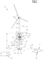
Figure 1 is a schematic perspective view of an assembly according to the invention, -
Figure 2 is a schematic side view of part of a buoyant system shown inFigure 1 ,
and -
Figure 3 is a schematic side view of part of a buoyant system according to a variant of the buoyant system shown inFigures 1 and2 . - An
assembly 10 according to the invention will now be described with reference toFigures 1 and2 . Theassembly 10 is adapted for producing offshore electricity. - The
assembly 10 comprises awind turbine 12, and amonopile 14 extending along a first axis Z intended to be vertical, the monopile being partly immersed in a body of water and for fully supporting the wind turbine. - The
assembly 10 comprises abase 18 resting on aseabed 20, alower end 22 of themonopile 14 and the base being adapted for forming anarticulation 24 allowing the monopile to rotate with respect to the base around a second axis X and a third axis Y perpendicular to each other and to the first axis Z. - The
assembly 10 comprises abuoyant system 26 surrounding themonopile 14 around the vertical direction Z, the buoyant system being intended for floating under asurface 28 of the body ofwater 16, the buoyant system being vertically free with respect to the monopile. - The
assembly 10 for example comprises threeanchoring members 30, and three connectingmembers 32 connected to thebuoyant system 26 on the one hand, and respectively to the anchoringmembers 30 on the other hand, the connecting members being intended to be tensioned by the buoyant system. - As a variant (not shown), the
assembly 10 comprises four or more anchoringmembers 30, and four or more connectingmembers 32. - The
assembly 10 for example comprises astopper 34 fixed to themonopile 14 above thebuoyant system 26, the stopper being adapted for blocking the buoyant system along the first axis Z upwards in case at least one of the connectingmembers 32 breaks. - The body of
water 16 is for example a sea or a lake. The body ofwater 16 is intended to apply an upward force F on thebuoyant system 26. - The
wind turbine 12 comprises atower 34 for example fixed to the top of themonopile 14, andblades 36 rotatably mounted on the tower. - Advantageously, the
tower 34 has a boltedflange 38 which mechanically connects thewind turbine 12 to themonopile 14. - For example, the
monopile 14 has a maximum external diameter D ranging from 8.0 to 12.0 meters, and a height H1 from seabed to top that is greater than 60 meters. - The
monopile 14 advantageously comprises at least 90wt.% of steel or concrete. - The
monopile 14 has alower casing 40 and anupper casing 42 along the first axis Z. - The
lower casing 40 defines a lowerinterior volume 44 containing water. Thelower casing 40 for example extends from thelower end 22 along the first axis Z and advantageously has a frustoconical shape flaring upwards. Alternatively, thelower casing 40 may be done with a trussed beam, with a rectangular or triangular section. - The
upper casing 42 is at least partly immersed in the body ofwater 16. Thesurface 28 of the body of water and theupper casing 42 define an upperinterior volume 46 that is advantageously at least partly devoid of water. Theupper casing 42 advantageously has a cylindrical shape. - The depth of the bottom part of the buoyant part is limited (typically around 50 m for a water depth of 150m) in order to limit the external hydrostatic design pressure.
- The
lower end 22 of themonopile 14 advantageously convex, for example spherical, and is adapted for resting in ahousing 48 defined by the base. This prevents thelower end 22 from shifting along the second axis X and the third axis Y. A pseudo ball joint made with elastomeric pads may also be considered in case frictions between two surfaces in contact was to be avoided. - In the example, the
buoyant system 26 comprisespads 50 adapted for sliding on anexternal surface 52 of theupper casing 42. - As a variant or a complement, the
buoyant system 26 comprises rolls 54 (Figure 3 ) adapted for rolling on theexternal surface 52. - The
buoyant system 26 for example comprises astructure 56 surrounding themonopile 14 around the first axis Z, and threereservoirs 58 fixed to the structure. - As variants (not shown), the
buoyant system 26 comprises only one reservoir advantageously surrounding the monopile 14, or two reservoirs, or more than three reservoirs. Said one reservoir may be cylindrical. - The
buoyant system 26 is for example adapted for applying an upward vertical force F1 on the connectingmembers 32 considered as a whole, said vertical force being larger than x time a limit force (x value being typically in a range from 1.25 to 1.75) , the limit force being such that, when a normalized maximum horizontal effort H is applied to theassembly 10 by wind, current and swell, at least one of the connectingmembers 32 is not tensioned. This advantagesouly provides enough tension in the connectingmembers 32 to give a sufficient safety factor against detensionning. - The
structure 56 for example comprises two circular stiffenedmembers reservoirs 58. - For example, the
rolls 54 comprise rubber and thepads 50 comprise polytetrafluoroethylene or polyamide. Therolls 54 and/orpads 50 are for example fixed to thestructure 56. - The
reservoirs 58 are for example cylindrical around a vertical axis. Thereservoirs 58 advantageously comprise agas 64, for example containing at least 99 vol.% of nitrogen. - Each of the connecting
members 32 advantageously comprises asynthetic rope 66. Steel cables or chains completed by additional buoys to reduce submerged weight may also be considered in the connectingmembers 32. - For example, each of the connecting
members 32 defines an angle α with a horizontal plane P, the angle α being comprised between 15° and 45°. - The connecting
members 32 are advantageously fixed to alower part 68 of thebuoyant system 26, for example to a bottom of each of thereservoirs 58. - Thanks to the above features, the
monopile 14 is guided by thebuoyant system 26, which allows the monopile 14 to simply rest on thebase 18 and limits the required diameter D for themonopile 14. - As a result, the cost of producing and installing the
assembly 10 is reduced, which reduces the offshore electricity cost in some situations where jackets are generally used, because monopiles would be too large to be produced and/or too expensive, or to further reduce the electricity cost in some situation where monopiles can be used. - By keeping the monopile 14 diameter D within reasonable figures, the
assembly 10 also favours a boltedflange 38 between thewind turbine 12 and themonopile 14. - The conical shape of the
lower casing 40 minimizes the amount of material needed to take up a decreasing bending moment. - Thanks to the
articulation 24, and a number of connectingmembers 32 equal to three, theassembly 10 is advantageously isostatic. - The invention also provides design and installation flexibility against water depth and soil conditions variations over large windfarms sites, thus improving serial fabrication and reducing installation costs. The invention allows monopiles to access to larger water depths despite their slenderness. The invention may also improve the design, procurement and installation schedule.
- In general, the invention is adapted to the serial fabrication and installation in windfarm development projects. The invention is also compatible with modern installation vessels, such as Huisman's Windfarms Installation Vessel designed for serial installation of monopiles and wind turbines, reducing logistics and marshalling costs.
- Compared with a pure floating solution, the invention provides lower motions of the support (in a same range to those of a monopile installed in 50m water depth) which facilitate the integration of the turbine with a floating vessel or the future jack-ups operating in large water depth.
Claims (14)
- An assembly (10) for producing offshore electricity comprising:- a wind turbine (12),- a monopile (14) extending along a first axis (Z) intended to be vertical, and adapted for fully supporting the wind turbine (12), the monopile (14) being intended to be partly immersed in a body of water (16), the monopile (14) having lower casing (40) along the first axis (Z) defining a lower interior volume (44) intended to contain water,- a base (18) intended to rest on a seabed (20), a lower end (22) of the monopile (14) and the base (18) being adapted for forming an articulation (24) allowing the monopile (14) to rotate with respect to the base (18) around a second axis (X) and a third axis (Y) perpendicular to each other and to the first axis (Z),- a buoyant system (26) surrounding the monopile (14) around the vertical direction (Z), the buoyant system (26) being intended for floating under a surface (28) of the body of water (16), the buoyant system (26) being vertically free with respect to the monopile (14), the body of water (16) being intended to apply an upward force (F) on the buoyant system (26),- at least three anchoring members (30), and- at least three connecting members (32) connected to the buoyant system (26) on the one hand, and respectively to the anchoring members (30) on the other hand, the connecting members (32) being intended to be tensioned by the buoyant system (26).
- The assembly (10) according to claim 1, wherein the monopile (14) has an upper casing (42) intended to be at least partly immersed in the body of water (16), the upper casing (42) and the surface (28) of the body of water (16) defining an upper interior volume (46) at least partly devoid of water.
- The assembly (10) according to claim 2, wherein the lower casing (40) extends from the lower end (22) along the first axis (Z) and has a frustoconical shape flaring upwards.
- The assembly (10) according to claim 2 or 3, wherein the upper casing (42) has a cylindrical shape, the buoyant system (26) comprises rolls (54) adapted for rolling on an external surface (52) of the upper casing (42), and/or pads (50) adapted for sliding on said external surface (52).
- The assembly (10) according to claim 5, wherein the rolls (54) comprise rubber and the pads (50) comprise polytetrafluoroethylene or polyamide.
- The assembly (10) according to any one of claims 1 to 5, wherein each of the connecting members (32) comprises a synthetic rope (66), steel cable or chain.
- The assembly (10) according to any one of claims 1 to 6, wherein each of the connecting members (32) defines an angle (α) with a horizontal plane (P), the angle (α) being comprised between 15° and 45°.
- The assembly (10) according to any one of claims 1 to 7, wherein the connecting members (32) are fixed to a lower part (68) of the buoyant system (26).
- The assembly (10) according to any one of claims 1 to 8, comprising a stopper (34) fixed to the monopile (14) above the buoyant system (26), the stopper (34) being adapted for blocking the buoyant system (26) along the first axis (Z) upwards in case at least one of the connecting members (32) breaks.
- The assembly (10) according to any one of claims 1 to 9, wherein the buoyant system (26) comprises a structure (56) surrounding the monopile (14) around the first axis (Z), and at least three reservoirs (58) fixed to the structure (56).
- The assembly (10) according to claim 10, wherein the reservoirs (58) comprise a gas (64) containing at least 99 vol.% of nitrogen.
- The assembly (10) according to any one of claims 1 to 11, wherein the buoyant system (26) is adapted for applying an upward vertical force (F1) on the connecting members (32) considered as a whole, said vertical force (F1) being larger than twice a limit force, the limit force being such that, when a normalized maximum horizontal effort (H) is applied to the assembly (10) by wind, current and swell, at least one of the connecting members (32) is not tensioned.
- The assembly (10) according to any one of claims 1 to 12, comprising less than four anchoring members (30), and less than four connecting members (32).
- The assembly (10) according to any one of claims 1 to 13, wherein the monopile (14) has a maximum external diameter (D) ranging from 8.0 to 12.0 meters, and a height (H1) from seabed to top that is greater than 60 meters.
Priority Applications (2)
| Application Number | Priority Date | Filing Date | Title |
|---|---|---|---|
| EP23306007.8A EP4481119A1 (en) | 2023-06-23 | 2023-06-23 | An assembly for producing offshore electricity comprising a wind turbine, a monopile and a tensioning buoyant system freely surrounding the monopile |
| PCT/EP2024/067492 WO2024261273A1 (en) | 2023-06-23 | 2024-06-21 | An assembly for producing offshore electricity comprising a wind turbine, a monopile and a tensioning buoyant system freely surrounding the monopile |
Applications Claiming Priority (1)
| Application Number | Priority Date | Filing Date | Title |
|---|---|---|---|
| EP23306007.8A EP4481119A1 (en) | 2023-06-23 | 2023-06-23 | An assembly for producing offshore electricity comprising a wind turbine, a monopile and a tensioning buoyant system freely surrounding the monopile |
Publications (1)
| Publication Number | Publication Date |
|---|---|
| EP4481119A1 true EP4481119A1 (en) | 2024-12-25 |
Family
ID=87377876
Family Applications (1)
| Application Number | Title | Priority Date | Filing Date |
|---|---|---|---|
| EP23306007.8A Withdrawn EP4481119A1 (en) | 2023-06-23 | 2023-06-23 | An assembly for producing offshore electricity comprising a wind turbine, a monopile and a tensioning buoyant system freely surrounding the monopile |
Country Status (2)
| Country | Link |
|---|---|
| EP (1) | EP4481119A1 (en) |
| WO (1) | WO2024261273A1 (en) |
Citations (4)
| Publication number | Priority date | Publication date | Assignee | Title |
|---|---|---|---|---|
| US3720066A (en) * | 1969-11-20 | 1973-03-13 | Metalliques Entrepr Cie Fse | Installations for submarine work |
| US20120093589A1 (en) * | 2010-10-18 | 2012-04-19 | Peter Broughton | Foundation support system for an offshore wind energy convertor, corresponding to an offshore wind power generating facility |
| WO2021070786A1 (en) * | 2019-10-12 | 2021-04-15 | 株式会社四国Ga | Bottom-mounted offshore platform, offshore wind power generation device, and offshore wind condition observation device |
| CN115467356A (en) * | 2022-10-26 | 2022-12-13 | 袁小荣 | Compliance type offshore wind driven generator foundation structure system |
-
2023
- 2023-06-23 EP EP23306007.8A patent/EP4481119A1/en not_active Withdrawn
-
2024
- 2024-06-21 WO PCT/EP2024/067492 patent/WO2024261273A1/en not_active Ceased
Patent Citations (4)
| Publication number | Priority date | Publication date | Assignee | Title |
|---|---|---|---|---|
| US3720066A (en) * | 1969-11-20 | 1973-03-13 | Metalliques Entrepr Cie Fse | Installations for submarine work |
| US20120093589A1 (en) * | 2010-10-18 | 2012-04-19 | Peter Broughton | Foundation support system for an offshore wind energy convertor, corresponding to an offshore wind power generating facility |
| WO2021070786A1 (en) * | 2019-10-12 | 2021-04-15 | 株式会社四国Ga | Bottom-mounted offshore platform, offshore wind power generation device, and offshore wind condition observation device |
| CN115467356A (en) * | 2022-10-26 | 2022-12-13 | 袁小荣 | Compliance type offshore wind driven generator foundation structure system |
Also Published As
| Publication number | Publication date |
|---|---|
| WO2024261273A1 (en) | 2024-12-26 |
Similar Documents
| Publication | Publication Date | Title |
|---|---|---|
| US7819073B2 (en) | Floating wind turbine installation | |
| US9446822B2 (en) | Floating wind turbine platform with ballast control and water entrapment plate systems | |
| JP5143825B2 (en) | Improved wave energy converter (WEC) with heave plate | |
| EP4636245A2 (en) | Shallow draft, wide-base floating wind turbine without nacelle | |
| US20120093589A1 (en) | Foundation support system for an offshore wind energy convertor, corresponding to an offshore wind power generating facility | |
| JP2024505494A (en) | wind power plant | |
| JP6155326B2 (en) | Wind turbine on a floating support stabilized by a raised anchoring system | |
| NO347179B1 (en) | A mooring system for a plurality of floating units | |
| US20240083552A1 (en) | Mooring system | |
| GB2542548A (en) | System and method | |
| US12460620B2 (en) | Floating windmill | |
| WO2024261273A1 (en) | An assembly for producing offshore electricity comprising a wind turbine, a monopile and a tensioning buoyant system freely surrounding the monopile | |
| KR20240017162A (en) | Submersible assembly for supporting offshore wind turbines mounted on monopiles | |
| KR102753932B1 (en) | Floating anchor structure for photovoltaic system and wind system | |
| KR20220103530A (en) | Offshore wind generator with floating support structure | |
| EP4570639A1 (en) | An assembly for producing offshore electricity comprising a double anchored floating support | |
| WO2026042417A1 (en) | Taut-moored floating structure | |
| KR20250160349A (en) | Floating platform with vertically arranged mooring system | |
| WO2021124361A1 (en) | Marine system for the generation of electric energy from the pitch of floating bodies induced by wave motion |
Legal Events
| Date | Code | Title | Description |
|---|---|---|---|
| PUAI | Public reference made under article 153(3) epc to a published international application that has entered the european phase |
Free format text: ORIGINAL CODE: 0009012 |
|
| STAA | Information on the status of an ep patent application or granted ep patent |
Free format text: STATUS: THE APPLICATION HAS BEEN PUBLISHED |
|
| AK | Designated contracting states |
Kind code of ref document: A1 Designated state(s): AL AT BE BG CH CY CZ DE DK EE ES FI FR GB GR HR HU IE IS IT LI LT LU LV MC ME MK MT NL NO PL PT RO RS SE SI SK SM TR |
|
| STAA | Information on the status of an ep patent application or granted ep patent |
Free format text: STATUS: THE APPLICATION IS DEEMED TO BE WITHDRAWN |
|
| 18D | Application deemed to be withdrawn |
Effective date: 20250626 |