EP4481103A1 - Clothing processing apparatus - Google Patents
Clothing processing apparatus Download PDFInfo
- Publication number
- EP4481103A1 EP4481103A1 EP23756614.6A EP23756614A EP4481103A1 EP 4481103 A1 EP4481103 A1 EP 4481103A1 EP 23756614 A EP23756614 A EP 23756614A EP 4481103 A1 EP4481103 A1 EP 4481103A1
- Authority
- EP
- European Patent Office
- Prior art keywords
- filter
- mounting portion
- treatment apparatus
- laundry treatment
- outer filter
- Prior art date
- Legal status (The legal status is an assumption and is not a legal conclusion. Google has not performed a legal analysis and makes no representation as to the accuracy of the status listed.)
- Pending
Links
Images







Classifications
-
- D—TEXTILES; PAPER
- D06—TREATMENT OF TEXTILES OR THE LIKE; LAUNDERING; FLEXIBLE MATERIALS NOT OTHERWISE PROVIDED FOR
- D06F—LAUNDERING, DRYING, IRONING, PRESSING OR FOLDING TEXTILE ARTICLES
- D06F58/00—Domestic laundry dryers
- D06F58/20—General details of domestic laundry dryers
- D06F58/22—Lint collecting arrangements
-
- D—TEXTILES; PAPER
- D06—TREATMENT OF TEXTILES OR THE LIKE; LAUNDERING; FLEXIBLE MATERIALS NOT OTHERWISE PROVIDED FOR
- D06F—LAUNDERING, DRYING, IRONING, PRESSING OR FOLDING TEXTILE ARTICLES
- D06F58/00—Domestic laundry dryers
- D06F58/02—Domestic laundry dryers having dryer drums rotating about a horizontal axis
- D06F58/04—Details
- D06F58/08—Driving arrangements
-
- D—TEXTILES; PAPER
- D06—TREATMENT OF TEXTILES OR THE LIKE; LAUNDERING; FLEXIBLE MATERIALS NOT OTHERWISE PROVIDED FOR
- D06F—LAUNDERING, DRYING, IRONING, PRESSING OR FOLDING TEXTILE ARTICLES
- D06F58/00—Domestic laundry dryers
- D06F58/20—General details of domestic laundry dryers
- D06F58/206—Heat pump arrangements
-
- D—TEXTILES; PAPER
- D06—TREATMENT OF TEXTILES OR THE LIKE; LAUNDERING; FLEXIBLE MATERIALS NOT OTHERWISE PROVIDED FOR
- D06F—LAUNDERING, DRYING, IRONING, PRESSING OR FOLDING TEXTILE ARTICLES
- D06F58/00—Domestic laundry dryers
- D06F58/20—General details of domestic laundry dryers
- D06F58/24—Condensing arrangements
-
- D—TEXTILES; PAPER
- D06—TREATMENT OF TEXTILES OR THE LIKE; LAUNDERING; FLEXIBLE MATERIALS NOT OTHERWISE PROVIDED FOR
- D06F—LAUNDERING, DRYING, IRONING, PRESSING OR FOLDING TEXTILE ARTICLES
- D06F58/00—Domestic laundry dryers
- D06F58/20—General details of domestic laundry dryers
- D06F58/26—Heating arrangements, e.g. gas heating equipment
- D06F58/263—Gas heating equipment
-
- D—TEXTILES; PAPER
- D06—TREATMENT OF TEXTILES OR THE LIKE; LAUNDERING; FLEXIBLE MATERIALS NOT OTHERWISE PROVIDED FOR
- D06F—LAUNDERING, DRYING, IRONING, PRESSING OR FOLDING TEXTILE ARTICLES
- D06F58/00—Domestic laundry dryers
- D06F58/32—Control of operations performed in domestic laundry dryers
- D06F58/34—Control of operations performed in domestic laundry dryers characterised by the purpose or target of the control
-
- D—TEXTILES; PAPER
- D06—TREATMENT OF TEXTILES OR THE LIKE; LAUNDERING; FLEXIBLE MATERIALS NOT OTHERWISE PROVIDED FOR
- D06F—LAUNDERING, DRYING, IRONING, PRESSING OR FOLDING TEXTILE ARTICLES
- D06F2103/00—Parameters monitored or detected for the control of domestic laundry washing machines, washer-dryers or laundry dryers
- D06F2103/02—Characteristics of laundry or load
- D06F2103/08—Humidity
-
- D—TEXTILES; PAPER
- D06—TREATMENT OF TEXTILES OR THE LIKE; LAUNDERING; FLEXIBLE MATERIALS NOT OTHERWISE PROVIDED FOR
- D06F—LAUNDERING, DRYING, IRONING, PRESSING OR FOLDING TEXTILE ARTICLES
- D06F2103/00—Parameters monitored or detected for the control of domestic laundry washing machines, washer-dryers or laundry dryers
- D06F2103/28—Air properties
- D06F2103/34—Humidity
-
- D—TEXTILES; PAPER
- D06—TREATMENT OF TEXTILES OR THE LIKE; LAUNDERING; FLEXIBLE MATERIALS NOT OTHERWISE PROVIDED FOR
- D06F—LAUNDERING, DRYING, IRONING, PRESSING OR FOLDING TEXTILE ARTICLES
- D06F2103/00—Parameters monitored or detected for the control of domestic laundry washing machines, washer-dryers or laundry dryers
- D06F2103/42—Parameters monitored or detected for the control of domestic laundry washing machines, washer-dryers or laundry dryers related to filters or pumps
-
- D—TEXTILES; PAPER
- D06—TREATMENT OF TEXTILES OR THE LIKE; LAUNDERING; FLEXIBLE MATERIALS NOT OTHERWISE PROVIDED FOR
- D06F—LAUNDERING, DRYING, IRONING, PRESSING OR FOLDING TEXTILE ARTICLES
- D06F2105/00—Systems or parameters controlled or affected by the control systems of washing machines, washer-dryers or laundry dryers
- D06F2105/56—Remaining operation time; Remaining operational cycles
-
- D—TEXTILES; PAPER
- D06—TREATMENT OF TEXTILES OR THE LIKE; LAUNDERING; FLEXIBLE MATERIALS NOT OTHERWISE PROVIDED FOR
- D06F—LAUNDERING, DRYING, IRONING, PRESSING OR FOLDING TEXTILE ARTICLES
- D06F2105/00—Systems or parameters controlled or affected by the control systems of washing machines, washer-dryers or laundry dryers
- D06F2105/62—Stopping or disabling machine operation
-
- D—TEXTILES; PAPER
- D06—TREATMENT OF TEXTILES OR THE LIKE; LAUNDERING; FLEXIBLE MATERIALS NOT OTHERWISE PROVIDED FOR
- D06F—LAUNDERING, DRYING, IRONING, PRESSING OR FOLDING TEXTILE ARTICLES
- D06F34/00—Details of control systems for washing machines, washer-dryers or laundry dryers
- D06F34/14—Arrangements for detecting or measuring specific parameters
-
- D—TEXTILES; PAPER
- D06—TREATMENT OF TEXTILES OR THE LIKE; LAUNDERING; FLEXIBLE MATERIALS NOT OTHERWISE PROVIDED FOR
- D06F—LAUNDERING, DRYING, IRONING, PRESSING OR FOLDING TEXTILE ARTICLES
- D06F58/00—Domestic laundry dryers
- D06F58/20—General details of domestic laundry dryers
Definitions
- the present disclosure relates to a clothing processing apparatus , and more particularly to a clothing processing apparatus including a filter cartridge configured to remove foreign substances from air.
- the conventional clothing processing apparatus designed to perform a drying procedure capable of removing moisture from laundry has been suggested.
- the conventional clothing processing apparatus is configured to supply hot air to a drum receiving laundry therein to dry the laundry, thereby not only remarkably reducing time required to dry the laundry but also performing disinfection and sterilization of the laundry.
- the conventional clothing processing apparatus may use an electrical heater in order to supply hot air to the drum. Accordingly, it is possible to create hot air by installing a heater at a duct communicating with the drum to heat the air introduced into the drum.
- the clothing processing apparatus designed to heat air introduced into a drum using a heat pump system has been suggested.
- the clothing processing apparatus is able to create dry and hot air by cooling air discharged from laundry to condense moisture using an evaporator and by heating the air again using a condenser.
- the clothing processing apparatus equipped with the heat pump system has advantages of having higher energy efficiency than a clothing processing apparatus equipped with an electrical heater, of being simplified in installation, and of being easier to repair and replace.
- the conventional clothing processing apparatus develops a problem in that air discharged from laundry directly collides with an evaporator and thus foreign substances such as lint adhere to the evaporator. Accordingly, there is a problem in that the foreign substances adhering to the evaporator hinder heat exchange between cool refrigerant flowing through the evaporator and the air discharged from the drum, thereby deteriorating drying efficiency.
- the clothing processing apparatus is provided with a filter portion detachably mounted thereon, thereby filtering foreign substances and enabling a user to separate the filter portion and remove foreign substances collected in the filter portion.
- the filter portion may be embodied as double filters configured to filter foreign substances having different sizes in order to improve foreign substance removal ability.
- the double filters are able to filter lint or dust having different sizes.
- the inner filter In the case of double type filter portion, the inner filter should be mounted after the outer filter is mounted.
- the conventional clothing processing apparatus has the high possibility that the clothing processing apparatus is used in the state of only the outer filter or the inner filter being mounted due to user's carelessness.
- the outer filter is mounted on the mounting portion, which is formed at the introduction port so as to have a stepped shape, so as not be exposed to the outside, there are many cases in which a user uses the clothing processing apparatus in the state in which only the inner filter is mounted on the mounting portion.
- the clothing processing apparatus is constructed such that a magnet is installed at the filter portion and a sensor such as a Hall sensor configured to sense the magnet is installed at the mounting portion. Accordingly, the clothing processing apparatus can be operated only when the sensor senses the magnet of the filter portion, thereby inducing a user to couple the filter portion to the mounting portion.
- the clothing processing apparatus is constructed such that the inner filter and the outer filter are respectively provided with magnets and the sensor must sense all of the two magnets or the state of the two magnets overlapping each other, there is a problem in that it is difficult to exactly determine whether the inner filter and the outer filter are mounted.
- the conventional clothing processing apparatus also proposes a configuration in which a cantilever-type magnet is provided in the outer filter and the inner filter pushes out the cantilever-type magnet such that the sensor determines mounting of the two filters by sensing only the one magnet.
- the conventional clothing processing apparatus determines whether both the inner filter and the outer filter are mounted, not in a physical manner but in an electronic control manner using the sensor and the magnet, there is a problem in that it is impossible to assure reliability.
- An object to be solved according to the present disclosure is to provide a clothing processing apparatus capable of determining whether both an outer filter and an inner filter are coupled, in a physical manner.
- An object to be solved according to the present disclosure is to provide a clothing processing apparatus which enables a user to determine whether the outer filter or the inner filter is not coupled, in a physical manner.
- An object to be solved according to the present disclosure is to provide a clothing processing apparatus which makes it impossible for the outer filter or the inner filter alone to be mounted.
- the present disclosure provides a clothing processing apparatus including a double type filter portion.
- the double type filter portion may be constructed such that one of the two filters cannot be completely mounted until the other of the two filters is mounted. In other words, in order to complete mounting of all of the filters, all of the filters should be disposed.
- the clothing processing apparatus may include a signal generator coupled to the filter portion so as to generate an external signal, a sensor provided at the mounting portion so as to sense the signal generator, and a controller configured to permit operation of at least one of the heat supply portion or the driving portion when the sensor senses the signal generator, and the signal generator may be installed at the outer filter.
- the elastic portion may be configured to cause the seating body to be taken out of the mounting portion, thereby preventing the door from closing the opening.
- the seating body may be capable of projecting to an inside of the introduction port by means of the elastic portion.
- the seating body may include a seating portion which extends outwards from the insertion body and is seated on an upper surface of the mounting portion, and the elastic portion may be coupled to a lower surface of the seating portion so as to come into contact with the upper surface of the mounting portion.
- the mounting portion may include a mounting groove which is formed through an inner circumferential surface of the introduction port and by which the filter portion is supported, and a mounting body which extends to the circulation duct from the mounting groove and which receive the filter portion, the sensor being installed on an outer circumferential surface of the mounting body, and the coupler may include a coupling hook which projects from a lateral surface of the support body and is detachably coupled to an inner surface of the mounting groove.
- Each of the plurality of coupling ribs may include a push portion to which the elastic member is coupled, and an extension rib which extends toward a corresponding one of the two lateral surfaces of the support body and the distal end of which is provided with the coupling hook, and the support body may include a guide case which receives the elastic member at an upper surface thereof and which exposes the push portions through two lateral sides thereof.
- the plurality of coupling ribs may be spaced apart from each other by a distance corresponding to a distance the coupling hooks in the guide case are separated from the mounting groove.
- the support body may include movement rails which extend in a width direction thereof and guide the plurality of coupling ribs.
- the sensor may be disposed at a position corresponding to the signal generator when the coupler fixes the support body to the mounting portion.
- one of the outer filter and the inner filter may be completely mounted on the mounting portion when the other of the outer filter and the inner filter is mounted on the mounting portion.
- the inner filter may be shakable and thus not be fixed when the inner filter alone is mounted on the mounting portion.
- the inner filter may include a support body seated on an upper surface of the outer filter, and a reception body which extends from the support body and at least a portion of which is inserted into the outer filter or the mounting portion, and the support body may be shakable on an upper surface of the mounting portion when the support body is mounted on the mounting portion.
- the outer filter may receive the inner filter therein and fix the inner filter.
- the outer filter may include a seating body seated on the mounting portion without shaking, and an insertion body which extends from the seating body and is seated on the mounting portion and which receives the reception body, and at least a portion of an inner surface of the insertion body may contact and support an outer surface of the reception body.
- the outer filter may be removeable from the mounting portion when the inner filter is not mounted on the mounting portion.
- the inner filter may be fixed to the mounting portion in a state of pressing the outer filter.
- the clothing processing apparatus may be constructed such that the signal generator is reciprocatedalong one surface of one of the mounting portion, the outer filter and the inner filter.
- the signal generator may be moved toward the sensor when the outer filter or the inner filter is seated on the mounting portion.
- the signal generator may be provided on an inner circumferential surface of the mounting portion, and may be moved in an up-and-down direction toward the sensor by the outer filter.
- the signal generator may be provided on an inner surface of the outer filter so as to be moved downwards by the inner filter.
- the inner filter may include an upper protrusion which projects from an outer surface thereof and which pushes the signal generator downwards.
- the signal generator may be provided on an outer surface of the inner filter so as to be moved upwards by the outer filter.
- the outer filter may include a lower protrusion which projects from an inner surface thereof and which pushes the signal generator upwards.
- the signal generator may include a magnet interacting with the sensor, a guide rail installed at an inner surface of the mounting portion, the outer filter, and the inner filter, and a restoring portion installed at the guide rail so as to push the magnet upwards or downwards.
- the present disclosure has an effect of being capable of accurately sensing or determining whether both the outer filter and the inner filter are mounted.
- the present disclosure has an effect of being capable of determining whether both the outer filter and the inner filter are coupled, in a physical manner.
- the present disclosure has an effect of being capable of determining whether the outer filter or the inner filter is not coupled, in a physical manner.
- the present disclosure has an effect of inducing a user to mount both the outer filter and the inner filter.
- the present disclosure has an effect of assuring reliability and durability even when movement of the magnet and the sensor configured to sense the movement are utilized.
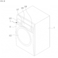
- FIG. 2 illustrates the appearance of the clothing processing apparatus according to the embodiment of the present disclosure.
- the clothing processing apparatus includes a cabinet 1, a drum 2 which is rotatably provided in the cabinet and provides a space configured to store laundry therein, a circulation duct 3 defining a flow channel configured to supply the air, discharged from the drum 2, back to the drum 2, and a heat exchanger portion 4 configured to dehumidify and heat the air into the circulation duct 3 and to supply the dehumidified air to the drum 2.
- the cabinet 1 may include a front panel 11 defining the front surface of the clothing processing apparatus .
- the front panel 11 may be provided with an opening 111 communicating with the drum 2 and a door 112 rotatably coupled to the cabinet so as to open and close the opening 111.
- the front panel 11 may be provided with a control panel 117.
- the control panel 117 may be provided with an input portion 118, through which control commands are input from a user, and a display portion 119 to which information, such as control commands which are selectable by the user, is output.
- the control panel 117 may further include a controller or may be connected to the controller.
- the controller may control the input portion 118 and the display portion 119 or may control all electronic components such as a driving portion, the heat exchanger portion, a washer 6 and a sensor 400 which will be described later.
- the controller may generate a command for activating the clothing processing apparatus .
- the controller may control at least one of the driving portion or the heat exchanger portion to enable the clothing processing apparatus to perform a drying procedure configured to remove moisture from the laundry.
- the input portion 118 may include a power supply request portion configured to request supply of power, a course input portion configured to enable a user to select a desired course among a plurality of courses, and an execution request portion configured to request initiation of the course selected by the user.
- a command for operating the clothing processing apparatus may be input through the input portion 118, and may be transmitted to the controller.
- the controller may control various electronic components of the clothing processing apparatus in response to the command.
- the display portion 119 may include one of a display panel capable of outputting text and graphics and a speaker capable of outputting voice signals and sound.
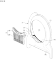
- FIG. 3 illustrates the internal structure of the clothing processing apparatus according to the present disclosure.
- the clothing processing apparatus 100 includes a cabinet 1, a drum 2 which is rotatably provided in the cabinet and provides a space configured to store laundry therein, a circulation duct 3 defining a flow channel configured to supply the air, discharged from the drum 2, back to the drum 2, and a heat exchanger portion 4 configured to dehumidify and heat the air into the circulation duct 3 and to supply the dehumidified air to the drum 2.
- the cabinet 1 may be provided therein with a first support 17 configured to rotatably support the front surface of the drum 2 and a second support 19 configured to rotatably support the rear surface of the drum 2.
- the first support 17 may include a first fixed body 171 which is fixed in the cabinet 1, and an introduction port 173 which is formed through the first fixed body so as to allow the opening 111 to communicate with the inside of the drum body 21.
- the first support 17 may further include a first support body 175 which is provided at the first fixed body 171 and is inserted into the front side of the drum body 21.
- the first fixed body 171 may be formed to have any shape as long as it includes the introduction port 173 and the first support body 175.
- the first support body 175 may be formed to have the form of a pipe which projects toward the drum body 21 from the first fixed body 171.
- the diameter of the first support body 175 may be set to be larger than the diameter of the introduction port 173 but smaller than the diameter of the front surface of the drum body 21.
- the introduction port 173 may be positioned in the space defined by the first support body 175.
- the first support 17 may further include a connecting body 177 connecting the opening 111 to the introduction port 173.
- the connecting body 177 may be formed to have the form of a pipe which extends toward the opening 111 from the introduction port 173.
- the connecting body 177 may be provided with a mounting portion 178 communicating with the circulation duct 3.
- the mounting portion 178 may be a passage which allows the air in the drum body 21 to flow to the circulation duct 3, and may be formed through the connecting body 177.
- the mounting portion 178 may be constructed so as to allow the introduction port 173 to communicate with the circulation duct 3, and may be formed to have the form of a duct which is depressed at one end thereof from the introduction port 173.
- the mounting portion 178 may be constructed so as to allow the air to be introduced thereinto from the drum 2. The introduced air may flow to the circulation duct 3 through the mounting portion 178.
- the second support 19 may include a second fixed body 191 fixed in the cabinet 1, and a second support body 195 which is provided at the second fixed body 191 and is inserted into the rear surface (a second open surface) of the drum body 21.
- the second support 19 may be provided with an air inflow hole 198 which is formed through the second fixed body 191 so as to allow the inside of the drum body 21 to communicate with the inside of the cabinet 1.
- the circulation duct 3 may connect the mounting portion 178 to the air inflow hole 198.
- FIG. 3 illustrates an example in which the driving portion 28 includes a motor 23 fixed in the cabinet 1, a pulley 25 which is rotatable by means of the motor, and a belt 27 connecting the circumferential surface of the pulley 25 to the circumferential surface of the drum body 21.
- the first support 17 may be provided with a first roller 179 configured to rotatably support the circumferential surface of the drum body 21, and the second support 19 may be provided with a second roller 199 configured to rotatably support the circumferential surface of the drum body.
- the circulation duct 3 may include an exhaust duct 31 connected to the mounting portion 178, a supply duct 33 connected the air inflow hole 198, and a connecting duct 35 connecting the exhaust duct to the supply duct.
- the heat exchanger portion 4 may be embodied as any of various devices capable of sequentially performing dehumidification and heating of the air introduced into the circulation duct 3.
- the heat exchanger portion 4 may be embodied as a heat pump system.
- the heat exchanger portion 4 may include a fan 49 configured to move air through the circulation duct 3, a first heat exchanger (a heat adsorber) 41 configured to remove moisture from the air introduced into the circulation duct 3, and a second heat exchanger (a heat radiator) 43 which is provided in the circulation duct 3 so as to heat the air having passed through the first heat exchanger 41.
- a fan 49 configured to move air through the circulation duct 3
- a first heat exchanger (a heat adsorber) 41 configured to remove moisture from the air introduced into the circulation duct 3
- a second heat exchanger (a heat radiator) 43 which is provided in the circulation duct 3 so as to heat the air having passed through the first heat exchanger 41.
- the fan 49 may include an impeller 491 provided in the circulation duct 3 and an impeller motor 493 configured to rotate the impeller 491 (see FIG. 4 ).
- the impeller 491 may be provided at any of the exhaust duct 31, the connecting duct 35 and the supply duct 33.
- FIG. 3 illustrates an example in which the impeller 491 is provided at the supply duct 33 (an example in which the impeller 491 is positioned behind the heat radiator).
- the evaporator 41 may be composed of a plurality of metal plates which are arranged in the width direction (the Y-axis direction) or the height direction (the Z-axis direction) of the connecting duct 35, and the condenser 43 may be composed of a plurality of metal plates which are arranged in the width direction or the height direction of the connecting duct.
- the evaporator 41 and the condenser 43 may be sequentially arranged in a direction of the supply duct 33 from the exhaust duct 31 in the connecting duct 35, and may be connected to each other via a refrigerant pipe 48 defining a circulation channel for refrigerant.
- the refrigerant may be moved along the refrigerant pipe 48 by means of a compressor 45 positioned outside the circulation duct 3.
- the refrigerant pipe 48 may be provided with a pressure regulator 47 configured to regulate the pressure of the refrigerant having passed through the condenser 43.
- the evaporator 41 is a device configured to transmit the heat of the air introduced into the exhaust duct 31 to the refrigerant to cool the air while evaporating the refrigerant.
- the condenser 43 is a device configured to transmit the heat of the refrigerant having passed through the compressor 45 to the air to heat the air while condensing the refrigerant.
- the moisture contained in the air may be collected on the bottom surface of the connecting duct 35 along the surface of the evaporator 41 while passing through the evaporator 41.
- the clothing processing apparatus 100 may be provided with a water collector.
- the water collected in the water collector may be collected in a reservoir 7 so as to be discharged at a time later.
- the reservoir 7 may include a storage body 72 which is detachably provided at the cabinet 1 so as to provide a space configured to store water therein, and an inflow hole 722 which is formed through the storage body 72 so as to allow the water discharged from a reservoir supply pipe 633 to be introduced into the storage body 72.
- the storage body 72 may be embodied as a drawer-type tank which is drawn out of the cabinet 1.
- the front panel 11 of the cabinet must be provided with a reservoir mounting groove into which the storage body 72 is inserted.
- a panel 71 may be fixed to the front surface of the storage body 72.
- the panel 71 may be detachably coupled to the reservoir mounting groove so as to form a portion of the front panel 11.
- the panel 71 may further be provided with a groove 711 into which a user hand is inserted.
- the panel 71 may also serve as a handle which enables the storage body 72 to be drawn out of or inserted into the cabinet.
- the inflow hole 722 may be configured to receive the water discharged from a nozzle 722a fixed to the cabinet 1.
- the nozzle 722a may be fixed to an upper panel 13 of the cabinet such that the nozzle 722a is positioned above the inflow hole 722 when the storage body 72 is inserted into the cabinet 1.
- the reservoir 7, which has the above-mentioned configuration, may be constructed such that the water contained in the storage body 72 can be discarded by drawing the storage body 72 out of the cabinet 1 and then turning or tilting the storage body 72 such that the inflow hole 722 is positioned at a lower level.
- the storage body 72 may further include a communication hole 721 formed through the upper surface of the storage body 72.
- the heat exchanger portion 4 may be configured to condense the moisture in the air circulated in the evaporator 41. Accordingly, because the moisture is removed in the evaporator 41 even when the air is circulated in the drum 2, it is possible to continually dry the laundry in the drum 2.
- the moisture condensed in the evaporator 41 may be first collected in the water collector 37 and then be secondly collected in the reservoir 7.
- the water collector 37 may be positioned in the connecting duct 35, and may be separately provided in a space isolated from the connecting duct 35.
- the clothing processing apparatus 100 may further include at least one of a filter portion or a second filter portion which filter the air.
- the filter portion 10 may be embodied as a device configured to filter the air introduced into the exhaust duct 31 from the drum body 21, and the second filter portion 5 may be embodied as a device which is positioned between the filter portion 10 and the evaporator 41 so as to filter the air having passed through a second filter.
- the diameter of filtering holes formed in the filter portion 5 may be set to be smaller than the diameter of filtering holes formed in the filter portion 10.
- the filter portion 10 may be detachably inserted into the exhaust duct 31 through the mounting portion 178.
- the second filter portion 5 may be detachably provided at the connecting duct 35.
- the front panel 11 of the cabinet may be provided with a drawing hole 113 (see FIG. 3 ) through which the second filter portion 5 is drawn out, and a drawing hole door 114 configured to open and close the drawing hole, and the circulation duct 3 may be provided with a duct through hole through which the second filter portion 5 is inserted. Accordingly, a user can separate the second filter portion 5 from the clothing processing apparatus and then can remove foreign substances remaining in the second filter portion 5 and wash a first filter.
- the second filter portion 5 may include second filter portion bodies 51, 53, 57 and 58 which are inserted into the drawing hole 113 and the duct through hole 34 and are positioned between the filter portion 10 and the evaporator 41, and second filter portion members 531, 551 and 571 which are provided at the second filter portion bodies so as to filter fluid (air and water) which flows to the evaporator 41 and a water collector body 371.
- Each of the second filter portion bodies may have various forms depending on the shape of the connecting duct 35 in cross-section (Y-Z plane and X-Z plane)
- the second filter portion body may include a front surface 51 which is constructed so as to close the duct through hole 34, a rear surface 53 positioned between the front surface and the evaporator 41, a bottom surface connecting the front surface to the rear surface, and a first lateral surface 57 and a second lateral surface 58 which define left and right surfaces of the second filter portion body.
- the front surface 51 may be provided with a lock 513 which is detachably coupled to a lock fastener 16 provided at the cabinet.
- the lock 513 may be embodied as a bar which is rotatably coupled to the front surface 51 of the second filter portion body, and the lock fastener 16 may be formed to have a groove in which the free end of the bar is received.
- the lock 513 is preferably composed of a pair of locks which are provided at two opposite sides of the front surface 51, and the lock fastener 16 is preferably composed of a pair of lock fasteners which are provided at two opposite sides of the filter mounting groove 113.
- the front surface 51 may further be provided with a handle 511.
- the rear surface 53 and the bottom surface 55 may be respectively provided with a first filter member 531 and a second filter member 551 which filter the fluid (air and water) introduced into the second filter portion body.
- the rear surface 53 may be provided with a rear surface through hole which allows the inside of the second filter portion body to communicate with the internal space in the circulation duct 3.
- the first filter member 531 may be provided in the rear surface through hole.
- the bottom surface 55 may be provided with a bottom surface through hole which allows the inside of the second filter portion body to communicate with the internal space in the circulation duct 3.
- the second filter member 551 may be provided in the bottom surface through hole. Consequently, the first filter member 531 may be a device configured to filter the fluid (air and water) supplied to the evaporator 41, and the second filter member 551 may be a device configured to filter the fluid supplied to the water collector body 371
- the first lateral surface 57 and the second lateral surface 58 may connect the front surface 51, the rear surface 53 and the bottom surface 55 to one another.
- the second filter portion 5 which is constructed as described above, may communicate with the exhaust duct 31 through the upper surface of the second filter portion body or the second lateral surface 58.
- the second filter portion 5 may be connected to the exhaust duct 31 through an upper surface through hole formed through the upper surface of the second filter portion body and a lateral surface through hole formed through the second lateral surface 58.
- the first filter member 531 may be inclined to an angle ranging from 90 to 100 degrees toward the front surface of the evaporator based on the bottom surface 55 of the second filter portion body. The reason for this is to allow foreign substances remaining in the first filter member to easily move to the bottom surface 55 when water is sprayed to the first filter member 531 through a moving portion 6 which will be described later.
- the second filter member 551 may be inclined downwards at an angle ranging from 10 to 20 degrees towards the first filter member 531 from the front surface 51 (the second filter member may be inclined upwards by an angle ranging from 10 to 20 degrees toward the drawing hole from the lower end of the first filter member).
- the connecting point between the first filter member 531 and the second filter member 551 becomes the lowermost point in the space defined by the first filter member, with the result that foreign substances in the second filter portion 5 may concentrate on the connecting point between the first filter member 531 and the second filter member 551.
- a user can more easily remove the foreign substances in the second filter portion 5.
- the first lateral surface 57 may further be provided with a bypass hole, which allows the inside of the second filter portion 5 to communicate with water collector body 371, and a third filter member 571 provided at the bypass hole.
- the bypass hole and the third filter member 571 may be positioned higher than the highest end of the second filter member 551 but lower than the lowest end of the first filter member 531. Consequently, the clothing processing apparatus is able to minimize a phenomenon in which the water sprayed to the second filter portion 5 is not collected to the water collector body 371 due to the foreign substances remaining in the second filter portion 5.
- the clothing processing apparatus 100 may include the moving portion 6 configured to utilize the water stored in the water collector body 371, and a discharger 900 which is coupled to the moving portion 6 so as to receive the water to wash the evaporator 41 of the first filter 5.
- the water stored in the water collector body 371 may be separately collected in the reservoir 7, and may be selectively moved to the moving portion 6.
- the moving portion 6 may be embodied as a device configured to spray the water stored in the water collector body 371 to wash at least one of the second filter portion 5 or the evaporator 41.
- the moving portion 6 may be provided at the circulation duct 3 so as to supply water the discharger 900 configured to supply water to the second filter portion 5 or the evaporator 41.
- the moving portion 6 may include a wash pump 61 configured to move the water stored in the water collector body 371 to the discharger 900.
- the reservoir supply pipe 633 should be configured to connect the nozzle 722a to the channel converter 63.
- the channel converter 63 may include a valve configured to control opening and closing of the sprayer supply pipe 631 and the reservoir supply pipe 633. Accordingly, because the clothing processing apparatus 100 includes the valve provided at the channel converter 63, it is possible to supply the water stored in the water collector body 371 to the discharger 65 or the reservoir 7.
- the sprayer supply pipe 631 may be coupled to the connecting duct 35, specifically to one surface of the connecting duct 35 corresponding to the upper surface of the evaporator 41. Consequently, the water supplied to the sprayer supply pipe 631 may be discharged to the evaporator 41 of the first filter 5, thereby removing foreign substances from the evaporator 41 or the second filter portion 5.
- the moving portion 6 may receive not only the water condensed in the evaporator 41 but also fresh water from a water supply 300.
- a pipe directly connecting the water supply 300 to the moving portion 6 may be provided.
- the clothing processing apparatus 100 may include a dryness sensor to determine dryness of laundry and thus to determine the halting time of operation of the heat exchanger portion 4.
- the dryness sensor may be embodied as at least one of an electrode sensor, which comes into contact with laundry to measure an amount of moisture contained in laundry, or a humidity sensor configured to measure humidity of the air introduced into the circulation duct 3 from the drum 2.
- the clothing processing apparatus 100 is able to determine dryness of laundry by observing electrical resistance measured when the electrode sensor is connected to the laundry. Because an amount of moisture contained in the air introduced into the circulation duct 3 decreases as dryness of laundry increases, the clothing processing apparatus 100 is able to determine dryness of the laundry by observing humidity of the air introduced into the circulation duct 3 via the humidity sensor
- the drum body 21 may further include a drum rear surface which is coupled to the rear surface of the drum body so as to close the rear surface, and the driving portion may be coupled to the drum rear surface so as to directly rotate the drum body 21.
- the driving portion may be coupled to the second support 19 and be supported thereby.
- the driving portion includes the motor 23 fixed in the cabinet 1, the pulley 25 rotated by the motor, and the belt 27 connecting the circumferential surface of the pulley 25 to the circumferential surface of the drum body 21.
- the first support 17 may include a first roller 179 configured to rotatably support the circumferential surface of the drum body 21, and the second support 19 may include a second roller 199 configured to rotatably support the circumferential surface of the drum body.
- the heat exchanger support 128, which supports the heat absorber 41 and the heat radiator 43, may be provided with a plurality of support plate through holes (not shown) which are formed so as to correspond to the position of the heat absorber.
- the support plate through holes may guide the water generated in the heat absorber 41 and/or the water used to wash the heat absorber 41 to the water collecting chamber 127.
- the laundry dryer 100 may further include a washer 6 configured to wash the heat absorber 41 using the water stored in the water collecting chamber 127, and a water discharger 7 configured to discharge the water in the water collecting chamber 127 to the outside.
- the washer 6 may be embodied as a device configured to spray the water contained in the water collecting chamber 127 to the heat absorber 41.
- the washer 6 may include the sprayer 65 which is provided at the circulation duct 3 so as to supply water the heat absorber 41, and the pump 61 configured to move the water stored in the water collecting chamber 127 to the sprayer 65.
- the pump 61 may supply the water discharged from the water collecting chamber 127 to the sprayer 65 through the second connecting pipe 613.
- the pump 61 may be positioned adjacent to the water collecting chamber 127 so as to move the water in the water collecting chamber 127, or may be connected to the water collecting chamber via the first connecting pipe 611.
- the clothing processing apparatus 100 may further include the channel converter 63.
- the channel converter 63 may be connected to the pump 61 via the second connecting pipe 613
- the sprayer 65 may be connected to the channel converter 63 via the sprayer supply pipe 631
- the water discharger 7 may be connected to the channel converter 63 via the water discharger supply pipe 633.
- the channel converter 63 may include the valve (not shown) configured to control opening and closing of the sprayer supply pipe 631 and the water discharger supply pipe 633. Accordingly, the laundry dryer 100 may control the valve provided at the channel converter 63 to supply the water stored in the water collecting chamber 127 to the sprayer 65 or to the water discharger 7.
- the water discharger 7 may include the storage body 72 which is detachably provided at the cabinet 1 and provides a space configured to store water therein, and the inflow hole 722 which is formed through the storage body 72 so as to introduce the water, discharged from the water discharger supply pipe 633, into the storage body 72.
- the storage body 72 may be embodied as a drawer-type tank which is drawn out of the cabinet 1.
- the front panel 11 of the cabinet must be provided with the water discharger mounting groove into which the storage body 72 is inserted.
- the panel 71 may be fixed to the front surface of the storage body 72.
- the panel 71 may be detachably coupled to the reservoir mounting groove so as to form a portion of the front panel 11.
- the panel 71 may further be provided with the groove 711 into which a user hand is inserted.
- the pane 71 may also serve as a handle which enables the storage body 72 to be drawn out of or be inserted into the cabinet.
- the inflow hole 722 may receive the water discharged from the nozzle 722a fixed the cabinet 1.
- the nozzle 722a may be fixed to the upper panel 13 of the cabinet such that the nozzle 722a is positioned above the introduction port 722 when the storage body 72 is inserted into the cabinet 1.
- the water discharger supply pipe 633 should be configured to connect the nozzle 722a to the channel converter 63.
- the water discharger 7, which has the above-mentioned configuration, may be constructed such that the water contained in the storage body 72 can be discarded by drawing the storage body 72 out of the cabinet 1 and then turning or tilting the storage body 72 such that the inflow hole 722 is positioned at a lower level.
- the storage body 72 may further include a communication hole 721 formed through the upper surface of the storage body 72.
- the laundry dryer 100 may further include a water collector water level sensor (not shown) configured to measure the water level in the water collecting chamber 127.
- the water collector water level sensor is able to prevent the water in the water collecting chamber 127 from flowing back to the connecting duct 35 by determining the time at which the water stored in the water collecting chamber 127 is moved to the storage body 72.
- the laundry dryer 100 may further include the dryness sensor (not shown) configured to determine dryness of laundry.
- the dryness sensor may be embodied as at least one of an electrode sensor (not shown), which comes into contact with laundry to measure an amount of moisture contained in laundry, or a humidity sensor (not shown) configured to measure humidity of the air introduced into the circulation duct 3 from the drum 2.
- the laundry dryer 100 may further include a temperature sensor (not shown) configured to measure the temperature of the air introduced into the circulation duct 3.
- a temperature sensor (not shown) configured to measure the temperature of the air introduced into the circulation duct 3.
- the drum 2, the circulation duct 3, the heat exchanger 4, the washer 6, the water discharger 7 and the like, which are described above, may be installed at and supported by the base 12 positioned at the lower side of the cabinet 1.
- the condensed water created in the heat exchanger 4 and the washing water which is used in the washer 6 to wash the heat absorber 41 may be collected in the water collecting chamber 127 of the water collector 126, and may then be supplied to the sprayer 65 or the water discharger 7 by means of the pump 61.
- the filter portion 10 which is configured to remove foreign substances discharged from the drum 2, may be easily exposed through the introduction port 173 so as to enable a user to remove accumulated foreign substances as needed.
- FIG. 4 illustrates the state in which the filter portion according to the present disclosure is mounted.
- the mounting portion 178 to which the filter portion 10 is installed, may be formed at the lower portion of the connecting body 177 of the first support 17.
- the mounting portion 178 may communicate with the circulation duct 3 through the connecting body 177.
- the mounting portion 178 may communicate with the introduction port 173 and the circulation duct 3 to define a flow channel through which the air discharged from the drum 2 first passes.
- the mounting portion 178 may be constructed to have the form of a duct in the first support 17, and may provide a space in which the filter portion 10 is accommodated and mounted.
- the filter portion 10 may be mounted on the mounting portion 178 so as to allow air to pass therethrough but to remove lint and foreign substances contained in the air.
- the filter portion 10 may include an inner filter 100 which is mounted on the mounting portion 178 so as to remove foreign substances from the air discharged from the drum 2.
- the inner filter 100 may be mounted to the mounting portion 178 so as to define the inner circumferential surface of the introduction port 173 without projecting toward the inside of the introduction port 173 from the inner circumferential surface of the introduction port 173.
- the inner filter 1100 may be constructed to have a surface area or shape corresponding to the shape of the inlet of the mounting port 178.
- the filter portion 10 may further include an outer filter 200 which is mounted on the mounting portion 178 below the inner filter 100 so as to remove foreign substances.
- the outer filter 200 may be disposed downstream of the inner filter 100 so as to remove lint and foreign substances which have not been removed by the inner filter 100.
- the filter portion 10 is capable of more reliably remove foreign substances such as lint from the air discharged from the drum 2.
- the outer filter 200 When the outer filter 200 is mounted on the mounting portion 178, the outer filter 200 may not be exposed from the introduction port 173.
- FIG. 5 illustrates the state in which the filter portion is taken out.
- the filter portion 10 may be detachably mounted on the mounting portion 178.
- the filter portion 10 may remove foreign substances in the state of being mounted on the mounting portion 178, and may allow the removed foreign substances to be discharged in the state of being withdrawn from the mounting portion 178.
- the mounting portion 178 may include a mounting groove 1781, which is formed through the lower surface of the connecting body 177 or the introduction port 173 so as to define the inlet of the mounting portion 178 and to allow the air in the drum to be introduced thereinto, and a mounting body 1782 defining the inner circumferential surface of the mounting portion 178.
- the mounting groove 1781 may have a larger surface area than the mounting body 1782, and the mounting body 1782 may form a stepped portion at the mounting groove 1781 and may extend to the circulation duct 3.
- the surface area of the inlet of the mounting body 1782 may be smaller than the surface area of the mounting groove 1781, and the upper surface of the mounting body 1782 may support the lower portion of the filter portion 10.
- the filter portion 10 may be supported by the mounting body 1782 so as to prevent the filter portion 10 from escaping to the circulation duct 3.
- At least a portion of the inner filter 100 may be accommodated in outer filter 200.
- the space which is occupied by the inner filter 100 and the outer filter 200 may be reduced as much as possible, thereby minimizing the volume of the filter portion 10.
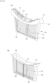
- FIG. 6 illustrates the detailed structure of the filter portion 10.
- the inner filter 100 may include a support body 110, which is seated on the mounting portion 178 and supported thereby, and a reception body 120, which extends downwards from the support body 110 and at least a portion of which is accommodated in the outer filter 200 or the mounting portion 178.
- the support body 110 may be constructed so as to correspond to the shape and the surface area of the mounting groove 1781, and may define a portion of the introduction port 173.
- the support body 110 may include an open surface 112 formed in the upper surface thereof through which air and foreign substances are introduced, and a plurality of screen ribs 111 shielding at least a portion of the open surface 112.
- the screen ribs 111 may be configured to block introduction of large-volume objects such as laundry in addition to air or small-volume foreign substances such as lint.
- the screen ribs 111 may be arranged in the open surface 112 like a mesh.
- the upper surface of the support body 110 may be provided with a coupler 160 configured to couple the support body 110 to the mounting portion 178 or to guide the installation and pulling direction of the inner filter 100.
- the surface area of the support body 110 may be larger than the surface area of the reception body 120.
- the support body 110 may include a seating surface 113, which is formed at the lower portion thereof and extends outwards from the upper surface of the reception body 120.
- the seating surface 113 may be supported by the upper portion of the mounting groove 1781 so as to prevent the inner filter 100 from falling into the mounting groove 1781.
- the reception body 120 may be constructed to have the form of a box which extends from the lower portion of the support body 110, and may provide therein a space in which foreign substances accumulates.
- the reception body may include a through hole formed in most of the surface area thereof, and a mesh portion 140 which is coupled to the through hole so as to remove foreign substances at the surface thereof.
- the mesh portion 140 may be constructed to have the form of a mesh coupled to the through hole formed in the reception body 120.
- the mesh portion 140 may be formed to occupy most of the surface area of the reception body 120. Due to the mesh portion 140, the reception body 120 may look a frame supporting the mesh portion 140.
- the reception body 120 may include a first reception body 121, which extends from the lower portion of the support body 110 and removes foreign substances, and a second reception body 122, which is rotatably coupled to the lower portion of the first reception body 121 so as to define a space, in which foreign substances accumulate, together with the first reception body 121.
- the first reception body 121 and the second reception body 122 may be separated from each other such that the inside of the reception body 120 is opened. Consequently, a user can remove foreign substances which are removed through the first reception body 121 and the second reception body 122 and accumulate in the reception body 120.
- the support body 110 may be composed of a portion coupled to the first reception body 121 and a portion coupled to the second reception body 122, which are detachably coupled to each other.
- the inner filter 100 may further include a reinforcing portion 150 which serves to reinforce the rigidity of the first reception body 121 and the second reception body 122.
- the reinforcing portion 140 may prevent deformation of the first reception body 121 and the second reception body 122 when the first reception body 121 and the second reception body 122 are inserted into the mounting portion 178.
- the reinforcing portion 150 may be disposed parallel to the width direction of the support body 110, and may be constructed to have the form of a rib.
- the reinforcing portion 150 may also serve as a hinge about which the first reception body 121 and the second reception body 122 are rotated.
- first reception body 121 and the second reception body 122 extend from the lower portion of the support body 110 to define a wedge shape
- the first reception body 121 and the second reception body 122 may be formed to have any shape as long as the first reception body 121 and the second reception body 122 can define therebetween a space for accumulation of foreign substances.
- the outer filter 200 may include a seating body 210 mounted on the mounting portion 178, and an insertion body 220 which extends downwards from the seating body 210 such that at least a portion of the insertion body 220 is inserted into the mounting portion 178 or the insertion body 220 receives the inner filter 100 therein.
- the seating body 210 may include an open surface 211 formed in the upper side thereof through which air and foreign substances are introduced, and a seating portion 213 which is seated on the upper portion of the mounting body 1782 and supported thereby.
- the open surface 211 may have such a surface area that the reception body 120 of the inner filter 100 is inserted and accommodated in the outer filter 200.
- the seating portion 213 may have a surface area larger than the surface area of the mounting body 1782 but smaller than the surface area of the mounting groove 1781 such that the seating portion 213 is seated on the upper surface of the mounting body 1782 and supported thereby when the seating portion 213 is accommodated in the mounting groove 1781.
- the insertion body 220 may extend downwards from the inner circumferential surface of the seating portion 213 so as to be inserted into the mounting body 1782.
- the insertion body 220 may be constructed to have the form of a case having a space in which foreign substances accumulate.
- a through hole may be formed in most of the surface area of the insertion body 220, and a mesh portion 240 may be coupled to the through hole in order to remove foreign substances.
- the mesh portion 240 may be made of a mesh or the like which allows air to pass therethrough but removes foreign substances.
- the mesh size of the mesh portion 240 may be smaller than the mesh size of the mesh portion 140.
- the inner filter 100 may remove relatively large substances while the outer filter 200 may remove relatively small foreign substances, thereby maximizing the filtration performance of the filter portion 100.
- the insertion body 220 may include a first insertion body 221 which extends from the lower portion of the seating body 210 and removes foreign substances, and a second insertion body 222 which is rotatably coupled to the lower portion of the first insertion body 221 and defines a space, in which foreign substances accumulate, together with the first insertion body 221.
- the insertion body 220 may be constructed such that the first insertion body 221 and the second insertion body 222 may be separated from each other such that the inside of the insertion body 220 is opened. Consequently, a user can remove foreign substances which are removed through the first insertion body 221 and the second insertion body 222.
- the seating body 210 may be composed of a portion coupled to the first insertion body 221 and a portion coupled to the second insertion body 222, which are detachably coupled to each other.
- the outer filter 200 may further include a reinforcing portion 250 which serves to reinforce the rigidity of the first insertion body 221 and the second insertion body 222 and which maintains the shapes of the first insertion body 221 and the second insertion body 222 when the first insertion body 221 and the second insertion body 222 are inserted into the mounting portion 178.
- a reinforcing portion 250 which serves to reinforce the rigidity of the first insertion body 221 and the second insertion body 222 and which maintains the shapes of the first insertion body 221 and the second insertion body 222 when the first insertion body 221 and the second insertion body 222 are inserted into the mounting portion 178.
- the reinforcing portion 250 may be formed to have the form of a rib which extends in the width direction of the seating body 210.
- the inner filter 100 and the outer filter 200 must be mounted on the mounting portion 178 together.
- FIG. 7 illustrates an embodiment which enables both the outer filter 200 and the inner filter 100 to be mounted on the mounting portion 178 together.
- both the inner filter 100 and the outer filter 200 should be mounted together.
- one of the inner filter 100 and the outer filter 200 of the clothing processing apparatus according to the present disclosure can be completely mounted only when the other of the inner filter 100 and the outer filter 200 is mounted on the mounting portion 178.
- mounting of the filter portion on the mounting portion 178 cannot be completed by the inner filter 100 alone, and cannot be completed by the outer filter 200 alone.
- the inner filter 100 it is physically impossible for the inner filter 100 to be completely mounted on the mounting portion 178 without the outer filter 200.
- the fact that the inner filter 100 and the outer filter 200 are not completely mounted on the mounting portion 178 may mean that the inner filter 100 and the outer filter 200 are shaken or vibrate when mounted on the mounting portion 178.
- the fact that the inner filter 100 and the outer filter 200 are not completely mounted on the mounting portion 178 may mean that the inner filter 100 and the outer filter 200 are not completely mounted on the mounting portion 178 and are thus taken out toward the introduction port 173.
- the clothing processing apparatus is able to induce a user to mount the other of the inner filter 100 and the outer filter 200 to the mounting portion 178.
- the clothing processing apparatus enables a user to physically recognize whether the inner filter 100 or the outer filter 200 alone is mounted before determining whether or not the filter portion 10 is mounted using a sensor or a signal generator in an electrical control manner.
- the outer filter 200 may be withdrawn from the mounting portion 178 when the inner filter 100 is not mounted on the mounting portion 178.
- the outer filter 200 may be withdrawn from the mounting portion 178 toward the introduction port 173. In other words, at least a portion of the outer filter 200 may escape from the mounting portion 178 when the inner filter 100 is not mounted on the mounting portion 178.
- the outer filter 200 may project from the mounting portion 178 to such an extent as to hinder closing of the opening 111 by the door 112. Accordingly, because the door 112 interferes with the outer filter 200 and thus cannot close the opening 111 when the outer filter 200 alone is mounted on the mounting portion 178, the clothing processing apparatus cannot be operated.
- the outer filter 200 when the outer filter 200 alone is mounted on the mounting portion 178, a user may find that the outer filter 200 is not completely mounted on the mounting portion 178 and may thus recognize that mounting of the inner filter 100 is required.
- the outer filter 200 may further include an elastic portion 260 which is supported by the mounting portion 178 so as to cause the outer filter 200 to be separated from the mounting portion 178.
- the elastic portion 260 may be embodied as an elastic element such as a spring, and may cause the outer filter 200 to be withdrawn from the mounting portion 178.
- FIG. 8 illustrates the detailed structure of the outer filter 200.
- the outer filter 200 may include the seating body 210 seated on the mounting portion 178, and the insertion body 220 which extends from the seating body so as to be at least partially inserted into the mounting portion and to which a mesh member configured to remove foreign substances is installed.
- the elastic portion 260 may be coupled to the seating body 210 so as to cause the seating body to be separated from the mounting portion 178.
- the elastic portion 260 may also be coupled to the upper surface of the mounting portion 178 so as to push out the seating body 210.
- the seating body 210 may further include the seating portion 213 which extends outwards from the insertion body 220 and is seated on the upper surface of the mounting portion.
- the seating portion 213 may be seated on the upper surface of the mounting body 1782, and the insertion body 220 may be accommodated in the mounting body 1782.
- the seating portion 213 may be formed to have a shape parallel to the upper surface of the mounting body 1782, and may be engaged therewith.
- the elastic portion 260 may serve to push out the lower surface of the seating portion 213 and the mounting portion 178 away from each other.
- the elastic portion 260 may be supported by the lower surface of the seating portion 213 and the upper surface of the mounting body 1782.
- the mounting portion 178 may further include a support surface 1783 which extends toward the inner circumferential surface of the mounting groove 1781 from the upper surface of the mounting body 1782.
- the elastic portion 260 may be coupled to one of the support surface 1783 and the lower surface of the seating portion 213 while being in contact with the other of the support surface 1783 and the lower surface of the seating portion 213.
- the elastic portion 260 may be coupled to the lower surfaces of the two lateral sides of the seating portion 213.
- the elastic portion 260 may have a sufficient length such that the seating body 210 is positioned higher than the mounting groove 1781.
- the outer filter 200 may include a signal generator 300 configured to generate signals, and the mounting portion 178 may include the sensor 400 configured to sense the signal generator 300.
- the sensor 400 may be embodied as a Hall sensor, and the signal generator 300 may include a magnetic body capable of generating a magnetic field.
- the signal generator 300 may be coupled to the insertion body 220, and may be provided at the lateral surface of the insertion body 220.
- the sensor 400 may be disposed on the outer surface of the mounting body 1782 so as to prevent interference with the outer filter 200.
- the sensor 400 and the signal generator 300 may be disposed at the same level.
- the controller may operate the clothing processing apparatus .
- the signal generator 300 may be spaced apart from the sensor 400, whereby the clothing processing apparatus cannot be operated.
- controller may be set to prevent operation of the clothing processing apparatus in the state in which the door 112 opens the opening 111.
- the outer filter 200 when the outer filter 200 alone is inserted into the mounting portion 178 without the inner filter 100, the outer filter 200 cannot be completely mounted on the mounting portion 178 and the clothing processing apparatus cannot be operated.
- the clothing processing apparatus cannot be operated when the inner filter 100 alone is mounted on the mounting portion 178 without the outer filter 200.
- the clothing processing apparatus may be operated only when both the inner filter 100 and the outer filter 200 are mounted on the mounting portion 178, and may forcibly induce the inner filter 100 and the outer filter 200 to be mounted on the mounting portion 178 together.
- FIG. 9 illustrates the state in which the elastic portion 260 is compressed.
- the elastic portion 260 may be compressed.
- the seating body 210 may be pushed towards the mounting portion 178 by external force applied from a user or the like, or may be pushed toward the mounting portion 178 by the inner filter 100 seated on the upper end of the seating body 210.
- the insertion body 220 may further be inserted into the mounting body 1782.
- the signal generator 300 coupled to the insertion body 220 may be moved downwards together with the insertion body 220, and may be disposed at a position corresponding to the sensor 400. Consequently, the clothing processing apparatus may be converted into the operable state.
- the seating body 210 may be withdrawn from the mounting portion 178 by the elastic force of the elastic portion 260.
- the clothing processing apparatus may be converted into the inoperable state.
- the inner filter 100 may maintain the state in which the outer filter 200 is mounted on the mounting portion 178 while overcoming the restoring force of the elastic portion 260.
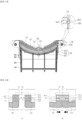
- FIG. 10 illustrates the state in which the inner filter 100 and the outer filter 200 are seated.
- FIG. 10(a) illustrates the state in which the inner filter 100 and the outer filter 200 are mounted.
- FIG. 10(b) illustrates the state in which the inner filter 100 and the outer filter 200 are completely mounted on the mounting portion 178.
- the inner filter 100 may further include the coupler 160 configured to fix the support body 110 to the mounting portion 178 to maintain the compressed state of the elastic portion 260.
- the inner filter 100 may be accommodated and seated in the outer filter 200.
- the elastic portion 260 may be compressed, and the seating body 210 of the outer filter 200 may be seated on the mounting body 1782.
- the coupler 160 may couple the inner filter 100 to the mounting portion 178 to maintain the positions of the inner filter 100 and the outer filter 200.
- the outer filter 200 may be completely mounted on the mounting portion 178, and the inner filter 100 may also be completely mounted on the mounting portion 178 by means of the coupler 160.
- the coupler 160 may be detachably coupled to the mounting portion 178, and may fix the inner filter 100 to the mounting portion 178.
- the coupler 160 may be coupled to the inner surface of the mounting groove 1781 which is positioned higher than the mounting body 1782.
- the coupler 160 may include a coupling hook 1613 which is capable of projecting from the support body 110 and which projects at least one of the two lateral surfaces of the support body 110.
- the inner filter 100 may include the seating surface 113 which is seated in the mounting groove 1781.
- the two lateral surfaces of the seating surface 113 may be formed so as to define a portion of the inner circumferential surface of the introduction port 173.
- the seating surface 113 may shield the inlet of the mounting portion 178 and may define a portion of the connecting body 177.
- the inner circumferential surface of the connecting body 177 and the upper surface of the support body 110 may define a continuous surface, and the upper surface of the support body 110 may define a portion of the introduction port 173.
- the components such as a door gasket, which is provided at the door 112 so as to be inserted into the introduction port 173, may not interfere with the support body 110.
- the door 112 may close the opening 111 without interfering with the support body 110.
- the compressed state of the elastic portion 260 may be maintained. Because the inner filter 110 is fixed to the mounting portion 178, the elastic portion 260 cannot push out the outer filter, and can be maintained in the state of pressing against the outer filter 200. Therefore, the outer filter 200 may not be taken out toward the introduction port 173, and may be maintained in the state of being completely mounted on the mounting portion 178.
- the support body 110 may be seated on the seating body 210 so as to transmit external force compressing the elastic portion 260, and the coupler 160 may project from two sides of the support body 110.
- the reception body 120 which extends from the support body 110 and at which the mesh member is installed, may be at least partially inserted into the outer filter 200 while the support body 110 is seated on the seating body 210.
- the inner filter 100 may be formed to have a shape corresponding to the shape of the mounting groove 1781.
- the inner filter 100 may not be engaged with the mounting portion or may be shaken in the mounted state.
- the outer surface of the inner filter may be formed to have a shape corresponding to the mounting groove 1781, the lower surface of the inner filter 100 and the inlet of the mounting groove 1781 may be shakable.
- the cross-sectional area of the reception body 120 may be greatly smaller than the cross-sectional area of the mounting duct 1782 such that the reception body 120 can be shaken forwards and backwards when the reception body 120 alone is accommodated in the mounting duct 1782.
- the inner filter 100 may be swung like a pendulum based on the coupler 160.
- the surface of the support body 110 may be constructed so as to provide the feeling of an appearance unified with the connecting body 177, the seating surface 113 of the support body 110 and the outer circumferential surface of the mounting groove 1781 may not be exactly engaged with each other.
- the seating surface 113 may be constructed so as to shield the mounting groove 1781, the seating surface 113 may be shaken on the outer circumferential surface of the mounting groove 1781 when the reception body 120 is shaken.
- the lower surface of the seating surface 113 may be curved based on the thickness direction or the forward/backward direction of the introduction port 111, and the periphery of the mounting groove 1781 may also be constructed such that the seating surface 113 is shakable.
- the support body 110 may also be shakable in the mounting groove 1781.
- the inner filter 100 cannot be fixed to the mounting groove 1781, a user is able to recognize that the outer filter 200 is required and thus to couple the inner filter 100 to the outer filter 200.
- the outer filter 200 may receive the inner filter 100 therein such that the inner filter 100 cannot be shaken.
- the outer filter 200 cannot be shaken once the outer filter 200 is seated on the mounting portion 178.
- the upper surface of the seating body 210 of the outer filter 200 may be formed to have a shape corresponding to the lower surface of the support body 110 of the inner filter 100 or the lower surface of the seating surface 113 of the support body 110. Accordingly, the seating body 210 may be in surface contact with the support body 110 or the seating surface 113 so as to support the support body 110.
- the lower surface of the seating body 210 may be formed to have a shape corresponding to the upper surface of the mounting duct 1782 such that the lower surface of the seating body 210 is seated on the upper surface of the mounting duct 1782 in a surface contact state.
- the seating body 210 may be fixed to the mounting portion 178 in the state of being incapable of shaking.
- the cross-section of the outer circumferential surface of the insertion body 220 may have a shape corresponding to the inner cross-section of the mounting body 1782 such that the insertion body 220 is supported by the mounting body 1782 in a state of being in contact therewith.
- At least a portion of the inner surface of the insertion body 220 may be in surface contact with the outer surface of the reception body 120 so as to support the outer surface of the reception body 120.
- At least a portion of the inner surface of the insertion body 220 may be in surface contact with the two surfaces (or the front and rear surfaces) of the reception body 120 so as to support the two surfaces of the reception body 120.
- the reception body 120 may be fixed without shaking once the reception body 120 is accommodated in the insertion body 220.
- the cross-section of the inner circumferential surface of the insertion body 220 may be formed to have a shape corresponding to the cross-section of the outer circumferential surface of the receiving body 120 and the cross-sectional area of the inner circumferential surface of the insertion body 220 may also correspond to the cross-sectional area of the outer circumferential surface of the receiving body 120 such that the reception body 120 is fixed in the insertion body 220 without independent movement.
- the outer filter 200 may maintain the state in which the inner filter 100 is fixed to the mounting portion 178.
- the outer filter 200 should be mounted on the mounting portion 178.
- the inner filter 100 should be mounted on the mounting portion 178.
- the signal generator 300 is not installed at the inner filter 100 but only at the outer filter 200, a user may be induced to mount the outer filter 200 on the mounting portion 178 because the clothing processing apparatus cannot be operated with the inner filter 100 alone.
- the coupler 160 of the inner filter 100 may include a guide case 115 configured to control the coupling hook 1613 to be mounted on or separated from the mounting portion 178, as indicated in region A, and may further include a component configured to selectively couple the mounting portion 178 and the coupling hook 1613 to each other, as indicated in region B.
- FIG. 11 illustrates a detailed embodiment of the coupler 160.
- the coupler 160 may include a coupling rib 161 which is reciprocated to the support body 110 in the support body 110
- the coupling hook 1613 may be formed at the distal end of the coupling rib 161.
- the support body 110 may include a movement rail 114 formed in or on the inner surface thereof so as to support the coupling rib 161 so as to be reciprocated.
- the movement rail 114 may extend in the width direction of the support body 110.
- the coupling rib 161 may be composed of a plurality of coupling ribs which are reciprocably movable between the two lateral surfaces of the support body and the inner surface of the mounting groove.
- the coupling hook 161 may include a plurality of coupling hooks which are formed at respective distal ends of the plurality of coupling ribs 161.
- the plurality of coupling ribs 161 may be movable toward the lateral surfaces of the support body 110 based on the guide case 115.
- the coupling ribs 161, which are disposed at one side of the guide case 115 may be reciprocated with respect to one lateral surface of the support body 110 whereas the coupling ribs 161, which are disposed at the other side of the guide case 115, may be reciprocated to the other lateral surface of the support body 110.
- the mounting portion 178 may further include coupling holes 1785 formed in the inner surface of the mounting groove 1781 such that the coupling hooks 1613 formed at the distal ends of the coupling ribs 161 are accommodated in and coupled to the coupling holes 1785.
- the coupling ribs 161 may move to the coupling holes 1785 such that the coupling hooks 1631 is inserted into the coupling holes 1785 to a sufficient depth.
- the coupling ribs 161 may move to the coupling holes 1785 such that the coupling hooks 1631 is inserted into the coupling holes 1785 to a sufficient depth.
- the coupling ribs 161 may move to the guide case 115 to completely retract the coupling hooks 1631 from the coupling holes 1785. Consequently, it is possible to prevent the mounting portion 178 from breaking when the inner filter 100 is separated from the mounting portion 178.
- the coupler 160 may further include an elastic member 162 which is disposed between the plurality of coupling ribs 161 so as to push out the plurality of coupling ribs toward the two lateral surfaces of the support body.
- the elastic member 162 may push out the coupling ribs 161 to insert the coupling hooks 1613 into respective coupling holes 1785, and may be installed at the guide case 115 so as to push out the coupling ribs 161.
- the elastic member 162 may be compressed between the plurality of coupling ribs 161, thereby generating force for pushing out the coupling ribs 161.
- the coupling ribs 161 may be separated from the mounting portion 178 while compressing the elastic member 162. Meanwhile, when the external force is released, the coupling ribs 161 may be moved back toward the outside of the support body 110 by means of the elastic member 162.
- each of the plurality of coupling ribs 161 may include a push portion 1611 to which the elastic member 162 is coupled, and an extension rib 1612 which extends to one of the two lateral surfaces of the support body 110 from the lower portion of the push portion 1611 and which is provided at the distal end thereof with the coupling hook 1613.
- the push portion 1611 may be exposed to the guide case 115 so as to allow a user to press the push portion.
- the push portion 1611 may be reciprocably movable in the guide case 115, and may be exposed to one of the two lateral surfaces of the guide case 115.
- the extension rib 1612 may extend to one of the two lateral surfaces of the support body 110 from the lower portion of the push portion 1611.
- the extension rib 1612 may be moved together with the push portion 1611.
- the elastic member 162 may be accommodated in the guide case 115 so as to be disposed between the plurality of push portions 1611.
- the movement rail 114 may be formed to have a shape corresponding to the extension rib 1612, and may slidably support the extension rib 1612.
- the coupling rib 161 may be supported by the guide case 115 and the movement rail 114 so as to be reciprocated.
- the guide case 115 may support the upper portion and the front surface or the rear surface of the push portion 1611, and may be formed to have the form of a duct which is open at the two lateral surfaces thereof so as to allow the lateral surface of the push portion 1611 to be exposed through the open surface.
- the lateral surface of the push portion 1611 may be exposed through the opening 112, and the shield rib 111 may be spaced apart from the guide case 115 by a predetermined distance so as to assure a space through which a user presses the lateral surface of the push portion 1611.
- the plurality of coupling ribs 161 may have the same length, and the guide case 115 may be disposed in the center of the support body 110. Consequently, a user is able to move the plurality of coupling ribs 161 using the same force.
- the signal generator 300 disposed at the filter portion 10 may be disposed at the same level as the sensor 400 coupled to the mounting portion 178 so as to overlap each other.
- the filter portion 10 When the coupling rib 161 is separated from the coupling hole 1785, the filter portion 10 may be retracted from the mounting portion 178 and may be disposed higher than the sensor 400 by the restoring force of the elastic portion 260.
- the push portion 1611, the extension rib 1612, and the coupling hook 1613 may be integrally formed, and may be made of resin or the like.
- the guide case 115 may have a space configured to receive the elastic member 162.
- the plurality of coupling ribs 161 may be spaced apart from each other in the guide case 115 by a retraction distance the coupling hooks 1613 are completely retracted or separated from the mounting grooves.
- the elastic member 162 may have a longer length than the retraction distance, and the guide case 115 may also have a longer width than the retraction distance.
- the coupling ribs 161 may provide force to continuously press the elastic portion 260.
- the rigidity of the coupling ribs 161 is higher than the elastic force of the elastic portion 260, it is possible to maintain the state in which the elastic portion 260 is sufficiently pressed.
- the coupler 160 may maintain the state in which the outer filter 200 is mounted on the mounting portion 178.
- FIG. 12 illustrates operation of the coupling ribs.
- the coupling ribs 161 may include a plurality of coupling ribs, and may be supported by the guide case 115 and the movement rail 114.
- the guide case 115 may support the coupling ribs 161 such that the push portions of the coupling ribs 161 are reciprocated in the width direction.
- the plurality of coupling ribs 161 may be spaced apart from each other by a distance corresponding to the retraction distance or more.
- the push portions 1611 which are provided at respective coupling ribs 161, may also be reciprocably movable in the guide case 115 by the retraction distance.
- each of the push portions 1611 may be constructed to have the form of a case which is open at one side thereof so as to receive at least a portion of the elastic member 162 therein.
- the push portion 1611 may include a holding protrusion 1611d configured to retain the position of the elastic member 162
- the push portion 1611 may include a connecting surface 1611c, which extends from the extension rib 1612 or is coupled to the extension rib 1612, a press surface 1611b, which extends from the connecting surface 161 1 c so as to be pressed by a user and at which the holding protrusion 1611d is installed, and an extension surface 1611a, which extends from the press surface 1611b so as to be supported by the guide case 115.
- An open surface may be positioned at the side of the push portion 1611 opposed to the press surface 1611b. Consequently, the open surfaces of the plurality of push portions 1611 may face each other.
- the inner surfaces of the extension ribs 1612 and the push portions 1611 may be spaced apart from each other by a distance twice the retraction distance or more.
- each of the extension ribs 1612 can be separated from a corresponding coupling hole 1785 when the extension rib 1612 is moved by the retraction distance or more. Accordingly, the left extension rib 1612 can be moved to the right by the retraction distance or more, and the right extension rib 1612 can also be moved to the left by the retraction distance or more.
- the elastic portion 162 may be compressed as the plurality of push portions 1611 comes close to each other.
- the elastic portion 162 may serve to push out the push portions 1611 when the external force applied to the push surfaces 1611b is released.
- the coupler 160 may be operated even without separate electronic control.
- a user may mount or separate the inner filter 100 to or from the mounting portion 178 by selectively pressing the press surfaces 1611b of the push portions 1611 which are exposed through the two lateral sides of the guide case 115.
- the clothing processing apparatus is able to induce both the inner filter 100 and the outer filter 200 to be simultaneously coupled in an electronic control manner, in addition to the above-mentioned physical manner.
- the clothing processing apparatus according to the present disclosure may be set to be operated only when both the inner filter 100 and the outer filter 200 are simultaneously mounted.
- the signal generator 300 configured to generate a signal may be installed at at least one of the inner filter 100, the outer filter 200 or the mounting portion 178, and the mounting portion 178 may include the sensor 400 configured to sense the signal generator 300 to determine whether or not the filter portion 10 is mounted.
- the signal generator 300 may be reciprocated along one surface of one of the mounting portion, the outer filter and the inner filter.
- the signal generator 300 may be moved in a sliding manner such that the signal generator 300 overlaps the sensor 400 or is completely spaced apart from the sensor 400
- the senor 400 may precisely sense variation in position of the signal generator 300, thereby making it possible to more precisely determine whether or not the filter portion 10 is mounted.
- the signal generator 300 When the signal generator 300 moves in the height direction or in the insertion and retraction direction of the filter portion 10, the signal generator 300 may move in the state of contacting the filter portion 10 without interfering with insertion and retraction of the filter portion 10.
- the signal generator 300 may be moved toward the sensor 400 when the outer filter 100 or the inner filter 200 is mounted on the mounting portion 178. Furthermore, the signal generator 300 may be moved so as not to overlap the sensor 400 when the outer filter 100 or the inner filter 200 is withdrawn from the mounting portion 178.
- the signal generator 300 may include a magnet 320 configured to generate a magnetic field, a guide rail 310 having a space in which the magnet 320 is reciprocated, and a restoring portion 330, which is installed at the guide rail 310 so as to support the magnet 320.
- the guide rail 310 may extend from a position at which the guide rail 310 overlaps the sensor 400 to a position at which the guide rail 310 does not overlap the sensor 400.
- the guide rail 310 may be positioned such that one end thereof overlaps the sensor 400 and the other end thereof does not overlap the sensor 400.
- the magnet 320 may be received in the guide rail 310, and may be reciprocated between one end and the other end of the guide rail 310.
- the magnet 320 may be disposed at a position on the guide rail 310 at which the magnet 320 does not overlap the sensor 400, the magnet 320 may be moved to a position at which the magnet 320 overlaps the sensor 400 by the filter portion 10.
- the restoring portion 330 may be received in the guide rail 310 so as to push the magnet 320 to a position at which the magnet 320 does not overlap the sensor 400.
- the restoring portion 330 may be made of an elastic element such as a spring.
- the sensor 400 may be provided on the outer surface of the mounting duct 1782 so as not to overlap a certain region of the guide rail 310.
- the senor 400 may also be provided on the inner surface of the mounting duct 1782 as long as the sensor 400 does not interfere with movement of the filter portion 10.
- FIG. 13 illustrates an embodiment of the signal generator and the sensor of the clothing processing apparatus according to the present disclosure.
- Both the signal generator 300 and the sensor 400 may be installed at the mounting portion 178.
- the signal generator 300 may be provided on the inner circumferential surface of the mounting portion 178, and may be moved toward the sensor 400 in an up-and-down direction by the outer filter 200.
- the guide rail 310 of the signal generator 300 may be provided at the mounting duct 1782.
- the guide rail 310 may be exposed to the inside of the mounting duct 1782, and may project toward the outside of the mounting duct 1782.
- the guide rail 310 may extend downwards from the upper surface of the mounting duct 1782, and may be disposed lower than the seating body 210 when the seating body 210 is supported by the mounting duct 1782.
- the magnet 320 When the outer filter 200 is coupled, the magnet 320 may come into contact with the outer filter 200 and may be moved to the lower portion of the guide rail 310.
- both the signal generator and the sensor are installed at the mounting portion 178, it is possible to relatively simply manufacture the filter portion 10 and to easily perform repair and replacement of the filter portion 10.
- FIG. 14 illustrates operation of the signal generator and the sensor shown in FIG. 13 .
- FIG. 14(a) illustrates the cross-section when the outer filter 200 begins to be mounted on the mounting portion 178.
- FIG. 14(b) illustrates the cross-section when viewed from the front.
- the guide rail 310 may be constructed to have the form of a duct in which the magnet 320 is exposed to the inside of the mounting duct 1782.
- the guide rail 310 may extend downwards from a position lower than the support surface 1783.
- a portion of the magnet 320 may be received in the guide rail 310, and another portion of the magnet 320 may project to the inside of the mounting duct 1782 from the guide rail 310 so as to come into contact with one of the seating body 210 or the insertion body 220.
- the restoring portion 330 may be supported by the lower surface of the inside of the guide rail 310 so as to push the magnet 320 upwards.
- the sensor 400 may be disposed outside the guide rail 310 so as to overlap the guide rail 310 in the state of being biased to the lower portion of the guide rail 310.
- the sensor 400 When the outer filter 200 is mounted so as to press the magnet 320, the sensor 400 may be disposed at a position at which the sensor 400 faces the magnet 320.
- the sensor 400 may be disposed outside the mounting duct 1782.
- the outer filter 200 When the outer filter 200 is inserted into the mounting duct 1782, the outer filter 200 may press the magnet 320.
- the lower surface of the seating body 210 may press the magnet 320.
- another component of the outer filter 200 such as the insertion body 220, may also press the magnet 320.
- the lower surface of the seating body 210 may move the magnet 320 downwards such that the magnet 320 overlaps the sensor 400.
- the sensor 400 may determine that the outer filter 200 is completely mounted on the mounting portion 178 by sensing the magnet 320.
- the magnet 320 may be moved upwards by means of the restoring portion 330 because the outer filter 200 cannot press the magnet 320 anymore.
- the senor 400 may not sense the magnet 320, and the controller may recognize that the outer filter 200 is not completely mounted on the mounting portion 178.
- the controller may determine whether both the inner filter 100 and the outer filter 200 are simultaneously mounted by means of the signal generator 300.
- the controller may recognize that at least one of the inner filter 100 or the outer filter 200 is not mounted on the mounting portion 178 and may not permit operation of the clothing processing apparatus , by sensing only that the sensor 400 does not sense the magnet 320.
- a user may be induced to mount both the inner filter 100 and the outer filter 200 on the mounting portion 178.
- FIG. 15 illustrates another embodiment of the signal generator and the sensor.
- the signal generator 300 may be installed at the outer filter 200.
- the signal generator 300 may be provided on the inner surface of the outer filter 200 so as to be moved downwards by the inner filter 100.
- the sensor 400 may be installed at the mounting portion 178.
- the sensor 400 may be installed at such a position at which the sensor 400 senses the signal generator 300 when the outer filter 200 is completely mounted on the mounting portion 178 and then the inner filter 100 is mounted in the outer filter 200.
- the signal generator 300 may be installed in the outer filter 200.
- the guide rail 310 may be provided on the inner surface of the insertion body 220 such that the magnet 320 is exposed to the inside of the insertion body 220.
- the guide rail 310 may extend in an up-and-down direction on the inner surface of the insertion body 220.
- the guide rail 310 may be coupled to only one of the two divided insertion bodies 220 so as not to interfere with separation and coupling of the two divided insertion bodies 220.
- the magnet 320 may be moved in an up-and-down direction along the guide rail 310 in the state in which at least a portion of the magnet 320 is received in the guide rail 310.
- the restoring portion 330 may be coupled to the inner and lower surface of the guide rail 310 so as to push the magnet 320 upwards.
- the guide rail 310 may be formed to have a form of a slit supporting the two lateral surfaces of the magnet t320, and may further include a stepped portion to prevent the magnet 320 from escaping outwards.
- the inner filter 100 may move the magnet 320 to the lower portion of the guide rail 310.
- the outer filter 200 with the inner filter 100 received therein is mounted on the mounting portion 178, the magnet 320 may be disposed at a position corresponding to the sensor 400.
- the senor may sense the magnet 320, and the controller may recognize that both the inner filter 100 and the outer filter 200 are simultaneously coupled to the mounting portion 178.
- the magnet 320 may not overlap the sensor 400 because the guide rail 310 is moved upwards. Furthermore, when the inner filter 100 alone is mounted on the mounting portion 178, the sensor 400 may not sense the magnet 320.
- the controller may recognize that at least one of the inner filter 100 or the outer filter 200 is not mounted on the mounting portion 178 and may not permit operation of the clothing processing apparatus , by sensing only that the sensor 400 does not sense the magnet 320.
- a user may be induced to mount both the inner filter 100 and the outer filter 200 on the mounting portion 178.
- FIG. 16 illustrates the configuration in which the inner filter 100 moves the magnet 320 downwards.
- the inner filter 100 may press the magnet 320 in the course of being received in the outer filter 200.
- the inner filter 100 may include an upper protrusion 125 which projects from the outer surface of the inner filter 100 to push the magnet 320 of the signal generator 300 downwards.
- the reception body 120 may press the magnet 320.
- the upper protrusion 125 may be provided on the outer surface of the reception body 120 so as to come into contact with the magnet 320.
- At least a portion of the upper protrusion 125 may come into contact with the magnet 310 while the inner filter 100 is inserted into the outer filter 200.
- the upper protrusion 125 may be positioned so as to lower the magnet 310 to the maximum when the inner filter 100 is completely received in the outer filter 200.
- the upper protrusion 125 may project outwards from the lateral surface of the reception body 120 such that the upper protrusion 125 does not interfere with reception of the reception body 120 in the outer filter 200.
- the restoring portion 330 may be compressed.
- the magnet 320 may be positioned so as to overlap the sensor 400.
- FIG. 17 illustrates a further embodiment of the signal generator and the sensor.
- the signal generator 300 may be installed at the inner filter 100.
- the signal generator 300 may be provided on the outer surface of the inner filter 100 so as to be moved upwards by the outer filter 200.
- the sensor 400 may be installed at the mounting portion 178.
- the sensor 400 may be installed at a position at which the sensor 400 senses the signal generator 300 when the outer filter 200 is completely mounted on the mounting portion 178 and the inner filter 100 is mounted to the outer filter 200.
- the signal generator 300 may be installed outside the inner filter 100.
- the guide rail 310 may be provided on the outer surface of the reception body 120 such that the magnet 320 is exposed to the outside of the reception body 120.
- the guide rail 310 may extend in an up-and-down direction on the outer surface of the reception body 120.
- the guide rail 310 may be coupled to only one of the two divided reception bodies 120 so as not to interfere with separation and coupling of the two divided reception bodies 120.
- the magnet 320 may be moved in an up-and-down direction along the guide rail 310 in the state in which at least a portion of the magnet 320 is received in the guide rail 310.
- the restoring portion 330 may be coupled to the inner and upper surface of the guide rail 310 so as to push the magnet 320 downwards.
- the guide rail 310 may be formed to have a form of a slit supporting the two lateral surfaces of the magnet 320, and may further include a stepped portion to prevent the magnet 320 from escaping outwards.
- the outer filter 200 may move the magnet 320 to the upper portion of the guide rail 310.
- the outer filter 200 with the inner filter 100 received therein is mounted on the mounting portion 178, the magnet 320 may be disposed at a position corresponding to the sensor 400.
- the senor may sense the magnet 320, and the controller may recognize that both the inner filter 100 and the outer filter 200 are simultaneously coupled to the mounting portion 178.
- the sensor 400 may not sense the magnet 320.
- the magnet 320 does not overlap the sensor 400 because the magnet 320 is not moved upwards.
- the controller may recognize that at least one of the inner filter 100 or the outer filter 200 is not mounted on the mounting portion 178 and may not permit operation of the clothing processing apparatus , by sensing only that the sensor 400 does not sense the magnet 320.
- a user may be induced to mount both the inner filter 100 and the outer filter 200 on the mounting portion 178.
- FIG. 18 illustrates the configuration in which the outer filter 200 shown in FIG. 17 moves the magnet 320 upwards.
- the outer filter 200 may press the magnet 320 in the course of receiving the inner filter 100.
- the insertion body 220 may press the magnet 320.
- the outer filter 200 may include a lower protrusion 225 which projects from the inner surface of the outer filter 200 to push the magnet 320 of the signal generator 300 upwards.
- the insertion body 220 may further include the lower protrusion 225 on the inner surface thereof, which comes into contact with the magnet 320.
- At least a portion of the lower protrusion 225 may come into contact with the magnet 310 while the inner filter 100 is inserted into the outer filter 200.
- the lower protrusion 225 may be positioned so as to raise the magnet 310 to the maximum when the inner filter 100 is completely received in the outer filter 200.
- the lower protrusion 225 may project inwards from the lateral surface of the insertion body 220 but may not come into contact with the inner filter 100. Accordingly, the lower protrusion 225 may not interfere with reception of the inner filter 100 in the outer filter 200.
- the restoring portion 330 may be compressed.
- the magnet 320 may be positioned so as to overlap the sensor 400.
Landscapes
- Engineering & Computer Science (AREA)
- Textile Engineering (AREA)
- Detail Structures Of Washing Machines And Dryers (AREA)
Abstract
Description
- The present disclosure relates to a clothing processing apparatus , and more particularly to a clothing processing apparatus including a filter cartridge configured to remove foreign substances from air.
- Recently, a clothing processing apparatus designed to perform a drying procedure capable of removing moisture from laundry has been suggested. The conventional clothing processing apparatus is configured to supply hot air to a drum receiving laundry therein to dry the laundry, thereby not only remarkably reducing time required to dry the laundry but also performing disinfection and sterilization of the laundry.
- The conventional clothing processing apparatus may use an electrical heater in order to supply hot air to the drum. Accordingly, it is possible to create hot air by installing a heater at a duct communicating with the drum to heat the air introduced into the drum.
- Recently, a clothing processing apparatus designed to heat air introduced into a drum using a heat pump system has been suggested. The clothing processing apparatus is able to create dry and hot air by cooling air discharged from laundry to condense moisture using an evaporator and by heating the air again using a condenser.
- The clothing processing apparatus equipped with the heat pump system has advantages of having higher energy efficiency than a clothing processing apparatus equipped with an electrical heater, of being simplified in installation, and of being easier to repair and replace.
- However, the conventional clothing processing apparatus develops a problem in that air discharged from laundry directly collides with an evaporator and thus foreign substances such as lint adhere to the evaporator. Accordingly, there is a problem in that the foreign substances adhering to the evaporator hinder heat exchange between cool refrigerant flowing through the evaporator and the air discharged from the drum, thereby deteriorating drying efficiency.
- Particularly, when foreign substances remaining in the evaporator are decomposed by bacteria or the like, there is a problem in that the laundry received in the drum is also contaminated.
- In order to prevent this problem, a clothing processing apparatus equipped with a filter portion configured to filter foreign substances such as lint or dust which may be introduced into the evaporator has been suggested (see
Korea Unexamined Patent Publication No. 10-2017-0009657 - The clothing processing apparatus is provided with a filter portion detachably mounted thereon, thereby filtering foreign substances and enabling a user to separate the filter portion and remove foreign substances collected in the filter portion.
- The filter portion may be embodied as double filters configured to filter foreign substances having different sizes in order to improve foreign substance removal ability. The double filters are able to filter lint or dust having different sizes.
- In the case of double type filter portion, the inner filter should be mounted after the outer filter is mounted. However, the conventional clothing processing apparatus has the high possibility that the clothing processing apparatus is used in the state of only the outer filter or the inner filter being mounted due to user's carelessness.
- Particularly, because the outer filter is mounted on the mounting portion, which is formed at the introduction port so as to have a stepped shape, so as not be exposed to the outside, there are many cases in which a user uses the clothing processing apparatus in the state in which only the inner filter is mounted on the mounting portion.
- Consequently, there is a problem in that fine lint and dust having passed through the inner filter cannot be filtered by the outer filter and lint and dust generated from laundry is introduced into the drum receiving laundry therein or accumulates in a heat exchanger.
- In order to solve this problem, a clothing processing apparatus designed to be operated only when both the outer filter and the inner filter are mounted together has been suggested (
Korea Unexamined Patent Publication No. 10-2021-0128702 - The clothing processing apparatus is constructed such that a magnet is installed at the filter portion and a sensor such as a Hall sensor configured to sense the magnet is installed at the mounting portion. Accordingly, the clothing processing apparatus can be operated only when the sensor senses the magnet of the filter portion, thereby inducing a user to couple the filter portion to the mounting portion.
- However, because the clothing processing apparatus is constructed such that the inner filter and the outer filter are respectively provided with magnets and the sensor must sense all of the two magnets or the state of the two magnets overlapping each other, there is a problem in that it is difficult to exactly determine whether the inner filter and the outer filter are mounted.
- Accordingly, when one of the magnets is disposed at the same level as the sensor in the case in which only the inner filter is mounted or only the outer filter is mounted, there is a problem in that the clothing processing apparatus is operated because the sensor wrongly determines that all of the magnets disposed at the inner filter and the outer filter are positioned.
- Furthermore, when the magnet provided at the inner filter does not exactly overlap the magnet provided at the outer filter due to tolerance in installation, there is a problem in that the clothing processing apparatus is not operated because the sensor cannot sense sufficient magnetic force even when both the inner filter and the outer filter are installed.
- In other words, in the case in which a plurality of magnets are used as in the conventional clothing processing apparatus , there is a problem in that reliability of the sensor is not normally assured because resolution of the sensor is lowered.
- Furthermore, the conventional clothing processing apparatus also proposes a configuration in which a cantilever-type magnet is provided in the outer filter and the inner filter pushes out the cantilever-type magnet such that the sensor determines mounting of the two filters by sensing only the one magnet.
- However, in the case in which the cantilever is bent due to the weight of the magnet or is bent toward the sensor at a certain angle due to temporary vibration even when the inner filter is not mounted to the outer filter, there is a problem in that the sensor senses the magnet of the bent cantilever, thus incorrectly determining that the inner filter is mounted.
- Furthermore, there is a problem in that the cantilever interferes with introduction and retraction of the inner filter or breaks.
- As a result, the conventional clothing processing apparatus determines whether both the inner filter and the outer filter are mounted, not in a physical manner but in an electronic control manner using the sensor and the magnet, there is a problem in that it is impossible to assure reliability.
- An object to be solved according to the present disclosure is to provide a clothing processing apparatus capable of determining whether both an outer filter and an inner filter are coupled, in a physical manner.
- An object to be solved according to the present disclosure is to provide a clothing processing apparatus which enables a user to determine whether the outer filter or the inner filter is not coupled, in a physical manner.
- An object to be solved according to the present disclosure is to provide a clothing processing apparatus which makes it impossible for the outer filter or the inner filter alone to be mounted.
- An object to be solved according to the present disclosure is to provide a clothing processing apparatus which, even when a magnet is installed at the outer filter or the inner filter, prevents the magnet or a component supporting the magnet from interfering movement of the outer filter or from being moved to the sensor by the weight thereof.
- In order to solve above-mentioned objects, the present disclosure provides a clothing processing apparatus including a double type filter portion. The double type filter portion may be constructed such that one of the two filters cannot be completely mounted until the other of the two filters is mounted. In other words, in order to complete mounting of all of the filters, all of the filters should be disposed.
- For example, the filter portion may include an outer filter which is seated on a mounting portion so as to remove foreign substances introduced into a circulation duct, and an inner filter mounted on the mounting such that at least a portion of the inner filter is received in the outer filter. The outer filter may be separable at at least partially from the mounting portion until the inner filter is mounted on the mounting portion.
- Specifically, operation of the clothing processing apparatus may be blocked while mounting of the outer filter is not completed. For example, the clothing processing apparatus according to the present disclosure may include a signal generator coupled to the filter portion so as to generate an external signal, a sensor provided at the mounting portion so as to sense the signal generator, and a controller configured to permit operation of at least one of the heat supply portion or the driving portion when the sensor senses the signal generator, and the signal generator may be installed at the outer filter.
- The outer filter may include an elastic portion configured to separate the outer filter when the outer filter alone is mounted. Accordingly, the outer filter may not be completely mounted when the inner filter is not mounted.
- Specifically, the outer filter may include a seating body seated on the mounting portion, and an insertion body which extends from the seating body to be inserted at at least a portion thereof into the mounting portion and at which a mesh member is installed, and the seating body may include an elastic portion.
- The elastic portion may be configured to cause the seating body to be taken out of the mounting portion, thereby preventing the door from closing the opening.
- To this end, the seating body may be capable of projecting to an inside of the introduction port by means of the elastic portion. The seating body may include a seating portion which extends outwards from the insertion body and is seated on an upper surface of the mounting portion, and the elastic portion may be coupled to a lower surface of the seating portion so as to come into contact with the upper surface of the mounting portion.
- The inner filter may include a coupler configured to fix the outer filter to the mounting portion to prevent separation of the outer filter.
- For example, the inner filter may include a support body seated on the seating body and pressing the elastic portion, and a reception body which extends from the support body and at which a mesh member is installed, at least a portion of the reception body being inserted into the outer filter, and the coupler may fix the support body to the mounting portion and maintain the pressed state of the elastic portion.
- The mounting portion may include a mounting groove which is formed through an inner circumferential surface of the introduction port and by which the filter portion is supported, and a mounting body which extends to the circulation duct from the mounting groove and which receive the filter portion, the sensor being installed on an outer circumferential surface of the mounting body, and the coupler may include a coupling hook which projects from a lateral surface of the support body and is detachably coupled to an inner surface of the mounting groove.
- Specifically, the coupler may include a coupling rib which is provided at the support body so as to be reciprocated to the inner surface of the mounting groove, and the coupling hook may be formed at a distal end of the coupling rib.
- The coupler may include a plurality of coupling ribs which are reciprocated to the inner surface of the mounting groove from two lateral surfaces of the support body, and an elastic member provided between the plurality of coupling ribs so as to push the plurality of ribs toward the two lateral surfaces of the support body, and the coupling hook may be formed at a distal end of each of the plurality of coupling ribs.
- Each of the plurality of coupling ribs may include a push portion to which the elastic member is coupled, and an extension rib which extends toward a corresponding one of the two lateral surfaces of the support body and the distal end of which is provided with the coupling hook, and the support body may include a guide case which receives the elastic member at an upper surface thereof and which exposes the push portions through two lateral sides thereof.
- The plurality of coupling ribs may be spaced apart from each other by a distance corresponding to a distance the coupling hooks in the guide case are separated from the mounting groove.
- The support body may include movement rails which extend in a width direction thereof and guide the plurality of coupling ribs.
- The sensor may be disposed at a position corresponding to the signal generator when the coupler fixes the support body to the mounting portion.
- In order to solve the above-mentioned objects, one of the outer filter and the inner filter may be completely mounted on the mounting portion when the other of the outer filter and the inner filter is mounted on the mounting portion.
- The inner filter may be shakable and thus not be fixed when the inner filter alone is mounted on the mounting portion.
- The inner filter may include a support body seated on an upper surface of the outer filter, and a reception body which extends from the support body and at least a portion of which is inserted into the outer filter or the mounting portion, and the support body may be shakable on an upper surface of the mounting portion when the support body is mounted on the mounting portion.
- The outer filter may receive the inner filter therein and fix the inner filter.
- The outer filter may include a seating body seated on the mounting portion without shaking, and an insertion body which extends from the seating body and is seated on the mounting portion and which receives the reception body, and at least a portion of an inner surface of the insertion body may contact and support an outer surface of the reception body.
- The outer filter may be removeable from the mounting portion when the inner filter is not mounted on the mounting portion.
- The inner filter may be fixed to the mounting portion in a state of pressing the outer filter.
- In order to solve the above-mentioned objects, the clothing processing apparatus according to the present disclosure may be constructed such that the signal generator is reciprocatedalong one surface of one of the mounting portion, the outer filter and the inner filter.
- The signal generator may be moved toward the sensor when the outer filter or the inner filter is seated on the mounting portion.
- The signal generator may be provided on an inner circumferential surface of the mounting portion, and may be moved in an up-and-down direction toward the sensor by the outer filter.
- The signal generator may be provided on an inner surface of the outer filter so as to be moved downwards by the inner filter.
- The inner filter may include an upper protrusion which projects from an outer surface thereof and which pushes the signal generator downwards.
- The signal generator may be provided on an outer surface of the inner filter so as to be moved upwards by the outer filter.
- The outer filter may include a lower protrusion which projects from an inner surface thereof and which pushes the signal generator upwards.
- The signal generator may include a magnet interacting with the sensor, a guide rail installed at an inner surface of the mounting portion, the outer filter, and the inner filter, and a restoring portion installed at the guide rail so as to push the magnet upwards or downwards.
- The present disclosure has an effect of being capable of accurately sensing or determining whether both the outer filter and the inner filter are mounted.
- The present disclosure has an effect of being capable of determining whether both the outer filter and the inner filter are coupled, in a physical manner.
- The present disclosure has an effect of being capable of determining whether the outer filter or the inner filter is not coupled, in a physical manner.
- The present disclosure has an effect of inducing a user to mount both the outer filter and the inner filter.
- The present disclosure has an effect of assuring reliability and durability even when movement of the magnet and the sensor configured to sense the movement are utilized.
-
-
FIG. 1 illustrates a structure of a filter of a conventional clothing processing apparatus ; -
FIG. 2 illustrates the appearance of the clothing processing apparatus according to an embodiment of the present disclosure; -
FIG. 3 illustrates the internal structure of the clothing processing apparatus according to the present disclosure; -
FIG. 4 illustrates the state in which a filter portion according to an embodiment of the present disclosure is mounted; -
FIG. 5 illustrates the state in which the filter portion is taken out; -
FIG. 6 illustrates the detailed structure of thefilter portion 10; -
FIG. 7 illustrates an embodiment in which both anouter filter 200 and aninner filter 100 are capable of being mounted on a mountingportion 178; -
FIG. 8 illustrates the detailed structure of theouter filter 200; -
FIG. 9 illustrates an embodiment in which anelastic portion 260 is compressed; -
FIG. 10 illustrates the state in which theinner filter 100 and theouter filter 200 are seated; -
FIG. 11 illustrates a detailed embodiment of acoupler 160; -
FIG. 12 illustrates operation of a coupling rib; -
FIG. 13 illustrates an embodiment of a signal generator and a sensor of the laundry treatment according to the present disclosure; -
FIG. 14 illustrates operation of the signal generator and the sensor which are shown inFIG. 13 ; -
FIG. 15 illustrates another embodiment of the signal generator and the sensor; -
FIG. 16 illustrates a structure in which theinner filter 100 shown inFIG. 15 moves themagnet 320 downwards; -
FIG. 17 illustrates a further embodiment of the signal generator and the sensor; and -
FIG. 18 illustrates a structure in which theouter filter 200 shown inFIG. 17 moves themagnet 320 upwards. - Hereinafter, embodiments disclosed in this specification will be described in detail with reference to the accompanying drawings. In this specification, the same or equivalent components may be denoted by the same reference numbers even in different drawings, and a description thereof will not be repeated. Singular forms as used herein are intended to include plural forms as well, unless the context clearly indicates otherwise. Furthermore, in the following description of embodiments disclosed herein, if it is decided that a detailed description of known functions or configurations related to the present disclosure would make the subject matter of the present disclosure unclear, such detailed description is omitted. The accompanying drawings are used merely to assist in easy understanding of various technical features, and it should be understood that the technical idea presented in this specification should not be construed as being limited by the accompanying drawings.
- Hereinafter, a clothing processing apparatus according to an embodiment of the present disclosure will be described in detail with reference to the accompanying drawings.
-
FIG. 2 illustrates the appearance of the clothing processing apparatus according to the embodiment of the present disclosure. - The clothing processing apparatus according to the present disclosure includes a cabinet 1, a drum 2 which is rotatably provided in the cabinet and provides a space configured to store laundry therein, a
circulation duct 3 defining a flow channel configured to supply the air, discharged from the drum 2, back to the drum 2, and aheat exchanger portion 4 configured to dehumidify and heat the air into thecirculation duct 3 and to supply the dehumidified air to the drum 2. - The cabinet 1 may include a
front panel 11 defining the front surface of the clothing processing apparatus . Thefront panel 11 may be provided with anopening 111 communicating with the drum 2 and adoor 112 rotatably coupled to the cabinet so as to open and close theopening 111. - The
front panel 11 may be provided with acontrol panel 117. Thecontrol panel 117 may be provided with aninput portion 118, through which control commands are input from a user, and adisplay portion 119 to which information, such as control commands which are selectable by the user, is output. - The
control panel 117 may further include a controller or may be connected to the controller. The controller may control theinput portion 118 and thedisplay portion 119 or may control all electronic components such as a driving portion, the heat exchanger portion, awasher 6 and asensor 400 which will be described later. - The controller may generate a command for activating the clothing processing apparatus . For example, the controller may control at least one of the driving portion or the heat exchanger portion to enable the clothing processing apparatus to perform a drying procedure configured to remove moisture from the laundry.
- The
input portion 118 may include a power supply request portion configured to request supply of power, a course input portion configured to enable a user to select a desired course among a plurality of courses, and an execution request portion configured to request initiation of the course selected by the user. - A command for operating the clothing processing apparatus may be input through the
input portion 118, and may be transmitted to the controller. The controller may control various electronic components of the clothing processing apparatus in response to the command. - The
display portion 119 may include one of a display panel capable of outputting text and graphics and a speaker capable of outputting voice signals and sound. -
FIG. 3 illustrates the internal structure of the clothing processing apparatus according to the present disclosure. - The
clothing processing apparatus 100 according to the present disclosure includes a cabinet 1, a drum 2 which is rotatably provided in the cabinet and provides a space configured to store laundry therein, acirculation duct 3 defining a flow channel configured to supply the air, discharged from the drum 2, back to the drum 2, and aheat exchanger portion 4 configured to dehumidify and heat the air into thecirculation duct 3 and to supply the dehumidified air to the drum 2. - When the drum 2 includes a
drum body 21 having the form of a circular cylinder which is open at the front and rear surfaces thereof, the cabinet 1 may be provided therein with afirst support 17 configured to rotatably support the front surface of the drum 2 and asecond support 19 configured to rotatably support the rear surface of the drum 2. - The
first support 17 may include a firstfixed body 171 which is fixed in the cabinet 1, and anintroduction port 173 which is formed through the first fixed body so as to allow theopening 111 to communicate with the inside of thedrum body 21. - The
first support 17 may further include afirst support body 175 which is provided at the firstfixed body 171 and is inserted into the front side of thedrum body 21. - The first
fixed body 171 may be formed to have any shape as long as it includes theintroduction port 173 and thefirst support body 175. Thefirst support body 175 may be formed to have the form of a pipe which projects toward thedrum body 21 from the firstfixed body 171. The diameter of thefirst support body 175 may be set to be larger than the diameter of theintroduction port 173 but smaller than the diameter of the front surface of thedrum body 21. Here, theintroduction port 173 may be positioned in the space defined by thefirst support body 175. - The
first support 17 may further include a connectingbody 177 connecting theopening 111 to theintroduction port 173. The connectingbody 177 may be formed to have the form of a pipe which extends toward the opening 111 from theintroduction port 173. The connectingbody 177 may be provided with a mountingportion 178 communicating with thecirculation duct 3. The mountingportion 178 may be a passage which allows the air in thedrum body 21 to flow to thecirculation duct 3, and may be formed through the connectingbody 177. - The mounting
portion 178 may be constructed so as to allow theintroduction port 173 to communicate with thecirculation duct 3, and may be formed to have the form of a duct which is depressed at one end thereof from theintroduction port 173. - The mounting
portion 178 may be constructed so as to allow the air to be introduced thereinto from the drum 2. The introduced air may flow to thecirculation duct 3 through the mountingportion 178. - The
second support 19 may include a secondfixed body 191 fixed in the cabinet 1, and asecond support body 195 which is provided at the secondfixed body 191 and is inserted into the rear surface (a second open surface) of thedrum body 21. Thesecond support 19 may be provided with anair inflow hole 198 which is formed through the secondfixed body 191 so as to allow the inside of thedrum body 21 to communicate with the inside of the cabinet 1. Here, thecirculation duct 3 may connect the mountingportion 178 to theair inflow hole 198. - The circular
cylindrical drum body 21, which is hollow, may be rotated by means of the driving portion having various forms.FIG. 3 illustrates an example in which the driving portion 28 includes a motor 23 fixed in the cabinet 1, apulley 25 which is rotatable by means of the motor, and abelt 27 connecting the circumferential surface of thepulley 25 to the circumferential surface of thedrum body 21. - The
first support 17 may be provided with afirst roller 179 configured to rotatably support the circumferential surface of thedrum body 21, and thesecond support 19 may be provided with asecond roller 199 configured to rotatably support the circumferential surface of the drum body. - The
circulation duct 3 may include anexhaust duct 31 connected to the mountingportion 178, asupply duct 33 connected theair inflow hole 198, and a connectingduct 35 connecting the exhaust duct to the supply duct. - The
heat exchanger portion 4 may be embodied as any of various devices capable of sequentially performing dehumidification and heating of the air introduced into thecirculation duct 3. For example, theheat exchanger portion 4 may be embodied as a heat pump system. - The
heat exchanger portion 4 may include afan 49 configured to move air through thecirculation duct 3, a first heat exchanger (a heat adsorber) 41 configured to remove moisture from the air introduced into thecirculation duct 3, and a second heat exchanger (a heat radiator) 43 which is provided in thecirculation duct 3 so as to heat the air having passed through thefirst heat exchanger 41. - The
fan 49 may include animpeller 491 provided in thecirculation duct 3 and animpeller motor 493 configured to rotate the impeller 491 (seeFIG. 4 ). Theimpeller 491 may be provided at any of theexhaust duct 31, the connectingduct 35 and thesupply duct 33.FIG. 3 illustrates an example in which theimpeller 491 is provided at the supply duct 33 (an example in which theimpeller 491 is positioned behind the heat radiator). - The
evaporator 41 may be composed of a plurality of metal plates which are arranged in the width direction (the Y-axis direction) or the height direction (the Z-axis direction) of the connectingduct 35, and thecondenser 43 may be composed of a plurality of metal plates which are arranged in the width direction or the height direction of the connecting duct. Theevaporator 41 and thecondenser 43 may be sequentially arranged in a direction of thesupply duct 33 from theexhaust duct 31 in the connectingduct 35, and may be connected to each other via arefrigerant pipe 48 defining a circulation channel for refrigerant. - The refrigerant may be moved along the
refrigerant pipe 48 by means of acompressor 45 positioned outside thecirculation duct 3. Therefrigerant pipe 48 may be provided with apressure regulator 47 configured to regulate the pressure of the refrigerant having passed through thecondenser 43. - The
evaporator 41 is a device configured to transmit the heat of the air introduced into theexhaust duct 31 to the refrigerant to cool the air while evaporating the refrigerant. Thecondenser 43 is a device configured to transmit the heat of the refrigerant having passed through thecompressor 45 to the air to heat the air while condensing the refrigerant. Here, the moisture contained in the air may be collected on the bottom surface of the connectingduct 35 along the surface of theevaporator 41 while passing through theevaporator 41. - In order to collect the water removed from the air which passes through the
evaporator 41, theclothing processing apparatus 100 may be provided with a water collector. - The water collected in the water collector may be collected in a
reservoir 7 so as to be discharged at a time later. Thereservoir 7 may include astorage body 72 which is detachably provided at the cabinet 1 so as to provide a space configured to store water therein, and aninflow hole 722 which is formed through thestorage body 72 so as to allow the water discharged from areservoir supply pipe 633 to be introduced into thestorage body 72. - The
storage body 72 may be embodied as a drawer-type tank which is drawn out of the cabinet 1. Here, thefront panel 11 of the cabinet must be provided with a reservoir mounting groove into which thestorage body 72 is inserted. Apanel 71 may be fixed to the front surface of thestorage body 72. Thepanel 71 may be detachably coupled to the reservoir mounting groove so as to form a portion of thefront panel 11. - The
panel 71 may further be provided with agroove 711 into which a user hand is inserted. Here, thepanel 71 may also serve as a handle which enables thestorage body 72 to be drawn out of or inserted into the cabinet. - The
inflow hole 722 may be configured to receive the water discharged from anozzle 722a fixed to the cabinet 1. Thenozzle 722a may be fixed to an upper panel 13 of the cabinet such that thenozzle 722a is positioned above theinflow hole 722 when thestorage body 72 is inserted into the cabinet 1. - The
reservoir 7, which has the above-mentioned configuration, may be constructed such that the water contained in thestorage body 72 can be discarded by drawing thestorage body 72 out of the cabinet 1 and then turning or tilting thestorage body 72 such that theinflow hole 722 is positioned at a lower level. In order to allow the water contained in thestorage body 72 to be easily discharged through theinflow hole 722, thestorage body 72 may further include acommunication hole 721 formed through the upper surface of thestorage body 72. - The
heat exchanger portion 4 may be configured to condense the moisture in the air circulated in theevaporator 41. Accordingly, because the moisture is removed in theevaporator 41 even when the air is circulated in the drum 2, it is possible to continually dry the laundry in the drum 2. - The moisture condensed in the
evaporator 41 may be first collected in the water collector 37 and then be secondly collected in thereservoir 7. The water collector 37 may be positioned in the connectingduct 35, and may be separately provided in a space isolated from the connectingduct 35. - In order to minimize accumulation of foreign substances (such as lint), discharged from the
drum body 21, in theevaporator 41 and thecondenser 43, theclothing processing apparatus 100 may further include at least one of a filter portion or a second filter portion which filter the air. - The
filter portion 10 may be embodied as a device configured to filter the air introduced into theexhaust duct 31 from thedrum body 21, and the second filter portion 5 may be embodied as a device which is positioned between thefilter portion 10 and theevaporator 41 so as to filter the air having passed through a second filter. The diameter of filtering holes formed in the filter portion 5 may be set to be smaller than the diameter of filtering holes formed in thefilter portion 10. - The
filter portion 10 may be detachably inserted into theexhaust duct 31 through the mountingportion 178. - The second filter portion 5 may be detachably provided at the connecting
duct 35. Here, thefront panel 11 of the cabinet may be provided with a drawing hole 113 (seeFIG. 3 ) through which the second filter portion 5 is drawn out, and adrawing hole door 114 configured to open and close the drawing hole, and thecirculation duct 3 may be provided with a duct through hole through which the second filter portion 5 is inserted. Accordingly, a user can separate the second filter portion 5 from the clothing processing apparatus and then can remove foreign substances remaining in the second filter portion 5 and wash a first filter. - The second filter portion 5 may include second filter portion bodies 51, 53, 57 and 58 which are inserted into the
drawing hole 113 and the duct through hole 34 and are positioned between thefilter portion 10 and theevaporator 41, and second filter portion members 531, 551 and 571 which are provided at the second filter portion bodies so as to filter fluid (air and water) which flows to theevaporator 41 and a water collector body 371. - Each of the second filter portion bodies may have various forms depending on the shape of the connecting
duct 35 in cross-section (Y-Z plane and X-Z plane) - Here, the second filter portion body may include a front surface 51 which is constructed so as to close the duct through hole 34, a rear surface 53 positioned between the front surface and the
evaporator 41, a bottom surface connecting the front surface to the rear surface, and a first lateral surface 57 and a second lateral surface 58 which define left and right surfaces of the second filter portion body. - The front surface 51 may be provided with a lock 513 which is detachably coupled to a lock fastener 16 provided at the cabinet. The lock 513 may be embodied as a bar which is rotatably coupled to the front surface 51 of the second filter portion body, and the lock fastener 16 may be formed to have a groove in which the free end of the bar is received.
- The lock 513 is preferably composed of a pair of locks which are provided at two opposite sides of the front surface 51, and the lock fastener 16 is preferably composed of a pair of lock fasteners which are provided at two opposite sides of the
filter mounting groove 113. - In order to allow the second filter portion body to be easily inserted into of separated from the connecting
duct 35, the front surface 51 may further be provided with a handle 511. - The rear surface 53 and the bottom surface 55 may be respectively provided with a first filter member 531 and a second filter member 551 which filter the fluid (air and water) introduced into the second filter portion body. The rear surface 53 may be provided with a rear surface through hole which allows the inside of the second filter portion body to communicate with the internal space in the
circulation duct 3. The first filter member 531 may be provided in the rear surface through hole. The bottom surface 55 may be provided with a bottom surface through hole which allows the inside of the second filter portion body to communicate with the internal space in thecirculation duct 3. The second filter member 551 may be provided in the bottom surface through hole. Consequently, the first filter member 531 may be a device configured to filter the fluid (air and water) supplied to theevaporator 41, and the second filter member 551 may be a device configured to filter the fluid supplied to the water collector body 371 - The first lateral surface 57 and the second lateral surface 58 may connect the front surface 51, the rear surface 53 and the bottom surface 55 to one another.
- The second filter portion 5, which is constructed as described above, may communicate with the
exhaust duct 31 through the upper surface of the second filter portion body or the second lateral surface 58. - The second filter portion 5 may be connected to the
exhaust duct 31 through an upper surface through hole formed through the upper surface of the second filter portion body and a lateral surface through hole formed through the second lateral surface 58. - The first filter member 531 may be inclined to an angle ranging from 90 to 100 degrees toward the front surface of the evaporator based on the bottom surface 55 of the second filter portion body. The reason for this is to allow foreign substances remaining in the first filter member to easily move to the bottom surface 55 when water is sprayed to the first filter member 531 through a moving
portion 6 which will be described later. - The second filter member 551 may be inclined downwards at an angle ranging from 10 to 20 degrees towards the first filter member 531 from the front surface 51 (the second filter member may be inclined upwards by an angle ranging from 10 to 20 degrees toward the drawing hole from the lower end of the first filter member). When the second filter member 551 is inclined downwards toward the first filter member 531, the connecting point between the first filter member 531 and the second filter member 551 becomes the lowermost point in the space defined by the first filter member, with the result that foreign substances in the second filter portion 5 may concentrate on the connecting point between the first filter member 531 and the second filter member 551. When the foreign substances concentrate on the connecting point between the first filter member 531 and the second filter member 551, a user can more easily remove the foreign substances in the second filter portion 5.
- However, when the foreign substances concentrate on the connecting point between the first filter member 531 and the second filter member 551, there may be a case in which a long period of time is taken to discharge the water sprayed through the moving
portion 6 to the water collector body 371. In order to solve the problem, the first lateral surface 57 may further be provided with a bypass hole, which allows the inside of the second filter portion 5 to communicate with water collector body 371, and a third filter member 571 provided at the bypass hole. - The bypass hole and the third filter member 571 may be positioned higher than the highest end of the second filter member 551 but lower than the lowest end of the first filter member 531. Consequently, the clothing processing apparatus is able to minimize a phenomenon in which the water sprayed to the second filter portion 5 is not collected to the water collector body 371 due to the foreign substances remaining in the second filter portion 5.
- The
clothing processing apparatus 100 may include the movingportion 6 configured to utilize the water stored in the water collector body 371, and a discharger 900 which is coupled to the movingportion 6 so as to receive the water to wash theevaporator 41 of the first filter 5. - The water stored in the water collector body 371 may be separately collected in the
reservoir 7, and may be selectively moved to the movingportion 6. - The moving
portion 6 may be embodied as a device configured to spray the water stored in the water collector body 371 to wash at least one of the second filter portion 5 or theevaporator 41. - The moving
portion 6 may be provided at thecirculation duct 3 so as to supply water the discharger 900 configured to supply water to the second filter portion 5 or theevaporator 41. The movingportion 6 may include awash pump 61 configured to move the water stored in the water collector body 371 to the discharger 900. - The
wash pump 61 may be connected to the water collector body 371 via a first connectingpipe 611 and to thedischarger 65 via a second connectingpipe 613. When the clothing processing apparatus is constructed such that the water in the water collector body 371 is moved to thedischarger 65 and thereservoir 7 by means of only onewash pump 61, theclothing processing apparatus 100 may further include achannel converter 63. In this case, thechannel converter 63 may be connected to thewash pump 61 via the second connectingpipe 613, thedischarger 65 may be connected to thechannel converter 63 via asprayer supply pipe 631, and thereservoir 7 may be connected to thechannel converter 63 via areservoir supply pipe 633. - Here, the
reservoir supply pipe 633 should be configured to connect thenozzle 722a to thechannel converter 63. - The
channel converter 63 may include a valve configured to control opening and closing of thesprayer supply pipe 631 and thereservoir supply pipe 633. Accordingly, because theclothing processing apparatus 100 includes the valve provided at thechannel converter 63, it is possible to supply the water stored in the water collector body 371 to thedischarger 65 or thereservoir 7. - The
sprayer supply pipe 631 may be coupled to the connectingduct 35, specifically to one surface of the connectingduct 35 corresponding to the upper surface of theevaporator 41. Consequently, the water supplied to thesprayer supply pipe 631 may be discharged to theevaporator 41 of the first filter 5, thereby removing foreign substances from theevaporator 41 or the second filter portion 5. - The moving
portion 6 may receive not only the water condensed in theevaporator 41 but also fresh water from awater supply 300. In this case, a pipe directly connecting thewater supply 300 to the movingportion 6 may be provided. For example, an additional pipe connecting asteamer 200 to the movingportion 6. - The
clothing processing apparatus 100 may include a dryness sensor to determine dryness of laundry and thus to determine the halting time of operation of theheat exchanger portion 4. The dryness sensor may be embodied as at least one of an electrode sensor, which comes into contact with laundry to measure an amount of moisture contained in laundry, or a humidity sensor configured to measure humidity of the air introduced into thecirculation duct 3 from the drum 2. - The
clothing processing apparatus 100 is able to determine dryness of laundry by observing electrical resistance measured when the electrode sensor is connected to the laundry. Because an amount of moisture contained in the air introduced into thecirculation duct 3 decreases as dryness of laundry increases, theclothing processing apparatus 100 is able to determine dryness of the laundry by observing humidity of the air introduced into thecirculation duct 3 via the humidity sensor - The
drum body 21 may further include a drum rear surface which is coupled to the rear surface of the drum body so as to close the rear surface, and the driving portion may be coupled to the drum rear surface so as to directly rotate thedrum body 21. Here, the driving portion may be coupled to thesecond support 19 and be supported thereby. - The present disclosure is described based on an example in which the driving portion includes the motor 23 fixed in the cabinet 1, the
pulley 25 rotated by the motor, and thebelt 27 connecting the circumferential surface of thepulley 25 to the circumferential surface of thedrum body 21. - The
first support 17 may include afirst roller 179 configured to rotatably support the circumferential surface of thedrum body 21, and thesecond support 19 may include asecond roller 199 configured to rotatably support the circumferential surface of the drum body. - A
water collector 126 of a base 12 may include awater collecting chamber 127 which is fixed to the bottom surface of the connectingduct 35 so as to communicate with the inside of the connectingduct 35. In order to prevent theheat absorber 41 and theheat radiator 43 from contacting the water (condensed water) stored in thewater collecting chamber 127, thewater collecting chamber 127 may further include aheat exchanger support 128 therein. Theheat exchanger support 128 may maintain the distance betweenheat absorber 41 and theheat radiator 43 and the bottom surface of thewater collecting chamber 127. - The
heat exchanger support 128, which supports theheat absorber 41 and theheat radiator 43, may be provided with a plurality of support plate through holes (not shown) which are formed so as to correspond to the position of the heat absorber. The support plate through holes may guide the water generated in theheat absorber 41 and/or the water used to wash theheat absorber 41 to thewater collecting chamber 127. - Meanwhile, the
laundry dryer 100 according to the present disclosure may further include awasher 6 configured to wash theheat absorber 41 using the water stored in thewater collecting chamber 127, and awater discharger 7 configured to discharge the water in thewater collecting chamber 127 to the outside. - The
washer 6 may be embodied as a device configured to spray the water contained in thewater collecting chamber 127 to theheat absorber 41. Thewasher 6 may include thesprayer 65 which is provided at thecirculation duct 3 so as to supply water theheat absorber 41, and thepump 61 configured to move the water stored in thewater collecting chamber 127 to thesprayer 65. - The
pump 61 may supply the water discharged from thewater collecting chamber 127 to thesprayer 65 through the second connectingpipe 613. Thepump 61 may be positioned adjacent to thewater collecting chamber 127 so as to move the water in thewater collecting chamber 127, or may be connected to the water collecting chamber via the first connectingpipe 611. - When the
laundry dryer 100 is configured so as to move the water in thewater collecting chamber 127 to thesprayer 65 and thewater discharger 7 by means of only thepump 61, theclothing processing apparatus 100 may further include thechannel converter 63. - Here, the
channel converter 63 may be connected to thepump 61 via the second connectingpipe 613, thesprayer 65 may be connected to thechannel converter 63 via thesprayer supply pipe 631, and thewater discharger 7 may be connected to thechannel converter 63 via the waterdischarger supply pipe 633. - The
channel converter 63 may include the valve (not shown) configured to control opening and closing of thesprayer supply pipe 631 and the waterdischarger supply pipe 633. Accordingly, thelaundry dryer 100 may control the valve provided at thechannel converter 63 to supply the water stored in thewater collecting chamber 127 to thesprayer 65 or to thewater discharger 7. - The
water discharger 7 may include thestorage body 72 which is detachably provided at the cabinet 1 and provides a space configured to store water therein, and theinflow hole 722 which is formed through thestorage body 72 so as to introduce the water, discharged from the waterdischarger supply pipe 633, into thestorage body 72. - The
storage body 72 may be embodied as a drawer-type tank which is drawn out of the cabinet 1. Here, thefront panel 11 of the cabinet must be provided with the water discharger mounting groove into which thestorage body 72 is inserted. Thepanel 71 may be fixed to the front surface of thestorage body 72. Thepanel 71 may be detachably coupled to the reservoir mounting groove so as to form a portion of thefront panel 11. - The
panel 71 may further be provided with thegroove 711 into which a user hand is inserted. Here, thepane 71 may also serve as a handle which enables thestorage body 72 to be drawn out of or be inserted into the cabinet. - The
inflow hole 722 may receive the water discharged from thenozzle 722a fixed the cabinet 1. Thenozzle 722a may be fixed to the upper panel 13 of the cabinet such that thenozzle 722a is positioned above theintroduction port 722 when thestorage body 72 is inserted into the cabinet 1. Here, the waterdischarger supply pipe 633 should be configured to connect thenozzle 722a to thechannel converter 63. - The
water discharger 7, which has the above-mentioned configuration, may be constructed such that the water contained in thestorage body 72 can be discarded by drawing thestorage body 72 out of the cabinet 1 and then turning or tilting thestorage body 72 such that theinflow hole 722 is positioned at a lower level. - In order to allow the water contained in the
storage body 72 to be easily discharged through theinflow hole 722, thestorage body 72 may further include acommunication hole 721 formed through the upper surface of thestorage body 72. - The
laundry dryer 100 may further include a water collector water level sensor (not shown) configured to measure the water level in thewater collecting chamber 127. The water collector water level sensor is able to prevent the water in thewater collecting chamber 127 from flowing back to the connectingduct 35 by determining the time at which the water stored in thewater collecting chamber 127 is moved to thestorage body 72. - The
laundry dryer 100 may further include the dryness sensor (not shown) configured to determine dryness of laundry. The dryness sensor may be embodied as at least one of an electrode sensor (not shown), which comes into contact with laundry to measure an amount of moisture contained in laundry, or a humidity sensor (not shown) configured to measure humidity of the air introduced into thecirculation duct 3 from the drum 2. - The
laundry dryer 100 may further include a temperature sensor (not shown) configured to measure the temperature of the air introduced into thecirculation duct 3. - The drum 2, the
circulation duct 3, theheat exchanger 4, thewasher 6, thewater discharger 7 and the like, which are described above, may be installed at and supported by the base 12 positioned at the lower side of the cabinet 1. The condensed water created in theheat exchanger 4 and the washing water which is used in thewasher 6 to wash theheat absorber 41 may be collected in thewater collecting chamber 127 of thewater collector 126, and may then be supplied to thesprayer 65 or thewater discharger 7 by means of thepump 61. - In order to minimize accumulation of foreign substances (such as lint), discharged from the
drum body 21, in theheat absorber 41 and theheat radiator 43, the clothing processing apparatus may further include thefilter portion 10. - The
filter portion 10, which is configured to remove foreign substances discharged from the drum 2, may be easily exposed through theintroduction port 173 so as to enable a user to remove accumulated foreign substances as needed. - The
filter portion 10 may be detachably inserted into theexhaust duct 31 through the mountingportion 178 so as to remove lint contained in the air introduced into the mountingportion 178. - Therefore, frequency with which the second filter portion 5 needs to be replaced or taken out can be remarkably reduced.
- Hereinafter, the structures of the mounting
portion 178 and thefilter portion 10 will be described in detail with reference to the accompanying drawings. -
FIG. 4 illustrates the state in which the filter portion according to the present disclosure is mounted. - The mounting
portion 178, to which thefilter portion 10 is installed, may be formed at the lower portion of the connectingbody 177 of thefirst support 17. - The mounting
portion 178 may communicate with thecirculation duct 3 through the connectingbody 177. - The mounting
portion 178 may communicate with theintroduction port 173 and thecirculation duct 3 to define a flow channel through which the air discharged from the drum 2 first passes. - The mounting
portion 178 may be constructed to have the form of a duct in thefirst support 17, and may provide a space in which thefilter portion 10 is accommodated and mounted. - The
filter portion 10 may be mounted on the mountingportion 178 so as to allow air to pass therethrough but to remove lint and foreign substances contained in the air. - The
filter portion 10 may include aninner filter 100 which is mounted on the mountingportion 178 so as to remove foreign substances from the air discharged from the drum 2. - The
inner filter 100 may be mounted to the mountingportion 178 so as to define the inner circumferential surface of theintroduction port 173 without projecting toward the inside of theintroduction port 173 from the inner circumferential surface of theintroduction port 173. - The inner filter 1100 may be constructed to have a surface area or shape corresponding to the shape of the inlet of the mounting
port 178. - The
filter portion 10 may further include anouter filter 200 which is mounted on the mountingportion 178 below theinner filter 100 so as to remove foreign substances. - The
outer filter 200 may be disposed downstream of theinner filter 100 so as to remove lint and foreign substances which have not been removed by theinner filter 100. - Consequently, the
filter portion 10 is capable of more reliably remove foreign substances such as lint from the air discharged from the drum 2. - When the
outer filter 200 is mounted on the mountingportion 178, theouter filter 200 may not be exposed from theintroduction port 173. -
FIG. 5 illustrates the state in which the filter portion is taken out. - The
filter portion 10 may be detachably mounted on the mountingportion 178. - The
filter portion 10 may remove foreign substances in the state of being mounted on the mountingportion 178, and may allow the removed foreign substances to be discharged in the state of being withdrawn from the mountingportion 178. - The mounting
portion 178 may include a mountinggroove 1781, which is formed through the lower surface of the connectingbody 177 or theintroduction port 173 so as to define the inlet of the mountingportion 178 and to allow the air in the drum to be introduced thereinto, and a mountingbody 1782 defining the inner circumferential surface of the mountingportion 178. - The mounting
groove 1781 may have a larger surface area than the mountingbody 1782, and the mountingbody 1782 may form a stepped portion at the mountinggroove 1781 and may extend to thecirculation duct 3. - The surface area of the inlet of the mounting
body 1782 may be smaller than the surface area of the mountinggroove 1781, and the upper surface of the mountingbody 1782 may support the lower portion of thefilter portion 10. - The
filter portion 10 may be supported by the mountingbody 1782 so as to prevent thefilter portion 10 from escaping to thecirculation duct 3. - At least a portion of the
inner filter 100 may be accommodated inouter filter 200. - Therefore, the space which is occupied by the
inner filter 100 and theouter filter 200 may be reduced as much as possible, thereby minimizing the volume of thefilter portion 10. - Furthermore, it is possible to enable the
inner filter 100 and theouter filter 200 to be simultaneously withdrawn from or mounted on the mountingportion 178. -
FIG. 6 illustrates the detailed structure of thefilter portion 10. - The
inner filter 100 may include asupport body 110, which is seated on the mountingportion 178 and supported thereby, and areception body 120, which extends downwards from thesupport body 110 and at least a portion of which is accommodated in theouter filter 200 or the mountingportion 178. - The
support body 110 may be constructed so as to correspond to the shape and the surface area of the mountinggroove 1781, and may define a portion of theintroduction port 173. - The
support body 110 may include anopen surface 112 formed in the upper surface thereof through which air and foreign substances are introduced, and a plurality ofscreen ribs 111 shielding at least a portion of theopen surface 112. - The
screen ribs 111 may be configured to block introduction of large-volume objects such as laundry in addition to air or small-volume foreign substances such as lint. Thescreen ribs 111 may be arranged in theopen surface 112 like a mesh. - The upper surface of the
support body 110 may be provided with acoupler 160 configured to couple thesupport body 110 to the mountingportion 178 or to guide the installation and pulling direction of theinner filter 100. - The surface area of the
support body 110 may be larger than the surface area of thereception body 120. - The
support body 110 may include aseating surface 113, which is formed at the lower portion thereof and extends outwards from the upper surface of thereception body 120. Theseating surface 113 may be supported by the upper portion of the mountinggroove 1781 so as to prevent theinner filter 100 from falling into the mountinggroove 1781. - The
reception body 120 may be constructed to have the form of a box which extends from the lower portion of thesupport body 110, and may provide therein a space in which foreign substances accumulates. - The reception body may include a through hole formed in most of the surface area thereof, and a
mesh portion 140 which is coupled to the through hole so as to remove foreign substances at the surface thereof. - The
mesh portion 140 may be constructed to have the form of a mesh coupled to the through hole formed in thereception body 120. Themesh portion 140 may be formed to occupy most of the surface area of thereception body 120. Due to themesh portion 140, thereception body 120 may look a frame supporting themesh portion 140. - The
reception body 120 may include afirst reception body 121, which extends from the lower portion of thesupport body 110 and removes foreign substances, and asecond reception body 122, which is rotatably coupled to the lower portion of thefirst reception body 121 so as to define a space, in which foreign substances accumulate, together with thefirst reception body 121. - In other words, the
first reception body 121 and thesecond reception body 122 may be separated from each other such that the inside of thereception body 120 is opened. Consequently, a user can remove foreign substances which are removed through thefirst reception body 121 and thesecond reception body 122 and accumulate in thereception body 120. - Of course, not only the
reception body 120 but also thesupport body 110 may be divided and separated. Thesupport body 110 may be composed of a portion coupled to thefirst reception body 121 and a portion coupled to thesecond reception body 122, which are detachably coupled to each other. - The
inner filter 100 may further include a reinforcingportion 150 which serves to reinforce the rigidity of thefirst reception body 121 and thesecond reception body 122. - The reinforcing
portion 140 may prevent deformation of thefirst reception body 121 and thesecond reception body 122 when thefirst reception body 121 and thesecond reception body 122 are inserted into the mountingportion 178. - The reinforcing
portion 150 may be disposed parallel to the width direction of thesupport body 110, and may be constructed to have the form of a rib. The reinforcingportion 150 may also serve as a hinge about which thefirst reception body 121 and thesecond reception body 122 are rotated. - Although the drawing illustrates an embodiment in which the
first reception body 121 and thesecond reception body 122 extend from the lower portion of thesupport body 110 to define a wedge shape, thefirst reception body 121 and thesecond reception body 122 may be formed to have any shape as long as thefirst reception body 121 and thesecond reception body 122 can define therebetween a space for accumulation of foreign substances. - The
outer filter 200 may include aseating body 210 mounted on the mountingportion 178, and aninsertion body 220 which extends downwards from theseating body 210 such that at least a portion of theinsertion body 220 is inserted into the mountingportion 178 or theinsertion body 220 receives theinner filter 100 therein. - The
seating body 210 may include anopen surface 211 formed in the upper side thereof through which air and foreign substances are introduced, and aseating portion 213 which is seated on the upper portion of the mountingbody 1782 and supported thereby. - The
open surface 211 may have such a surface area that thereception body 120 of theinner filter 100 is inserted and accommodated in theouter filter 200. - The
seating portion 213 may have a surface area larger than the surface area of the mountingbody 1782 but smaller than the surface area of the mountinggroove 1781 such that theseating portion 213 is seated on the upper surface of the mountingbody 1782 and supported thereby when theseating portion 213 is accommodated in the mountinggroove 1781. - The
insertion body 220 may extend downwards from the inner circumferential surface of theseating portion 213 so as to be inserted into the mountingbody 1782. - The
insertion body 220 may be constructed to have the form of a case having a space in which foreign substances accumulate. - A through hole may be formed in most of the surface area of the
insertion body 220, and amesh portion 240 may be coupled to the through hole in order to remove foreign substances. Themesh portion 240 may be made of a mesh or the like which allows air to pass therethrough but removes foreign substances. - The mesh size of the
mesh portion 240 may be smaller than the mesh size of themesh portion 140. - Accordingly, the
inner filter 100 may remove relatively large substances while theouter filter 200 may remove relatively small foreign substances, thereby maximizing the filtration performance of thefilter portion 100. - The
insertion body 220 may include a first insertion body 221 which extends from the lower portion of theseating body 210 and removes foreign substances, and asecond insertion body 222 which is rotatably coupled to the lower portion of the first insertion body 221 and defines a space, in which foreign substances accumulate, together with the first insertion body 221. - In other words, the
insertion body 220 may be constructed such that the first insertion body 221 and thesecond insertion body 222 may be separated from each other such that the inside of theinsertion body 220 is opened. Consequently, a user can remove foreign substances which are removed through the first insertion body 221 and thesecond insertion body 222. - Of course, not only the
insertion body 220 but also theseating body 210 may be divided and separated. Theseating body 210 may be composed of a portion coupled to the first insertion body 221 and a portion coupled to thesecond insertion body 222, which are detachably coupled to each other. - The
outer filter 200 may further include a reinforcingportion 250 which serves to reinforce the rigidity of the first insertion body 221 and thesecond insertion body 222 and which maintains the shapes of the first insertion body 221 and thesecond insertion body 222 when the first insertion body 221 and thesecond insertion body 222 are inserted into the mountingportion 178. - The reinforcing
portion 250 may be formed to have the form of a rib which extends in the width direction of theseating body 210. - As described above, because the size of the foreign substances removed through the
inner filter 100 is different from the size of the foreign substances removed through theouter filter 200, theinner filter 100 and theouter filter 200 must be mounted on the mountingportion 178 together. - For example, if the
inner filter 100 alone is mounted on the mountingportion 178, all of relatively small foreign substances pass through theinner filter 100, whereby it is impossible to assure the function of thefilter portion 10. Meanwhile, if theouter filter 100 alone is mounted on the mountingportion 178, foreign substances intensively accumulate on theouter filter 200, thereby causing a problem in that theouter filter 200 makes it difficult for the air discharged from the drum 2 to be introduced into thecirculation duct 3. - Therefore, it is necessary to operate the clothing processing apparatus in the state in which both the
inner filter 100 and theouter filter 200 are mounted on the mountingportion 178 together. -
FIG. 7 illustrates an embodiment which enables both theouter filter 200 and theinner filter 100 to be mounted on the mountingportion 178 together. - In order to operate the clothing processing apparatus , both the
inner filter 100 and theouter filter 200 should be mounted together. - Specifically, one of the
inner filter 100 and theouter filter 200 of the clothing processing apparatus according to the present disclosure can be completely mounted only when the other of theinner filter 100 and theouter filter 200 is mounted on the mountingportion 178. - In other words, mounting of the filter portion on the mounting
portion 178 cannot be completed by theinner filter 100 alone, and cannot be completed by theouter filter 200 alone. - For example, it is physically impossible for the
inner filter 100 to be completely mounted on the mountingportion 178 without theouter filter 200. - Meanwhile, it is physically impossible for the
outer filter 200 to be completely mounted on the mountingportion 178 without theinner filter 100. - The fact that the
inner filter 100 and theouter filter 200 are not completely mounted on the mountingportion 178 may mean that theinner filter 100 and theouter filter 200 are shaken or vibrate when mounted on the mountingportion 178. - In addition, the fact that the
inner filter 100 and theouter filter 200 are not completely mounted on the mountingportion 178 may mean that theinner filter 100 and theouter filter 200 are not completely mounted on the mountingportion 178 and are thus taken out toward theintroduction port 173. - Accordingly, when only one of the
inner filter 100 and theouter filter 200 is mounted on the mountingportion 178, a user can recognize that thefilter portion 10 is not completely mounted. As a result, the clothing processing apparatus according to the present disclosure is able to induce a user to mount the other of theinner filter 100 and theouter filter 200 to the mountingportion 178. - In addition, the clothing processing apparatus according to the present disclosure enables a user to physically recognize whether the
inner filter 100 or theouter filter 200 alone is mounted before determining whether or not thefilter portion 10 is mounted using a sensor or a signal generator in an electrical control manner. - Accordingly, even when power is not supplied to the clothing processing apparatus , it is possible to check whether the
inner filter 100 or theouter filter 200 alone is mounted. - Referring to
FIG. 7 , theouter filter 200 may be withdrawn from the mountingportion 178 when theinner filter 100 is not mounted on the mountingportion 178. - The
outer filter 200 may be withdrawn from the mountingportion 178 toward theintroduction port 173. In other words, at least a portion of theouter filter 200 may escape from the mountingportion 178 when theinner filter 100 is not mounted on the mountingportion 178. - The
outer filter 200 may project from the mountingportion 178 to such an extent as to hinder closing of theopening 111 by thedoor 112. Accordingly, because thedoor 112 interferes with theouter filter 200 and thus cannot close theopening 111 when theouter filter 200 alone is mounted on the mountingportion 178, the clothing processing apparatus cannot be operated. - Accordingly, when the
outer filter 200 alone is mounted on the mountingportion 178, a user may find that theouter filter 200 is not completely mounted on the mountingportion 178 and may thus recognize that mounting of theinner filter 100 is required. - Furthermore, even without considering whether the
outer filter 200 or theinner filter 100 is mounted, it is possible to determine whether or not theouter filter 100 is completely mounted by determining whether or not thedoor 112 is closed. - The
outer filter 200 may further include anelastic portion 260 which is supported by the mountingportion 178 so as to cause theouter filter 200 to be separated from the mountingportion 178. Theelastic portion 260 may be embodied as an elastic element such as a spring, and may cause theouter filter 200 to be withdrawn from the mountingportion 178. -
FIG. 8 illustrates the detailed structure of theouter filter 200. - The
outer filter 200 may include theseating body 210 seated on the mountingportion 178, and theinsertion body 220 which extends from the seating body so as to be at least partially inserted into the mounting portion and to which a mesh member configured to remove foreign substances is installed. - The
elastic portion 260 may be coupled to theseating body 210 so as to cause the seating body to be separated from the mountingportion 178. - Of course, the
elastic portion 260 may also be coupled to the upper surface of the mountingportion 178 so as to push out theseating body 210. - The
seating body 210 may further include theseating portion 213 which extends outwards from theinsertion body 220 and is seated on the upper surface of the mounting portion. - The
seating portion 213 may be seated on the upper surface of the mountingbody 1782, and theinsertion body 220 may be accommodated in the mountingbody 1782. - The
seating portion 213 may be formed to have a shape parallel to the upper surface of the mountingbody 1782, and may be engaged therewith. - The
elastic portion 260 may serve to push out the lower surface of theseating portion 213 and the mountingportion 178 away from each other. - The
elastic portion 260 may be supported by the lower surface of theseating portion 213 and the upper surface of the mountingbody 1782. - The mounting
portion 178 may further include asupport surface 1783 which extends toward the inner circumferential surface of the mountinggroove 1781 from the upper surface of the mountingbody 1782. - The
elastic portion 260 may be coupled to one of thesupport surface 1783 and the lower surface of theseating portion 213 while being in contact with the other of thesupport surface 1783 and the lower surface of theseating portion 213. - In the case in which the
elastic portion 260 is coupled to the lower surface of theseating portion 213, theelastic portion 260 may be coupled to the lower surfaces of the two lateral sides of theseating portion 213. - Therefore, it is possible to prevent the
seating body 210 from being inclined in one direction and being withdrawn from the mountingportion 178. - The
elastic portion 260 may have a sufficient length such that theseating body 210 is positioned higher than the mountinggroove 1781. - The
outer filter 200 may include asignal generator 300 configured to generate signals, and the mountingportion 178 may include thesensor 400 configured to sense thesignal generator 300. - The
sensor 400 may be embodied as a Hall sensor, and thesignal generator 300 may include a magnetic body capable of generating a magnetic field. - The
signal generator 300 may be coupled to theinsertion body 220, and may be provided at the lateral surface of theinsertion body 220. - The
sensor 400 may be disposed on the outer surface of the mountingbody 1782 so as to prevent interference with theouter filter 200. - When the
outer filter 200 is completely mounted on the mountingportion 178, thesensor 400 and thesignal generator 300 may be disposed at the same level. - When the
sensor 400 senses thesignal generator 300, the controller may operate the clothing processing apparatus . - Accordingly, when the
elastic portion 260 pushes theseating portion 213 upwards, with the result that theouter filter 200 is withdrawn from the mountingportion 178, thesignal generator 300 may be spaced apart from thesensor 400, whereby the clothing processing apparatus cannot be operated. - Furthermore, the controller may be set to prevent operation of the clothing processing apparatus in the state in which the
door 112 opens theopening 111. - Therefore, according to the present disclosure, when the
outer filter 200 alone is inserted into the mountingportion 178 without theinner filter 100, theouter filter 200 cannot be completely mounted on the mountingportion 178 and the clothing processing apparatus cannot be operated. - If the
signal generator 300 is not installed at theinner filter 100, the clothing processing apparatus cannot be operated when theinner filter 100 alone is mounted on the mountingportion 178 without theouter filter 200. - Consequently, the clothing processing apparatus according to the present disclosure may be operated only when both the
inner filter 100 and theouter filter 200 are mounted on the mountingportion 178, and may forcibly induce theinner filter 100 and theouter filter 200 to be mounted on the mountingportion 178 together. -
FIG. 9 illustrates the state in which theelastic portion 260 is compressed. - When the
seating body 210 is pushed downwards, theelastic portion 260 may be compressed. Theseating body 210 may be pushed towards the mountingportion 178 by external force applied from a user or the like, or may be pushed toward the mountingportion 178 by theinner filter 100 seated on the upper end of theseating body 210. - When the
seating body 210 is pushed, theinsertion body 220 may further be inserted into the mountingbody 1782. - Here, the
signal generator 300 coupled to theinsertion body 220 may be moved downwards together with theinsertion body 220, and may be disposed at a position corresponding to thesensor 400. Consequently, the clothing processing apparatus may be converted into the operable state. - Meanwhile, when the external force applied to the
seating body 210 is released, theseating body 210 may be withdrawn from the mountingportion 178 by the elastic force of theelastic portion 260. - Here, because the
sensor 400 is spaced apart from thesignal generator 300 and thus the sensor cannot sense thesignal generator 300, the clothing processing apparatus may be converted into the inoperable state. - Therefore, the
inner filter 100 may maintain the state in which theouter filter 200 is mounted on the mountingportion 178 while overcoming the restoring force of theelastic portion 260. -
FIG. 10 illustrates the state in which theinner filter 100 and theouter filter 200 are seated. -
FIG. 10(a) illustrates the state in which theinner filter 100 and theouter filter 200 are mounted.FIG. 10(b) illustrates the state in which theinner filter 100 and theouter filter 200 are completely mounted on the mountingportion 178. - The
inner filter 100 may further include thecoupler 160 configured to fix thesupport body 110 to the mountingportion 178 to maintain the compressed state of theelastic portion 260. - The
inner filter 100 may be accommodated and seated in theouter filter 200. - When the
inner filter 100 pushes theouter filter 200, theelastic portion 260 may be compressed, and theseating body 210 of theouter filter 200 may be seated on the mountingbody 1782. - Here, the
coupler 160 may couple theinner filter 100 to the mountingportion 178 to maintain the positions of theinner filter 100 and theouter filter 200. As a result, theouter filter 200 may be completely mounted on the mountingportion 178, and theinner filter 100 may also be completely mounted on the mountingportion 178 by means of thecoupler 160. - The
coupler 160 may be detachably coupled to the mountingportion 178, and may fix theinner filter 100 to the mountingportion 178. - The
coupler 160 may be coupled to the inner surface of the mountinggroove 1781 which is positioned higher than the mountingbody 1782. - The
coupler 160 may include acoupling hook 1613 which is capable of projecting from thesupport body 110 and which projects at least one of the two lateral surfaces of thesupport body 110. - The
inner filter 100 may include theseating surface 113 which is seated in the mountinggroove 1781. - The two lateral surfaces of the
seating surface 113 may be formed so as to define a portion of the inner circumferential surface of theintroduction port 173. - The
seating surface 113 may shield the inlet of the mountingportion 178 and may define a portion of the connectingbody 177. - When the
inner filter 100 is completely mounted on the mountingportion 178, the inner circumferential surface of the connectingbody 177 and the upper surface of thesupport body 110 may define a continuous surface, and the upper surface of thesupport body 110 may define a portion of theintroduction port 173. - Accordingly, the components such as a door gasket, which is provided at the
door 112 so as to be inserted into theintroduction port 173, may not interfere with thesupport body 110. - As a result, the
door 112 may close theopening 111 without interfering with thesupport body 110. Meanwhile, when theinner filter 100 is completely mounted on the mountingportion 178 by means of thecoupler 160, the compressed state of theelastic portion 260 may be maintained. Because theinner filter 110 is fixed to the mountingportion 178, theelastic portion 260 cannot push out the outer filter, and can be maintained in the state of pressing against theouter filter 200. Therefore, theouter filter 200 may not be taken out toward theintroduction port 173, and may be maintained in the state of being completely mounted on the mountingportion 178. - Specifically, the
support body 110 may be seated on theseating body 210 so as to transmit external force compressing theelastic portion 260, and thecoupler 160 may project from two sides of thesupport body 110. - The
reception body 120, which extends from thesupport body 110 and at which the mesh member is installed, may be at least partially inserted into theouter filter 200 while thesupport body 110 is seated on theseating body 210. - The
inner filter 100 may be formed to have a shape corresponding to the shape of the mountinggroove 1781. - Here, if the
inner filter 100 alone is mounted on the mounting portion, the inner filter may not be engaged with the mounting portion or may be shaken in the mounted state. - For example, although the outer surface of the inner filter may be formed to have a shape corresponding to the mounting
groove 1781, the lower surface of theinner filter 100 and the inlet of the mountinggroove 1781 may be shakable. - The cross-sectional area of the
reception body 120 may be greatly smaller than the cross-sectional area of the mountingduct 1782 such that thereception body 120 can be shaken forwards and backwards when thereception body 120 alone is accommodated in the mountingduct 1782. - For example, the
inner filter 100 may be swung like a pendulum based on thecoupler 160. - Although the surface of the
support body 110 may be constructed so as to provide the feeling of an appearance unified with the connectingbody 177, theseating surface 113 of thesupport body 110 and the outer circumferential surface of the mountinggroove 1781 may not be exactly engaged with each other. - For example, although the
seating surface 113 may be constructed so as to shield the mountinggroove 1781, theseating surface 113 may be shaken on the outer circumferential surface of the mountinggroove 1781 when thereception body 120 is shaken. - The lower surface of the
seating surface 113 may be curved based on the thickness direction or the forward/backward direction of theintroduction port 111, and the periphery of the mountinggroove 1781 may also be constructed such that theseating surface 113 is shakable. - Accordingly, when the
reception body 120 is shaken in the mountingduct 1782, thesupport body 110 may also be shakable in the mountinggroove 1781. - Therefore, because the
inner filter 100 cannot be fixed to the mountinggroove 1781, a user is able to recognize that theouter filter 200 is required and thus to couple theinner filter 100 to theouter filter 200. - The
outer filter 200 may receive theinner filter 100 therein such that theinner filter 100 cannot be shaken. - Furthermore, the
outer filter 200 cannot be shaken once theouter filter 200 is seated on the mountingportion 178. - For example, the upper surface of the
seating body 210 of theouter filter 200 may be formed to have a shape corresponding to the lower surface of thesupport body 110 of theinner filter 100 or the lower surface of theseating surface 113 of thesupport body 110. Accordingly, theseating body 210 may be in surface contact with thesupport body 110 or theseating surface 113 so as to support thesupport body 110. - Furthermore, the lower surface of the
seating body 210 may be formed to have a shape corresponding to the upper surface of the mountingduct 1782 such that the lower surface of theseating body 210 is seated on the upper surface of the mountingduct 1782 in a surface contact state. - Therefore, the
seating body 210 may be fixed to the mountingportion 178 in the state of being incapable of shaking. - The cross-section of the outer circumferential surface of the
insertion body 220 may have a shape corresponding to the inner cross-section of the mountingbody 1782 such that theinsertion body 220 is supported by the mountingbody 1782 in a state of being in contact therewith. - Furthermore, at least a portion of the inner surface of the
insertion body 220 may be in surface contact with the outer surface of thereception body 120 so as to support the outer surface of thereception body 120. - At least a portion of the inner surface of the
insertion body 220 may be in surface contact with the two surfaces (or the front and rear surfaces) of thereception body 120 so as to support the two surfaces of thereception body 120. - Consequently, the
reception body 120 may be fixed without shaking once thereception body 120 is accommodated in theinsertion body 220. - For example, the cross-section of the inner circumferential surface of the
insertion body 220 may be formed to have a shape corresponding to the cross-section of the outer circumferential surface of the receivingbody 120 and the cross-sectional area of the inner circumferential surface of theinsertion body 220 may also correspond to the cross-sectional area of the outer circumferential surface of the receivingbody 120 such that thereception body 120 is fixed in theinsertion body 220 without independent movement. - Accordingly, the
outer filter 200 may maintain the state in which theinner filter 100 is fixed to the mountingportion 178. - As a result, in order to completely physically mount and fix the
inner filter 100 to the mountingportion 178, theouter filter 200 should be mounted on the mountingportion 178. In addition, in order to maintain the state in which theouter filter 200 is physically mounted on the mountingportion 178, theinner filter 100 should be mounted on the mountingportion 178. - If the
signal generator 300 is not installed at theinner filter 100 but only at theouter filter 200, a user may be induced to mount theouter filter 200 on the mountingportion 178 because the clothing processing apparatus cannot be operated with theinner filter 100 alone. - The
coupler 160 of theinner filter 100 may include aguide case 115 configured to control thecoupling hook 1613 to be mounted on or separated from the mountingportion 178, as indicated in region A, and may further include a component configured to selectively couple the mountingportion 178 and thecoupling hook 1613 to each other, as indicated in region B. -
FIG. 11 illustrates a detailed embodiment of thecoupler 160. - The
coupler 160 may include acoupling rib 161 which is reciprocated to thesupport body 110 in thesupport body 110 - The
coupling hook 1613 may be formed at the distal end of thecoupling rib 161. - The
support body 110 may include amovement rail 114 formed in or on the inner surface thereof so as to support thecoupling rib 161 so as to be reciprocated. - The
movement rail 114 may extend in the width direction of thesupport body 110. - The
coupling rib 161 may be composed of a plurality of coupling ribs which are reciprocably movable between the two lateral surfaces of the support body and the inner surface of the mounting groove. Thecoupling hook 161 may include a plurality of coupling hooks which are formed at respective distal ends of the plurality ofcoupling ribs 161. - The plurality of
coupling ribs 161 may be movable toward the lateral surfaces of thesupport body 110 based on theguide case 115. - In other words, the
coupling ribs 161, which are disposed at one side of theguide case 115, may be reciprocated with respect to one lateral surface of thesupport body 110 whereas thecoupling ribs 161, which are disposed at the other side of theguide case 115, may be reciprocated to the other lateral surface of thesupport body 110. - The mounting
portion 178 may further includecoupling holes 1785 formed in the inner surface of the mountinggroove 1781 such that the coupling hooks 1613 formed at the distal ends of thecoupling ribs 161 are accommodated in and coupled to the coupling holes 1785. - The
coupling ribs 161 may move to the coupling holes 1785 such that the coupling hooks 1631 is inserted into thecoupling holes 1785 to a sufficient depth. As a result, even when vibration or temporary impact generated by the drum 2 or the like is applied to the coupling hooks 1631, it is possible to prevent the coupling hooks 1631 from being separated from the coupling holes 1785. Therefore, it is possible to maintain the state in which thefilter portion 10 is seated on the mountingportion 178, and it is possible to prevent the clothing processing apparatus from being unintentionally halted. - Meanwhile, the
coupling ribs 161 may move to theguide case 115 to completely retract the coupling hooks 1631 from the coupling holes 1785. Consequently, it is possible to prevent the mountingportion 178 from breaking when theinner filter 100 is separated from the mountingportion 178. - The
coupler 160 may further include anelastic member 162 which is disposed between the plurality ofcoupling ribs 161 so as to push out the plurality of coupling ribs toward the two lateral surfaces of the support body. - The
elastic member 162 may push out thecoupling ribs 161 to insert the coupling hooks 1613 intorespective coupling holes 1785, and may be installed at theguide case 115 so as to push out thecoupling ribs 161. - When the
coupling ribs 161 are retracted from therespective coupling holes 1785, theelastic member 162 may be compressed between the plurality ofcoupling ribs 161, thereby generating force for pushing out thecoupling ribs 161. - Accordingly, when external force from a user is transmitted to coupling
ribs 161, thecoupling ribs 161 may be separated from the mountingportion 178 while compressing theelastic member 162. Meanwhile, when the external force is released, thecoupling ribs 161 may be moved back toward the outside of thesupport body 110 by means of theelastic member 162. - Specifically, each of the plurality of
coupling ribs 161 may include apush portion 1611 to which theelastic member 162 is coupled, and anextension rib 1612 which extends to one of the two lateral surfaces of thesupport body 110 from the lower portion of thepush portion 1611 and which is provided at the distal end thereof with thecoupling hook 1613. - The
push portion 1611 may be exposed to theguide case 115 so as to allow a user to press the push portion. Thepush portion 1611 may be reciprocably movable in theguide case 115, and may be exposed to one of the two lateral surfaces of theguide case 115. - The
extension rib 1612 may extend to one of the two lateral surfaces of thesupport body 110 from the lower portion of thepush portion 1611. - The
extension rib 1612 may be moved together with thepush portion 1611. - The
elastic member 162 may be accommodated in theguide case 115 so as to be disposed between the plurality ofpush portions 1611. - The
movement rail 114 may be formed to have a shape corresponding to theextension rib 1612, and may slidably support theextension rib 1612. - The
coupling rib 161 may be supported by theguide case 115 and themovement rail 114 so as to be reciprocated. - The
guide case 115 may support the upper portion and the front surface or the rear surface of thepush portion 1611, and may be formed to have the form of a duct which is open at the two lateral surfaces thereof so as to allow the lateral surface of thepush portion 1611 to be exposed through the open surface. - The lateral surface of the
push portion 1611 may be exposed through theopening 112, and theshield rib 111 may be spaced apart from theguide case 115 by a predetermined distance so as to assure a space through which a user presses the lateral surface of thepush portion 1611. - The plurality of
coupling ribs 161 may have the same length, and theguide case 115 may be disposed in the center of thesupport body 110. Consequently, a user is able to move the plurality ofcoupling ribs 161 using the same force. - When the
coupling rib 161 is seated in thecoupling hole 1785, thesignal generator 300 disposed at thefilter portion 10 may be disposed at the same level as thesensor 400 coupled to the mountingportion 178 so as to overlap each other. - When the
coupling rib 161 is separated from thecoupling hole 1785, thefilter portion 10 may be retracted from the mountingportion 178 and may be disposed higher than thesensor 400 by the restoring force of theelastic portion 260. - The
push portion 1611, theextension rib 1612, and thecoupling hook 1613 may be integrally formed, and may be made of resin or the like. - The
guide case 115 may have a space configured to receive theelastic member 162. - The plurality of
coupling ribs 161 may be spaced apart from each other in theguide case 115 by a retraction distance the coupling hooks 1613 are completely retracted or separated from the mounting grooves. Theelastic member 162 may have a longer length than the retraction distance, and theguide case 115 may also have a longer width than the retraction distance. - When the coupling hooks 1613 are inserted into
respective coupling holes 1785, thecoupling ribs 161 may provide force to continuously press theelastic portion 260. In other words, because the rigidity of thecoupling ribs 161 is higher than the elastic force of theelastic portion 260, it is possible to maintain the state in which theelastic portion 260 is sufficiently pressed. - Consequently, the
coupler 160 may maintain the state in which theouter filter 200 is mounted on the mountingportion 178. -
FIG. 12 illustrates operation of the coupling ribs. - The
coupling ribs 161 may include a plurality of coupling ribs, and may be supported by theguide case 115 and themovement rail 114. - The
guide case 115 may support thecoupling ribs 161 such that the push portions of thecoupling ribs 161 are reciprocated in the width direction. - The plurality of
coupling ribs 161 may be spaced apart from each other by a distance corresponding to the retraction distance or more. - The
push portions 1611, which are provided atrespective coupling ribs 161, may also be reciprocably movable in theguide case 115 by the retraction distance. - Referring to
FIG. 12(a) , each of thepush portions 1611 may be constructed to have the form of a case which is open at one side thereof so as to receive at least a portion of theelastic member 162 therein. Thepush portion 1611 may include a holdingprotrusion 1611d configured to retain the position of theelastic member 162 - The
push portion 1611 may include a connectingsurface 1611c, which extends from theextension rib 1612 or is coupled to theextension rib 1612, apress surface 1611b, which extends from the connectingsurface 161 1 c so as to be pressed by a user and at which the holdingprotrusion 1611d is installed, and anextension surface 1611a, which extends from thepress surface 1611b so as to be supported by theguide case 115. - An open surface may be positioned at the side of the
push portion 1611 opposed to thepress surface 1611b. Consequently, the open surfaces of the plurality ofpush portions 1611 may face each other. - The inner surfaces of the
extension ribs 1612 and thepush portions 1611 may be spaced apart from each other by a distance twice the retraction distance or more. - The reason for this is because each of the
extension ribs 1612 can be separated from a correspondingcoupling hole 1785 when theextension rib 1612 is moved by the retraction distance or more. Accordingly, theleft extension rib 1612 can be moved to the right by the retraction distance or more, and theright extension rib 1612 can also be moved to the left by the retraction distance or more. - Referring to
FIG. 12(b) , when a user presses the press surfaces 1611b, which are exposed at the two lateral sides of theguide case 115, theleft push portion 1611 and theright push portion 1611 come close to each other. Accordingly, the plurality ofextension ribs 1612 may come close to each other, and the coupling hooks 1613 may be retracted from respective coupling holes 1785. - The
elastic portion 162 may be compressed as the plurality ofpush portions 1611 comes close to each other. - The
elastic portion 162 may serve to push out thepush portions 1611 when the external force applied to the push surfaces 1611b is released. - Accordingly, the
coupler 160 may be operated even without separate electronic control. A user may mount or separate theinner filter 100 to or from the mountingportion 178 by selectively pressing the press surfaces 1611b of thepush portions 1611 which are exposed through the two lateral sides of theguide case 115. - By means of the
coupler 160, mounting of theouter filter 200 to the mountingportion 178 may be completed or released. - The clothing processing apparatus according to the present disclosure is able to induce both the
inner filter 100 and theouter filter 200 to be simultaneously coupled in an electronic control manner, in addition to the above-mentioned physical manner. - For example, the clothing processing apparatus according to the present disclosure may be set to be operated only when both the
inner filter 100 and theouter filter 200 are simultaneously mounted. - As described above, the
signal generator 300 configured to generate a signal may be installed at at least one of theinner filter 100, theouter filter 200 or the mountingportion 178, and the mountingportion 178 may include thesensor 400 configured to sense thesignal generator 300 to determine whether or not thefilter portion 10 is mounted. - The
signal generator 300 may be reciprocated along one surface of one of the mounting portion, the outer filter and the inner filter. Thesignal generator 300 may be moved in a sliding manner such that thesignal generator 300 overlaps thesensor 400 or is completely spaced apart from thesensor 400 - Therefore, the
sensor 400 may precisely sense variation in position of thesignal generator 300, thereby making it possible to more precisely determine whether or not thefilter portion 10 is mounted. - When the
signal generator 300 moves in the height direction or in the insertion and retraction direction of thefilter portion 10, thesignal generator 300 may move in the state of contacting thefilter portion 10 without interfering with insertion and retraction of thefilter portion 10. - The
signal generator 300 may be moved toward thesensor 400 when theouter filter 100 or theinner filter 200 is mounted on the mountingportion 178. Furthermore, thesignal generator 300 may be moved so as not to overlap thesensor 400 when theouter filter 100 or theinner filter 200 is withdrawn from the mountingportion 178. - As a result, it is possible to assure reliability and responsivity of the
signal generator 300. - Referring to
FIGs. 13 to 18 , thesignal generator 300 may include amagnet 320 configured to generate a magnetic field, aguide rail 310 having a space in which themagnet 320 is reciprocated, and a restoringportion 330, which is installed at theguide rail 310 so as to support themagnet 320. - The
guide rail 310 may extend from a position at which theguide rail 310 overlaps thesensor 400 to a position at which theguide rail 310 does not overlap thesensor 400. - For example, the
guide rail 310 may be positioned such that one end thereof overlaps thesensor 400 and the other end thereof does not overlap thesensor 400. - The
magnet 320 may be received in theguide rail 310, and may be reciprocated between one end and the other end of theguide rail 310. - Although the
magnet 320 may be disposed at a position on theguide rail 310 at which themagnet 320 does not overlap thesensor 400, themagnet 320 may be moved to a position at which themagnet 320 overlaps thesensor 400 by thefilter portion 10. - The restoring
portion 330 may be received in theguide rail 310 so as to push themagnet 320 to a position at which themagnet 320 does not overlap thesensor 400. The restoringportion 330 may be made of an elastic element such as a spring. - The
sensor 400 may be provided on the outer surface of the mountingduct 1782 so as not to overlap a certain region of theguide rail 310. - Of course, the
sensor 400 may also be provided on the inner surface of the mountingduct 1782 as long as thesensor 400 does not interfere with movement of thefilter portion 10. -
FIG. 13 illustrates an embodiment of the signal generator and the sensor of the clothing processing apparatus according to the present disclosure. - Both the
signal generator 300 and thesensor 400 may be installed at the mountingportion 178. - The
signal generator 300 may be provided on the inner circumferential surface of the mountingportion 178, and may be moved toward thesensor 400 in an up-and-down direction by theouter filter 200. - The
guide rail 310 of thesignal generator 300 may be provided at the mountingduct 1782. Theguide rail 310 may be exposed to the inside of the mountingduct 1782, and may project toward the outside of the mountingduct 1782. - The
guide rail 310 may extend downwards from the upper surface of the mountingduct 1782, and may be disposed lower than theseating body 210 when theseating body 210 is supported by the mountingduct 1782. - When the
outer filter 200 is coupled, themagnet 320 may come into contact with theouter filter 200 and may be moved to the lower portion of theguide rail 310. - Accordingly, because both the signal generator and the sensor are installed at the mounting
portion 178, it is possible to relatively simply manufacture thefilter portion 10 and to easily perform repair and replacement of thefilter portion 10. -
FIG. 14 illustrates operation of the signal generator and the sensor shown inFIG. 13 . -
FIG. 14(a) illustrates the cross-section when theouter filter 200 begins to be mounted on the mountingportion 178.FIG. 14(b) illustrates the cross-section when viewed from the front. - The
guide rail 310 may be constructed to have the form of a duct in which themagnet 320 is exposed to the inside of the mountingduct 1782. - The
guide rail 310 may extend downwards from a position lower than thesupport surface 1783. - A portion of the
magnet 320 may be received in theguide rail 310, and another portion of themagnet 320 may project to the inside of the mountingduct 1782 from theguide rail 310 so as to come into contact with one of theseating body 210 or theinsertion body 220. - The restoring
portion 330 may be supported by the lower surface of the inside of theguide rail 310 so as to push themagnet 320 upwards. - The
sensor 400 may be disposed outside theguide rail 310 so as to overlap theguide rail 310 in the state of being biased to the lower portion of theguide rail 310. - When the
outer filter 200 is mounted so as to press themagnet 320, thesensor 400 may be disposed at a position at which thesensor 400 faces themagnet 320. - The
sensor 400 may be disposed outside the mountingduct 1782. - When the
outer filter 200 is inserted into the mountingduct 1782, theouter filter 200 may press themagnet 320. - For example, the lower surface of the
seating body 210 may press themagnet 320. Of course, another component of theouter filter 200, such as theinsertion body 220, may also press themagnet 320. - Consequently, when the
outer filter 200 is inserted into the mountingduct 1782 until theseating portion 213 is seated on the upper surface of the mountingduct 1782, the lower surface of theseating body 210 may move themagnet 320 downwards such that themagnet 320 overlaps thesensor 400. - Accordingly, the
sensor 400 may determine that theouter filter 200 is completely mounted on the mountingportion 178 by sensing themagnet 320. - Here, in the case in which the
outer filter 200 is provided with theelastic portion 260, when theelastic portion 260 pushes theouter filter 200 upwards, themagnet 320 may be moved upwards by means of the restoringportion 330 because theouter filter 200 cannot press themagnet 320 anymore. - Therefore, the
sensor 400 may not sense themagnet 320, and the controller may recognize that theouter filter 200 is not completely mounted on the mountingportion 178. - Furthermore, because the
inner filter 100 should be completely mounted on the mountingportion 178 in order to completely mount theouter filter 200, the controller may determine whether both theinner filter 100 and theouter filter 200 are simultaneously mounted by means of thesignal generator 300. - As a result, the controller may recognize that at least one of the
inner filter 100 or theouter filter 200 is not mounted on the mountingportion 178 and may not permit operation of the clothing processing apparatus , by sensing only that thesensor 400 does not sense themagnet 320. - As a result, a user may be induced to mount both the
inner filter 100 and theouter filter 200 on the mountingportion 178. -
FIG. 15 illustrates another embodiment of the signal generator and the sensor. - The
signal generator 300 may be installed at theouter filter 200. - The
signal generator 300 may be provided on the inner surface of theouter filter 200 so as to be moved downwards by theinner filter 100. - The
sensor 400 may be installed at the mountingportion 178. Thesensor 400 may be installed at such a position at which thesensor 400 senses thesignal generator 300 when theouter filter 200 is completely mounted on the mountingportion 178 and then theinner filter 100 is mounted in theouter filter 200. - Specifically, the
signal generator 300 may be installed in theouter filter 200. - The
guide rail 310 may be provided on the inner surface of theinsertion body 220 such that themagnet 320 is exposed to the inside of theinsertion body 220. Theguide rail 310 may extend in an up-and-down direction on the inner surface of theinsertion body 220. - In the case in which the
insertion body 220 is divided into two bodies, theguide rail 310 may be coupled to only one of the two dividedinsertion bodies 220 so as not to interfere with separation and coupling of the two dividedinsertion bodies 220. - The
magnet 320 may be moved in an up-and-down direction along theguide rail 310 in the state in which at least a portion of themagnet 320 is received in theguide rail 310. - The restoring
portion 330 may be coupled to the inner and lower surface of theguide rail 310 so as to push themagnet 320 upwards. - At least a portion of the
magnet 320 may project from theguide rail 310 so as to come into contact with theinner filter 100. Theguide rail 310 may be formed to have a form of a slit supporting the two lateral surfaces of the magnet t320, and may further include a stepped portion to prevent themagnet 320 from escaping outwards. - Accordingly, when the
inner filter 100 is received in theouter filter 200, theinner filter 100 may move themagnet 320 to the lower portion of theguide rail 310. - Here, the
outer filter 200 with theinner filter 100 received therein is mounted on the mountingportion 178, themagnet 320 may be disposed at a position corresponding to thesensor 400. - Consequently, the sensor may sense the
magnet 320, and the controller may recognize that both theinner filter 100 and theouter filter 200 are simultaneously coupled to the mountingportion 178. - However, when the
outer filter 200 without theinner filter 100 received therein is mounted on the mountingportion 178, themagnet 320 may not overlap thesensor 400 because theguide rail 310 is moved upwards. Furthermore, when theinner filter 100 alone is mounted on the mountingportion 178, thesensor 400 may not sense themagnet 320. - Accordingly, the controller may recognize that at least one of the
inner filter 100 or theouter filter 200 is not mounted on the mountingportion 178 and may not permit operation of the clothing processing apparatus , by sensing only that thesensor 400 does not sense themagnet 320. - As a result, a user may be induced to mount both the
inner filter 100 and theouter filter 200 on the mountingportion 178. -
FIG. 16 illustrates the configuration in which theinner filter 100 moves themagnet 320 downwards. - The
inner filter 100 may press themagnet 320 in the course of being received in theouter filter 200. - The
inner filter 100 may include anupper protrusion 125 which projects from the outer surface of theinner filter 100 to push themagnet 320 of thesignal generator 300 downwards. - For example, the
reception body 120 may press themagnet 320. - The
upper protrusion 125 may be provided on the outer surface of thereception body 120 so as to come into contact with themagnet 320. - At least a portion of the
upper protrusion 125 may come into contact with themagnet 310 while theinner filter 100 is inserted into theouter filter 200. Theupper protrusion 125 may be positioned so as to lower themagnet 310 to the maximum when theinner filter 100 is completely received in theouter filter 200. - The
upper protrusion 125 may project outwards from the lateral surface of thereception body 120 such that theupper protrusion 125 does not interfere with reception of thereception body 120 in theouter filter 200. - When the
upper protrusion 125 presses themagnet 320, the restoringportion 330 may be compressed. - Here, when the
outer filter 200 is mounted on the mountingportion 178, themagnet 320 may be positioned so as to overlap thesensor 400. -
FIG. 17 illustrates a further embodiment of the signal generator and the sensor. - The
signal generator 300 may be installed at theinner filter 100. - The
signal generator 300 may be provided on the outer surface of theinner filter 100 so as to be moved upwards by theouter filter 200. - The
sensor 400 may be installed at the mountingportion 178. Thesensor 400 may be installed at a position at which thesensor 400 senses thesignal generator 300 when theouter filter 200 is completely mounted on the mountingportion 178 and theinner filter 100 is mounted to theouter filter 200. - Specifically, the
signal generator 300 may be installed outside theinner filter 100. - The
guide rail 310 may be provided on the outer surface of thereception body 120 such that themagnet 320 is exposed to the outside of thereception body 120. Theguide rail 310 may extend in an up-and-down direction on the outer surface of thereception body 120. - In the case in which the
reception body 120 is divided into two bodies, theguide rail 310 may be coupled to only one of the two dividedreception bodies 120 so as not to interfere with separation and coupling of the two dividedreception bodies 120. - The
magnet 320 may be moved in an up-and-down direction along theguide rail 310 in the state in which at least a portion of themagnet 320 is received in theguide rail 310. - The restoring
portion 330 may be coupled to the inner and upper surface of theguide rail 310 so as to push themagnet 320 downwards. - At least a portion of the
magnet 320 may project from theguide rail 310 so as to come into contact with theouter filter 200. Theguide rail 310 may be formed to have a form of a slit supporting the two lateral surfaces of themagnet 320, and may further include a stepped portion to prevent themagnet 320 from escaping outwards. - Accordingly, when the
inner filter 100 is received in theouter filter 200, theouter filter 200 may move themagnet 320 to the upper portion of theguide rail 310. - Here, the
outer filter 200 with theinner filter 100 received therein is mounted on the mountingportion 178, themagnet 320 may be disposed at a position corresponding to thesensor 400. - Consequently, the sensor may sense the
magnet 320, and the controller may recognize that both theinner filter 100 and theouter filter 200 are simultaneously coupled to the mountingportion 178. - However, when the
outer filter 200 without theinner filter 100 received therein is mounted on the mountingportion 178, thesensor 400 may not sense themagnet 320. - Furthermore, when the
inner filter 100 alone is mounted on the mountingportion 178, themagnet 320 does not overlap thesensor 400 because themagnet 320 is not moved upwards. - Accordingly, the controller may recognize that at least one of the
inner filter 100 or theouter filter 200 is not mounted on the mountingportion 178 and may not permit operation of the clothing processing apparatus , by sensing only that thesensor 400 does not sense themagnet 320. - As a result, a user may be induced to mount both the
inner filter 100 and theouter filter 200 on the mountingportion 178. -
FIG. 18 illustrates the configuration in which theouter filter 200 shown inFIG. 17 moves themagnet 320 upwards. - The
outer filter 200 may press themagnet 320 in the course of receiving theinner filter 100. - For example, the
insertion body 220 may press themagnet 320. - The
outer filter 200 may include alower protrusion 225 which projects from the inner surface of theouter filter 200 to push themagnet 320 of thesignal generator 300 upwards. - The
insertion body 220 may further include thelower protrusion 225 on the inner surface thereof, which comes into contact with themagnet 320. - At least a portion of the
lower protrusion 225 may come into contact with themagnet 310 while theinner filter 100 is inserted into theouter filter 200. Thelower protrusion 225 may be positioned so as to raise themagnet 310 to the maximum when theinner filter 100 is completely received in theouter filter 200. - The
lower protrusion 225 may project inwards from the lateral surface of theinsertion body 220 but may not come into contact with theinner filter 100. Accordingly, thelower protrusion 225 may not interfere with reception of theinner filter 100 in theouter filter 200. - When the
lower protrusion 225 presses themagnet 320, the restoringportion 330 may be compressed. - Here, when the
outer filter 200 is mounted on the mountingportion 178, themagnet 320 may be positioned so as to overlap thesensor 400. - It will be apparent to those skilled in the art that various modifications and variations can be made in the present disclosure without departing from the spirit or scope of the present disclosure. Thus, it is intended that the present disclosure covers the modifications and variations of this present disclosure provided they come within the scope of the appended claims and their equivalents.
Claims (30)
- A laundry treatment apparatus comprising:a cabinet having an opening at a front surface thereof;a drum comprising an introduction port communicating with the opening and receiving laundry therein;a driving unit received in the cabinet so as to rotate the drum;a circulation duct configured to circulate air discharged from the introduction port at an outside of the drum to supply the air to the drum;a heat supply comprising at least one heat exchanger installed in the circulation duct so as to condense moisture in the air or to heat the air;a mounting portion configured to allow the introduction port to communicate with the circulation duct to guide the air in the drum to the circulation duct; anda filter unit removably coupled to the mounting portion so as to remove foreign substances from the air,wherein the filter unit comprises:an outer filter seated on the mounting portion so as to remove foreign substances introduced into the circulation duct; andan inner filter mounted on the mounting portion such that at least a portion of the inner filter is received in the outer filter, andwherein the outer filter is configured such that at least a portion thereof escapes from the mounting portion until the inner filter is mounted on the mounting portion.
- The laundry treatment apparatus of claim 1, further comprising:a signal generator coupled to the filter unit so as to generate an external signal;a sensor provided at the mounting portion so as to sense the signal generator; anda controller configured to permit operation of at least one of the heat supply or the driving unit when the sensor senses the signal generator,wherein the signal generator is installed at the outer filter.
- The laundry treatment apparatus of claim 1, wherein the outer filter comprises:a seating body seated on the mounting portion; andan insertion body which extends from the seating body to be inserted at at least a portion thereof into the mounting portion and at which a mesh member is installed, andwherein the laundry treatment apparatus comprises an elastic portion coupled to the seating body so as to separate the seating body from the mounting portion.
- The laundry treatment apparatus of claim 3, further comprising a door rotatably coupled to the cabinet so as to open and close the opening,
wherein the elastic portion is configured to cause the seating body to be taken out of the mounting portion, thereby preventing the door from closing the opening. - The laundry treatment apparatus of claim 4, wherein the seating body is capable of proj ecting to an inside of the introduction port by means of the elastic portion.
- The laundry treatment apparatus of claim 3, wherein the seating body comprises a seating portion which extends outwards from the insertion body and is seated on an upper surface of the mounting portion, and
wherein the elastic portion is coupled to a lower surface of the seating portion so as to come into contact with the upper surface of the mounting portion. - The laundry treatment apparatus of claim 3, wherein the inner filter comprises:a support body seated on the seating body and pressing the elastic portion; anda reception body which extends from the support body and at which a mesh member is installed, at least a portion of the reception body being inserted into the outer filter, andwherein the laundry treatment apparatus further comprises a coupler configured to fix the support body to the mounting portion and to maintain the pressed state of the elastic portion.
- The laundry treatment apparatus of claim 7, wherein the mounting portion comprises:a mounting hole which is formed through an inner circumferential surface of the introduction port and by which the filter unit is supported; anda mounting body which extends to the circulation duct from the mounting hole and which receive the filter unit, the sensor being installed on an outer circumferential surface of the mounting body, andwherein the coupler comprises a coupling hook which projects from a lateral surface of the support body and is removably coupled to an inner surface of the mounting hole.
- The laundry treatment apparatus of claim 8, wherein the coupler comprises a coupling rib which is provided at the support body so as to be reciprocatingly moved to the inner surface of the mounting hole, and
wherein the coupling hook is formed at a distal end of the coupling rib. - The laundry treatment apparatus of claim 8, wherein the coupler comprises:a plurality of coupling ribs which are reciprocatingly moved to the inner surface of the mounting hole from two lateral surfaces of the support body; andan elastic member provided between the plurality of coupling ribs so as to push the plurality of ribs toward the two lateral surfaces of the support body, andwherein the coupling hook is formed at a distal end of each of the plurality of coupling ribs.
- The laundry treatment apparatus of claim 10, wherein each of the plurality of coupling ribs comprises:a push portion to which the elastic member is coupled; andan extension rib which extends toward a corresponding one of the two lateral surfaces of the support body and the distal end of which is provided with the coupling hook, andwherein the support body comprises a guide case which receives the elastic member at an upper surface thereof and which exposes the push portions through two lateral sides thereof.
- The laundry treatment apparatus of claim 11, wherein the plurality of coupling ribs are spaced apart from each other by a distance corresponding to a distance the coupling hooks in the guide case are separated from the mounting hole.
- The laundry treatment apparatus of claim 10, wherein the support body comprises movement rails which extend in a width direction thereof and guide the plurality of coupling ribs.
- The laundry treatment apparatus of claim 7, wherein the sensor is disposed at a position corresponding to the signal generator when the coupler fixes the support body to the mounting portion.
- A laundry treatment apparatus comprising:a cabinet having an opening at a front surface thereof;a drum comprising an introduction port communicating with the opening and receiving laundry therein;a driving unit received in the cabinet so as to rotate the drum;a circulation duct configured to circulate air discharged from the introduction port at an outside of the drum to supply the air to the drum;a heat supply comprising at least one heat exchanger installed in the circulation duct so as to condense moisture in the air or to heat the air;a mounting portion configured to allow the introduction port to communicate with the circulation duct to guide the air in the drum to the circulation duct; anda filter unit removably coupled to the mounting portion so as to remove foreign substances from the air,wherein the filter unit comprises:an outer filter seated on the mounting portion so as to remove foreign substances introduced into the circulation duct; andan inner filter mounted on the mounting portion such that at least a portion of the inner filter is received in the outer filter, andwherein one of the outer filter and the inner filter is completely mounted on the mounting portion only when another of the outer filter and the inner filter is mounted on the mounting portion.
- The laundry treatment apparatus of claim 15, wherein the inner filter is shakable when the inner filter alone is mounted on the mounting portion.
- The laundry treatment apparatus of claim 16, wherein the inner filter comprises:a support body seated on an upper surface of the outer filter; anda reception body which extends from the support body and at least a portion of which is inserted into the outer filter or the mounting portion, andwherein the support body is shakable on an upper surface of the mounting portion when the support body is mounted on the mounting portion.
- The laundry treatment apparatus of claim 17, wherein the outer filter receives the inner filter therein and fixes the inner filter.
- The laundry treatment apparatus of claim 18, wherein the outer filter comprises:a seating body seated on the mounting portion without shaking; andan insertion body which extends from the seating body and is seated on the mounting portion and which receives the reception body, andwherein at least a portion of an inner surface of the insertion body contacts and supports an outer surface of the reception body.
- The laundry treatment apparatus of claim 15, wherein the outer filter is removeable from the mounting portion when the inner filter is not mounted on the mounting portion.
- The laundry treatment apparatus of claim 20, wherein the outer filter is taken out of the mounting portion toward the introduction port.
- The laundry treatment apparatus of claim 20, further comprising a door rotatably coupled to the cabinet so as to open and close the opening,
wherein the inner filter is fixed to the mounting portion in a state of pressing the outer filter. - The laundry treatment apparatus of claim 20, wherein the outer filter projects from the mounting portion to prevent the door from closing the opening.
- A laundry treatment apparatus comprising:a cabinet having an opening at a front surface thereof;a drum comprising an introduction port communicating with the opening and receiving laundry therein;a driving portion accommodated in the cabinet to rotate the drum;a circulation duct configured to circulate air discharged from the introduction port at an outside of the drum to supply the air to the drum;a heat supply portion comprising at least one heat exchanger installed in the circulation duct so as to condense moisture in the air or to heat the air;a mounting portion configured to allow the introduction port to communicate with the circulation duct to guide the air in the drum to the circulation duct;a filter portion detachably coupled to the mounting portion to remove foreign substances from the air;a signal generator coupled to the filter portion to generate an external signal;a sensor provided at the mounting portion to sense the signal generator; anda controller configured to permit operation of at least one of the heat supply portion or the driving portion in case that the sensor senses the signal generator,wherein the filter portion comprises:an outer filter seated on the mounting portion to remove foreign substances introduced into the circulation duct; andan inner filter mounted on the mounting portion such that at least a portion of the inner filter is accommodated in the outer filter, andwherein the signal generator is provided to be reciprocatingly move along one surface of one of the mounting portion, the outer filter and the inner filter and is provided to move toward the sensor in case that the outer filter or the inner filter is seated on the mounting portion.
- The laundry treatment apparatus of claim 24, wherein the signal generator is provided on an inner circumferential surface of the mounting portion, and is moved in an up-and-down direction toward the sensor by the outer filter.
- The laundry treatment apparatus of claim 25, wherein the signal generator is provided on an inner surface of the outer filter so as to be moved downwards by the inner filter.
- The laundry treatment apparatus of claim 26, wherein the inner filter comprises an upper protrusion which projects from an outer surface thereof and which pushes the signal generator downwards.
- The laundry treatment apparatus of claim 25, wherein the signal generator is provided on an outer surface of the inner filter so as to be moved upwards by the outer filter.
- The laundry treatment apparatus of claim 28, wherein the outer filter comprises a lower protrusion which projects from an inner surface thereof and which pushes the signal generator upwards.
- The laundry treatment apparatus of claim 25, wherein the signal generator comprises:a magnet interacting with the sensor;a guide rail installed at an inner surface of the mounting portion, the outer filter, and the inner filter; anda restoring portion installed at the guide rail so as to push the magnet upwards or downwards.
Applications Claiming Priority (2)
| Application Number | Priority Date | Filing Date | Title |
|---|---|---|---|
| KR1020220021395A KR20230124283A (en) | 2022-02-18 | 2022-02-18 | A laundry treating apparatus |
| PCT/KR2023/002177 WO2023158202A1 (en) | 2022-02-18 | 2023-02-15 | Clothing processing apparatus |
Publications (2)
| Publication Number | Publication Date |
|---|---|
| EP4481103A1 true EP4481103A1 (en) | 2024-12-25 |
| EP4481103A4 EP4481103A4 (en) | 2025-05-28 |
Family
ID=87578499
Family Applications (1)
| Application Number | Title | Priority Date | Filing Date |
|---|---|---|---|
| EP23756614.6A Pending EP4481103A4 (en) | 2022-02-18 | 2023-02-15 | CLOTHING TREATMENT APPARATUS |
Country Status (4)
| Country | Link |
|---|---|
| EP (1) | EP4481103A4 (en) |
| KR (1) | KR20230124283A (en) |
| CN (1) | CN222948683U (en) |
| WO (1) | WO2023158202A1 (en) |
Families Citing this family (2)
| Publication number | Priority date | Publication date | Assignee | Title |
|---|---|---|---|---|
| KR20250121835A (en) * | 2024-02-05 | 2025-08-12 | 엘지전자 주식회사 | A laundry treating apparatus |
| KR20250121716A (en) * | 2024-02-05 | 2025-08-12 | 엘지전자 주식회사 | A laundry treating apparatus |
Family Cites Families (10)
| Publication number | Priority date | Publication date | Assignee | Title |
|---|---|---|---|---|
| KR20090024464A (en) * | 2007-09-04 | 2009-03-09 | 엘지전자 주식회사 | Lint filter detector for laundry treatment machine |
| JP2014064645A (en) * | 2012-09-25 | 2014-04-17 | Samsung R&D Institute Japan Co Ltd | Clothes dryer |
| EP2787116B1 (en) * | 2013-04-03 | 2016-01-20 | Electrolux Appliances Aktiebolag | Tumble dryer |
| DE102013211023A1 (en) * | 2013-06-13 | 2014-12-18 | BSH Bosch und Siemens Hausgeräte GmbH | Dryer with lint filter unit and monitoring device with guide arrangements |
| JP6400406B2 (en) * | 2014-09-17 | 2018-10-03 | 東芝ライフスタイル株式会社 | Clothes dryer |
| KR102460252B1 (en) | 2015-07-17 | 2022-10-27 | 엘지전자 주식회사 | Fabric dryer |
| EP3743552B1 (en) * | 2018-01-26 | 2025-11-12 | Electrolux Professional AB (publ) | Tumble dryer |
| KR20200046411A (en) * | 2018-10-24 | 2020-05-07 | 엘지전자 주식회사 | Laundry Treatment Machine |
| KR20210128702A (en) | 2020-04-17 | 2021-10-27 | 엘지전자 주식회사 | Fabric dryer |
| KR20210128703A (en) * | 2020-04-17 | 2021-10-27 | 엘지전자 주식회사 | Fabric dryer |
-
2022
- 2022-02-18 KR KR1020220021395A patent/KR20230124283A/en active Pending
-
2023
- 2023-02-15 CN CN202390000236.8U patent/CN222948683U/en active Active
- 2023-02-15 WO PCT/KR2023/002177 patent/WO2023158202A1/en not_active Ceased
- 2023-02-15 EP EP23756614.6A patent/EP4481103A4/en active Pending
Also Published As
| Publication number | Publication date |
|---|---|
| KR20230124283A (en) | 2023-08-25 |
| EP4481103A4 (en) | 2025-05-28 |
| CN222948683U (en) | 2025-06-06 |
| WO2023158202A1 (en) | 2023-08-24 |
Similar Documents
| Publication | Publication Date | Title |
|---|---|---|
| KR101993226B1 (en) | Laundry Treating Apparatus | |
| EP4481103A1 (en) | Clothing processing apparatus | |
| EP1932964B1 (en) | Laundry machine | |
| EP1932963A1 (en) | Laundry machine | |
| KR102747204B1 (en) | Clothes care apparatus | |
| EP3124676B1 (en) | Method to position a rack in a laundry dryer and laundry dryer including a rack | |
| KR20140087555A (en) | Laundry Treating Apparatus | |
| KR20210128702A (en) | Fabric dryer | |
| CN120187914A (en) | Clothes processing equipment | |
| KR20140087553A (en) | Laundry Treating Apparatus | |
| KR20110122464A (en) | dryer | |
| CN216864607U (en) | Laundry treatment apparatus and filter for laundry treatment apparatus | |
| KR102840722B1 (en) | Laundry Treatment Apparatus and Control Method for the same | |
| CN223688635U (en) | Clothes treating apparatus | |
| CN223921827U (en) | Clothing processing equipment | |
| CN223688636U (en) | Clothes treating apparatus | |
| CN223386411U (en) | Lint processing device and clothing processing equipment with drying function | |
| EP4640940A1 (en) | Clothes treatment apparatus | |
| CN223660447U (en) | Outer tube and garment handling equipment | |
| CN223706055U (en) | Thread scraps collecting device and clothes treating equipment | |
| KR20210128703A (en) | Fabric dryer | |
| US20250250735A1 (en) | Laundry treating apparatus | |
| CN223921828U (en) | Clothing processing equipment | |
| CN116926924B (en) | Laundry treatment apparatus and filter for laundry treatment apparatus | |
| CN116219680B (en) | Clothes treating apparatus |
Legal Events
| Date | Code | Title | Description |
|---|---|---|---|
| STAA | Information on the status of an ep patent application or granted ep patent |
Free format text: STATUS: THE INTERNATIONAL PUBLICATION HAS BEEN MADE |
|
| PUAI | Public reference made under article 153(3) epc to a published international application that has entered the european phase |
Free format text: ORIGINAL CODE: 0009012 |
|
| STAA | Information on the status of an ep patent application or granted ep patent |
Free format text: STATUS: REQUEST FOR EXAMINATION WAS MADE |
|
| 17P | Request for examination filed |
Effective date: 20240918 |
|
| AK | Designated contracting states |
Kind code of ref document: A1 Designated state(s): AL AT BE BG CH CY CZ DE DK EE ES FI FR GB GR HR HU IE IS IT LI LT LU LV MC ME MK MT NL NO PL PT RO RS SE SI SK SM TR |
|
| A4 | Supplementary search report drawn up and despatched |
Effective date: 20250429 |
|
| DAV | Request for validation of the european patent (deleted) | ||
| DAX | Request for extension of the european patent (deleted) | ||
| RIC1 | Information provided on ipc code assigned before grant |
Ipc: D06F 34/14 20200101ALN20250423BHEP Ipc: D06F 58/22 20060101AFI20250423BHEP |