EP4480945A1 - Method for producing olefin sulfide - Google Patents
Method for producing olefin sulfide Download PDFInfo
- Publication number
- EP4480945A1 EP4480945A1 EP23756375.4A EP23756375A EP4480945A1 EP 4480945 A1 EP4480945 A1 EP 4480945A1 EP 23756375 A EP23756375 A EP 23756375A EP 4480945 A1 EP4480945 A1 EP 4480945A1
- Authority
- EP
- European Patent Office
- Prior art keywords
- hydrogen
- sulfur
- zeolite
- yie
- dialkyl
- Prior art date
- Legal status (The legal status is an assumption and is not a legal conclusion. Google has not performed a legal analysis and makes no representation as to the accuracy of the status listed.)
- Pending
Links
Images




Classifications
-
- C—CHEMISTRY; METALLURGY
- C10—PETROLEUM, GAS OR COKE INDUSTRIES; TECHNICAL GASES CONTAINING CARBON MONOXIDE; FUELS; LUBRICANTS; PEAT
- C10M—LUBRICATING COMPOSITIONS; USE OF CHEMICAL SUBSTANCES EITHER ALONE OR AS LUBRICATING INGREDIENTS IN A LUBRICATING COMPOSITION
- C10M135/00—Lubricating compositions characterised by the additive being an organic non-macromolecular compound containing sulfur, selenium or tellurium
- C10M135/02—Sulfurised compounds
- C10M135/04—Hydrocarbons
-
- C—CHEMISTRY; METALLURGY
- C07—ORGANIC CHEMISTRY
- C07C—ACYCLIC OR CARBOCYCLIC COMPOUNDS
- C07C319/00—Preparation of thiols, sulfides, hydropolysulfides or polysulfides
- C07C319/14—Preparation of thiols, sulfides, hydropolysulfides or polysulfides of sulfides
- C07C319/18—Preparation of thiols, sulfides, hydropolysulfides or polysulfides of sulfides by addition of thiols to unsaturated compounds
-
- C—CHEMISTRY; METALLURGY
- C07—ORGANIC CHEMISTRY
- C07C—ACYCLIC OR CARBOCYCLIC COMPOUNDS
- C07C319/00—Preparation of thiols, sulfides, hydropolysulfides or polysulfides
- C07C319/22—Preparation of thiols, sulfides, hydropolysulfides or polysulfides of hydropolysulfides or polysulfides
-
- C—CHEMISTRY; METALLURGY
- C10—PETROLEUM, GAS OR COKE INDUSTRIES; TECHNICAL GASES CONTAINING CARBON MONOXIDE; FUELS; LUBRICANTS; PEAT
- C10M—LUBRICATING COMPOSITIONS; USE OF CHEMICAL SUBSTANCES EITHER ALONE OR AS LUBRICATING INGREDIENTS IN A LUBRICATING COMPOSITION
- C10M2219/00—Organic non-macromolecular compounds containing sulfur, selenium or tellurium as ingredients in lubricant compositions
- C10M2219/02—Sulfur-containing compounds obtained by sulfurisation with sulfur or sulfur-containing compounds
- C10M2219/022—Sulfur-containing compounds obtained by sulfurisation with sulfur or sulfur-containing compounds of hydrocarbons, e.g. olefines
-
- C—CHEMISTRY; METALLURGY
- C10—PETROLEUM, GAS OR COKE INDUSTRIES; TECHNICAL GASES CONTAINING CARBON MONOXIDE; FUELS; LUBRICANTS; PEAT
- C10N—INDEXING SCHEME ASSOCIATED WITH SUBCLASS C10M RELATING TO LUBRICATING COMPOSITIONS
- C10N2070/00—Specific manufacturing methods for lubricant compositions
Definitions
- the present invention relates to a method for producing sulfurized olefin.
- Lubricant oils are used during processing of metal parts represented by automotive applications. Sulfur-based compounds are widely used as lubricant oil additives because the addition of the sulfur-based compounds to lubricant oils improves processability by reducing friction generated between tools and metal parts during processing. Examples of the sulfur-based lubricant oil additives mainly include dark-colored sulfurized oils, light-colored sulfurized oils, and light-colored sulfurized olefins. In recent years, however, the light-colored sulfurized oils and the light-colored sulfurized olefins having relatively low odor have been desired in consideration of processing environments and other factors.
- a method for producing the dark-colored lubricant oil additives a method in which olefin and sulfur are subjected to a high-temperature radical reaction in the presence of basic catalysts such as amines.
- Examples of a methods for producing the light-colored lubricant oil additives include (1) a method for subjecting olefins, sulfur, and hydrogen sulfide to an addition reaction in the presence of the basic catalysts such as amines and (2) a method for subjecting mercaptan, sulfur, and others compounds to the addition reaction in the presence of the basic catalysts such as inorganic/organic bases or alkoxylated compounds.
- the olefin compound is reacted with sulfur in the presence of hydrogen sulfide to give a dialkyl polysulfide, and thus hydrogen sulfide is required for the production of the sulfurized olefin.
- the high-pressure hydrogen sulfide gas required for the above reaction is difficult to obtain and difficult to handle. Only a few companies in the world can currently produce light-colored polysulfide products. Accompanying with the limited production sites for the hydrogen sulfide gas, the production sites for polysulfide products are also limited.
- sodium hydroxide or potassium hydroxide is used as a basic catalyst, the use of metal catalysts and zeolites is not disclosed.
- the organic polysulfide compounds are obtained by reacting mercaptans such as thiols with sulfur in the presence of sodium hydroxide and ethoxylated alcohols.
- mercaptans such as thiols
- hydrogen sulfide is used in the production of thiol raw materials, and thus hydrogen sulfide is eventually required for the production of the sulfurized olefins.
- the mercaptan raw materials are required for the production of the sulfurized olefin, the mercaptan raw materials are expensive and the types of available mercaptan raw materials are limited. Consequently, the obtained polysulfide structures are limited.
- An object of the present invention is to provide a method for producing sulfurized olefin in which sulfurized olefin having light color and less odor can be easily produced at low cost without using hydrogen sulfide.
- dialkyl polysulfides having various polysulfide structures with light color and less odor are easily obtained by reacting an olefin compound having two alkyl groups bonded to the carbon atom at the 2-position of 1-olefin with sulfur in the presence of hydrogen.
- the inventors of the present invention have found that the use of hydrogen (gas), which is becoming more readily available as a next-generation fuel, as a raw material allows the light-colored dialkyl polysulfides to be produced without using difficult-to-obtain high-pressure hydrogen sulfide gas or expensive mercaptans as raw materials.
- the inventors of the present invention have also found that the yield of the dialkyl polysulfides can be improved by using metal elements as catalysts or metal elements and zeolites as catalysts in the above reaction.
- the present invention provides the following means.
- a method for producing sulfurized olefin in which sulfurized olefin having light color and less odor can be easily produced at low cost without using hydrogen sulfide can be provided.
- the olefin compound (a) used in the above step has the structure represented by the general formula (1) as described above. From the viewpoint that the compound is easily available and can be preferably used as an extreme pressure additive due to excellent solubility of the dialkyl polysulfide serving as the final product into base oil, among the olefin compound (a), an olefin compound having a total number of carbon atoms in R 1 and R 2 of 2 to 18 is preferable and an olefin compound having a total number of carbon atoms in R 1 and R 2 of 2 to 14 is more preferable.
- the compound is easily available and can be preferably used as the extreme pressure additive due to excellent solubility of the dialkyl polysulfide (A) serving as the final product into a base oil
- the olefin compound (a) an olefin compound having a hydrogen atom as R 3 is preferable.
- an olefin compound having a total number of carbon atoms in R 1 and R 2 of 2 to 18 and a hydrogen atom as R 3 is preferable, and an olefin compound having a total number of carbon atoms of R 1 and R 2 of 2 to 14 and a hydrogen atom as R 3 is more preferable.
- Examples of the olefin compound (a) used in the present embodiment include diisobutylene, isobutylene, 3-methylpentene, 4-methylheptene, 5-methylundecene, and 3,6-dimethylhexanedecene. Of these compounds, diisobutylene is preferable because this compound provides dialkyl polysulfide having a high sulfur content and less odor.
- olefin compounds other than the olefin compound (a) can be used together with the olefin compound (a) to the extent that the effect of the present invention is not impaired.
- olefin compounds include 1-butene, 1-pentene, 1-hexene, 1-octene, 1-decene, 1-dodecene, 1-tetradecene, 1-hexadecene, 1-octadecene, 1-eicosene, or mixtures thereof.
- Sulfur used in the present embodiment is not particularly limited, and may be in a solid state, for example, in the form of small lumps, flakes, or powders, or in a melted state (liquid). Of these states, sulfur in the melted state is particularly preferable from the viewpoint of ease of a charging operation in large scale production.
- a ratio of the olefin compound (a) and sulfur to be used is preferably 1.0 mol to 5.0 mol per 1 mol of the olefin (a) in terms of S element (1.0 molar equivalent to 5.0 molar equivalents in terms of S equivalent and 0.125 molar equivalent to 0.625 molar equivalent in terms of S 8 ), more preferably 1.0 mol to 4.0 mol per 1 mol of the olefin (a) in terms of S element (1.0 molar equivalent to 4.0 molar equivalents in terms of S equivalent and 0.125 molar equivalent to 0.5 molar equivalent in terms of S 8 ), and further preferably 1.5 mol to 3.0 mol per 1 mol of the olefin (a) in terms of S element (1.5 molar equivalents to 3.0 molar equivalents in terms of S equivalent and 0.1875 molar equivalent to 0.375 molar equivalent in terms of S 8 ).
- Hydrogen used in the present embodiment is typically hydrogen gas. Hydrogen gas is more widely distributed and easily obtained as compared to hydrogen sulfide. In addition, although flammable, hydrogen gas is non-toxic and odorless, and thus the handling is easy as compared to the handling of hydrogen sulfide. Hydrogen gas is not limited, and may be, for example, 99.99% or more, 99.999% or more, or 99.9999% or more.
- a method for obtaining hydrogen gas is not particularly limited. Hydrogen gas distributed in the market may be obtained or hydrogen gas may be produced using a reforming method, in which hydrogen is obtained by reacting hydrocarbons such as methane with water vapor, or the electrolysis method, in which hydrogen is obtained by electrolyzing water.
- the pressure of supplied hydrogen is preferably 0.1 MPa or more and 10.0 MPa or less, more preferably 1.0 MPa or more and 6.0 MPa or less, and further preferably 1.0 MPa or more and 4.0 MPa or less. Setting the pressure of the supplied hydrogen to 0.1 MPa or more and 10.0 MPa or less allows the yield of the obtained dialkyl polysulfide (A) to be improved.
- a heating temperature in reacting the olefin compound (a) with sulfur in the presence of hydrogen is preferably 100°C or more and 200°C or less, preferably 100°C or more and 160°C or less, further preferably 100°C or more and 140°C or less, and particularly preferably 120°C or more and 140°C or less. Setting the heating temperature during the reaction to 100°C or more and 200°C or less allows the yield of the obtained dialkyl polysulfide (A) to be improved while the productivity is being improved by accelerating the reaction time.
- the olefin compound (a) is reacted with sulfur in the presence of hydrogen to give the dialkyl polysulfide (A).
- the step is not limited to this step and the olefin compound (a) is reacted with sulfur in the presence of hydrogen and a metal element. Subjecting the olefin compound (a) to the contact reaction with sulfur using metal element as a catalyst in the presence of hydrogen allows the yield of the dialkyl polysulfide (A) to be improved.
- the metal element is preferably one or more metal elements selected from Group 6 to Group 11. Examples of such a metal element include the followings.
- the metal element is preferably a metal element that constitutes, for example, metal oxides or metal sulfides.
- the metal element is, for example, a metal element constituting a metal oxide
- the olefin compound (a) is reacted with sulfur in the presence of hydrogen and the metal oxide.
- the metal element is a metal element constituting a metal sulfide
- the olefin compound (a) is reacted with sulfur in the presence of hydrogen and the metal sulfide.
- the valence of the metal element constituting the metal oxide or the metal sulfide is not particularly limited and can take various values such as +1 and +2.
- the metal element is a metal element constituting metal oxides
- examples of the metal oxides include, but are not limited to the following compounds.
- the metal sulfides include, but are not limited to the following compounds.
- cobalt oxide can be used as the metal oxide and cobalt sulfide as the metal sulfide.
- cobalt oxide used as the metal oxide
- the olefin compound (a) is reacted with sulfur in the presence of hydrogen and the cobalt oxide.
- the cobalt oxide to be used is not particularly limited. Examples of the cobalt oxide include CoO, Co 2 O 3 , and Co 3 O 4 .
- cobalt sulfide is used as the metal sulfide
- the olefin compound (a) is reacted with sulfur in the presence of hydrogen and the cobalt sulfide.
- the cobalt sulfide to be used is not particularly limited.
- Examples of the cobalt sulfide include CoS, Co 9 S 8 , CoS 2 , and Co 3 S 4 .
- cobalt oxide, in particular Co 3 O 4 is preferable from the viewpoint of improving the yield of the dialkyl polysulfide (A) .
- the added amount of the metal element relative to the olefin compound (a) is preferably 0.1 mol% or more and 10 mol% or less, more preferably 1.0 mol% or more and 10 mol% or less, and further preferably 2.0 mol% or more and 7.0 mol% or less.
- the added amount of the metal element relative to the olefin compound (a) of 0.1 mol% or more and 10 mol% or less allows the reaction between the olefin compound (a) and sulfur in the presence of hydrogen to be promoted and the yield of the obtained dialkyl polysulfide (A) to be improved.
- the olefin compound (a) is reacted with sulfur in the presence of hydrogen to give the dialkyl polysulfide (A).
- the step is not limited to this step, and the olefin compound (a) is reacted with sulfur in the presence of hydrogen, the metal element, and zeolite. Using the metal element and zeolite as catalysts and subjecting the olefin compound (a) to the contact reaction with sulfur using the two catalysts in the presence of hydrogen allow the yield of the dialkyl polysulfide (A) to be improved.
- Zeolite is crystalline aluminosilicate, which has a backbone structure of regularly linked silica and alumina, and also contains cations as ion exchange sites in the pore structure.
- the pore structure defined by the zeolite backbone structure is not particularly limited. Examples of the structure include LTA (type A), FER (ferrierite), MWW (MCM-22), MFI (ZSM-5), MOR (mordenite), LTL (type L), FAU (type Y and type X), and BEA (type beta). Of these types, zeolite having the X-type or A-type pore structure is preferable from the viewpoint of easy availability and economic efficiency.
- the zeolite preferably has basicity.
- Examples of the zeolite having basicity include zeolite containing alkali metal or alkaline earth metal cations.
- Examples of the alkali metal include sodium (Na) and potassium (K), and examples of the alkaline earth metal include magnesium (Mg) and calcium (Ca).
- the zeolite is preferably the Na-X type zeolite, which has an X-type backbone structure and contains sodium ions, or the Na-A type zeolite, which has an A-type backbone structure and contains sodium ions.
- the Na-X type zeolite is more preferable.
- the added amount of zeolite is preferably 2.0 parts by mass or more and 25 parts by mass or less, more preferably 2.0 parts by mass or more and 15 parts by mass or less, further preferably 3.0 parts by mass or more and 10 parts by mass or less, and particularly preferably 4.0 parts by mass or more and 8.0 parts by mass or less relative to 100 parts by mass of the olefin compound (a).
- the added amount of zeolite of 2.0 parts by mass or more and 25 parts by mass or less relative to 100 parts by mass of the olefin compound (a) allows the yield of the obtained dialkyl polysulfide (A) to be further improved.
- the dialkyl polysulfide (A) obtained by the production method according to the present embodiment is a mixture of dialkyl polysulfides having different numbers of sulfur atoms.
- the content (yield) of each of the dialkyl polysulfides having different numbers of sulfur atoms can be determined by the peak areas of the chart obtained by ultra high-performance liquid chromatography (hereinafter also referred to as "UPLC") measurement.
- the total yield of the dialkyl polysulfides (A) can be determined from the total of each yield of the dialkyl polysulfides having different numbers of sulfur atoms.
- the amount of active sulfur in the dialkyl polysulfide (A) obtained by the production method according to the present embodiment is 20% by mass to 50% by mass and more preferably 30% by mass to 45% by mass relative to the total sulfur content as the standard.
- the amount of the active sulfur is preferably 0.1% by mass to 30% by mass and more preferably 0.5% by mass to 20% by mass relative to the total sulfur content as the standard.
- the amount of the active sulfur in the present invention is determined by the method specified in ASTM-D1662.
- the dialkyl polysulfide (A) (sulfurized olefin) obtained by the production method according to the present embodiment is represented by the following general formula (2) .
- R 1 and R 2 each are alkyl groups; R 3 is a hydrogen atom or an alkyl group; the total number of carbon atoms of one R 1 , one R 2 , and one R 3 is 2 to 20; and n is an integer of 1 to 8.
- the total number of carbon atoms of R 1 and R 2 is preferably 2 to 18, and the total number of carbon atoms of R 1 and R 2 is more preferably 2 to 14.
- R 3 is preferably a hydrogen atom.
- the total number of carbon atoms of R 1 and R 2 be 2 to 18 and R 3 be a hydrogen atom and it is more preferable that the total number of carbon atoms of R 1 and R 2 be 2 to 14 and R 3 be a hydrogen atom.
- n is preferably an integer of 2 to 8 and more preferably an integer of 3 to 8.
- the radical scavenger is not particularly limited as long as the radical scavenger has radical scavenging ability.
- radical scavenger examples include 2,6-di-tert-butyl-p-cresol.
- the reaction between the olefin compound (a) represented by the general formula (1) and sulfur proceeds even in the presence of the radical scavenger, and thus it is assumed that the reaction is not a radical reaction because the influence of the radical scavenger is small. Therefore, the dialkyl polysulfide (A) can also be obtained in this production method.
- the production method according to the present embodiment allows the metal sulfide film to be effectively formed on the metal surface and the dialkyl polysulfide (A), which can be suitably used as an extreme pressure additive, to be efficiently obtained.
- the obtained dialkyl polysulfide (A) effectively forms the metal sulfide film on the metal surface and can be suitably used as the extreme pressure additive.
- the extreme pressure additive may be formed of the dialkyl polysulfide (A) alone or may include dialkyl polysulfide (B) other than the dialkyl polysulfide (A).
- the dialkyl polysulfide (B) is represented, for example, by the following general formula (3). (in the formula, R 4 and R 5 each are a hydrogen atom or an alkyl group; the total number of carbon atoms of one R 4 and one R 5 is 4 to 20; and n is an integer of 1 to 6).
- examples of R 4 and R 5 include linear alkyl groups and branched alkyl groups.
- the linear alkyl groups include a methyl group, an ethyl group, a n-butyl group, a n-pentyl group, a n-octyl group, a n-decyl group, a n-dodecyl group, a n-hexadecyl group, and a n-octadecyl group.
- Examples of the branched alkyl groups include a 3-methylpentyl group, a 4-methylheptyl group, a 5-methylundecyl group, and a 3,6-dimethylhexanedecyl group.
- the total number of carbon atoms of one R 4 and one R 5 is preferably 4 to 16 and more preferably 4 to 10 from the viewpoint that a high sulfur content can be maintained and the excellent metal sulfide film can be formed on the metal surface.
- the amount of the active sulfur in the dialkyl polysulfide (B) is preferably 20% by mass to 50% by mass and more preferably 30% by mass to 45% by mass relative to the total sulfur content as the standard. From the viewpoint of effectively forming the metal sulfide film on the metal surface and being less likely to cause corrosion of the metal surface, the amount of the active sulfur is preferably 0.1% by mass to 30% by mass and more preferably 0.5% by mass to 20% by mass relative to the total sulfur content as the standard.
- the amount of the active sulfur in the dialkyl polysulfide (B) is determined by the method specified in ASTM-D1662.
- the olefin compound (b) used in the production method has the structure represented by the general formula (4), as described above.
- an olefin compound having the total number of carbon atoms of R 4 and R 5 of 4 to 16 is preferably used and an olefin compound having the total number of carbon atoms of R 4 and R 5 of 4 to 10 is more preferably used as the olefin compound (b) from the viewpoint that a high sulfur content can be maintained and the excellent metal sulfide film can be formed on the metal surface.
- an olefin compound having an alkyl group having a number of carbon atoms of 4 to 16 as R 4 and a hydrogen atom as R 5 is preferably used and an olefin compound having an alkyl group having a number of carbon atoms of 4 to 10 as R 4 and a hydrogen atom as R 5 is more preferably used as the olefin compound (b) from the viewpoint that the reactivity is excellent and the dialkyl polysulfide (B) is efficiently obtained.
- Examples of the olefin compound (b) include linear 1-olefin and branched 1-olefin having a branched structure other than the ends.
- Examples of the linear 1-olefin include 1-butene, 1-pentene, 1-hexene, 1-octene, 1-decene, 1-dodecene, 1-tetradecene, 1-hexadecene, 1-octadecene, 1-eicosene, or mixtures thereof.
- the linear 1-olefin is preferable because the linear 1-olefin is industrially readily available and reaction of the linear 1-olefin with sulfur proceeds easily.
- olefin compounds having a number of carbon atoms of 6 to 18 are preferable because these olefin compounds have a low flow point and thus can maintain a liquid state at room temperature.
- olefin compounds having a number of carbon atoms of 6 to 12 are more preferable.
- sulfur and hydrogen the same sulfur and hydrogen used in the production method described above may be used.
- a lubricating fluid composition can include the extreme pressure additive obtained in the present embodiment and a base oil.
- the base oil is not particularly limited and can be used by appropriately selecting from mineral oils, synthetic oils, and other oils depending on the purpose of use, conditions of use, and other factors.
- the mineral oils include distillate oils obtained by atmospheric distillation of paraffinic oils, intermediate oils, and naphthenic oils or by reduced pressure distillation of residues after atmospheric distillation, or refined oils obtained by refining these oils by solvent refining, hydrogenated refining, wax removal treatment, white earth treatment, or other refining processes.
- the synthetic oils include low molecular weight polybutene, low molecular weight polypropylene, ⁇ -olefin oligomers having a number of carbon atoms of 8 to 14 and hydrogenated products thereof, polyol esters such as fatty acid esters of trimethylolpropane and fatty acid esters pentaerythritol, ester-based compounds such as dibasic acid esters, aromatic polycarboxylic acid esters, and phosphate esters, alkyl aromatic compounds such as alkyl benzenes and alkyl naphthalenes, polyglycol oils such as polyalkylene glycols, and silicone oils. These oils may be appropriately used alone or in combination of two or more of the oils.
- the blend ratio of the extreme pressure additive to the base oil in the lubricating fluid composition is not particularly limited. Usually, the blend ration is 0.01 part by mass to 50 parts by mass and preferably 0.05 part by mass to 20 parts by mass per 100 parts by mass in terms of dialkyl polysulfide in the extreme pressure additive relative to the base oil.
- the lubricating fluid composition can also be used as grease by further adding a thickener to the lubricating fluid composition.
- a thickener examples include soap-based products such as metallic soap-based products and composite soap-based products, or urea-based products.
- the thickeners may be previously mixed in the base oil to homogenize the mixture.
- the lubricating fluid composition may include additives in addition to the extreme pressure additive and the base oil.
- additives such as oiliness agents, wear-resistant agents, extreme pressure agents, other rust inhibitors, corrosion inhibitors, antifoam agents, cleaning dispersants, flow point depressants, viscosity index improvers, antioxidants, emulsifiers, antiemulsifiers, mold inhibitors, friction modifiers, and surfactants can be used together depending on the target application and performance.
- Examples of various types of the additives may be exemplified as follows.
- Examples of the oiliness agents include long-chain fatty acids (oleic acid); examples of the wear-resistant agents include phosphate esters and metal dithiophosphate salts; examples of the extreme pressure agents include organosulfur compounds and organohalogen compounds; examples of other rust inhibitors include carboxylic acids, amines, alcohols, and esters; examples of the corrosion inhibitors include nitrogen compounds (such as benzotriazole) and compounds containing sulfur and nitrogen (1,3,4-thiadiazolyl-2,5-bis-dialkyl dithiocarbamate); examples of the antifoam agents include silicone oils, metal soaps, fatty acid esters, and phosphate esters; examples of the cleaning dispersants include neutral and basic sulfonate and phenates (metal salt type), succinimide, esters, and benzylamine copolymer polymers; examples of the flow point depressants include condensation products of chlorinated paraffins with
- the lubricating fluid composition is a composition in which the extreme pressure additive, the base oil, and if necessary, the thickener and other additives are homogeneously blended.
- the blending method is not particularly limited. At this time, the mixture can be heated to 30°C to 60°C for homogenization.
- the lubricating fluid composition can be used as the lubricant composition and can be used as lubricant oils for automobiles used in internal combustion engines, automatic transmissions, buffers, drive system components such as power steering, and gears; metalworking oils used in cutting processes, grinding processes, plastic forming processes, and other metalworking processes; and hydraulic oils serving as power transmission fluids used for operations in power transmission, power control and buffers for hydraulic systems such as hydraulic equipment and devices.
- the lubricating fluid composition according to the present invention can reduce the degree of swelling to the sealant (chloroprene rubber, nitrile rubber, and the like) of a gearbox used when the lubricating fluid composition is used as a gear oil as compared to conventional products. Consequently, the lubricating fluid composition can be suitably used for applications in which the lubricating fluid composition is brought into contact with the sealant.
- a stirrer 20 mmol of diisobutylene (2,4,4-trimethyl-1-pentene), 0.1875 molar equivalent of powdered sulfur (S 8 ) (1.5 molar equivalents as S element), and 5 mol% of Co 3 O 4 (manufactured by Sigma-Aldrich Co. LLC, nano powder: 50 nm or less (TEM)) were charged into an autoclave, and thereafter hydrogen was charged by pressurizing to 3.0 MPa.
- the autoclave was heated to 130°C while the resultant mixture was being stirred at 800 rpm using a magnetic stirrer, and a reaction was performed at the same temperature for 20 hours. Thereafter, the autoclave was cooled to room temperature and a pressure valve was opened.
- dialkyl polysulfide (A) was obtained.
- the reaction in the production method of the dialkyl polysulfide in Example 1 is illustrated in FIG. 1 .
- Dialkyl polysulfide (A) was obtained in the same manner as the manner in Example 1 except that the type of the metal catalyst was changed from Co 3 O 4 to Co 3 S 4 .
- Co 3 S 4 was obtained by adjusting according to a literature " Liu, Q.; Zhang, J. CrystEngComm, 2013, 15, 5087 ".
- Dialkyl polysulfide (A) was obtained in the same manner as the manner in Example 1 except that the type of the metal catalyst was changed from Co 3 O 4 to Ag 2 O (manufactured by Wako Pure Chemical Corporation, Special Grade, Catalog Number 199-00882) .
- Dialkyl polysulfide (A) was obtained in the same manner as the manner in Example 1 except that the type of the metal catalyst was changed from Co 3 O 4 to MoO 3 (manufactured by Wako Pure Chemical Corporation, First Grade, Catalog Number 138-03352) .
- Dialkyl polysulfide (A) was obtained in the same manner as the manner in Example 1 except that the type of the metal catalyst was changed from Co 3 O 4 to CuO (manufactured by Kanto Chemical Co., Inc., Special Grade, Catalog Number 07503-30).
- Dialkyl polysulfide (A) was obtained in the same manner as the manner in Example 1 except that the type of the metal catalyst was changed from Co 3 O 4 to NiO (manufactured by Wako Pure Chemical Corporation, Catalog Number 140-01552, 99% or higher).
- Dialkyl polysulfide (A) was obtained in the same manner as the manner in Example 1 except that the type of the metal catalyst was changed from Co 3 O 4 to Fe 2 O 3 (manufactured by Wako Pure Chemical Corporation, First Grade, Catalog Number 096-04825).
- Dialkyl polysulfide (A) was obtained in the same manner as the manner in Example 1 except that the type of the metal catalyst was changed from Co 3 O 4 to CuS (manufactured by FUJIFILM Wako Pure Chemical Corporation, Catalog Number 034-04462, 90% or more).
- Dialkyl polysulfide (A) was obtained in the same manner as the manner in Example 1 except that the type of the metal catalyst was changed from Co 3 O 4 to MoS 2 (manufactured by Kanto Chemical Co., Inc., Catalog No. 25368-32, 98% or more).
- the dialkyl polysulfides (A) obtained in Examples 1 to 9 were measured and evaluated by the following methods.
- the total yield of the dialkyl polysulfide (A) was determined to be the total of the yield of each of the dialkyl polysulfides having different numbers of sulfur atoms.
- the conversion ratio was calculated from the yield of diisobutylene.
- the yields of thiol and diisobutylene were calculated from the results of 1 H NMR measurements of the sample of the recovered reaction solution diluted with CDCl 3 solvent using a FT-NMR apparatus (manufactured by JEOL Ltd., JNM-ECA600). In this measurement, 1,3,5-tri-tert-butylbenzene was also used as the internal standard.
- Example 4 MoO 3 5 - 3.0 1.5 130 20 82 0 0 N.D. 2 5 1 0 0 8
- Example 5 CuO 5 - 3.0 1.5 130 20 72 0 0 N.D. 5 5 1 0 0 12
- Example 6 NiO 5 - 3.0 1.5 130 20 62 1 0 N.D. 5 10 3 1 0 19
- a stirrer 20 mmol of diisobutylene, 0.375 molar equivalent of powdered sulfur (S 8 ) (3.0 molar equivalents as S element), 2.5 mol% of CoS 2 , and 100 mg of zeolite (manufactured by NACALAI TESQUE, INC., Na-X type, a fine product formed by crushing molecular sieve 13X and sieving to a particle diameter of 125 um or less) (4.45 parts by mass relative to 100 parts by mass of diisobutylene) were charged into an autoclave, and thereafter hydrogen was charged by pressurizing to 3.0 MPa.
- the autoclave was heated to 130°C while the resultant mixture was being stirred at 800 rpm using a magnetic stirrer, and a reaction was performed at the same temperature for 20 hours. Thereafter, the autoclave was cooled to room temperature and a pressure valve was opened. Thereafter, 200 mg of 1,3,5-tri-tert-butylbenzene as an internal standard (8.91 parts by mass relative to 100 parts by mass of diisobutylene) was added to the reaction solution. Further, air was blown into the autoclave to remove residual hydrogen sulfide. After removing unreacted sulfur, CoS 2 , and zeolite by a centrifugal separator, dialkyl polysulfide (A) was obtained.
- Dialkyl polysulfide (A) was obtained in the same manner as the manner in Example 10 except that the type of the metal catalyst was changed from CoS 2 to Co 3 S 4 .
- As Co 3 S 4 the same Co 3 S 4 used in Example 2 was used.
- Dialkyl polysulfide (A) was obtained in the same manner as the manner in Example 10 except that the type of the metal catalyst was changed from CoS 2 to CoS (manufactured by Strem Chemicals, Inc.).
- Dialkyl polysulfide (A) was obtained in the same manner as the manner in Example 10 except that the type of the metal catalyst was changed from CoS 2 to Co 3 O 4 (manufactured by Sigma-Aldrich Co. LLC, nano powder: 50 nm or less (TEM)).
- the measurement and evaluation results of Examples 10 to 13 are listed in Table 2.
- Dialkyl polysulfide (A) was obtained in the same manner as the manner in Example 10 except that the charged amount of the zeolite (manufactured by NACALAI TESQUE, INC., Na-X type, a fine product formed by crushing molecular sieve 13X and sieving to a particle diameter of 125 um or less) was changed from 100 mg to 50 mg (2.23 parts by mass relative to 100 parts by mass of diisobutylene).
- Dialkyl polysulfide (A) was obtained in the same manner as the manner in Example 10 except that the charged amount of the zeolite (manufactured by NACALAI TESQUE, INC., Na-X type, a fine product formed by crushing molecular sieve 13X and sieving to a particle diameter of 125 um or less) was changed from 100 mg to 200 mg (8.91 parts by mass relative to 100 parts by mass of diisobutylene).
- the measurement and evaluation results of Examples 14 and 15 and Example 10 as a reference are listed in Table 3.
- Dialkyl polysulfide (A) was obtained in the same manner as the manner in Example 10 except that the heating temperature of the autoclave, that is, a reaction temperature was changed from 130°C to 115°C.
- Dialkyl polysulfide (A) was obtained in the same manner as the manner in Example 10 except that the heating temperature of the autoclave, that is, a reaction temperature was changed from 130°C to 115°C.
- the measurement and evaluation results of Examples 16 and 17 and Example 10 as a reference are listed in Table 4.
- a stirrer 10 mmol of diisobutylene, 0.375 molar equivalent of powdered sulfur (S 8 ) (3.0 molar equivalents as S element), 2.5 mol% of CoS 2 , and 50 mg of zeolite (manufactured by NACALAI TESQUE, INC., Na-X type, a fine product formed by crushing molecular sieve 13X and sieving to a particle diameter of 125 um or less) (4.45 parts by mass relative to 100 parts by mass of diisobutylene) were charged into an autoclave, and thereafter hydrogen was charged by pressurizing to 0.7 MPa.
- S 8 powdered sulfur
- CoS 2 50 mg
- zeolite manufactured by NACALAI TESQUE, INC., Na-X type, a fine product formed by crushing molecular sieve 13X and sieving to a particle diameter of 125 um or less
- the autoclave was heated to 130°C while the resultant mixture was being stirred at 800 rpm using a magnetic stirrer, and a reaction was performed at the same temperature for 20 hours. Thereafter, the autoclave was cooled to room temperature and a pressure valve was opened. Thereafter, 100 mg of 1,3,5-tri-tert-butylbenzene as an internal standard (8.91 parts by mass relative to 100 parts by mass of diisobutylene) was added to the reaction solution. Further, air was blown into the autoclave to remove residual hydrogen sulfide. After removing unreacted sulfur, CoS 2 , and zeolite by a centrifugal separator, dialkyl polysulfide (A) was obtained.
- the charged amount of the zeolite (Na-X) in this Example was set to 50 mg (1/2 scale) to perform the reaction.
- Dialkyl polysulfide (A) was obtained in the same manner as the manner in Example 10 except that the hydrogen pressure during the charge was changed from 3.0 MPa to 5.0 MPa.
- the measurement and evaluation results of Examples 18 and 19 and Example 10 as a reference were listed in Table 5.
- Dialkyl polysulfide (A) was obtained in the same manner as the manner in Example 10 except that the type of zeolite was changed to Na-X type (beads, Na-X type used in Example 10, an uncrushed product of molecular sieve 13X, grain diameter: about 2 mm).
- Dialkyl polysulfide (A) was obtained in the same manner as the manner in Example 10 except that the type of zeolite was changed from Na-X type to Na-A type (manufactured by Wako Pure Chemical Corporation, catalog number 137-06085, molecular sieve 4A 1/16 was crushed and sieved to a particle diameter of 125 um or less).
- Dialkyl polysulfide (A) was obtained in the same manner as the manner in Example 10 except that the type of zeolite was changed from Na-X type to K-A type (manufactured by Wako Pure Chemical Corporation, catalog number 134-06095, molecular sieve 3A 1/16 was crushed and sieved to a particle diameter of 125 um or less).
- the measurement and evaluation results of Examples 20 and 22 and Example 10 as a reference were listed in Table 6.
- a stirrer, 20 mmol of diisobutylene, and 0.1875 molar equivalent of powdered sulfur (S 8 ) (1.5 molar equivalents as S element) were charged into an autoclave, and thereafter hydrogen was charged by pressurizing to 3.0 MPa.
- a stirrer 20 mmol of diisobutylene, 0.1875 molar equivalent of powdered sulfur (S 8 ) (1.5 molar equivalents as S element), and 100 mg of zeolite (manufactured by NACALAI TESQUE, INC., Na-X type, a fine product formed by crushing molecular sieve 13X and sieving to a particle diameter of 125 um or less) were charged into an autoclave, and thereafter hydrogen was charged by pressurizing to 3.0 MPa.
- the autoclave was heated to 130°C while the resultant mixture was being stirred at 800 rpm using a magnetic stirrer, and a reaction was performed at the same temperature for 20 hours.
- Example 23 the reaction of diisobutylene with powdered sulfur in the presence of hydrogen gave dialkyl polysulfide (A) in a total yield of 14%.
- Example 24 the reaction of diisobutylene with powdered sulfur in the presence of hydrogen and zeolite gave dialkyl polysulfide (A) in a total yield of 11%.
- dialkyl polysulfide (A) in a total yield of 90%.
- dialkyl polysulfide (A) was obtained in high yield in Comparative Example 2
- hydrogen sulfide gas is the essential material similar to Comparative Example 1, and thus this production method is significantly different from the production methods in Examples 1 to 24 using hydrogen as the essential material.
- the amine-based catalyst is used in Comparative Example 2 and thus it is found that the catalyst used in Comparative Example 2 is different from the metal elements and zeolites used as the catalysts in Examples 1 to 22.
- Dialkyl polysulfide (A) was obtained in the same manner as the manner in Example 1 except that the amount of powdered sulfur (S 8 ) was changed from 1.5 molar equivalents to 3.0 molar equivalents as the S element.
- Dialkyl polysulfide (A) was obtained in the same manner as the manner in Example 25 except that the type of the metal catalyst was changed from Co 3 O 4 to Co x S y (including Co 3 O 4 and having a Co content of 50% by mass) and another zeolite (manufactured by Sigma-Aldrich Co. LLC, Na-X type, particle diameter: less than 2 um, a commercial product was used as it was without performing hydration treatment) was used.
- Co x S y was obtained by adjusting according to a literature "Qiao Liu, Junyan Zhang, CrystEngComm, 2013, 15, 5087".
- Dialkyl polysulfide (A) was obtained in the same manner as the manner in Example 25 except that the type of the metal catalyst was changed from Co 3 O 4 to Co x S y (including Co 3 O 4 and having a Co content of 45% by mass) and another zeolite (manufactured by Sigma-Aldrich Co. LLC, Na-X type, particle diameter: less than 2 um, a commercial product was used as it was without performing hydration treatment) was used.
- Dialkyl polysulfide (A) was obtained in the same manner as the manner in Example 25 except that another zeolite (manufactured by Sigma-Aldrich Co. LLC, Na-X type, particle diameter: less than 2 um, commercial product was used as it was without performing hydration treatment) was used. The results are listed in Table 8.
- Dialkyl polysulfide (A) was obtained in the same manner as the manner in Example 13 except that the amount of catalyst was changed from 2.5 mol% to 5.0 mol%, the hydrogen pressure was changed from 3.0 MPa to 0.7 MPa, and another zeolite (manufactured by Sigma-Aldrich, Na-X type, particle diameter: less than 2 um, commercial product with hydration treatment (water content: 24% by mass)) was used.
- Dialkyl polysulfide (A) was obtained in the same manner as the manner in Example 29 except that the hydrogen pressure was changed from 0.7 MPa to 3.0 MPa.
- Dialkyl polysulfide (A) was obtained in the same manner as the manner in Example 29 except that the hydrogen pressure was changed from 0.7 MPa to 5.0 MPa and the amount of powdered sulfur (S 8 ) was changed from 3.0 molar equivalents to 1.5 molar equivalents as the S element.
- Dialkyl polysulfide (A) was obtained in the same manner as the manner in Example 29 except that the hydrogen pressure was changed from 0.7 MPa to 5.0 MPa and the amount of powdered sulfur (S 8 ) was changed from 3.0 molar equivalents to 5.0 molar equivalents as the S element.
- Dialkyl polysulfide (A) was obtained in the same manner as the manner in Example 29 except that the hydrogen pressure was changed from 0.7 MPa to 5.0 MPa and the reaction time was changed from 20 hours to 2 hours.
- Dialkyl polysulfide (A) was obtained in the same manner as the manner in Example 33 except that the Na-X type zeolite was not used.
- Dialkyl polysulfide (A) was obtained in the same manner as the manner in Example 29 except that the hydrogen pressure was changed from 0.7 MPa to 5.0 MPa and the heating temperature (reaction temperature) was changed from 130°C to 115°C.
- Dialkyl polysulfide (A) was obtained in the same manner as the manner in Example 35 except that the heating temperature was changed from 130°C to 150°C.
- Dialkyl polysulfide (A) was obtained in the same manner as the manner in Example 29 except that the hydrogen pressure was changed from 0.7 MPa to 5.0 MPa. The results are listed in Table 9. [Table 9] Experimental number Catalyst Catalyst amount (mol%) Na-X (mg) Hydroge n pressur e (MPa) S equ iva len t Tern per atu re (°C ) Tim e (h) Con ver sio n rat io RSH yie ld RS 2 R yie ld RS 3 R yiel d RS 4 R yie ld RS 5 R yie ld RS 6 R yie ld RS 7 R yie ld RS 8 R yie ld RS n R tot al yie ld Example 29 Co 3 O 4 5.0 100 0.7 3.0 130 20 89 0 0 6 10 16 6 2
- Dialkyl polysulfide (A) was obtained in the same manner as the manner in Example 37 except that the charged amount of the zeolite (manufactured by Sigma-Aldrich, Na-X type, particle diameter: less than 2 um, commercial product with hydration treatment (water content: 24% by mass)) was changed from 100 mg to 50 mg.
- Dialkyl polysulfide (A) was obtained in the same manner as the manner in Example 37 except that the charged amount of the zeolite (manufactured by Sigma-Aldrich, Na-X type, particle diameter: less than 2 um, commercial product with hydration treatment (water content: 24% by mass)) was changed from 100 mg to 200 mg.
- Dialkyl polysulfide (A) was obtained in the same manner as the manner in Example 37 except that the catalyst used in Example 37 was reused (reused once) together with the zeolite. The results are listed in Table 10.
- Table 10 Experimental number Catalyst Catalyst amount (mol%) Na-X (mg) Hydroge n pressur e (MPa) S equ iva len t Tern per atu re (°C ) Tim e (h) Con ver sio n rat io RSH yie ld RS 2 R yie ld RS 3 R yiel d RS 4 R yie ld RS 5 R yie ld RS 6 R yie ld RS 7 R yie ld RS 8 R yie ld RS n R tot al yie ld Example 38 Co 3 O 4 5.0 50 5.0 3.0 130 20 97 5 0
- Example 40 reuse of the catalyst together with the zeolite allowed almost the same total yield as the total yield when the catalyst was firstly used (Example 37) to be obtained.
- Dialkyl polysulfide (A) was obtained in the same manner as the manner in Example 37 except that the raw material substrate was changed from 2,4,4-trimethyl-1-pentene to 2,4,4-trimethyl-2-pentene.
- Dialkyl polysulfide (A) was obtained in the same manner as the manner in Example 37 except that the reaction time was changed from 20 hours to 12 hours.
- Dialkyl polysulfide (A) was obtained in the same manner as the manner in Example 34 except that the reaction time was changed from 2 hours to 12 hours.
- Dialkyl polysulfide (A) was obtained in the same manner as the manner in Example 37 except that the catalyst used in Example 37 was reused (reused two times) together with the zeolite.
- Dialkyl polysulfide (A) was obtained in the same manner as the manner in Example 37 except that the reaction time was changed from 20 hours to 4 hours.
- Dialkyl polysulfide (A) was obtained in the same manner as the manner in Example 34 except that the reaction time was changed from 2 hours to 4 hours.
- Dialkyl polysulfide (A) was obtained in the same manner as the manner in Example 34 except that the reaction time was changed from 2 hours to 20 hours.
- Dialkyl polysulfide (A) was obtained in the same manner as the manner in Example 37 except that the catalyst used in Example 37 was reused (reused three times) together with the zeolite.
- Dialkyl polysulfide (A) was obtained in the same manner as the manner in Example 37 except that the hydrogen pressure was changed from 5.0 MPa to 3.0 MPa and the reaction time was changed from 20 hours to 2 hours.
- Dialkyl polysulfide (A) was obtained in the same manner as the manner in Example 34 except that the hydrogen pressure was changed from 5.0 MPa to 3.0 MPa.
- Dialkyl polysulfide (A) was obtained in the same manner as the manner in Example 37 except that the catalyst used in Example 37 was reused (reused four times) together with the zeolite. The results are listed in Table 11.
- Dialkyl polysulfide (A) was obtained in the same manner as the manner in Example 37 except that the hydrogen pressure was changed from 5.0 MPa to 3.0 MPa and the reaction time was changed from 20 hours to 12 hours.
- Dialkyl polysulfide (A) was obtained in the same manner as the manner in Example 34 except that the hydrogen pressure was changed from 5.0 MPa to 3.0 MPa and the reaction time was changed from 2 hours to 12 hours.
- Dialkyl polysulfide (A) was obtained in the same manner as the manner in Example 52 except that the reaction time was changed from 12 hours to 4 hours.
- Dialkyl polysulfide (A) was obtained in the same manner as the manner in Example 53 except that the reaction time was changed from 12 hours to 4 hours.
- Dialkyl polysulfide (A) was obtained in the same manner as the manner in Example 37 except that the hydrogen pressure was changed from 5.0 MPa to 3.0 MPa and the S equivalent was changed from 3.0 molar equivalents to 0.
- Dialkyl polysulfide (A) was obtained in the same manner as the manner in Example 34 except that the hydrogen pressure was changed from 5.0 MPa to 3.0 MPa, the S equivalent was changed from 3.0 molar equivalents to 0, and the reaction time was changed from 2 hours to 20 hours.
- the results are listed in Table 11 and illustrated in FIG. 3 to FIG. 8 .
- FIG. 5 The relation between the reaction time and the conversion ratio in the case where the hydrogen pressure was set to 5.0 MPa is illustrated in FIG. 5 . As illustrated in FIG. 5 , it was confirmed that when the reaction time is 4 hours or more, the difference in the conversion ratios caused by the presence or absence of the zeolite is small, whereas when the reaction time is less than 4 hours, the difference in the conversion ratios caused by the presence or absence of the zeolite is large.
- FIG. 7 The relation between the reaction time and the conversion ratio in the case where the hydrogen pressure was set to 3.0 MPa is illustrated in FIG. 7 . As illustrated in FIG. 7 , it was confirmed that when the reaction time is 4 hours or more, the difference in the conversion ratios caused by the presence or absence of the zeolite is small, whereas when the reaction time is less than 4 hours, the difference in the conversion ratios caused by the presence or absence of the zeolite is large.
- FIG. 8 The relation between the reaction time and the total yield in the case where the hydrogen pressure was set to 3.0 MPa is illustrated in FIG. 8 . As illustrated in FIG. 8 , it was confirmed that the difference in the conversion ratios caused by the presence or absence of the zeolite was small when the reaction time was less than 20 hours, whereas the difference in the conversion ratios caused by the presence or absence of the zeolite was large when the reaction time was 20 hours or more.
- Dialkyl polysulfide (A) was obtained in the same manner as the manner in Example 37 except that the catalyst used in Example 37 was reused (reused five times) together with the zeolite.
- Dialkyl polysulfide (A) was obtained in the same manner as the manner in Example 37 except that the catalyst used in Example 37 was reused (reused six times) together with the zeolite.
- Dialkyl polysulfide (A) was obtained in the same manner as the manner in Example 37 except that the catalyst used in Example 37 was reused (reused seven times) together with the zeolite.
- Dialkyl polysulfide (A) was obtained in the same manner as the manner in Example 37 except that the hydrogen pressure was changed from 5.0 MPa to 7.0 MPa.
- Dialkyl polysulfide (A) was obtained in the same manner as the manner in Example 37 except that the catalyst used in Example 37 was reused (reused eight times) together with the zeolite.
- Dialkyl polysulfide (A) was obtained in the same manner as the manner in Example 37 except that the Na-X type zeolite was replaced with Na 2 CO 3 (manufactured by Wako Pure Chemical Corporation, 5.0 mol% (1 mmol relative to 20 mmol of the substrate)) as an example of a basic compound and the hydrogen pressure was changed from 5.0 MPa to 3.0 MPa.
- Dialkyl polysulfide (A) was obtained in the same manner as the manner in Example 37 except that the catalyst used in Example 37 was reused (reused nine times) together with the zeolite.
- Dialkyl polysulfide (A) was obtained in the same manner as the manner in Example 37 except the charged amount of the zeolite (manufactured by Sigma-Aldrich Co. LLC, Na-X type, particle diameter: less than 2 um, commercial product with hydration treatment (water content: 24% by mass)) was changed from 100 mg to 500 mg and the hydrogen pressure was changed from 5.0 MPa to 3.0 MPa.
- Dialkyl polysulfide (A) was obtained in the same manner as the manner in Example 37 except that the catalyst used in Example 37 was reused (reused ten times) together with the zeolite.
- Dialkyl polysulfide (A) was obtained in the same manner as the manner in Example 37 except that the Na-X type zeolite was replaced with dicyclohexylamine (manufactured by Wako Pure Chemical Corporation, 5.0 mol% (1 mmol relative to 20 mmol of the substrate)) as an example of a basic compound and the hydrogen pressure was changed from 5.0 MPa to 3.0
- Dialkyl polysulfide (A) was obtained in the same manner as the manner in Example 37 except that the Na-X type zeolite was replaced with NaOH (manufactured by Wako Pure Chemical Corporation, 5.0 mol% (1 mmol relative to 20 mmol of the substrate)) as an example of a basic compound and the hydrogen pressure was changed from 5.0 MPa to 3.0 MPa.
- Dialkyl polysulfide (A) was obtained in the same manner as the manner in Example 37 except that the catalyst used in Example 65 was reused (reused eleven times) together with the zeolite, the hydrogen pressure was changed from 5.0 MPa to 3.0 MPa, and the reaction time was changed from 20 hours to 4 hours. The results are listed in Table 12.
- Example 63 when the charged amount of the zeolite was 500 mg, almost the same total yield was obtained as the total yield when the charged amount of the zeolite was 100 mg (Example 41). In other words, it was confirmed that the reaction was possible to proceed without decreasing the total yield even when the charged amount of the zeolite was five times larger.
- Example 67 in the case where the catalyst washed after 10 times reuses was further reused (reused 11 times), the conversion ratio was 71% at the stage where 4 hours had passed after the start of the reaction and thus the activity was improved.
- the method for producing sulfurized olefin can eliminate the needs for handling hydrogen sulfide gas, which is difficult to obtain, or high pressure hydrogen sulfide gas, and the dialkyl polysulfide (A) can be obtained using hydrogen gas, which is relatively easy to obtain and handle, and thus the dialkyl polysulfide (A) can be easily produced without being affected by the supply regions of hydrogen sulfide gas. Therefore, lubricating oils or greases including the dialkyl polysulfide (A) (extreme pressure additive) and base oils can be easily produced in various regions and thus the method is extremely useful.
Landscapes
- Chemical & Material Sciences (AREA)
- Organic Chemistry (AREA)
- Chemical Kinetics & Catalysis (AREA)
- General Chemical & Material Sciences (AREA)
- Oil, Petroleum & Natural Gas (AREA)
- Organic Low-Molecular-Weight Compounds And Preparation Thereof (AREA)
- Low-Molecular Organic Synthesis Reactions Using Catalysts (AREA)
Abstract
R1R2C=CHR3 ··· (1)
(in Formula (1), R1 and R2 each are alkyl groups, respectively, R3 is a hydrogen atom or an alkyl group, and the total number of carbon atoms of R1, R2 and R3 is 2 to 20) with sulfur in the presence of hydrogen to give a dialkyl polysulfide (A).
Description
- The present invention relates to a method for producing sulfurized olefin.
- The present application claims priority based on
Japanese Patent Application No. 2022-024040 filed in Japan on February 18, 2022 Japanese Patent Application No. 2022-157912 filed in Japan on September 30, 2022 - Lubricant oils are used during processing of metal parts represented by automotive applications. Sulfur-based compounds are widely used as lubricant oil additives because the addition of the sulfur-based compounds to lubricant oils improves processability by reducing friction generated between tools and metal parts during processing. Examples of the sulfur-based lubricant oil additives mainly include dark-colored sulfurized oils, light-colored sulfurized oils, and light-colored sulfurized olefins. In recent years, however, the light-colored sulfurized oils and the light-colored sulfurized olefins having relatively low odor have been desired in consideration of processing environments and other factors.
- Conventionally, as a method for producing the dark-colored lubricant oil additives, a method in which olefin and sulfur are subjected to a high-temperature radical reaction in the presence of basic catalysts such as amines. Examples of a methods for producing the light-colored lubricant oil additives include (1) a method for subjecting olefins, sulfur, and hydrogen sulfide to an addition reaction in the presence of the basic catalysts such as amines and (2) a method for subjecting mercaptan, sulfur, and others compounds to the addition reaction in the presence of the basic catalysts such as inorganic/organic bases or alkoxylated compounds.
- As the production method (1) described above, for example, a method for producing dialkyl polysulfide including a first step of reacting an olefin compound (a) represented by
R1R2C=CHR3 ··· (1)
(in the formula, R1 and R2 each are alkyl groups; R3 is a hydrogen atom or an alkyl group, and the total number of carbon atoms of R1, R2, and R3 is 2 to 20) with sulfur in the presence of hydrogen sulfide to give crude dialkyl polysulfide (A), and a second step of reacting the crude dialkyl polysulfide (A) with sulfide of an alkali metal in a solvent including alcohol to reduce the number of sulfur atoms in the crude dialkyl polysulfide (A) has been disclosed (PTL 1). - As the production method (2) described above, for example, a method for producing organopolysulfide compounds in which mercaptan and elemental sulfur are contacted under conditions sufficient to generate a reaction medium including crude organopolysulfide in the presence of sodium hydroxide and ethoxylated alcohol, and thereafter the reaction medium is brought into contact with an acid has been disclosed (PTL 2).
-
- PTL 1:
WO 2015/046008 - PTL 2:
Japanese Unexamined Patent Application Publication No. H08-231496 - In the production method described in
Patent Literature 1, the olefin compound is reacted with sulfur in the presence of hydrogen sulfide to give a dialkyl polysulfide, and thus hydrogen sulfide is required for the production of the sulfurized olefin. However, the high-pressure hydrogen sulfide gas required for the above reaction is difficult to obtain and difficult to handle. Only a few companies in the world can currently produce light-colored polysulfide products. Accompanying with the limited production sites for the hydrogen sulfide gas, the production sites for polysulfide products are also limited. Furthermore, although sodium hydroxide or potassium hydroxide is used as a basic catalyst, the use of metal catalysts and zeolites is not disclosed. - In the production method described in
Patent Literature 2, the organic polysulfide compounds are obtained by reacting mercaptans such as thiols with sulfur in the presence of sodium hydroxide and ethoxylated alcohols. However, hydrogen sulfide is used in the production of thiol raw materials, and thus hydrogen sulfide is eventually required for the production of the sulfurized olefins. In addition, although the mercaptan raw materials are required for the production of the sulfurized olefin, the mercaptan raw materials are expensive and the types of available mercaptan raw materials are limited. Consequently, the obtained polysulfide structures are limited. - An object of the present invention is to provide a method for producing sulfurized olefin in which sulfurized olefin having light color and less odor can be easily produced at low cost without using hydrogen sulfide. Solution to Problem
- As a result of intensive study for achieving the above object, the inventors of the present invention have found that dialkyl polysulfides having various polysulfide structures with light color and less odor are easily obtained by reacting an olefin compound having two alkyl groups bonded to the carbon atom at the 2-position of 1-olefin with sulfur in the presence of hydrogen. In particular, the inventors of the present invention have found that the use of hydrogen (gas), which is becoming more readily available as a next-generation fuel, as a raw material allows the light-colored dialkyl polysulfides to be produced without using difficult-to-obtain high-pressure hydrogen sulfide gas or expensive mercaptans as raw materials. The inventors of the present invention have also found that the yield of the dialkyl polysulfides can be improved by using metal elements as catalysts or metal elements and zeolites as catalysts in the above reaction.
- Therefore, the present invention provides the following means.
- [1] A method for producing sulfurized olefin, the method including
reacting an olefin compound (a) represented by
R1R2C=CHR3 ... (1)
(in Formula (1), R1 and R2 each are alkyl groups; R3 is a hydrogen atom or an alkyl group, and the total number of carbon atoms of R1, R2, and R3 is 2 to 20) with sulfur in the presence of hydrogen to give dialkyl polysulfide (A). - [2] The method for producing sulfurized olefin according to [1], in which a pressure of supplied hydrogen in reacting the olefin compound (a) with sulfur is 0.1 MPa or more and 10 MPa or less.
- [3] The method for producing sulfurized olefin according to [1] or [2], in which a heating temperature in reacting the olefin compound (a) with sulfur in the presence of hydrogen is 100°C or more and 200°C or less.
- [4] The method for producing sulfurized olefin according to any one of [1] to [3], in which the olefin compound (a) is reacted with sulfur in the presence of hydrogen and a metal element.
- [5] The method for producing sulfurized olefin according to [4], in which the metal element is one or more metal elements selected from Group 6 to Group 11.
- [6] The method for producing sulfurized olefin according to [4] or [5], in which the metal element is a metal element constituting a metal oxide or a metal sulfide.
- [7] The method for producing sulfurized olefin according to any one of [4] to [6], in which an added amount of the metal element relative to the olefin compound (a) is 0.1 mol% or more and 10 mol% or less.
- [8] The method for producing sulfurized olefin according to any one of [4] to [7], in which the olefin compound (a) is reacted with sulfur in the presence of hydrogen, the metal element, and zeolite.
- [9] The method for producing sulfurized olefin according to [8], in which the zeolite has basicity.
- [10] The method for producing sulfurized olefin according to [8] or [9], in which the zeolite has an X-type or A-type pore structure.
- [11] The method for producing sulfurized olefin according to any one of [8] to [10], in which an added amount of the zeolite is 2.0 parts by mass or more and 25 parts by mass or less relative to 100 parts by mass of the olefin compound (a).
- [12] The method for producing sulfurized olefin according to [1], in which a total number of carbon atoms of R1 and R2 in the general formula (1) is 2 to 14 and R3 is a hydrogen atom.
- [13] The method for producing sulfurized olefin according to [1], in which the olefin compound (a) is diisobutylene.
- According to the present invention, a method for producing sulfurized olefin in which sulfurized olefin having light color and less odor can be easily produced at low cost without using hydrogen sulfide can be provided.
-
-
FIG. 1 is a schematic view illustrating a method for producing dialkyl polysulfide (A) in Example 1. -
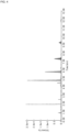
FIG. 2 is a chart illustrating the dialkyl polysulfide (A) obtained in Example 1 and peaks corresponding to the dialkyl polysulfides of each n value (n = 3 to 8). -
FIG. 3 is a chart illustrating the dialkyl polysulfide (A) obtained in Example 41 and peaks corresponding to the dialkyl polysulfides of each n value (n = 3 to 8). -
FIG. 4 is a chart illustrating the dialkyl polysulfide (A) obtained in Example 42 and peaks corresponding to the dialkyl polysulfides of each n value (n = 3 to 8). -
FIG. 5 is a graph illustrating a relation between a reaction time and a conversion ratio in the case where a hydrogen pressure is set to 5.0 MPa in Examples. -
FIG. 6 is a graph illustrating a relation between the reaction time and a total yield in the case where the hydrogen pressure is set to 5.0 MPa in Examples. -
FIG. 7 is a graph illustrating a relation between the reaction time and the conversion ratio in the case where the hydrogen pressure is set to 3.0 MPa in Examples. -
FIG. 8 is a graph illustrating a relation between the reaction time and the total yield in the case where the hydrogen pressure is set to 3.0 MPa in Examples. Description of Embodiments - The method for producing sulfurized olefin according to the present invention is a method for producing sulfurized olefin, the method including reacting an olefin compound (a) represented
by R1R2C=CHR3 ··· (1)
(in the formula, R1 and R2 each are alkyl groups; R3 is a hydrogen atom or an alkyl group, and the total number of carbon atoms of R1, R2, and R3 is 2 to 20) with sulfur in the presence of hydrogen to give dialkyl polysulfide (A). - The olefin compound (a) used in the above step has the structure represented by the general formula (1) as described above. From the viewpoint that the compound is easily available and can be preferably used as an extreme pressure additive due to excellent solubility of the dialkyl polysulfide serving as the final product into base oil, among the olefin compound (a), an olefin compound having a total number of carbon atoms in R1 and R2 of 2 to 18 is preferable and an olefin compound having a total number of carbon atoms in R1 and R2 of 2 to 14 is more preferable.
- In addition, from the viewpoint that the compound is easily available and can be preferably used as the extreme pressure additive due to excellent solubility of the dialkyl polysulfide (A) serving as the final product into a base oil, among the olefin compound (a), an olefin compound having a hydrogen atom as R3 is preferable.
- Therefore, among the olefin compounds (a) having the structure represented by the general formula (1), an olefin compound having a total number of carbon atoms in R1 and R2 of 2 to 18 and a hydrogen atom as R3 is preferable, and an olefin compound having a total number of carbon atoms of R1 and R2 of 2 to 14 and a hydrogen atom as R3 is more preferable.
- Examples of the olefin compound (a) used in the present embodiment include diisobutylene, isobutylene, 3-methylpentene, 4-methylheptene, 5-methylundecene, and 3,6-dimethylhexanedecene. Of these compounds, diisobutylene is preferable because this compound provides dialkyl polysulfide having a high sulfur content and less odor.
- In the production method according to the present embodiment, other olefin compounds other than the olefin compound (a) can be used together with the olefin compound (a) to the extent that the effect of the present invention is not impaired. Examples of such olefin compounds include 1-butene, 1-pentene, 1-hexene, 1-octene, 1-decene, 1-dodecene, 1-tetradecene, 1-hexadecene, 1-octadecene, 1-eicosene, or mixtures thereof.
- Sulfur used in the present embodiment is not particularly limited, and may be in a solid state, for example, in the form of small lumps, flakes, or powders, or in a melted state (liquid). Of these states, sulfur in the melted state is particularly preferable from the viewpoint of ease of a charging operation in large scale production.
- In the above step, from the viewpoint of solubility, a ratio of the olefin compound (a) and sulfur to be used is preferably 1.0 mol to 5.0 mol per 1 mol of the olefin (a) in terms of S element (1.0 molar equivalent to 5.0 molar equivalents in terms of S equivalent and 0.125 molar equivalent to 0.625 molar equivalent in terms of S8), more preferably 1.0 mol to 4.0 mol per 1 mol of the olefin (a) in terms of S element (1.0 molar equivalent to 4.0 molar equivalents in terms of S equivalent and 0.125 molar equivalent to 0.5 molar equivalent in terms of S8), and further preferably 1.5 mol to 3.0 mol per 1 mol of the olefin (a) in terms of S element (1.5 molar equivalents to 3.0 molar equivalents in terms of S equivalent and 0.1875 molar equivalent to 0.375 molar equivalent in terms of S8).
- Hydrogen used in the present embodiment is typically hydrogen gas. Hydrogen gas is more widely distributed and easily obtained as compared to hydrogen sulfide. In addition, although flammable, hydrogen gas is non-toxic and odorless, and thus the handling is easy as compared to the handling of hydrogen sulfide. Hydrogen gas is not limited, and may be, for example, 99.99% or more, 99.999% or more, or 99.9999% or more.
- A method for obtaining hydrogen gas is not particularly limited. Hydrogen gas distributed in the market may be obtained or hydrogen gas may be produced using a reforming method, in which hydrogen is obtained by reacting hydrocarbons such as methane with water vapor, or the electrolysis method, in which hydrogen is obtained by electrolyzing water.
- When the olefin compound (a) is reacted with sulfur in the presence of hydrogen, the pressure of supplied hydrogen is preferably 0.1 MPa or more and 10.0 MPa or less, more preferably 1.0 MPa or more and 6.0 MPa or less, and further preferably 1.0 MPa or more and 4.0 MPa or less. Setting the pressure of the supplied hydrogen to 0.1 MPa or more and 10.0 MPa or less allows the yield of the obtained dialkyl polysulfide (A) to be improved.
- A heating temperature in reacting the olefin compound (a) with sulfur in the presence of hydrogen is preferably 100°C or more and 200°C or less, preferably 100°C or more and 160°C or less, further preferably 100°C or more and 140°C or less, and particularly preferably 120°C or more and 140°C or less. Setting the heating temperature during the reaction to 100°C or more and 200°C or less allows the yield of the obtained dialkyl polysulfide (A) to be improved while the productivity is being improved by accelerating the reaction time.
- In the above step, the olefin compound (a) is reacted with sulfur in the presence of hydrogen to give the dialkyl polysulfide (A). The step is not limited to this step and the olefin compound (a) is reacted with sulfur in the presence of hydrogen and a metal element. Subjecting the olefin compound (a) to the contact reaction with sulfur using metal element as a catalyst in the presence of hydrogen allows the yield of the dialkyl polysulfide (A) to be improved.
- The metal element is preferably one or more metal elements selected from Group 6 to Group 11. Examples of such a metal element include the followings.
- Group 6: Chromium (Cr), Molybdenum (Mo), Tungsten (W)
- Group 7: Manganese (Mn), Technetium (Tc), Rhenium (Re)
- Group 8: Iron (Fe), Ruthenium (Ru), Osmium (Os)
- Group 9: Cobalt (Co), Rhodium (Rh), Iridium (Ir)
- Group 10: Nickel (Ni), Palladium (Pd), Platinum (Pt)
- Group 11: Copper (Cu), Silver (Ag), Gold (Au)
- The metal element is preferably a metal element that constitutes, for example, metal oxides or metal sulfides. In the case where the metal element is, for example, a metal element constituting a metal oxide, the olefin compound (a) is reacted with sulfur in the presence of hydrogen and the metal oxide. In the case where the metal element is a metal element constituting a metal sulfide, the olefin compound (a) is reacted with sulfur in the presence of hydrogen and the metal sulfide. The valence of the metal element constituting the metal oxide or the metal sulfide is not particularly limited and can take various values such as +1 and +2.
- In the case where the metal element is a metal element constituting metal oxides, examples of the metal oxides include, but are not limited to the following compounds.
- Metal oxides of Group 6: CrO3, MoO3, WO3
- Metal oxides of Group 7: Mn2O3, Tc2O7, ReO3
- Metal oxides of Group 8: Fe2O3, RuO2, OsO4
- Metal oxides of Group 9: CoO, Rh2O3, IrO2
- Metal oxides of Group 10: NiO, PdO, PtO2
- Metal oxides of Group 11: CuO, Ag2O, Au2O3
- In the case where the metal element is a metal element constituting metal sulfides, the metal sulfides include, but are not limited to the following compounds.
- Metal sulfides of Group 6: Cr2S3, MoS2, WS2
- Metal sulfides of Group 7: MnS, ReS2
- Metal sulfides of Group 8: FeS, RuS2, OsS2
- Metal sulfides of Group 9: CoS, Rh2S3, IrS2
- Metal sulfides of Group 10: Ni3S2, PdS, PtS
- Metal sulfides of Group 11: CuS, Ag2S, Au2S
- In the case where the metal element is, for example, cobalt (Co), cobalt oxide can be used as the metal oxide and cobalt sulfide as the metal sulfide. In the case where cobalt oxide is used as the metal oxide, the olefin compound (a) is reacted with sulfur in the presence of hydrogen and the cobalt oxide. The cobalt oxide to be used is not particularly limited. Examples of the cobalt oxide include CoO, Co2O3, and Co3O4. In the case where cobalt sulfide is used as the metal sulfide, the olefin compound (a) is reacted with sulfur in the presence of hydrogen and the cobalt sulfide. The cobalt sulfide to be used is not particularly limited. Examples of the cobalt sulfide include CoS, Co9S8, CoS2, and Co3S4. Of these compounds, cobalt oxide, in particular Co3O4 is preferable from the viewpoint of improving the yield of the dialkyl polysulfide (A) .
- The added amount of the metal element relative to the olefin compound (a) is preferably 0.1 mol% or more and 10 mol% or less, more preferably 1.0 mol% or more and 10 mol% or less, and further preferably 2.0 mol% or more and 7.0 mol% or less. The added amount of the metal element relative to the olefin compound (a) of 0.1 mol% or more and 10 mol% or less allows the reaction between the olefin compound (a) and sulfur in the presence of hydrogen to be promoted and the yield of the obtained dialkyl polysulfide (A) to be improved.
- In the above step, the olefin compound (a) is reacted with sulfur in the presence of hydrogen to give the dialkyl polysulfide (A). The step is not limited to this step, and the olefin compound (a) is reacted with sulfur in the presence of hydrogen, the metal element, and zeolite. Using the metal element and zeolite as catalysts and subjecting the olefin compound (a) to the contact reaction with sulfur using the two catalysts in the presence of hydrogen allow the yield of the dialkyl polysulfide (A) to be improved.
- Zeolite is crystalline aluminosilicate, which has a backbone structure of regularly linked silica and alumina, and also contains cations as ion exchange sites in the pore structure. The pore structure defined by the zeolite backbone structure is not particularly limited. Examples of the structure include LTA (type A), FER (ferrierite), MWW (MCM-22), MFI (ZSM-5), MOR (mordenite), LTL (type L), FAU (type Y and type X), and BEA (type beta). Of these types, zeolite having the X-type or A-type pore structure is preferable from the viewpoint of easy availability and economic efficiency.
- The zeolite preferably has basicity. Examples of the zeolite having basicity include zeolite containing alkali metal or alkaline earth metal cations. Examples of the alkali metal include sodium (Na) and potassium (K), and examples of the alkaline earth metal include magnesium (Mg) and calcium (Ca).
- From the viewpoint of improving the yield of the dialkyl polysulfide (A), the zeolite is preferably the Na-X type zeolite, which has an X-type backbone structure and contains sodium ions, or the Na-A type zeolite, which has an A-type backbone structure and contains sodium ions. Of these zeolites, the Na-X type zeolite is more preferable.
- The added amount of zeolite is preferably 2.0 parts by mass or more and 25 parts by mass or less, more preferably 2.0 parts by mass or more and 15 parts by mass or less, further preferably 3.0 parts by mass or more and 10 parts by mass or less, and particularly preferably 4.0 parts by mass or more and 8.0 parts by mass or less relative to 100 parts by mass of the olefin compound (a). The added amount of zeolite of 2.0 parts by mass or more and 25 parts by mass or less relative to 100 parts by mass of the olefin compound (a) allows the yield of the obtained dialkyl polysulfide (A) to be further improved.
- The dialkyl polysulfide (A) obtained by the production method according to the present embodiment is a mixture of dialkyl polysulfides having different numbers of sulfur atoms. The content (yield) of each of the dialkyl polysulfides having different numbers of sulfur atoms can be determined by the peak areas of the chart obtained by ultra high-performance liquid chromatography (hereinafter also referred to as "UPLC") measurement. The total yield of the dialkyl polysulfides (A) can be determined from the total of each yield of the dialkyl polysulfides having different numbers of sulfur atoms.
- In the case of applications in which sulfurization of passive coating films for difficult-to-process metals or other materials is desired to be promoted, the amount of active sulfur in the dialkyl polysulfide (A) obtained by the production method according to the present embodiment is 20% by mass to 50% by mass and more preferably 30% by mass to 45% by mass relative to the total sulfur content as the standard. From the viewpoint of effectively forming a metal sulfide film on a metal surface and being less likely to cause the corrosion of the metal surface, the amount of the active sulfur is preferably 0.1% by mass to 30% by mass and more preferably 0.5% by mass to 20% by mass relative to the total sulfur content as the standard. The amount of the active sulfur in the present invention is determined by the method specified in ASTM-D1662.
- The dialkyl polysulfide (A) (sulfurized olefin) obtained by the production method according to the present embodiment is represented by the following general formula (2) .


- (In the formula, R1 and R2 each are alkyl groups; R3 is a hydrogen atom or an alkyl group; the total number of carbon atoms of one R1, one R2, and one R3 is 2 to 20; and n is an integer of 1 to 8.)
- In the general formula (2), from the viewpoint that the dialkyl polysulfide (A) has excellent solubility in a base oil and can be preferably used as an extreme pressure additive, the total number of carbon atoms of R1 and R2 is preferably 2 to 18, and the total number of carbon atoms of R1 and R2 is more preferably 2 to 14.
- In the general formula (2), from the viewpoint that the dialkyl polysulfide (A) has excellent solubility in a base oil and can be preferably used as an extreme pressure additive, R3 is preferably a hydrogen atom.
- Therefore, in the general formula (2), it is preferable that the total number of carbon atoms of R1 and R2 be 2 to 18 and R3 be a hydrogen atom and it is more preferable that the total number of carbon atoms of R1 and R2 be 2 to 14 and R3 be a hydrogen atom.
- From the viewpoint that the dialkyl polysulfide (A) effectively forms a metal sulfide film on a metal surface, is less likely to cause corrosion of the metal surface, and can be suitably used as an extreme pressure additive, n is preferably an integer of 2 to 8 and more preferably an integer of 3 to 8.
- In the method for producing sulfurized olefin according to the present embodiment, the dialkyl polysulfide (A) may be obtained by reacting the olefin compound (a) represented by
R1R2C=CHR3 ··· (1)
(in the formula, R1 and R2 each are an alkyl group; R3 is a hydrogen atom or an alkyl group; and the total number of carbon atoms of R1, R2, and R3 is 2 to 20) with sulfur in the presence of hydrogen and a radical scavenger. The radical scavenger is not particularly limited as long as the radical scavenger has radical scavenging ability. Examples of the radical scavenger include 2,6-di-tert-butyl-p-cresol. The reaction between the olefin compound (a) represented by the general formula (1) and sulfur proceeds even in the presence of the radical scavenger, and thus it is assumed that the reaction is not a radical reaction because the influence of the radical scavenger is small. Therefore, the dialkyl polysulfide (A) can also be obtained in this production method. - The production method according to the present embodiment allows the metal sulfide film to be effectively formed on the metal surface and the dialkyl polysulfide (A), which can be suitably used as an extreme pressure additive, to be efficiently obtained. The obtained dialkyl polysulfide (A) effectively forms the metal sulfide film on the metal surface and can be suitably used as the extreme pressure additive.
- The extreme pressure additive may be formed of the dialkyl polysulfide (A) alone or may include dialkyl polysulfide (B) other than the dialkyl polysulfide (A). The dialkyl polysulfide (B) is represented, for example, by the following general formula (3).


- In the general formula (3), examples of R4 and R5 include linear alkyl groups and branched alkyl groups. Examples of the linear alkyl groups include a methyl group, an ethyl group, a n-butyl group, a n-pentyl group, a n-octyl group, a n-decyl group, a n-dodecyl group, a n-hexadecyl group, and a n-octadecyl group. Examples of the branched alkyl groups include a 3-methylpentyl group, a 4-methylheptyl group, a 5-methylundecyl group, and a 3,6-dimethylhexanedecyl group.
- Of the dialkyl polysulfides (B), the total number of carbon atoms of one R4 and one R5 is preferably 4 to 16 and more preferably 4 to 10 from the viewpoint that a high sulfur content can be maintained and the excellent metal sulfide film can be formed on the metal surface.
- In the case of applications in which sulfurization of passive coating films for difficult-to-process metals or other materials is desired to be promoted, the amount of the active sulfur in the dialkyl polysulfide (B) is preferably 20% by mass to 50% by mass and more preferably 30% by mass to 45% by mass relative to the total sulfur content as the standard. From the viewpoint of effectively forming the metal sulfide film on the metal surface and being less likely to cause corrosion of the metal surface, the amount of the active sulfur is preferably 0.1% by mass to 30% by mass and more preferably 0.5% by mass to 20% by mass relative to the total sulfur content as the standard. The amount of the active sulfur in the dialkyl polysulfide (B) is determined by the method specified in ASTM-D1662.
- The dialkyl polysulfide (B) is obtained by reacting an olefin compound (b) represented by
R4HC=CHR5 ··· (4)
(in the formula, R4 and R5 each are a hydrogen atom or an alkyl group, and the total number of carbon atoms of R4 and R5 is 4 to 20) with sulfur in the presence of hydrogen. - The olefin compound (b) used in the production method has the structure represented by the general formula (4), as described above. Of the dialkyl polysulfides (B), an olefin compound having the total number of carbon atoms of R4 and R5 of 4 to 16 is preferably used and an olefin compound having the total number of carbon atoms of R4 and R5 of 4 to 10 is more preferably used as the olefin compound (b) from the viewpoint that a high sulfur content can be maintained and the excellent metal sulfide film can be formed on the metal surface. In addition, an olefin compound having an alkyl group having a number of carbon atoms of 4 to 16 as R4 and a hydrogen atom as R5 is preferably used and an olefin compound having an alkyl group having a number of carbon atoms of 4 to 10 as R4 and a hydrogen atom as R5 is more preferably used as the olefin compound (b) from the viewpoint that the reactivity is excellent and the dialkyl polysulfide (B) is efficiently obtained.
- Examples of the olefin compound (b) include linear 1-olefin and branched 1-olefin having a branched structure other than the ends. Examples of the linear 1-olefin include 1-butene, 1-pentene, 1-hexene, 1-octene, 1-decene, 1-dodecene, 1-tetradecene, 1-hexadecene, 1-octadecene, 1-eicosene, or mixtures thereof.
- Of the olefin compounds (b), the linear 1-olefin is preferable because the linear 1-olefin is industrially readily available and reaction of the linear 1-olefin with sulfur proceeds easily. Of the linear 1-olefins, olefin compounds having a number of carbon atoms of 6 to 18 are preferable because these olefin compounds have a low flow point and thus can maintain a liquid state at room temperature. Of these olefin compounds, olefin compounds having a number of carbon atoms of 6 to 12 are more preferable.
- As sulfur and hydrogen, the same sulfur and hydrogen used in the production method described above may be used.
- A lubricating fluid composition can include the extreme pressure additive obtained in the present embodiment and a base oil. The base oil is not particularly limited and can be used by appropriately selecting from mineral oils, synthetic oils, and other oils depending on the purpose of use, conditions of use, and other factors. Examples of the mineral oils include distillate oils obtained by atmospheric distillation of paraffinic oils, intermediate oils, and naphthenic oils or by reduced pressure distillation of residues after atmospheric distillation, or refined oils obtained by refining these oils by solvent refining, hydrogenated refining, wax removal treatment, white earth treatment, or other refining processes. Examples of the synthetic oils include low molecular weight polybutene, low molecular weight polypropylene, α-olefin oligomers having a number of carbon atoms of 8 to 14 and hydrogenated products thereof, polyol esters such as fatty acid esters of trimethylolpropane and fatty acid esters pentaerythritol, ester-based compounds such as dibasic acid esters, aromatic polycarboxylic acid esters, and phosphate esters, alkyl aromatic compounds such as alkyl benzenes and alkyl naphthalenes, polyglycol oils such as polyalkylene glycols, and silicone oils. These oils may be appropriately used alone or in combination of two or more of the oils.
- The blend ratio of the extreme pressure additive to the base oil in the lubricating fluid composition is not particularly limited. Usually, the blend ration is 0.01 part by mass to 50 parts by mass and preferably 0.05 part by mass to 20 parts by mass per 100 parts by mass in terms of dialkyl polysulfide in the extreme pressure additive relative to the base oil.
- The lubricating fluid composition can also be used as grease by further adding a thickener to the lubricating fluid composition. Examples of the thickener that can be used here include soap-based products such as metallic soap-based products and composite soap-based products, or urea-based products. In the case where these thickeners are used, the thickeners may be previously mixed in the base oil to homogenize the mixture.
- The lubricating fluid composition may include additives in addition to the extreme pressure additive and the base oil. For example, additives such as oiliness agents, wear-resistant agents, extreme pressure agents, other rust inhibitors, corrosion inhibitors, antifoam agents, cleaning dispersants, flow point depressants, viscosity index improvers, antioxidants, emulsifiers, antiemulsifiers, mold inhibitors, friction modifiers, and surfactants can be used together depending on the target application and performance.
- Specific examples of various types of the additives may be exemplified as follows. Examples of the oiliness agents include long-chain fatty acids (oleic acid); examples of the wear-resistant agents include phosphate esters and metal dithiophosphate salts; examples of the extreme pressure agents include organosulfur compounds and organohalogen compounds; examples of other rust inhibitors include carboxylic acids, amines, alcohols, and esters; examples of the corrosion inhibitors include nitrogen compounds (such as benzotriazole) and compounds containing sulfur and nitrogen (1,3,4-thiadiazolyl-2,5-bis-dialkyl dithiocarbamate); examples of the antifoam agents include silicone oils, metal soaps, fatty acid esters, and phosphate esters; examples of the cleaning dispersants include neutral and basic sulfonate and phenates (metal salt type), succinimide, esters, and benzylamine copolymer polymers; examples of the flow point depressants include condensation products of chlorinated paraffins with naphthalene or phenol, polyalkylacrylates and methacrylates, polybutene, polyalkylstyrene, and polyvinyl acetate; examples of the viscosity index improvers include polymethacrylates, polyisobutylene, olefin copolymers, and polyalkylstyrene; examples of the antioxidants include amines, hindered phenols, zinc thiophosphate, and trialkyl phenols; examples of the emulsifiers include esters of sulfuric acid, sulfonic acid, and phosphoric acid, fatty acid derivatives, amine derivatives, quaternary ammonium salts, and polyoxyethylene-based activators; examples of the antiemulsifiers include quaternary ammonium salts, sulfated oils, and phosphate esters; and examples of the mold inhibitors include phenolic compounds, formaldehyde donor compounds, and salicylanilide-based compounds.
- The lubricating fluid composition is a composition in which the extreme pressure additive, the base oil, and if necessary, the thickener and other additives are homogeneously blended. The blending method is not particularly limited. At this time, the mixture can be heated to 30°C to 60°C for homogenization.
- The applications of the lubricating fluid composition are not particularly limited. For example, the lubricating fluid composition can be used as the lubricant composition and can be used as lubricant oils for automobiles used in internal combustion engines, automatic transmissions, buffers, drive system components such as power steering, and gears; metalworking oils used in cutting processes, grinding processes, plastic forming processes, and other metalworking processes; and hydraulic oils serving as power transmission fluids used for operations in power transmission, power control and buffers for hydraulic systems such as hydraulic equipment and devices. In particular, the lubricating fluid composition according to the present invention can reduce the degree of swelling to the sealant (chloroprene rubber, nitrile rubber, and the like) of a gearbox used when the lubricating fluid composition is used as a gear oil as compared to conventional products. Consequently, the lubricating fluid composition can be suitably used for applications in which the lubricating fluid composition is brought into contact with the sealant.
- Hereinafter, Examples of the present invention will be described. The present invention, however, is not limited to Examples described below.
- A stirrer, 20 mmol of diisobutylene (2,4,4-trimethyl-1-pentene), 0.1875 molar equivalent of powdered sulfur (S8) (1.5 molar equivalents as S element), and 5 mol% of Co3O4 (manufactured by Sigma-Aldrich Co. LLC, nano powder: 50 nm or less (TEM)) were charged into an autoclave, and thereafter hydrogen was charged by pressurizing to 3.0 MPa. The autoclave was heated to 130°C while the resultant mixture was being stirred at 800 rpm using a magnetic stirrer, and a reaction was performed at the same temperature for 20 hours. Thereafter, the autoclave was cooled to room temperature and a pressure valve was opened. Thereafter, 200 mg of 1,3,5-tri-tert-butylbenzene as an internal standard (8.91 parts by mass relative to 100 parts by mass of diisobutylene) was added to the reaction solution. Further, air was blown into the autoclave to remove residual hydrogen sulfide. After removing unreacted sulfur and Co3O4 by a centrifugal separator, dialkyl polysulfide (A) was obtained. The reaction in the production method of the dialkyl polysulfide in Example 1 is illustrated in
FIG. 1 . - Dialkyl polysulfide (A) was obtained in the same manner as the manner in Example 1 except that the type of the metal catalyst was changed from Co3O4 to Co3S4. Co3S4 was obtained by adjusting according to a literature "Liu, Q.; Zhang, J. CrystEngComm, 2013, 15, 5087".
- Dialkyl polysulfide (A) was obtained in the same manner as the manner in Example 1 except that the type of the metal catalyst was changed from Co3O4 to Ag2O (manufactured by Wako Pure Chemical Corporation, Special Grade, Catalog Number 199-00882) .
- Dialkyl polysulfide (A) was obtained in the same manner as the manner in Example 1 except that the type of the metal catalyst was changed from Co3O4 to MoO3 (manufactured by Wako Pure Chemical Corporation, First Grade, Catalog Number 138-03352) .
- Dialkyl polysulfide (A) was obtained in the same manner as the manner in Example 1 except that the type of the metal catalyst was changed from Co3O4 to CuO (manufactured by Kanto Chemical Co., Inc., Special Grade, Catalog Number 07503-30).
- Dialkyl polysulfide (A) was obtained in the same manner as the manner in Example 1 except that the type of the metal catalyst was changed from Co3O4 to NiO (manufactured by Wako Pure Chemical Corporation, Catalog Number 140-01552, 99% or higher).
- Dialkyl polysulfide (A) was obtained in the same manner as the manner in Example 1 except that the type of the metal catalyst was changed from Co3O4 to Fe2O3 (manufactured by Wako Pure Chemical Corporation, First Grade, Catalog Number 096-04825).
- Dialkyl polysulfide (A) was obtained in the same manner as the manner in Example 1 except that the type of the metal catalyst was changed from Co3O4 to CuS (manufactured by FUJIFILM Wako Pure Chemical Corporation, Catalog Number 034-04462, 90% or more).
- Dialkyl polysulfide (A) was obtained in the same manner as the manner in Example 1 except that the type of the metal catalyst was changed from Co3O4 to MoS2 (manufactured by Kanto Chemical Co., Inc., Catalog No. 25368-32, 98% or more).
- The dialkyl polysulfides (A) obtained in Examples 1 to 9 were measured and evaluated by the following methods.
- An ultra-high performance liquid chromatograph (manufactured by Waters Corporation, ACQUITY UPLC H-Class system) was used to obtain a chart of the dialkyl polysulfide (A) under the following measurement conditions. The yield (%) of each of the dialkyl polysulfides (n = 2 to 8) having different numbers of sulfur atoms was calculated by the ratio of the peak areas corresponding to the dialkyl polysulfides of each n value, using 1,3,5-tri-tert-butylbenzene as an internal standard. The total yield of the dialkyl polysulfide (A) was determined to be the total of the yield of each of the dialkyl polysulfides having different numbers of sulfur atoms. The conversion ratio was calculated from the yield of diisobutylene. The yields of thiol and diisobutylene were calculated from the results of 1H NMR measurements of the sample of the recovered reaction solution diluted with CDCl3 solvent using a FT-NMR apparatus (manufactured by JEOL Ltd., JNM-ECA600). In this measurement, 1,3,5-tri-tert-butylbenzene was also used as the internal standard.
-
- Eluent: H2O/MeCN/iPrOH = 25/25/50, Flow rate: 0.5 mL/min, Column: kinetex-C8, 2.6 um, 150 mm × 2.1 mm
- Detector: PDA
- Detection wavelength: 210 nm to 800 nm
- [NMR Measurement Conditions]
- 1H-NMR: 600 MHz
- As an example, the chart of the dialkyl polysulfide (A) obtained in Example 1 and the peaks corresponding to the dialkyl polysulfides of each n value (n = 3 to 8) are illustrated in
FIG. 2 . - The measurement and evaluation results of Examples 1 to 9 are listed in Table 1. "N.D. (not determined)" in Table 1 indicates that the yield was not able to be calculated because the target peak was covered with other peaks.
[Table 1] Experimental number Catalyst Catalyst amount (mol%) Na-X (mg) Hydroge n pressur e (MPa) S equ iva len t Tern per atu re (°C) Tim e (h) Con ver sio n rat io RSH yie ld RS2R yie ld RS3R yiel d RS4R yie ld RS5R yie ld RSsR yie ld RS7R yie ld RS8R yie ld RSnR tot al yie ld Example 3 Ag2O 5 - 3.0 1.5 130 20 56 0 0 N.D. 3 3 1 0 0 7 Example 4 MoO3 5 - 3.0 1.5 130 20 82 0 0 N.D. 2 5 1 0 0 8 Example 5 CuO 5 - 3.0 1.5 130 20 72 0 0 N.D. 5 5 1 0 0 12 Example 6 NiO 5 - 3.0 1.5 130 20 62 1 0 N.D. 5 10 3 1 0 19 Example 7 Fe2O3 5 - 3.0 1.5 130 20 60 0 0 N.D. 14 7 2 1 0 24 Example 1 Co3O9 5 - 3.0 1.5 130 20 83 2 0 11 29 9 3 1 0 53 Example 2 Co3S9 5 - 3.0 1.5 130 20 82 0 0 13 30 10 3 1 0 57 Example 8 CuS 5 - 3.0 1.5 130 20 53 0 0 0 3 2 1 0 0 6 Example 9 MoS2 5 - 3.0 1.5 130 20 50 0 0 0 3 2 1 0 0 6 - From the results listed in Table 1, it was found that in any of Examples 1 to 9, the reaction of diisobutylene with powdered sulfur in the presence of hydrogen and any one of Co3O4, Co3S4, Ag2O, MoO3, CuO, NiO, Fe2O3, CuS, and MoS2 gave the dialkyl polysulfides (A) having total yields of 6% to 57%. In particular, it was found that in Examples 1 and 2, the reaction of diisobutylene with sulfur in the presence of hydrogen and cobalt oxide or cobalt sulfide using Co as the metal element allowed the total yield of the dialkyl polysulfides (A) (n = 2 to 8) to be more than 50%.
- A stirrer, 20 mmol of diisobutylene, 0.375 molar equivalent of powdered sulfur (S8) (3.0 molar equivalents as S element), 2.5 mol% of CoS2, and 100 mg of zeolite (manufactured by NACALAI TESQUE, INC., Na-X type, a fine product formed by crushing molecular sieve 13X and sieving to a particle diameter of 125 um or less) (4.45 parts by mass relative to 100 parts by mass of diisobutylene) were charged into an autoclave, and thereafter hydrogen was charged by pressurizing to 3.0 MPa. The autoclave was heated to 130°C while the resultant mixture was being stirred at 800 rpm using a magnetic stirrer, and a reaction was performed at the same temperature for 20 hours. Thereafter, the autoclave was cooled to room temperature and a pressure valve was opened. Thereafter, 200 mg of 1,3,5-tri-tert-butylbenzene as an internal standard (8.91 parts by mass relative to 100 parts by mass of diisobutylene) was added to the reaction solution. Further, air was blown into the autoclave to remove residual hydrogen sulfide. After removing unreacted sulfur, CoS2, and zeolite by a centrifugal separator, dialkyl polysulfide (A) was obtained.
- Dialkyl polysulfide (A) was obtained in the same manner as the manner in Example 10 except that the type of the metal catalyst was changed from CoS2 to Co3S4. As Co3S4, the same Co3S4 used in Example 2 was used.
- Dialkyl polysulfide (A) was obtained in the same manner as the manner in Example 10 except that the type of the metal catalyst was changed from CoS2 to CoS (manufactured by Strem Chemicals, Inc.).
- Dialkyl polysulfide (A) was obtained in the same manner as the manner in Example 10 except that the type of the metal catalyst was changed from CoS2 to Co3O4 (manufactured by Sigma-Aldrich Co. LLC, nano powder: 50 nm or less (TEM)). The measurement and evaluation results of Examples 10 to 13 are listed in Table 2.
[Table 2] Experimental number Catalyst Catalyst amount (mol%) Na-X (mg) Hydroge n pressur e (MPa) S equ iva len t Tern per atu re (°C) Tim e (h) Con ver sio n rat io RSH yie ld RS2R yie ld RS3R yiel d RS4R yie ld RS5R yie ld RS6R yie ld RS7R yie ld RS8R yie ld RSnR tot al yie ld Example 12 CoS 2.5 100 3.0 3 130 20 51 0 0 N.D. 8 7 2 0 0 17 Example 10 CoS2 2.5 100 3.0 3 130 20 97 1 0 12 41 19 7 2 1 82 Example 11 Co3S4 2.5 100 3.0 3 130 20 96 1 0 12 39 21 8 2 1 83 Example 13 Co3O4 2.5 100 3.0 3 130 20 90 1 1 8 22 24 8 2 1 64 - From the results listed in Table 2, it was found that in any of Examples 10 to 13, the reaction of diisobutylene with powdered sulfur in the presence of hydrogen and any one of CoS, CoS2, Co3S4, and Co3O4 gave the dialkyl polysulfides (A) in total yields of 17% to 83%. In particular, it was found that in Examples 10 and 11, the reaction of diisobutylene with sulfur in the presence of hydrogen, either CoS2 (cobalt disulfide) or Co3S4 (tricobalt tetrasulfide), and the zeolite allowed the total yield of the dialkyl polysulfides (A) (n = 2 to 8) to be more than 80%. It was also found that in Example 11, the use of zeolite in addition to Co3S4 allowed the yield of the dialkyl polysulfide (A) to be improved as compared to the yield in Example 2.
- Dialkyl polysulfide (A) was obtained in the same manner as the manner in Example 10 except that the charged amount of the zeolite (manufactured by NACALAI TESQUE, INC., Na-X type, a fine product formed by crushing molecular sieve 13X and sieving to a particle diameter of 125 um or less) was changed from 100 mg to 50 mg (2.23 parts by mass relative to 100 parts by mass of diisobutylene).
- Dialkyl polysulfide (A) was obtained in the same manner as the manner in Example 10 except that the charged amount of the zeolite (manufactured by NACALAI TESQUE, INC., Na-X type, a fine product formed by crushing molecular sieve 13X and sieving to a particle diameter of 125 um or less) was changed from 100 mg to 200 mg (8.91 parts by mass relative to 100 parts by mass of diisobutylene). The measurement and evaluation results of Examples 14 and 15 and Example 10 as a reference are listed in Table 3.
[Table 3] Experimental number Catalyst Catalyst amount (mol%) Na-X (mg) Hydroge n pressur e (MPa) S equ iva len t Tern per atu re (°C) Tim e (h) Con ver sio n rat io RSH yie ld RS2R yie ld RS3R yiel d RS4R yie ld RS5R yie ld RS6R yie ld RS7R yie ld RS8R yie ld RSnR tot al yie ld Example 10 CoS2 2.5 100 3.0 3 130 20 97 1 0 12 41 19 7 2 1 82 Example 14 CoS2 2.5 50 3.0 3 130 20 71 0 0 8 11 11 3 1 0 34 Example 15 CoS2 2.5 200 3.0 3 130 20 96 0 0 9 34 18 7 2 1 70 - From the results listed in Table 3, it was found that in both Example 14 and Example 15, the total yields of the dialkyl polysulfides (A) (n = 2 to 8) were more than 34%.
- It was also found that when the charged amount of the zeolite was increased, the total yield of the dialkyl polysulfides (A) (n = 2 to 8) was increased and when the charged amount of the zeolite exceeded a certain amount, the total yield of the dialkyl polysulfides (A) (n = 2 to 8) tended to gradually decrease.
- Dialkyl polysulfide (A) was obtained in the same manner as the manner in Example 10 except that the heating temperature of the autoclave, that is, a reaction temperature was changed from 130°C to 115°C.
- Dialkyl polysulfide (A) was obtained in the same manner as the manner in Example 10 except that the heating temperature of the autoclave, that is, a reaction temperature was changed from 130°C to 115°C. The measurement and evaluation results of Examples 16 and 17 and Example 10 as a reference are listed in Table 4.
[Table 4] Experimental number Catalyst Catalyst amount (mol%) Na-X (mg) Hydroge n pressur e (MPa) S equ iva len t Tern per atu re (°C) Tim e (h) Con ver sio n rat io RSH yie ld RS2R yie ld RS3R yiel d RS4R yie ld RS5R yie ld RS6R yie ld RS7R yie ld RS8R yie ld RSnR tot al yie ld Example 10 CoS2 2.5 100 3.0 3 130 20 97 1 0 12 41 19 7 2 1 82 Example 16 CoS2 2.5 100 3.0 3 115 20 31 0 0 2 4 3 1 0 0 10 Example 17 CoS2 2.5 100 3.0 3 150 20 94 2 0 6 25 11 4 1 0 47 - From the results listed in Table 4, it was found that in both Examples 16 and 17, the total yields of the dialkyl polysulfides (A) (n = 2 to 8) were more than 10%.
- It was also found that in the range of the reaction temperature of 100°C to 160°C, when the reaction temperature became higher, the total yield of the dialkyl polysulfides (A) (n = 2 to 8) was increased and when the reaction temperature exceeded a certain value, the total yield of the dialkyl polysulfides (A) (n = 2 to 8) tended to gradually decrease.
- A stirrer, 10 mmol of diisobutylene, 0.375 molar equivalent of powdered sulfur (S8) (3.0 molar equivalents as S element), 2.5 mol% of CoS2, and 50 mg of zeolite (manufactured by NACALAI TESQUE, INC., Na-X type, a fine product formed by crushing molecular sieve 13X and sieving to a particle diameter of 125 um or less) (4.45 parts by mass relative to 100 parts by mass of diisobutylene) were charged into an autoclave, and thereafter hydrogen was charged by pressurizing to 0.7 MPa. The autoclave was heated to 130°C while the resultant mixture was being stirred at 800 rpm using a magnetic stirrer, and a reaction was performed at the same temperature for 20 hours. Thereafter, the autoclave was cooled to room temperature and a pressure valve was opened. Thereafter, 100 mg of 1,3,5-tri-tert-butylbenzene as an internal standard (8.91 parts by mass relative to 100 parts by mass of diisobutylene) was added to the reaction solution. Further, air was blown into the autoclave to remove residual hydrogen sulfide. After removing unreacted sulfur, CoS2, and zeolite by a centrifugal separator, dialkyl polysulfide (A) was obtained. Here, in this Example, due to the significant change in experimental conditions by a decrease in the pressure of hydrogen, the charged amount of the zeolite (Na-X) in this Example was set to 50 mg (1/2 scale) to perform the reaction.
- Dialkyl polysulfide (A) was obtained in the same manner as the manner in Example 10 except that the hydrogen pressure during the charge was changed from 3.0 MPa to 5.0 MPa. The measurement and evaluation results of Examples 18 and 19 and Example 10 as a reference were listed in Table 5.
[Table 5] Experimental number Catalyst Catalyst amount (mol%) Na-X (mg) Hydroge n pressur e (MPa) S equ iva len t Tern per atu re (°C) Tim e (h) Con ver sio n rat io RSH yie ld RS2R yie ld RS3R yiel d RS4R yie ld RS5R yie ld RS6R yie ld RS7R yie ld RS8R yie ld RSnR tot al yie ld Example 10 CoS2 2.5 100 3.0 3 130 20 97 1 0 12 41 19 7 2 1 82 Example 18 CoS2 2.5 50 0.7 3 130 20 69 0 0 6 9 7 2 1 0 25 Example 19 CoS2 2.5 100 5.0 3 130 20 93 0 0 9 22 30 10 3 1 75 - From the results listed in Table 5, it was found that in both Example 18 and Example 19, the total yields of the dialkyl polysulfides (A) (n = 2 to 8) were more than 25%.
- It was also found that in the range of the hydrogen pressure of 1.0 MPa to 6.0 MPa, when the hydrogen pressure became higher, the total yield of the dialkyl polysulfides (A) (n = 2 to 8) was increased and when the hydrogen pressure exceeded a certain value, the total yield of the dialkyl polysulfides (A) (n = 2 to 8) tended to gradually decrease.
- Dialkyl polysulfide (A) was obtained in the same manner as the manner in Example 10 except that the type of zeolite was changed to Na-X type (beads, Na-X type used in Example 10, an uncrushed product of molecular sieve 13X, grain diameter: about 2 mm).
- Dialkyl polysulfide (A) was obtained in the same manner as the manner in Example 10 except that the type of zeolite was changed from Na-X type to Na-A type (manufactured by Wako Pure Chemical Corporation, catalog number 137-06085,
molecular sieve 4A 1/16 was crushed and sieved to a particle diameter of 125 um or less). - Dialkyl polysulfide (A) was obtained in the same manner as the manner in Example 10 except that the type of zeolite was changed from Na-X type to K-A type (manufactured by Wako Pure Chemical Corporation, catalog number 134-06095,
molecular sieve 3A 1/16 was crushed and sieved to a particle diameter of 125 um or less). The measurement and evaluation results of Examples 20 and 22 and Example 10 as a reference were listed in Table 6.[Table 6] Experimental number Catalyst Catalys t amount (mol%) Zeolite (100 mg) Hydr ogen pres sure (MPa ) S equ iva len t Tern per atu re (°C ) Tim e (h) Con ver sio n rat io RSH yie ld RS2R yie ld RS3R yiel d RS4R yie ld RS5R yie ld RS6R yie ld RS7R yie ld RS8R yie ld RSnR tot al yie ld Example 10 CoS2 2.5 Na- X 3 3 130 20 97 1 0 12 41 19 7 2 1 82 Example 20 CoS2 2.5 Na-X (Beads) 3 3 130 20 72 0 0 9 6 9 3 1 0 28 Example 21 CoS2 2.5 Na- A 3 3 130 20 76 0 0 8 9 9 3 1 0 30 Example 22 CoS2 2.5 K-A 3 3 130 20 83 0 0 8 20 13 4 1 0 46 - From the results listed in Table 6, it was found that in any of Examples 20 to 22, the total yields of the dialkyl polysulfides (A) (n = 2 to 8) were more than 28%.
- It was found that when the Na-X type and the Na-A type having the same cation and different pore structures were compared, the total yield of the dialkyl polysulfides (A) (n = 2 to 8) when the zeolite having a pore structure of the X type was used was higher than the total yield when the zeolite having a pore structure of the A type. It was also found that among the Na-X types, the total yield of the dialkyl polysulfides (A) (n = 2 to 8) was higher when the Na-X type having a smaller particle diameter by crashing was used. Furthermore, when the Na-A type was compared to the K-A type having the same pore structure and different cations, it was found that the total yield of the dialkyl polysulfides (A) (n = 2 to 8) was higher when the cation was K ion than the total yield when the cation was Na ion.
- A stirrer, 20 mmol of diisobutylene, and 0.1875 molar equivalent of powdered sulfur (S8) (1.5 molar equivalents as S element) were charged into an autoclave, and thereafter hydrogen was charged by pressurizing to 3.0 MPa. The autoclave was heated to 130°C while the resultant mixture was being stirred at 800 rpm using a magnetic stirrer, and a reaction was performed at the same temperature for 20 hours. Thereafter, the autoclave was cooled to room temperature and a pressure valve was opened. Thereafter, 200 mg of 1,3,5-tri-tert-butylbenzene as an internal standard (8.91 parts by mass relative to 100 parts by mass of diisobutylene) was added to the reaction solution. Further, air was blown into the autoclave to remove residual hydrogen sulfide. After removing unreacted sulfur by a centrifugal separator, dialkyl polysulfide (A) was obtained.
- A stirrer, 20 mmol of diisobutylene, 0.1875 molar equivalent of powdered sulfur (S8) (1.5 molar equivalents as S element), and 100 mg of zeolite (manufactured by NACALAI TESQUE, INC., Na-X type, a fine product formed by crushing molecular sieve 13X and sieving to a particle diameter of 125 um or less) were charged into an autoclave, and thereafter hydrogen was charged by pressurizing to 3.0 MPa. The autoclave was heated to 130°C while the resultant mixture was being stirred at 800 rpm using a magnetic stirrer, and a reaction was performed at the same temperature for 20 hours. Thereafter, the autoclave was cooled to room temperature and a pressure valve was opened. Thereafter, 200 mg of 1,3,5-tri-tert-butylbenzene as an internal standard (8.91 parts by mass relative to 100 parts by mass of diisobutylene) was added to the reaction solution. Further, air was blown into the autoclave to remove residual hydrogen sulfide. After removing unreacted sulfur and the zeolite by a centrifugal separator, dialkyl polysulfide (A) was obtained. The measurement and evaluation results of Examples 23 and 24 and Example 1 as a reference were listed in Table 7.
[Table 7] Experimental number Catalyst Catalyst amount (mol%) Na-X (mg) Hydroge n pressur e (MPa) S equ iva len t Tern per atu re (°C ) Tim e (h) Con ver sio n rat io RSH yie ld RS2R yie ld RS3R yiel d RS4R yie ld RS5R yie ld RS6R yie ld RS7R yie ld RS8R yie ld RSnR tot al yie ld Example 1 Co3O4 5 - 3.0 1.5 130 20 83 2 0 11 29 9 3 1 0 53 Example 23 - - - 3.0 1.5 130 20 57 0 0 3 8 2 1 0 0 14 Example 24 - - 100 3.0 1.5 130 20 35 0 0 4 2 4 1 0 0 11 - From the results in Table 7, it was found that in Example 23, the reaction of diisobutylene with powdered sulfur in the presence of hydrogen gave dialkyl polysulfide (A) in a total yield of 14%. In addition, it was found that, in Example 24, the reaction of diisobutylene with powdered sulfur in the presence of hydrogen and zeolite gave dialkyl polysulfide (A) in a total yield of 11%.
- Into a 1-liter autoclave equipped with a heating device, hydrogen sulfide blowpipe, and hydrogen sulfide absorption equipment, 365 g (3.26 mol) of diisobutylene, 104 g (3.26 mol) of powdered sulfur, 0.1 g of potassium hydroxide, and 4 g of butylcarbitol were charged. The autoclave was tightly closed, and thereafter a pressure in the reaction container was reduced to -0.1 MPa or less using a vacuum pump to perform vacuum degassing. Thereafter, the autoclave was tightly closed and thereafter heated until the internal temperature reached 120°C. Into the autoclave, 65 g (1.9 mol) of hydrogen sulfide gas (purity 99.9 mol%) was blown at a pressure of 6 kg/cm2 over a period of 20 hours. Furthermore, the autoclave was maintained at the same temperature for 10 hours. Thereafter, the autoclave was cooled to 40°C, the valve connected to the hydrogen sulfide absorption equipment was opened to return the pressure to normal pressure, and air was blown through the blowpipe to remove residual hydrogen sulfide and unreacted diisobutylene to give dialkyl polysulfide (A) in a total yield of 87%.
- Although the dialkyl polysulfide (A) was obtained in high yield in Comparative Example 1, hydrogen sulfide gas is an essential material, which is significantly different from the production methods in Examples 1 to 24 using hydrogen an essential material. In addition, the basic compound is used as a catalyst in Comparative Example 1. It is found that the catalyst used in Comparative Example 1 is different from the metal elements and zeolites used as catalysts in Examples 1 to 22.
- In a 1-liter autoclave equipped with a heating device, hydrogen sulfide blowpipe, and hydrogen sulfide absorption equipment, 786 g (7.0 mol) of diisobutylene, 379 g (11.8 mol) of powdered sulfur, and 2.3 g of dicyclohexylamine as a catalyst were charged. Thereafter, the autoclave was tightly closed and heated until the internal temperature reached 120°C. Into the autoclave, 129 g (3.8 mol) of hydrogen sulfide gas (purity 99.9 mol%) was blown at a pressure of 6 kg/cm2 over a period of time of 20 hours. Furthermore, the autoclave was maintained at the same temperature for 1 hours. Thereafter, the autoclave was cooled to 70°C, the valve connected to the hydrogen sulfide absorption equipment was opened to return the pressure to normal pressure, and air was blown through the blowpipe to remove residual hydrogen sulfide and unreacted diisobutylene to give dialkyl polysulfide (A) in a total yield of 90%.
- Although the dialkyl polysulfide (A) was obtained in high yield in Comparative Example 2, hydrogen sulfide gas is the essential material similar to Comparative Example 1, and thus this production method is significantly different from the production methods in Examples 1 to 24 using hydrogen as the essential material. In addition, the amine-based catalyst is used in Comparative Example 2 and thus it is found that the catalyst used in Comparative Example 2 is different from the metal elements and zeolites used as the catalysts in Examples 1 to 22.
- Dialkyl polysulfide (A) was obtained in the same manner as the manner in Example 1 except that the amount of powdered sulfur (S8) was changed from 1.5 molar equivalents to 3.0 molar equivalents as the S element.
- Dialkyl polysulfide (A) was obtained in the same manner as the manner in Example 25 except that the type of the metal catalyst was changed from Co3O4 to CoxSy (including Co3O4 and having a Co content of 50% by mass) and another zeolite (manufactured by Sigma-Aldrich Co. LLC, Na-X type, particle diameter: less than 2 um, a commercial product was used as it was without performing hydration treatment) was used. CoxSy was obtained by adjusting according to a literature "Qiao Liu, Junyan Zhang, CrystEngComm, 2013, 15, 5087".
- Dialkyl polysulfide (A) was obtained in the same manner as the manner in Example 25 except that the type of the metal catalyst was changed from Co3O4 to CoxSy (including Co3O4 and having a Co content of 45% by mass) and another zeolite (manufactured by Sigma-Aldrich Co. LLC, Na-X type, particle diameter: less than 2 um, a commercial product was used as it was without performing hydration treatment) was used.
- Dialkyl polysulfide (A) was obtained in the same manner as the manner in Example 25 except that another zeolite (manufactured by Sigma-Aldrich Co. LLC, Na-X type, particle diameter: less than 2 um, commercial product was used as it was without performing hydration treatment) was used. The results are listed in Table 8.
[Table 8] Experimental number Catalyst Catalys t amount (mol%) Na-X (mg) Hydroge n pressur e (MPa) S equ iva len t Tern per atu re (°C ) Tim e (h) Con ver sio n rat io RSH yie ld RS2R yie ld RS3R yiel d RS4R yie ld RS5R yie ld RS6R yie ld RS7R yie ld RS8R yie ld RSnR tot al yie ld Example 25 Co3O4 5.0 - 3.0 3.0 130 20 95 0 0 9 32 16 6 2 1 65 Example 26 COxSy [TKK119] 5.0 100 5.0 3.0 130 20 97 3 0 11 35 24 8 2 1 81 Example 27 COxSy [TKK143] 5.0 100 5.0 3.0 130 20 97 7 0 14 35 16 5 1 0 72 Example 28 Co3O4 5.0 100 5.0 3.0 130 20 98 5 0 12 40 20 7 2 1 83 - From the results listed in Table 8, it was found that in Example 28, in the case where the type of metal catalyst was Co3O4, the total yield of dialkyl polysulfides (A) (n = 2 to 8) was 83%, which was a similar total yield to the total yield in the case where the type of metal catalyst was CoxOy (Examples 26 and 27). It was also found that the use of Na-X type zeolite in the case where the metal catalyst type was Co3O4 allowed a higher total yield to be obtained as compared to the total yield in the case where the Na-X type zeolite was not used (Example 25).
- Dialkyl polysulfide (A) was obtained in the same manner as the manner in Example 13 except that the amount of catalyst was changed from 2.5 mol% to 5.0 mol%, the hydrogen pressure was changed from 3.0 MPa to 0.7 MPa, and another zeolite (manufactured by Sigma-Aldrich, Na-X type, particle diameter: less than 2 um, commercial product with hydration treatment (water content: 24% by mass)) was used.
- Dialkyl polysulfide (A) was obtained in the same manner as the manner in Example 29 except that the hydrogen pressure was changed from 0.7 MPa to 3.0 MPa.
- Dialkyl polysulfide (A) was obtained in the same manner as the manner in Example 29 except that the hydrogen pressure was changed from 0.7 MPa to 5.0 MPa and the amount of powdered sulfur (S8) was changed from 3.0 molar equivalents to 1.5 molar equivalents as the S element.
- Dialkyl polysulfide (A) was obtained in the same manner as the manner in Example 29 except that the hydrogen pressure was changed from 0.7 MPa to 5.0 MPa and the amount of powdered sulfur (S8) was changed from 3.0 molar equivalents to 5.0 molar equivalents as the S element.
- Dialkyl polysulfide (A) was obtained in the same manner as the manner in Example 29 except that the hydrogen pressure was changed from 0.7 MPa to 5.0 MPa and the reaction time was changed from 20 hours to 2 hours.
- Dialkyl polysulfide (A) was obtained in the same manner as the manner in Example 33 except that the Na-X type zeolite was not used.
- Dialkyl polysulfide (A) was obtained in the same manner as the manner in Example 29 except that the hydrogen pressure was changed from 0.7 MPa to 5.0 MPa and the heating temperature (reaction temperature) was changed from 130°C to 115°C.
- Dialkyl polysulfide (A) was obtained in the same manner as the manner in Example 35 except that the heating temperature was changed from 130°C to 150°C.
- Dialkyl polysulfide (A) was obtained in the same manner as the manner in Example 29 except that the hydrogen pressure was changed from 0.7 MPa to 5.0 MPa. The results are listed in Table 9.
[Table 9] Experimental number Catalyst Catalyst amount (mol%) Na-X (mg) Hydroge n pressur e (MPa) S equ iva len t Tern per atu re (°C ) Tim e (h) Con ver sio n rat io RSH yie ld RS2R yie ld RS3R yiel d RS4R yie ld RS5R yie ld RS6R yie ld RS7R yie ld RS8R yie ld RSnR tot al yie ld Example 29 Co3O4 5.0 100 0.7 3.0 130 20 89 0 0 6 10 16 6 2 0 41 Example 30 Co3O4 5.0 100 3.0 3.0 130 20 97 3 0 11 40 19 7 2 1 80 Example 31 Co3O4 5.0 100 5.0 1.5 130 20 83 47 3 12 0 0 0 0 0 15 Example 32 Co3O4 5.0 100 5.0 5.0 130 20 99 3 0 6 36 22 8 3 1 76 Example 33 Co3O4 5.0 100 5.0 3.0 130 2 27 0 0 1 3 5 2 0 0 12 Example 34 Co3O4 5.0 - 5.0 3.0 130 2 15 0 0 1 2 2 1 0 0 6 Example 35 Co3O4 5.0 100 5.0 3.0 115 20 82 1 0 0 33 19 7 2 1 62 Example 36 Co3O4 5.0 100 5.0 3.0 150 20 87 48 4 10 4 0 0 0 0 17 Example 37 Co3O4 5.0 100 5.0 3.0 130 20 97 4 0 13 34 24 11 4 2 88 - From the results listed in Table 9, it was found that in Example 29, the total yield of the dialkyl polysulfides (A) (n = 2 to 8) was 41% when the hydrogen pressure was 0.7 MPa and thus an excellent total yield was obtained. It was also found that in Examples 30 and 37, the total yields of dialkyl polysulfides (A) (n = 2 to 8) were 80% and 88%, respectively, and thus even better total yields were obtained when the hydrogen pressure was 3.0 MPa and 5.0 MPa.
- In Example 31, when the S equivalent was 1.5 molar equivalents, thiol was a main product and the total yield of the dialkyl polysulfides (A) (n = 2 to 8) was 15%. It was found that in Example 37, the total yield of the dialkyl polysulfides (A) (n = 2 to 8) was 88% when the S equivalent was 3.0 molar equivalents, and the total yield was extremely better than the total yield when the S equivalent was 1.5 molar equivalents (Example 31). It was found that in Example 32, the total yield of the dialkyl polysulfides (A) (n = 2 to 8) was 76% when the S equivalent was 5.0 molar equivalents. Although the total yield decreased as compared to the total yield when the S equivalent was 3.0 molar equivalents (Example 37), the total yield was increased as compared to the total yield when the S equivalent was 1.5 molar equivalents (Example 31).
- It was found that in Example 33, the total yield of the dialkyl polysulfides (A) (n = 2 to 8) was 12% when the reaction time was 2 hours. The total yield was lowered than the total yield when the reaction time was 20 hours (Example 29). A similar tendency was observed in Example 34, in which no zeolite was used.
- In addition, it was found that in Example 35, the total yield of the dialkyl polysulfides (A) (n = 2 to 8) was 62% when the heating temperature (reaction temperature) was 115°C and thus the total yield was lowered as compared to the total yield when the heating temperature (reaction temperature) was 130°C (Example 37). It was found that in Example 36, the total yield of the dialkyl polysulfides (A) (n = 2 to 8) was 17% when the heating temperature (reaction temperature) was 150°C because thiol was the main product and thus the yield was lowered as compared to the total yields when the heating temperatures (reaction temperature) were 130°C (Example 37) and 150°C (Example 35).
- Dialkyl polysulfide (A) was obtained in the same manner as the manner in Example 37 except that the charged amount of the zeolite (manufactured by Sigma-Aldrich, Na-X type, particle diameter: less than 2 um, commercial product with hydration treatment (water content: 24% by mass)) was changed from 100 mg to 50 mg.
- Dialkyl polysulfide (A) was obtained in the same manner as the manner in Example 37 except that the charged amount of the zeolite (manufactured by Sigma-Aldrich, Na-X type, particle diameter: less than 2 um, commercial product with hydration treatment (water content: 24% by mass)) was changed from 100 mg to 200 mg.
- Dialkyl polysulfide (A) was obtained in the same manner as the manner in Example 37 except that the catalyst used in Example 37 was reused (reused once) together with the zeolite. The results are listed in Table 10.
[Table 10] Experimental number Catalyst Catalyst amount (mol%) Na-X (mg) Hydroge n pressur e (MPa) S equ iva len t Tern per atu re (°C ) Tim e (h) Con ver sio n rat io RSH yie ld RS2R yie ld RS3R yiel d RS4R yie ld RS5R yie ld RS6R yie ld RS7R yie ld RS8R yie ld RSnR tot al yie ld Example 38 Co3O4 5.0 50 5.0 3.0 130 20 97 5 0 13 30 26 11 4 1 85 Example 39 Co3O4 5.0 200 5.0 3.0 130 20 97 7 0 16 39 20 8 3 1 87 Example 40 Co3O4 5.0 100 5.0 3.0 130 20 97 5 0 14 39 23 9 3 1 88 - From the results listed in Table 10, it was found that in Examples 38 and 39, the total yields of the dialkyl polysulfides (A) (n = 2 to 8) were 85% and 87%, respectively when the charged amounts of the zeolite were 50 mg and 200 mg and thus almost the same total yield as the total yield when the charged amount of the zeolite was 100 mg (Example 37) was obtained.
- In addition, it was found that in Example 40, reuse of the catalyst together with the zeolite allowed almost the same total yield as the total yield when the catalyst was firstly used (Example 37) to be obtained.
- Dialkyl polysulfide (A) was obtained in the same manner as the manner in Example 37 except that the raw material substrate was changed from 2,4,4-trimethyl-1-pentene to 2,4,4-trimethyl-2-pentene.
- Dialkyl polysulfide (A) was obtained in the same manner as the manner in Example 37 except that the reaction time was changed from 20 hours to 12 hours.
- Dialkyl polysulfide (A) was obtained in the same manner as the manner in Example 34 except that the reaction time was changed from 2 hours to 12 hours.
- Dialkyl polysulfide (A) was obtained in the same manner as the manner in Example 37 except that the catalyst used in Example 37 was reused (reused two times) together with the zeolite.
- Dialkyl polysulfide (A) was obtained in the same manner as the manner in Example 37 except that the reaction time was changed from 20 hours to 4 hours.
- Dialkyl polysulfide (A) was obtained in the same manner as the manner in Example 34 except that the reaction time was changed from 2 hours to 4 hours.
- Dialkyl polysulfide (A) was obtained in the same manner as the manner in Example 34 except that the reaction time was changed from 2 hours to 20 hours.
- Dialkyl polysulfide (A) was obtained in the same manner as the manner in Example 37 except that the catalyst used in Example 37 was reused (reused three times) together with the zeolite.
- Dialkyl polysulfide (A) was obtained in the same manner as the manner in Example 37 except that the hydrogen pressure was changed from 5.0 MPa to 3.0 MPa and the reaction time was changed from 20 hours to 2 hours.
- Dialkyl polysulfide (A) was obtained in the same manner as the manner in Example 34 except that the hydrogen pressure was changed from 5.0 MPa to 3.0 MPa.
- Dialkyl polysulfide (A) was obtained in the same manner as the manner in Example 37 except that the catalyst used in Example 37 was reused (reused four times) together with the zeolite. The results are listed in Table 11.
- Dialkyl polysulfide (A) was obtained in the same manner as the manner in Example 37 except that the hydrogen pressure was changed from 5.0 MPa to 3.0 MPa and the reaction time was changed from 20 hours to 12 hours.
- Dialkyl polysulfide (A) was obtained in the same manner as the manner in Example 34 except that the hydrogen pressure was changed from 5.0 MPa to 3.0 MPa and the reaction time was changed from 2 hours to 12 hours.
- Dialkyl polysulfide (A) was obtained in the same manner as the manner in Example 52 except that the reaction time was changed from 12 hours to 4 hours.
- Dialkyl polysulfide (A) was obtained in the same manner as the manner in Example 53 except that the reaction time was changed from 12 hours to 4 hours.
- Dialkyl polysulfide (A) was obtained in the same manner as the manner in Example 37 except that the hydrogen pressure was changed from 5.0 MPa to 3.0 MPa and the S equivalent was changed from 3.0 molar equivalents to 0.
- Dialkyl polysulfide (A) was obtained in the same manner as the manner in Example 34 except that the hydrogen pressure was changed from 5.0 MPa to 3.0 MPa, the S equivalent was changed from 3.0 molar equivalents to 0, and the reaction time was changed from 2 hours to 20 hours. The results are listed in Table 11 and illustrated in
FIG. 3 to FIG. 8 .[Table 11] Experimental number Catalyst Catalyst amount (mol%) Na-X (mg) Hydroge n pressur e (MPa) S equ iva len t Tern per atu re (°C ) Tim e (h) Con ver sio n rat io RSH yie ld RS2R yie ld RS3R yiel d RS4R yie ld RS5R yie ld RS6R yie ld RS7R yie ld RS8R yie ld RSnR tot al yie ld Example 41 Co3O4 5.0 100 5.0 3.0 130 20 99 6 0 13 37 18 8 3 1 80 Example 42 Co3O4 5.0 100 5.0 3.0 130 12 96 4 0 11 40 20 8 3 1 83 Example 43 Co3O4 5.0 - 5.0 3.0 130 12 94 3 0 8 36 22 9 3 1 79 Example 44 Co3O4 5.0 100 5.0 3.0 130 20 97 6 0 14 39 20 9 3 1 86 Example 45 Co3O4 5.0 100 5.0 3.0 130 4 46 0 0 3 12 9 3 1 0 29 Example 46 Co3O4 5.0 - 5.0 3.0 130 4 45 0 0 3 11 7 3 1 0 26 Example 47 Co3O4 5.0 - 5.0 3.0 130 20 97 6 0 14 41 18 7 2 1 83 Example 48 Co3O4 5.0 100 5.0 3.0 130 20 97 4 0 13 40 22 10 4 1 89 Example 49 Co3O4 5.0 100 3.0 3.0 130 2 21 0 0 1 2 3 2 1 0 9 Example 50 Co3O4 5.0 - 3.0 3.0 130 2 11 0 0 1 1 2 1 0 0 5 Example 51 Co3O4 5.0 100 5.0 3.0 130 20 98 5 0 14 42 20 9 3 1 89 Example 52 Co3O4 5.0 100 3.0 3.0 130 12 86 0 0 7 16 27 11 4 1 66 Example 53 Co3O4 5.0 - 3.0 3.0 130 12 82 0 0 7 17 24 10 3 1 63 Example 54 Co3O4 5.0 100 3.0 3.0 130 4 32 0 1 2 3 7 4 1 0 18 Example 55 Co3O4 5.0 - 3.0 3.0 130 4 25 0 1 2 3 5 3 1 0 14 Comparative Example 3 Co3O4 5.0 100 3.0 0.0 130 20 99> 0 0 0 0 0 0 0 0 0 Comparative Example 4 Co3O4 5.0 - 3.0 0.0 130 20 99> 0 0 0 0 0 0 0 0 0 - From the results listed in Table 11, it was found that in Examples 41, the total yield was 80% in the case where the substrate was 2,4,4-trimethyl-2-pentene and thus an excellent total yield was obtained even when the different raw material substrate was used. The chart of dialkyl polysulfide (A) obtained in Example 41 and the peaks corresponding to the dialkyl polysulfides of each n value (n = 3 to 8) are illustrated in
FIG. 3 and the chart of the dialkyl polysulfide (A) obtained in Example 42 and the peaks corresponding to dialkyl polysulfides of each n value (n = 3 to 8) are illustrated inFIG. 4 as a reference. - It was found that in Examples 42 and 43, when the reaction time was 12 hours, the difference in conversion ratios caused by the presence or absence of the zeolite was small as compared to the case where the reaction time was 2 hours (Examples 33 and 34). It was confirmed that there was a similar tendency in the case where the reaction time was 20 hours.
- The relation between the reaction time and the conversion ratio in the case where the hydrogen pressure was set to 5.0 MPa is illustrated in
FIG. 5 . As illustrated inFIG. 5 , it was confirmed that when the reaction time is 4 hours or more, the difference in the conversion ratios caused by the presence or absence of the zeolite is small, whereas when the reaction time is less than 4 hours, the difference in the conversion ratios caused by the presence or absence of the zeolite is large. - In addition, the relationship between the reaction time and the total yield in the case where the hydrogen pressure was set to 5.0 MPa is illustrated in
FIG. 6 . As illustrated inFIG. 6 , it was confirmed that in contrast to the conversion ratio, the difference in the total yields caused by the presence or absence of the zeolite was small regardless of the reaction time. - The relation between the reaction time and the conversion ratio in the case where the hydrogen pressure was set to 3.0 MPa is illustrated in
FIG. 7 . As illustrated inFIG. 7 , it was confirmed that when the reaction time is 4 hours or more, the difference in the conversion ratios caused by the presence or absence of the zeolite is small, whereas when the reaction time is less than 4 hours, the difference in the conversion ratios caused by the presence or absence of the zeolite is large. - The relation between the reaction time and the total yield in the case where the hydrogen pressure was set to 3.0 MPa is illustrated in
FIG. 8 . As illustrated inFIG. 8 , it was confirmed that the difference in the conversion ratios caused by the presence or absence of the zeolite was small when the reaction time was less than 20 hours, whereas the difference in the conversion ratios caused by the presence or absence of the zeolite was large when the reaction time was 20 hours or more. - It was found that in Examples 44, 48, and 51, when the catalyst was reused two times to four times together with the zeolite, almost the same total yields were obtained as the total yield when the catalyst was firstly used (Example 37) .
- It was found that in Comparative Examples 3 and 4, when the S equivalent was set to 0, most of the substrate was used in the reaction regardless of the presence or absence of the Na-X type zeolite, and a reduced alkane (2,4,4-trimethylpentane) was produced.
- Dialkyl polysulfide (A) was obtained in the same manner as the manner in Example 37 except that the catalyst used in Example 37 was reused (reused five times) together with the zeolite.
- Dialkyl polysulfide (A) was obtained in the same manner as the manner in Example 37 except that the catalyst used in Example 37 was reused (reused six times) together with the zeolite.
- Dialkyl polysulfide (A) was obtained in the same manner as the manner in Example 37 except that the catalyst used in Example 37 was reused (reused seven times) together with the zeolite.
- Dialkyl polysulfide (A) was obtained in the same manner as the manner in Example 37 except that the hydrogen pressure was changed from 5.0 MPa to 7.0 MPa.
- Dialkyl polysulfide (A) was obtained in the same manner as the manner in Example 37 except that the catalyst used in Example 37 was reused (reused eight times) together with the zeolite.
- Dialkyl polysulfide (A) was obtained in the same manner as the manner in Example 37 except that the Na-X type zeolite was replaced with Na2CO3 (manufactured by Wako Pure Chemical Corporation, 5.0 mol% (1 mmol relative to 20 mmol of the substrate)) as an example of a basic compound and the hydrogen pressure was changed from 5.0 MPa to 3.0 MPa.
- Dialkyl polysulfide (A) was obtained in the same manner as the manner in Example 37 except that the catalyst used in Example 37 was reused (reused nine times) together with the zeolite.
- Dialkyl polysulfide (A) was obtained in the same manner as the manner in Example 37 except the charged amount of the zeolite (manufactured by Sigma-Aldrich Co. LLC, Na-X type, particle diameter: less than 2 um, commercial product with hydration treatment (water content: 24% by mass)) was changed from 100 mg to 500 mg and the hydrogen pressure was changed from 5.0 MPa to 3.0 MPa.
- Dialkyl polysulfide (A) was obtained in the same manner as the manner in Example 37 except that the catalyst used in Example 37 was reused (reused ten times) together with the zeolite.
- Dialkyl polysulfide (A) was obtained in the same manner as the manner in Example 37 except that the Na-X type zeolite was replaced with dicyclohexylamine (manufactured by Wako Pure Chemical Corporation, 5.0 mol% (1 mmol relative to 20 mmol of the substrate)) as an example of a basic compound and the hydrogen pressure was changed from 5.0 MPa to 3.0
- MPa.
- Dialkyl polysulfide (A) was obtained in the same manner as the manner in Example 37 except that the Na-X type zeolite was replaced with NaOH (manufactured by Wako Pure Chemical Corporation, 5.0 mol% (1 mmol relative to 20 mmol of the substrate)) as an example of a basic compound and the hydrogen pressure was changed from 5.0 MPa to 3.0 MPa.
- Dialkyl polysulfide (A) was obtained in the same manner as the manner in Example 37 except that the catalyst used in Example 65 was reused (reused eleven times) together with the zeolite, the hydrogen pressure was changed from 5.0 MPa to 3.0 MPa, and the reaction time was changed from 20 hours to 4 hours. The results are listed in Table 12.
[Table 12] Experimental number Catalyst Catalyst amount (mol%) Na-X (mg) Hydroge n pressur e (MPa) S equ iva len t Tern per atu re (°C ) Tim e (h) Con ver sio n rat io RSH yie ld RS2R yie ld RS3R yiel d RS4R yie ld RS5R yie ld RS6R yie ld RS7R yie ld RS8R yie ld RSnR tot al yie ld Example 56 Co3O4 5.0 100 5.0 3.0 130 20 98 7 0 16 32 27 11 4 1 90 Example 57 Co3O4 5.0 100 5.0 3.0 130 20 98 7 0 17 31 28 10 3 1 91 Example 58 Co3O4 5.0 100 5.0 3.0 130 20 97 10 0 17 24 21 10 3 1 76 Example 59 Co3O4 5.0 100 7.0 3.0 130 20 97 10 0 19 27 23 8 2 1 81 Example 60 Co3O4 5.0 100 5.0 3.0 130 20 98 10 0 20 24 22 9 3 1 78 Example 61 Co3O4 5.0 100 (Na2 CO3) 3.0 3.0 130 20 96 3 0 10 22 29 12 4 2 80 Example 62 Co3O4 5.0 100 5.0 3.0 130 20 97 10 0 19 26 25 10 3 1 84 Example 63 Co3O4 5.0 500 3.0 3.0 130 20 97 3 0 12 25 27 11 4 1 81 Example 64 Co3O4 5.0 100 5.0 3.0 130 20 98 8 0 17 28 26 11 4 1 85 Example 65 Co3O4 5.0 100 (die yclo hexy lami ne) 3.0 3.0 130 20 97 1 0 13 38 17 7 2 1 78 Example 66 Co3O4 5.0 100 (NaO H) 3.0 3.0 130 20 94 2 0 9 25 28 12 4 2 81 Example 67 Co3O4 (Reused 10 times) 5.0 100 3.0 3.0 130 4 71 0 0 3 10 16 15 6 2 52 - From the results in Table 12, it was found that in Example 59, the total yield of the dialkyl polysulfides (A) (n = 2 to 8) is 81% when the hydrogen pressure was 7.0 MPa and thus the yield of thiol was increased and the total yield of the dialkyl polysulfide (A) was decreased as compared to the total yields when the hydrogen pressure was 3.0 MPa or 5.0 MPa (Examples 30 and 37). It is presumed that the reduction reaction caused by the catalyst excessively proceeded due to hydrogen pressure exceeding a certain value.
- It was found that in Example 63, when the charged amount of the zeolite was 500 mg, almost the same total yield was obtained as the total yield when the charged amount of the zeolite was 100 mg (Example 41). In other words, it was confirmed that the reaction was possible to proceed without decreasing the total yield even when the charged amount of the zeolite was five times larger.
- It was found that in Examples 56 to 58, 60, 62, and 64, when the catalyst was reused 5 to 10 times together with the zeolite, the total yields were higher or nearly equal to the total yield when the catalyst was firstly used (Example 37). In particular, the ratio of dialkyl polysulfide (A) (n=3) and the yield of thiol tended to increase as the number of reuses increased. It is presumed that repeated use of the catalyst may improve the reduction ability of the catalyst.
- It was found that in Example 67, in the case where the catalyst washed after 10 times reuses was further reused (reused 11 times), the conversion ratio was 71% at the stage where 4 hours had passed after the start of the reaction and thus the activity was improved.
- It was found that in Examples 61, 65, and 66, when the basic compounds (Na2Co3, dicyclohexylamine, or NaOH) other than the Na-X type zeolite gave almost the same total yields as compared with the total yield when the Na-X type zeolite was used (Example 30).
- The method for producing sulfurized olefin can eliminate the needs for handling hydrogen sulfide gas, which is difficult to obtain, or high pressure hydrogen sulfide gas, and the dialkyl polysulfide (A) can be obtained using hydrogen gas, which is relatively easy to obtain and handle, and thus the dialkyl polysulfide (A) can be easily produced without being affected by the supply regions of hydrogen sulfide gas. Therefore, lubricating oils or greases including the dialkyl polysulfide (A) (extreme pressure additive) and base oils can be easily produced in various regions and thus the method is extremely useful.
Claims (13)
- A method for producing sulfurized olefin, the method comprising
reacting an olefin compound (a) represented by
R1R2C=CHR3 ··· (1)
(in Formula (1), R1 and R2 each are alkyl groups; R3 is a hydrogen atom or an alkyl group, and the total number of carbon atoms of R1, R2, and R3 is 2 to 20) with sulfur in the presence of hydrogen to give dialkyl polysulfide (A). - The method for producing sulfurized olefin according to claim 1, wherein a pressure of supplied hydrogen in reacting the olefin compound (a) with sulfur is 0.1 MPa or more and 10 MPa or less.
- The method for producing sulfurized olefin according to claim 1 or 2, wherein a heating temperature in reacting the olefin compound (a) with sulfur in the presence of hydrogen is 100°C or more and 200°C or less.
- The method for producing sulfurized olefin according to claim 1 or 2, wherein the olefin compound (a) is reacted with sulfur in the presence of hydrogen and a metal element.
- The method for producing sulfurized olefin according to claim 4, wherein the metal element is one or more metal elements selected from Group 6 to Group 11.
- The method for producing sulfurized olefin according to claim 4, wherein the metal element is a metal element constituting a metal oxide or a metal sulfide.
- The method for producing sulfurized olefin according to claim 4, wherein an added amount of the metal element relative to the olefin compound (a) is 0.1 mol% or more and 10 mol% or less.
- The method for producing sulfurized olefin according to claim 4, wherein the olefin compound (a) is reacted with sulfur in the presence of hydrogen, the metal element, and zeolite.
- The method for producing sulfurized olefin according to claim 8, wherein the zeolite has basicity.
- The method for producing sulfurized olefin according to claim 8, wherein the zeolite has an X-type or A-type pore structure.
- The method for producing sulfurized olefin according to claim 8, wherein an added amount of the zeolite is 2.0 parts by mass or more and 25 parts by mass or less relative to 100 parts by mass of the olefin compound (a).
- The method for producing sulfurized olefin according to claim 1, wherein a total number of carbon atoms of R1 and R2 in the general formula (1) is 2 to 14 and R3 is a hydrogen atom.
- The method for producing sulfurized olefin according to claim 1, wherein the olefin compound (a) is diisobutylene.
Applications Claiming Priority (3)
| Application Number | Priority Date | Filing Date | Title |
|---|---|---|---|
| JP2022024040 | 2022-02-18 | ||
| JP2022157912 | 2022-09-30 | ||
| PCT/JP2023/005088 WO2023157850A1 (en) | 2022-02-18 | 2023-02-15 | Method for producing olefin sulfide |
Publications (2)
| Publication Number | Publication Date |
|---|---|
| EP4480945A1 true EP4480945A1 (en) | 2024-12-25 |
| EP4480945A4 EP4480945A4 (en) | 2026-03-18 |
Family
ID=87578257
Family Applications (1)
| Application Number | Title | Priority Date | Filing Date |
|---|---|---|---|
| EP23756375.4A Pending EP4480945A4 (en) | 2022-02-18 | 2023-02-15 | METHOD FOR THE PRODUCTION OF OLEFIN SULFIDE |
Country Status (4)
| Country | Link |
|---|---|
| US (1) | US20250115550A1 (en) |
| EP (1) | EP4480945A4 (en) |
| JP (1) | JP7365656B1 (en) |
| WO (1) | WO2023157850A1 (en) |
Family Cites Families (8)
| Publication number | Priority date | Publication date | Assignee | Title |
|---|---|---|---|---|
| JPH0255210A (en) * | 1988-08-17 | 1990-02-23 | Jgc Corp | Production of hydrogen sulfide |
| JPH01257109A (en) * | 1988-04-07 | 1989-10-13 | Jgc Corp | Production of hydrogen sulfide |
| US5530163A (en) | 1995-01-23 | 1996-06-25 | Phillips Petroleum Company | Process for producing organic polysulfide compounds |
| FR2808272B1 (en) * | 2000-04-28 | 2002-06-14 | Atofina | PROCESS FOR THE MANUFACTURE OF SULFURATED OLEFINS |
| JP2006063048A (en) * | 2004-08-30 | 2006-03-09 | Atsushi Ishihara | Method for producing sulfided alkenes |
| EP3034492B1 (en) * | 2013-09-24 | 2020-11-25 | DIC Corporation | Method for producing dialkyl polysulfide, dialkyl polysulfide, extreme-pressure additive and lubricating fluid composition |
| PL4574996T3 (en) | 2014-12-31 | 2026-03-02 | Guardant Health, Inc. | DETECTION AND TREATMENT OF DISEASES SHOWING HETEROGENEITY OF DISEASE CELLS AND SYSTEMS AND METHODS FOR TRANSMITTING TEST RESULTS |
| JP7677707B2 (en) | 2021-03-31 | 2025-05-15 | 住友建機株式会社 | Excavator |
-
2023
- 2023-02-15 WO PCT/JP2023/005088 patent/WO2023157850A1/en not_active Ceased
- 2023-02-15 EP EP23756375.4A patent/EP4480945A4/en active Pending
- 2023-02-15 JP JP2023541610A patent/JP7365656B1/en active Active
- 2023-02-15 US US18/832,940 patent/US20250115550A1/en active Pending
Also Published As
| Publication number | Publication date |
|---|---|
| WO2023157850A1 (en) | 2023-08-24 |
| JPWO2023157850A1 (en) | 2023-08-24 |
| US20250115550A1 (en) | 2025-04-10 |
| JP7365656B1 (en) | 2023-10-20 |
| EP4480945A4 (en) | 2026-03-18 |
Similar Documents
| Publication | Publication Date | Title |
|---|---|---|
| EP1489159B1 (en) | Unsulfurized additive composition comprising salicylates for lubricating oils | |
| EP3034492B1 (en) | Method for producing dialkyl polysulfide, dialkyl polysulfide, extreme-pressure additive and lubricating fluid composition | |
| EP2449069B1 (en) | Low temperature stable detergents for lubricating oils and method of making the same | |
| EP3000806B1 (en) | Dialkyl polysulfide, process for preparing dialkyl polysulfide, extreme-pressure additive and lubricating fluid composition | |
| EP0240813B1 (en) | A lubricating oil composition | |
| EP1479752B1 (en) | Low emission diesel lubricant with improved corrosion protection | |
| EP1384769B1 (en) | Method of improving the frictional properties of functional fluids | |
| CN102597193A (en) | Low temperature performance lubricating oil detergents and method of making the same | |
| EP3392239B1 (en) | Dialkyl sulfide, method for producing dialkyl sulfide, extreme-pressure additive, and lubricating fluid composition | |
| KR20220095195A (en) | functionalized olefin oligomers | |
| US20250115550A1 (en) | Method for producing sulfurized olefin | |
| EP3583195B1 (en) | Etherification process, process for preparing a lubricant composition and process for lubricating a surface | |
| JP4195110B2 (en) | Lubricating oil composition | |
| KR100492349B1 (en) | Sulfurized phenolic antioxidant composition, method of preparing same, and petroleum products containing same | |
| CN118632832A (en) | Method for producing sulphurized olefins | |
| WO2010016127A1 (en) | Additive for lubricating fluid, lubricating fluid composition and method for producing sulfurized polyolefin | |
| EP1699908B1 (en) | Oligomers of cyclic hydrocarbons with olefins as traction fluids | |
| EP1514881B1 (en) | Improved process for the preparation of stabilized polyalkenyl sulfonic acids | |
| WO1992003524A1 (en) | Improved sulfurized olefin extreme pressure/antiwear additives | |
| WO2023247268A1 (en) | Oligobutyl benzene sulfonate for lubricants and fuels | |
| CN103289780A (en) | Composite calcium-base octa-polyurea lubricating grease and preparation method thereof |
Legal Events
| Date | Code | Title | Description |
|---|---|---|---|
| STAA | Information on the status of an ep patent application or granted ep patent |
Free format text: STATUS: THE INTERNATIONAL PUBLICATION HAS BEEN MADE |
|
| PUAI | Public reference made under article 153(3) epc to a published international application that has entered the european phase |
Free format text: ORIGINAL CODE: 0009012 |
|
| STAA | Information on the status of an ep patent application or granted ep patent |
Free format text: STATUS: REQUEST FOR EXAMINATION WAS MADE |
|
| 17P | Request for examination filed |
Effective date: 20240730 |
|
| AK | Designated contracting states |
Kind code of ref document: A1 Designated state(s): AL AT BE BG CH CY CZ DE DK EE ES FI FR GB GR HR HU IE IS IT LI LT LU LV MC ME MK MT NL NO PL PT RO RS SE SI SK SM TR |
|
| DAV | Request for validation of the european patent (deleted) | ||
| DAX | Request for extension of the european patent (deleted) | ||
| A4 | Supplementary search report drawn up and despatched |
Effective date: 20260218 |
|
| RIC1 | Information provided on ipc code assigned before grant |
Ipc: C07C 319/22 20060101AFI20260212BHEP Ipc: C07B 61/00 20060101ALI20260212BHEP Ipc: C07C 321/14 20060101ALI20260212BHEP Ipc: C10M 135/04 20060101ALI20260212BHEP |