EP4480877A1 - Cable accommodating body - Google Patents
Cable accommodating body Download PDFInfo
- Publication number
- EP4480877A1 EP4480877A1 EP23756201.2A EP23756201A EP4480877A1 EP 4480877 A1 EP4480877 A1 EP 4480877A1 EP 23756201 A EP23756201 A EP 23756201A EP 4480877 A1 EP4480877 A1 EP 4480877A1
- Authority
- EP
- European Patent Office
- Prior art keywords
- cable
- container
- outlet
- bundle
- accommodating body
- Prior art date
- Legal status (The legal status is an assumption and is not a legal conclusion. Google has not performed a legal analysis and makes no representation as to the accuracy of the status listed.)
- Pending
Links
Images




Classifications
-
- B—PERFORMING OPERATIONS; TRANSPORTING
- B65—CONVEYING; PACKING; STORING; HANDLING THIN OR FILAMENTARY MATERIAL
- B65H—HANDLING THIN OR FILAMENTARY MATERIAL, e.g. SHEETS, WEBS, CABLES
- B65H49/00—Unwinding or paying-out filamentary material; Supporting, storing or transporting packages from which filamentary material is to be withdrawn or paid-out
- B65H49/02—Methods or apparatus in which packages do not rotate
- B65H49/04—Package-supporting devices
- B65H49/06—Package-supporting devices for a single operative package
- B65H49/08—Package-supporting devices for a single operative package enclosing the package
-
- B—PERFORMING OPERATIONS; TRANSPORTING
- B65—CONVEYING; PACKING; STORING; HANDLING THIN OR FILAMENTARY MATERIAL
- B65H—HANDLING THIN OR FILAMENTARY MATERIAL, e.g. SHEETS, WEBS, CABLES
- B65H55/00—Wound packages of filamentary material
- B65H55/04—Wound packages of filamentary material characterised by method of winding
- B65H55/043—Wound packages of filamentary material characterised by method of winding the yarn paying off through the centre of the package
-
- B—PERFORMING OPERATIONS; TRANSPORTING
- B65—CONVEYING; PACKING; STORING; HANDLING THIN OR FILAMENTARY MATERIAL
- B65D—CONTAINERS FOR STORAGE OR TRANSPORT OF ARTICLES OR MATERIALS, e.g. BAGS, BARRELS, BOTTLES, BOXES, CANS, CARTONS, CRATES, DRUMS, JARS, TANKS, HOPPERS, FORWARDING CONTAINERS; ACCESSORIES, CLOSURES, OR FITTINGS THEREFOR; PACKAGING ELEMENTS; PACKAGES
- B65D25/00—Details of other kinds or types of rigid or semi-rigid containers
- B65D25/02—Internal fittings
- B65D25/04—Partitions
-
- B—PERFORMING OPERATIONS; TRANSPORTING
- B65—CONVEYING; PACKING; STORING; HANDLING THIN OR FILAMENTARY MATERIAL
- B65D—CONTAINERS FOR STORAGE OR TRANSPORT OF ARTICLES OR MATERIALS, e.g. BAGS, BARRELS, BOTTLES, BOXES, CANS, CARTONS, CRATES, DRUMS, JARS, TANKS, HOPPERS, FORWARDING CONTAINERS; ACCESSORIES, CLOSURES, OR FITTINGS THEREFOR; PACKAGING ELEMENTS; PACKAGES
- B65D85/00—Containers, packaging elements or packages, specially adapted for particular articles or materials
- B65D85/02—Containers, packaging elements or packages, specially adapted for particular articles or materials for annular articles
- B65D85/04—Containers, packaging elements or packages, specially adapted for particular articles or materials for annular articles for coils of wire, rope or hose
-
- B—PERFORMING OPERATIONS; TRANSPORTING
- B65—CONVEYING; PACKING; STORING; HANDLING THIN OR FILAMENTARY MATERIAL
- B65H—HANDLING THIN OR FILAMENTARY MATERIAL, e.g. SHEETS, WEBS, CABLES
- B65H49/00—Unwinding or paying-out filamentary material; Supporting, storing or transporting packages from which filamentary material is to be withdrawn or paid-out
- B65H49/02—Methods or apparatus in which packages do not rotate
-
- B—PERFORMING OPERATIONS; TRANSPORTING
- B65—CONVEYING; PACKING; STORING; HANDLING THIN OR FILAMENTARY MATERIAL
- B65H—HANDLING THIN OR FILAMENTARY MATERIAL, e.g. SHEETS, WEBS, CABLES
- B65H55/00—Wound packages of filamentary material
- B65H55/04—Wound packages of filamentary material characterised by method of winding
-
- B—PERFORMING OPERATIONS; TRANSPORTING
- B65—CONVEYING; PACKING; STORING; HANDLING THIN OR FILAMENTARY MATERIAL
- B65D—CONTAINERS FOR STORAGE OR TRANSPORT OF ARTICLES OR MATERIALS, e.g. BAGS, BARRELS, BOTTLES, BOXES, CANS, CARTONS, CRATES, DRUMS, JARS, TANKS, HOPPERS, FORWARDING CONTAINERS; ACCESSORIES, CLOSURES, OR FITTINGS THEREFOR; PACKAGING ELEMENTS; PACKAGES
- B65D25/00—Details of other kinds or types of rigid or semi-rigid containers
- B65D25/02—Internal fittings
- B65D25/10—Devices to locate articles in containers
- B65D25/103—V-shaped elements, e.g. racks, protuberances projecting from a supporting surface, supporting the articles locally at its sides
-
- B—PERFORMING OPERATIONS; TRANSPORTING
- B65—CONVEYING; PACKING; STORING; HANDLING THIN OR FILAMENTARY MATERIAL
- B65H—HANDLING THIN OR FILAMENTARY MATERIAL, e.g. SHEETS, WEBS, CABLES
- B65H2701/00—Handled material; Storage means
- B65H2701/30—Handled filamentary material
- B65H2701/32—Optical fibres or optical cables
-
- B—PERFORMING OPERATIONS; TRANSPORTING
- B65—CONVEYING; PACKING; STORING; HANDLING THIN OR FILAMENTARY MATERIAL
- B65H—HANDLING THIN OR FILAMENTARY MATERIAL, e.g. SHEETS, WEBS, CABLES
- B65H2701/00—Handled material; Storage means
- B65H2701/30—Handled filamentary material
- B65H2701/34—Handled filamentary material electric cords or electric power cables
-
- B—PERFORMING OPERATIONS; TRANSPORTING
- B65—CONVEYING; PACKING; STORING; HANDLING THIN OR FILAMENTARY MATERIAL
- B65H—HANDLING THIN OR FILAMENTARY MATERIAL, e.g. SHEETS, WEBS, CABLES
- B65H2701/00—Handled material; Storage means
- B65H2701/50—Storage means for webs, tapes, or filamentary material
- B65H2701/53—Adaptations of cores or reels for special purposes
- B65H2701/534—Stackable or interlockable reels or parts of reels
Definitions
- the present invention relates to a cable accommodating body in which a cable bundle is accommodated in a container.
- Patent Document 1 As an air blown optical cable installing method for increasing a feeding distance of an optical cable unit, for example, a method described in Patent Document 1 is known. In this method, first, a reel in which both end side parts of the optical fiber unit are simultaneously wound while the intermediate part of the optical fiber unit is fixed to the cylinder is prepared. Next, the reel is disposed between two pipes laid in advance, and the reel is rotated to feed both end side parts of the optical fiber unit into two pipes.
- one of both end side parts of the optical fiber unit is unwound from the upper side of the reel and is fed into one pipe, and the other of both end side parts of the optical fiber unit is unwound from the lower side of the reel and fed into the other pipe.
- both end side parts of the optical fiber unit are simultaneously unwound in the above-described method, it is necessary to prepare two jetting machines, and it is necessary to synchronize the feeding operation into the two pipes.
- the problem to be solved by the present invention is to provide a cable accommodating body capable of independently unwinding both ends of a cable from a cable bundle.
- the cable bundle has no winding core and the first container accommodating the cable bundle has the first and second outlets through which the cable is pulled out from the inside of the first container, it is possible to independently unwind both ends of the cable from the cable bundle.
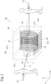
- FIG. 1 is a transparent perspective view showing a cable accommodating body in the first embodiment of the present invention.
- FIG. 1 and FIG. 2(a) to FIG. 2(d) described later a part of the container 20 or the entire container 20 is shown transparently in order to facilitate understanding of the inside of the container 20.
- the cable accommodating body 1A of the present embodiment includes a cable bundle 10 and a container 20 that accommodates the cable bundle 10.
- the cable accommodating body 1A is used, for example, for the transporting work to the installation site and the installing work itself at the time of the installing construction of the cable 11.
- the cable bundle 10 is formed by winding a single continuous cable 11 in an annular shape (coil shape).
- the cable 11 constituting the cable bundle 10 has no connection points between one end (first end) 12 and the other end (second end) 13.
- the single continuous cable 11 may be configured by connecting a plurality of cables, for example, by fusion bonding, connectors, or the like. That is, as long as the cable is continuously connected without being divided between the one end 12 and the other end 13, the "single continuous cable 11" in the present embodiment may have no connection point between the ends 12 and 13 or may have one or more connection points between the ends 12 and 13.
- an optical fiber cable can be exemplified as a specific example of the cable 11, the cable 11 is not particularly limited thereto. For example, a metal cable for power transmission, communication, or a combination of these may be used as the cable 11.
- a traverse winding can be exemplified.
- the method of winding the cable 11 is not particularly limited to the above, and the cable bundle 10 may be configured by winding the cable 11 using other winding methods such as a figure-8 (eight) winding.
- the cable 11 may be wound to form the cable bundle 10 while applying the opposite twist in the direction opposite to the twist at the time of unwinding of the cable 11 every time one winding of the cable 11 by the winding method as described in JP Utility Model Registration No. 3035145 and JP2000-255659A .
- the cable bundle 10 of the present embodiment is formed, for example, by winding the cable 11 using a parasol drum type winding device.
- the completed cable bundle 10 is removed from the winding device by contracting the parasol drum after the winding of the cable 11. Therefore, the cable bundle 10 of the present embodiment has a so-called drumless structure in which the cable bundle 10 has no winding core such as a drum or a reel.
- the cable bundle 10 may be formed using a winding device of a type other than the parasol drum type described above.
- the first end 12 of the cable 11 and the second end 13 of the cable 11 can be simultaneously unwound from the cable bundle 10. That is, it is possible to be simultaneously unwind both ends 12 and 13 of the cable 11 from the cable bundle 10 in the present embodiment.
- the end on the winding end side E end, for example, one end
- the end on the winding start side S end, for example, the other end
- the container 20 is, for example, a box having six planes 21a to 21f and accommodates the cable bundle 10 described above therein.
- the shape of the container 20 is not particularly limited to the above as long as the container 20 has a space that can accommodates the cable bundle 10.
- the container 20 may have cylindrical shape.
- the cable bundle 10 is accommodated in the container 20 in a horizontal posture, and the cable bundle 10 is disposed in the container 20 with a posture (i.e., " horizontal posture") in which the winding axial L 1 of the cable bundle 10 is substantially parallel to the horizontal direction (XY plane direction in the drawing).
- a posture i.e., " horizontal posture”
- the cable bundle 10 may be accommodated in the container in the horizontal posture.
- the container 20 is formed using cardboard made of paper.
- the container 20 may be formed using a plastic cardboard made of a resin material such as polypropylene (PP), or the container 20 may be formed using a metallic box.
- PP polypropylene
- the container 20 of the present embodiment has two outlets 22 and 23.
- the first outlet 22 is formed in a first plane 21a that is the left side plane of the box in FIG. 1 .
- the first outlet 22 penetrates the first plane 21a in the thickness direction of the first plane 21a.
- the second outlet 23 is formed in the second plane 21b that is the right side plane of the box in FIG. 1 .
- the second outlet 23 also penetrates the second plane 21b in the thickness direction of the second plane 21b.
- Both of the first and second planes 21a and 21b are substantially perpendicular to the winding axial direction L 1 of the cable bundle 10, and the first and second outlets 22 and 23 are respectively formed in the first and second planes 21a and 21b that are opposite to each other.
- the cable 11 is pulled out from the container 20 through the first outlet 22, and the first end 12 side of the cable 11 passes through the first outlet 22.
- the cable 11 is also pulled out from the container 20 through the second outlet 23, and the second end 13 side of the cable 11 passes through the second outlet 23.
- FIG. 2(a) to FIG. 2(d) are transparent perspective views showing the first to fourth modifications of the cable accommodating body in the first embodiment of the present invention.
- the cable accommodating body 1A shown in FIG. 1 may be used with being rotated 90 degrees clockwise.
- the first plane 21a is the lid plane of the box in the drawing and the second plane 21b is the bottom plane of the box in the drawing
- the first outlet 22 is located above the cable bundle 10
- the second outlet 23 is located below the cable bundle 10.
- the cable bundle 10 is accommodated in the container 20 in a vertical posture
- the cable bundle 10 is disposed in the container 20 with a posture (i.e., "vertical posture") in which the winding axial direction L 1 of the cable bundle 10 is substantially parallel to the vertical direction (Z direction in the drawing).
- the first and second outlets 22 and 23 may be formed in the third and fourth planes 21c and 21d.
- the first outlet 22 may be formed in the first plane 21a
- the second outlet 23 may be formed in the fourth plane 21d.
- both the first and second outlets 22 and 23 may be formed in the same plane 21a.
- the third and fourth planes 21c and 21d are the side planes of the box in the drawing.
- the third plane 21c and the fourth plane 21d are opposite to each other in FIG. 2(b) , it is not particularly limited thereto.
- the third plane 21c and the fourth plane 21d may be planes adjacent to each other.
- the first and second outlets 22 and 23 may be formed in the planes shown in FIG. 2(a) to FIG. 2(c) .
- the first and second outlets 22 and 23 may be formed in the planes shown in FIG. 2(b) to FIG. 2(d) .
- the container 20 of the present embodiment may have protrusions 24 on the inner wall of the container 20.
- Each of the protrusions 24 has a triangular cross-sectional shape and extends in a direction (Y direction in the drawing) substantially perpendicular to the winding axis L 1 of the cable bundle 10.
- Each of the protrusions 24 is formed of, for example, a cardboard having an L-shaped cross-sectional shape and is formed by being attached to the inner surface of the container 20.
- the cross-sectional shape of the protrusion 24 is not particularly limited to the above as long as it protrudes in a convex shape and may be, for example, a rectangular shape or an arc shape.
- the protrusion 24 may be formed of a plastic cardboard or a metal member instead of a cardboard made of paper.
- the protrusions 24 is disposed on the third and fourth planes 21c and 21d connecting the first plane 21a and the second plane 21b described above.
- the protrusions 24 are disposed on the inner surface of the third plane 21c and are disposed on the inner surface of the fourth plane 21d.
- the third plane 21c is the bottom plane of the box in FIG. 1
- the fourth plane 21d is the lid plane of the box in FIG. 1 .
- the protrusions 24 are arranged in parallel to each other on the upper surface (inner surface) of the third plane 21c to form a wave-shaped structure.
- the protrusions 24 are arranged in parallel to each other on the lower surface (inner surface) of the fourth plane 21d to form a wave-shaped structure.
- the number of protrusions 24 disposed on one plane is not particularly limited and may be arbitrarily set.
- the plane on which the wave-shaped structure consisting of the protrusions 24 is formed is not particularly limited to the above as long as the plane is substantially parallel to the axial L 1 of the cable bundle 10.
- the protrusions 24 may be disposed on the fifth and sixth planes 21e and 21f.
- the fifth plane 21e is the front plane of the box in FIG. 1
- the sixth plane 21f is the back plane of the box in FIG. 1 .
- the protrusions 24 may be disposed on the third to sixth planes 21c to 21f (that is, all the planes of the box substantially parallel to the axial direction L 1 of the cable bundle 10).
- the container may have the convex protrusions 24.
- FIG. 3 is a cross-sectional view showing the fifth modification of the cable accommodating body viewed from the side in the first embodiment of the present invention.
- the inclined surfaces 25a and 25b may be disposed on the planes 21c to 21f substantially parallel to the axial direction L 1 of the cable bundle 10.
- the first inclined surface 25a is inclined with respect to the direction axial L 1 of the cable bundle 10 and has a tapered funnel shape in which the accommodating space narrows as approaching the first outlet 22.
- the second inclined surface 25b is also inclined with respect to the axial direction L 1 of the cable bundle 10 and has a tapered funnel shape in which the accommodating space narrows as approaching the second outlet 23.
- the shape of the cable bundle 10 can be matched to the inclined surfaces 25a and 25b, for example, by varying the number of windings of the cable 11 in the axial direction L 1 of the cable bundle 10.
- the container may have inclined surfaces 25a and 25b.
- the container 20 may not have the protrusions 24 or the inclined surfaces 25a and 25b.
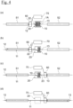
- FIG. 4(a) to FIG. 4(d) are diagrams showing a cable installing method in the first embodiment of the present invention.
- two ducts 51 and 52 are laid.
- the ducts 51 and 52 may be ducts already laid.
- the above-described cable accommodating body 1A is placed between the two ducts 51 and 52, and the jetting machine 60 is set at one end of the first duct 51.
- the operator pulls out the first end 12 of the cable 11 through the first outlet 22 of the container 20 and inserts it into the jetting machine 60.
- the air subjected to the drying process is supplied from the compressor 70 to the jetting machine 60.
- the jetting machine feeds the cable 11 into the first duct 51, for example, by the air and pushing with a caterpillar, and the first end 12 side of the cable 11 is sequentially fed out from the container 20 through the first outlet 22 along with this feeding. Then, when the first end 12 of the cable 11 is exposed from the opposite end of the first duct 51, the jetting machine 60 is stopped. As a result, the installing work of the cable 11 into the first duct 51 is completed.
- the jetting machine 60 is removed from the end of the first duct 51 and is set at one end of the second duct 52. Then, the operator (see FIG. 1 ) pulls out the second end 13 of the cable 11 through the second outlet 23 of the container 20 and inserts the cable 11 into the jetting machine 60.
- the air subjected to the drying process is supplied from the compressor 70 to the jetting machine.
- the cable 11 is fed into the second duct 52 by the air and pushing with the jetting machine 60 to sequentially feed out the second end 13 side of the cable 11 from the container 20 through the second outlet 23.
- the jetting machine 60 is stopped. As a result, the installing work of the cable 11 into the second duct 52 is completed.
- the timing of installation of two ducts 51 and 52 is not particularly limited to this.
- the installing work of the cable 11 into one duct 51 and the installing work of the cable 11 to the other duct 52 may be carried out in parallel.
- it is possible to individually and independently perform the installing work of the cable 11 into the two ducts 51 and 52 without synchronizing by using the cable accommodating body 1A of the present embodiment it is excellent workability.
- the cable bundle 10 since the cable bundle 10 has no winding core and the container 20 accommodating the cable bundle 10 has the first and second outlets 22 and 23 through which the cable 11 is pulled out from the inside of the container 20, it is possible to independently unwind both ends 12 and 13 of the cable 11 from the cable bundle 10.
- FIG. 5(a) is a cross-sectional view showing a cable accommodating body viewed from the side in the second embodiment of the present invention
- FIG. 5(b) is a cross-sectional view taken along VB-VB of FIG. 5(a)
- FIG. 6(a) to FIG. 6(c) are diagrams showing a winding method of a cable bundle in the second embodiment of the present invention.
- the present embodiment is different from the modification shown in FIG. 2(d) of the first embodiment described above mainly in that (a) the cable bundle is divided into a plurality of cable bundles 10A and 10B and (b) the container 20 has a partition plate 26.
- the cable accommodating body 1B in the second embodiment will be described only with respect to differences from the first embodiment, parts having the same configuration as those in the first embodiment are denoted by the same reference numerals, and description thereof will be omitted.
- the cable accommodating body 1B of the present embodiment includes a plurality of (two in the present embodiment) cable bundles 10A and 10B.
- the cable bundles 10A and 10B are continuously connected together by a single cable 11. That is, the cables 11 constituting the cable bundles 10A and 10B has no connection points between the first end 12 and the second end 13.
- the single continuous cable 11 may be configured by connecting a plurality of cables, for example, by fusion bonding, connectors, or the like, and this cable 11 may be used to form a plurality of cable bundles 10A and 10B. In this case, the connection point is preferable located in the cable bundles 10A and 10B.
- the number of the cable bundles included in the cable accommodating body 1B is not particularly limited to the above as long as it is plural.
- the cable bundle 10A and 10B is formed as follows.
- the cable bundle 10B is formed by winding the cable 11 supplied from the supplying drum 80 using the above-described parasol drum type winding device. At this time, the second end 13 of the cable 11 is located below the cable bundle 10B.
- the cable bundle 10B is reversed as shown in FIG. 6(b) .
- the second end 13 of the cable 11 is located above the cable bundle 10B.
- the cable bundle 10A is formed by winding the cable 11 supplied from the supplying drum 80 using the above-described parasol drum type winding device. At this time, the first end 12 of the cable 11 is located above the cable bundle 10B. Since the cable bundle 10A is formed without cutting the cables 11 after forming the cable bundle 10B, the two cable bundles 10A and 10B are continuously connected by the single cable 11.
- the method of forming the cable bundles 10A and 10B is not particularly limited to the above method.
- the cable-bundles 10A and 10B may be formed by the following method. That is, after forming the cable bundle 10B in the manner shown in FIG. 6(a) , the cable bundle 10A is formed without removing the cable bundle 10B from the winding device. Then, after removing the two cable bundles 10A and 10B from the winding device, the cable bundle 10B may be reversed.
- the container 20 of the present embodiment has a partition plate 26, and the partition plate 26 divides the inner space of the container 20 into two accommodating rooms 27a and 27b.
- the two cable bundles 10A and 10B described above are individually accommodated in these two accommodating rooms 27a and 27b.
- the cable bundle 10A is accommodated in the accommodating room 27a
- the cable bundle 10B is accommodated in the accommodating room 27b.
- both cable bundles 10A and 10B are accommodated in the accommodating rooms 27a and 27b in a vertical posture.
- the container 20 may have a plurality of partition plates 26 according to the number of the cable bundles included in the cable accommodating body 1B.
- the container may include a partition plate that partitions the inner space of the container into a plurality of accommodating rooms, and the cable accommodating body may have a plurality of cable bundles individually accommodated in the plurality of accommodating rooms.
- the partition plate 26 has two through holes 28 and 29. Both of the two through holes 28 and 29 penetrate the partition plate 26 in the thickness direction thereof.
- the first end 12 of the cable 11 is pulled out from the inside of the container 20 through the first outlet 22 formed in the first plane 21a of the container 20.
- the part of the cable 11 between the cable bundles 10A and 10B passes through the first through hole 28 of the partition plate 26.
- the second through hole 29 is formed in the partition plate 26 so as to face the second outlet 23 formed in the first plane 21a of the container 20.
- the second end 13 of the cable 11 enters the upper accommodating room 27a from the lower accommodating room 27b through the second through hole 29 and is further pulled out from the inside of the container 20 through the second outlet 23.
- the container 20 accommodating the cable bundles 10A and 10B has the first and second outlets 22 and 23 through which the cable 11 is pulled out from the inside of the container 20, it is possible to independently unwind both ends 12 and 13 of the cable 11 from the cable bundles 10A and 10B.
- the partition plate 26 partitions the inside of the container 20 into a plurality of accommodating rooms 27a and 27b, and the plurality of cable bundles 10A and 10B are individually accommodated in the plurality of accommodating rooms 27a and 27b. Therefore, even when the cable bundles 10A and 10B are disposed in the container 20 in the vertical posture, since the cable 11 can be pulled out upward for both cable bundles 10A and 10B, it is possible to suppress the occurrence of kinking in the cable 11 due to the weight of the cable bundles 10A and 10B or the like. If there is no effect on the cable 11 such as the occurrence of kinking, the outlet 23 may be arranged on the accommodating room 27b side, and the through hole 29 may be omitted.
- FIG. 7(a) is a cross-sectional view showing a cable accommodating body viewed from the side in the third embodiment of the present invention
- FIG. 7(b) is a diagram showing a state in which the inner containers shown in FIG. 7(a) are taken out from the outer container.
- the present embodiment is different from the second embodiment described above mainly in that (a) the plurality of cable bundles 10A and 10B are accommodated in separate containers 20A and 20B and (b) the plurality of containers 20A and 20B are further accommodated in an outer container 30.
- the cable accommodating body 1C in the third embodiment will be described only with respect to differences from the second embodiment, parts having the same configuration as those in the second embodiment are denoted by the same reference numerals, and description thereof will be omitted.
- the cable accommodating body 1C of the present embodiment includes a plurality of (two in the present embodiment) containers 20A and 20B.
- the two containers 20A are stacked in the vertical direction.
- the cable bundles 10A and 10B are individually accommodated in the two containers 20A and 20B. Specifically, one cable bundle 10A is accommodated in the upper container 20A, and the other cable bundle 10B is accommodated in the lower container 20B. At this time, both cable bundles 10A and 10B are accommodated in the containers 20A and 20B in the vertical posture.
- the number of containers included in the cable accommodating body 1C is not particularly limited to the above, and for example, the number of containers can be set according to the number of cable bundles included in the cable accommodating body 1C.
- the first end 12 of the cable 11 is pulled out from the inside of the upper container 20A through the first outlet 22 of the upper container 20A.
- the part of the cable 11 between the cable bundles 10A and 10B passes through the second outlet 23 of the upper container 20A and the first outlet 22 of the lower container 20B. Further, the second end 13 of the cable 11 is pulled out from the inside of the lower container 20B through the second outlet 23 of the lower container 20B.
- the first outlet 22 is formed in the first plane 21a, and the second outlet 23 is formed in the second plane 21b.
- the first outlet 22 is formed in the second plane 21b, and the second outlet 23 is formed in the first plane 21a.
- the second outlet 23 of the upper container 20A may be formed in the side plane of the upper container 20A.
- the first outlet 22 of the lower container 20B may be formed in the side plane of the lower container 20B.
- the cable accommodating body 1C of the present embodiment includes an outer container 30.
- the two containers 20A and 20B are accommodated in the outer container 30 in a state where the containers 20A and 20B are stacked on each other.
- the upper container 20A and the lower container 20B are stacked to be out of alignment, and the second outlet 23 of the lower container 20B is exposed from the upper container 20A.
- the container 20B may be stacked on the container 20A. In this case, the containers 20A and 20B are stacked to be out of alignment so that the first outlet 22 of the container 20A is exposed from the container 20B.
- Third and fourth outlets 32 and 33 are formed in the upper plane 31a of the outer container 30.
- the third outlet 32 faces the first outlet 22 of the upper container 20A.
- the first end 12 of the cable 11 is pulled out from the inside of the upper container 20A to the outside of the outer container 30 through the first outlet 22 of the upper container 20A and the third outlet 32 of the outer container 30.
- the fourth outlet 33 faces the second outlet 23 of the lower container 20B.
- the second end 13 of the cable 11 is pulled out from the inside of the lower container 20B to the outside of the outer container 30 through the second outlet 23 of the lower container 20B and the fourth outlet 33 of the outer container 30.
- the plane of the outer container 30 in which the third and fourth outlets 32 and 33 are formed is not limited to the upper plane 31a, and the third and fourth outlets 32 and 33 may be formed in the side plane or the bottom plane of the outer container 30. The third and fourth outlets 32 and 33 may be formed in different planes of the outer container 30.
- the cable accommodating body may include a plurality of containers.
- a plurality of containers may be stacked on each other such that the winding axial direction of the cable bundle is in the vertical direction.
- the cable accommodating body may include an outer container that accommodates the plurality of containers.
- the first end 12 side of the cable 11 is fed out from the first outlet 22 of the upper container 20A into the first duct 51.
- the second end 13 side of the cable 11 is fed out from the second outlet 23 of the lower container 20B into the second duct 52.
- the cable accommodating body 1C may be placed at the installation site in a state in which the inner containers 20A and 20B are taken out from the outer container 30. Therefore, it is possible to facilitate the short distance transporting of the cable accommodating body 1C at the installation site. Further, even when the space for placing the cable accommodating body at the installation site is small, it is possible to cope with the site by taking out the inner containers 20A and 20B from the outer container 30 and dividing the cable accommodating body 1C into the containers 20A and 20B.
- the containers 20A and 20B accommodating the cable bundles 10A and 10B respectively have the first and second outlets 22 and 23 through which the cable 11 is pulled out from the inside of the containers 20A and 20B, it is possible to independently unwind both ends 12 and 13 of the cable 11 from the cable bundles 10A and 10B.
- the plurality of cable bundles 10A and 10B are individually accommodated in the plurality of containers 20A and 20B. Therefore, even when the cable bundles 10A and 10B are disposed in the containers 20A and 20B in the vertical posture, since the cable 11 can be pulled out upward for both cable bundles 10A and 10B, it is possible to suppress the occurrence of kinking in the cable 11 due to the weight of the cable bundles 10A and 10B or the like.
- the two containers 20A and 20B are accommodated in one outer container 30, it is possible to efficiently transport the cable accommodation body 1C.
- FIG. 8 is a cross-sectional view showing a cable accommodating body viewed from the side in the fourth embodiment of the present invention.
- the present embodiment is different from the third embodiment described above mainly in that the cable accommodating body 1D includes four cable bundles 10A to 10D and four containers 20A to 20D.
- the cable accommodating body 1D in the fourth embodiment will be described only with respect to differences from the third embodiment, parts having the same configuration as those in the third embodiment are denoted by the same reference numerals, and description thereof will be omitted.
- the cable accommodating body 1D of the present embodiment includes two cable bundles 10C and 10D in addition to the two cable bundles 10A and 10B. That is, the cable accommodating body 1D includes four cable bundles 10A to 10D.
- the cable bundles 10A to 10D are continuously connected together by a single cable 11, and the cables 11 constituting the cable bundles 10A to 10D has no connection points between the first end 12 and the second end 13.
- the single continuous cable 11 may be configured by connecting a plurality of cables, for example, by fusion bonding, connectors, or the like, and this cable 11 may be used to form a plurality of cable bundles 10A to 10D.
- the connection point is preferable located in the cable bundles 10A to 10D.
- the cable accommodating body 1D includes two containers 20C and 20D in addition to the two containers 20A and 20B in order to individually accommodate the cable bundles 10A to 10D. That is, the cable accommodating body 1D includes four containers 20A to 20D. Specifically, the cable bundle 10A is accommodated in the container 20A, the cable bundle 10B is accommodated in the container 20B, the cable bundle 10C is accommodated in the container 20C, and the cable bundle 10D is accommodated in the container 20D. At this time, all cable bundles 10A to 10D are accommodated in containers 20A to 20D in the vertical posture.
- the four containers 20A to 20D are stacked in the vertical direction. Specifically, the containers 20C and 20D are stacked between containers 20A and 20B. The four containers 20A to 20D are accommodated in the outer container 30 in a state where the containers 20A to 20D are stacked on each other. At this time, the container 20D and the container 20B are stacked to be out of alignment, and the second outlet 23 of the container 20B is exposed from the container 20D.
- the first end 12 of the cable 11 is pulled out from the inside of the container 20A to the outside of the outer container 30 through the first outlet 22 of the container 20A and the third outlet 32 of the outer container 30.
- the second end 13 of the cable 11 is pulled out from the inside of the container 20B to the outside of the outer container 30 through the second outlet 23 of the container 20B and the fourth outlet 33 of the outer container 30.
- the part of the cable 11 between the cable bundles 10A and 10C passes through the second outlet 23 of the container 20A and the first outlet 22 of the container 20C.
- the part of the cable 11 between the cable bundles 10C and 10D passes through the second outlet 23 of the container 20C and the first outlet 22 of the container 20D.
- the part of the cable 11 between the cable bundles 10D and 10B also passes through the second outlet 23 of the container 20D and the first outlet 22 of the container 20B.
- the first end 12 side of the cable 11 is sequentially fed out from the first outlets 22 of the containers 20A, 20C and 20D into the first duct 51.
- the second end 13 side of the cable 11 is fed out from the second outlet 23 of the container 20B into the second duct 52.
- the cable 11 of the three upper cable bundles 10A, 10C and 10D in the outer container 30 is installed in the first duct 51, and the cable 11 of only the lowest one cable bundle 10B is installed in the second duct 52.
- the cable accommodating body 1D may be placed in a state where the inner containers 20A to 20D are taken out from the outer container 30. Therefore, it is possible to facilitate the short distance transporting of the cable accommodating body 1D at the installation site, and it is also possible to cope with the installation site having a small space.
- the cable bundles 10A to 10D have no winding core and the containers 20A to 20D accommodating the cable bundles 10A to 10D respectively have the first and second outlets 22 and 23 through which the cable 11 is pulled out from the inside of the containers 20A to 20D, it is possible to independently unwind both ends 12 and 13 of the cable 11 from the cable bundles 10A to 10D.
- the plurality of cable bundles 10A to 10D are individually accommodated in the plurality of containers 20A to 20D. Therefore, even when the cable bundles 10A to 10D are disposed in the containers 20A to 20D in the vertical posture, since the cable 11 can be pulled out upward for all the cable bundles 10A to 10D, it is possible to suppress the occurrence of kinking in the cable 11 due to the weight of the cable bundles 10A to 10D or the like.
- FIG. 9 is a transparent perspective view showing a cable accommodating body in the fifth embodiment of the present invention. Similar to FIG. 2(a) to FIG. 2(d) described above, the entire container 20 is shown transparently in FIG. 9 in order to facilitate understanding of the inside of the container 20.
- the present embodiment is different from the second embodiment described above mainly in that (a) the container 20 does not have the partition plate 26 and (b) the other cable bundle 10B is disposed inside one cable bundle 10A.
- the cable accommodating body 1E in the fifth embodiment will be described only with respect to differences from the second embodiment, parts having the same configuration as those in the second embodiment are denoted by the same reference numerals, and description thereof will be omitted.
- the container 20 of the cable accommodating body 1E does not have a partition plate 26
- one cable bundle 10A has the first inner diameter D 1
- the other cable bundle 10B has the first outer diameter D 2 smaller than the first inner diameter D 1 (D 2 ⁇ D 1 ).
- the cable bundle 10B is disposed inside the cable bundle 10A.
- both cable bundles 10A and 10B are accommodated in the container 20 in the vertical posture.
- the cable accommodating body may include first and second cable bundles, and the second cable bundle may be disposed inside the first cable bundle.
- the number of the cable bundles included in the cable accommodating body 1E is not particularly limited to the above as long as it is plural. Also in this case, it is possible to accommodate the plurality of cable bundles in a nested manner by making the diameters of the plurality of cable bundles different from each other.
- the first end 12 of the cable 11 is pulled out from the inside of the container 20 through the first outlet 22 formed in the upper plane 21a of the container 20.
- the second end 13 of the cable 11 is also pulled out from the inside of the container 20 through the second outlet 23 formed in the upper plane 21a of the container 20.
- the container 20 accommodating the cable bundles 10A and 10B has the first and second outlets 22 and 23 through which the cable 11 is pulled out from the inside of the container 20, it is possible to independently unwind both ends 12 and 13 of the cable 11 from the cable bundles 10A and 10B.
- the unwinding work of the first end 12 side of the cable 11 is completed, the unwinding work of the second end 13 side of the cable 11 is started.
Landscapes
- Engineering & Computer Science (AREA)
- Mechanical Engineering (AREA)
- Textile Engineering (AREA)
- Packaging Of Annular Or Rod-Shaped Articles, Wearing Apparel, Cassettes, Or The Like (AREA)
- Storage Of Web-Like Or Filamentary Materials (AREA)
Abstract
Description
- The present invention relates to a cable accommodating body in which a cable bundle is accommodated in a container.
- For designated countries that are permitted to be incorporated by reference in the literature, the contents of Patent Application No.
2022-22471 filed with Japan Patent Office on February 16, 2022 - As an air blown optical cable installing method for increasing a feeding distance of an optical cable unit, for example, a method described in
Patent Document 1 is known. In this method, first, a reel in which both end side parts of the optical fiber unit are simultaneously wound while the intermediate part of the optical fiber unit is fixed to the cylinder is prepared. Next, the reel is disposed between two pipes laid in advance, and the reel is rotated to feed both end side parts of the optical fiber unit into two pipes. - PATENT DOCUMENT 1:
JP H10-45322 A1 - In the above-described method, one of both end side parts of the optical fiber unit is unwound from the upper side of the reel and is fed into one pipe, and the other of both end side parts of the optical fiber unit is unwound from the lower side of the reel and fed into the other pipe. In this way, since both end side parts of the optical fiber unit are simultaneously unwound in the above-described method, it is necessary to prepare two jetting machines, and it is necessary to synchronize the feeding operation into the two pipes.
- The problem to be solved by the present invention is to provide a cable accommodating body capable of independently unwinding both ends of a cable from a cable bundle.
-
- [1] A cable accommodating body according to the present invention is a cable accommodating body comprising: a cable bundle that is formed by winding a cable and has no winding core; and a first container that accommodates the cable bundle, wherein the first container has a first outlet and a second outlet through which the cable is pulled out from an inside of the first container.
- [2] In the above invention, the cable may be a single continuous cable.
- [3] In the above invention, a first end side of the optical fiber cable may pass through the first outlet, and a second end side of the optical fiber cable may pass through the second outlet.
- [4] In the above invention, the first container may comprise a first plane and a second plane that are substantially perpendicular to a winding axial direction of the cable bundle and are opposite to each other, the first outlet may be formed in the first plane, and the second outlet may be formed in the second plane.
- [5] In the above invention, the first container may comprise a convex part or an inclined surface that is disposed on a plane substantially parallel to the winding axial direction of the cable bundle and contacts the cable bundle.
- [6] In the above invention, the cable accommodating body may comprise the cable bundles connected together.
- [7] In the above invention, the cable bundles may be continuously connected together by a single cable.
- [8] In the above invention, the first container may comprise a partition plate that partitions an inner space of the first container into accommodating rooms, and the cable bundles may be individually accommodated in the accommodating rooms.
- [9] In the above invention, the cable accommodating body may comprise the first containers that individually accommodate the cable bundles.
- [10] In the above invention, the first containers may be stacked on each other so that winding axial direction of the cable bundles is in the vertical direction.
- [11] In the above invention, the first containers may include an upper container and a lower container that are stacked on each other, the upper container and the lower container may be stacked to be out of alignment, and the first outlet or the second outlet of the lower container may be exposed from the upper container.
- [12] In the above invention, the cable accommodating body may comprise a second container that accommodates the first containers, and the second container may have a third outlet and a fourth outlet through which the cable is pulled out from an inside of the second container.
- [13] In the above invention, the first end side of the optical fiber cable may pass through the third outlet, and the second end side of the optical fiber cable may pass through the fourth outlet.
- [14] In the above invention, the cable bundles may include: a first cable bundle having a first inner diameter; and a second cable bundle having a first outer diameter smaller than the first inner diameter, and the second cable bundle may be accommodated inside the first cable bundle.
- [15] A method of installing a cable according to the present invention is a method of installing a cable comprising: a first step of preparing a first duct and a second duct; a second step of preparing the cable accommodating body; a third step of pulling out the cable through the first outlet and inserting the cable into the first duct; and a fourth step of pulling out the cable through the second outlet and inserting the cable int the second duct.
- [16] In the above invention, the first step may comprise disposing the first duct and the second duct.
- According to the present invention, since the cable bundle has no winding core and the first container accommodating the cable bundle has the first and second outlets through which the cable is pulled out from the inside of the first container, it is possible to independently unwind both ends of the cable from the cable bundle.
-
-
FIG. 1 is a transparent perspective view showing a cable accommodating body in the first embodiment of the present invention. -
FIG. 2(a) to FIG. 2(d) are transparent perspective views showing the first to fourth modifications of the cable accommodating body in the first embodiment of the present invention. -
FIG. 3 is a cross-sectional view showing the fifth modification of the cable accommodating body viewed from the side in the first embodiment of the present invention. -
FIG. 4(a) to FIG. 4(d) are diagrams showing a cable installing method in the first embodiment of the present invention. -
FIG. 5(a) is a cross-sectional view showing a cable accommodating body viewed from the side in the second embodiment of the present invention, andFIG. 5(b) is a cross-sectional view taken along VB-VB ofFIG. 5(a) . -
FIG. 6(a) to FIG. 6(c) are diagrams showing a winding method of a cable bundle in the second embodiment of the present invention. -
FIG. 7(a) is a cross-sectional view showing a cable accommodating body viewed from the side in the third embodiment of the present invention, andFIG. 7(b) is a diagram showing a state in which the inner containers shown inFIG. 7(a) are taken out from the outer container. -
FIG. 8 is a cross-sectional view showing a cable accommodating body viewed from the side in the fourth embodiment of the present invention. -
FIG. 9 is a transparent perspective view showing a cable accommodating body in the fifth embodiment of the present invention. - Hereinafter, the embodiments of the present invention will be described with reference to the drawings.
-
FIG. 1 is a transparent perspective view showing a cable accommodating body in the first embodiment of the present invention. InFIG. 1 andFIG. 2(a) to FIG. 2(d) described later, a part of thecontainer 20 or theentire container 20 is shown transparently in order to facilitate understanding of the inside of thecontainer 20. - As shown in
FIG. 1 , thecable accommodating body 1A of the present embodiment includes acable bundle 10 and acontainer 20 that accommodates thecable bundle 10. The cable accommodatingbody 1A is used, for example, for the transporting work to the installation site and the installing work itself at the time of the installing construction of thecable 11. - The
cable bundle 10 is formed by winding a singlecontinuous cable 11 in an annular shape (coil shape). In the present embodiment, thecable 11 constituting thecable bundle 10 has no connection points between one end (first end) 12 and the other end (second end) 13. The singlecontinuous cable 11 may be configured by connecting a plurality of cables, for example, by fusion bonding, connectors, or the like. That is, as long as the cable is continuously connected without being divided between the oneend 12 and theother end 13, the "singlecontinuous cable 11" in the present embodiment may have no connection point between theends ends cable 11, thecable 11 is not particularly limited thereto. For example, a metal cable for power transmission, communication, or a combination of these may be used as thecable 11. - As an example of the method of winding the
cable 11 when forming thecable bundle 10, a traverse winding can be exemplified. The method of winding thecable 11 is not particularly limited to the above, and thecable bundle 10 may be configured by winding thecable 11 using other winding methods such as a figure-8 (eight) winding. For example, thecable 11 may be wound to form thecable bundle 10 while applying the opposite twist in the direction opposite to the twist at the time of unwinding of thecable 11 every time one winding of thecable 11 by the winding method as described inJP Utility Model Registration No. 3035145 JP2000-255659A - The
cable bundle 10 of the present embodiment is formed, for example, by winding thecable 11 using a parasol drum type winding device. In the winding device of this type, the completedcable bundle 10 is removed from the winding device by contracting the parasol drum after the winding of thecable 11. Therefore, thecable bundle 10 of the present embodiment has a so-called drumless structure in which thecable bundle 10 has no winding core such as a drum or a reel. As long as thecable bundle 10 does not have a winding core, thecable bundle 10 may be formed using a winding device of a type other than the parasol drum type described above. - In the present embodiment, since the
cable bundle 10 has no winding core, thefirst end 12 of thecable 11 and thesecond end 13 of thecable 11 can be simultaneously unwound from thecable bundle 10. That is, it is possible to be simultaneously unwind bothends cable 11 from thecable bundle 10 in the present embodiment. On the other hand, if the cable bundle is wound around the drum, the end on the winding end side (E end, for example, one end) can be unwound from the cable bundle, but the end on the winding start side (S end, for example, the other end) cannot be unwound from the cable bundle because the end on the winding start side is fixed to the drum. - Further, in the present embodiment, since the
cable bundle 10 has no winding core, it is not necessary to rotate thecable bundle 10 itself when unwinding thecable 11, and it is possible to independently unwind both ends 12 and 13 of thecable 11 from thecable bundle 10. On the other hand, in the method described inPatent Document 1 described above, since it is necessary to simultaneously unwind both ends of the cable with the rotation of the reel, it is impossible to independently unwind both ends of the cable. - The
container 20 is, for example, a box having sixplanes 21a to 21f and accommodates thecable bundle 10 described above therein. The shape of thecontainer 20 is not particularly limited to the above as long as thecontainer 20 has a space that can accommodates thecable bundle 10. For example, thecontainer 20 may have cylindrical shape. By accommodating thecable bundle 10 in such acontainer 20, it is possible to easily transport thecable bundle 10 and to suppress the occurrence of collapse of thecable bundle 10. - In the present embodiment, the
cable bundle 10 is accommodated in thecontainer 20 in a horizontal posture, and thecable bundle 10 is disposed in thecontainer 20 with a posture (i.e., " horizontal posture") in which the winding axial L1 of thecable bundle 10 is substantially parallel to the horizontal direction (XY plane direction in the drawing). In this way, by accommodating thecable bundle 10 in thecontainer 20 in the horizontal posture, it is possible to suppress the occurrence of kinking in thecable 11 due to the weight of thecable bundle 10 or the like. In the second to fifth embodiments described later, thecable bundle 10 may be accommodated in the container in the horizontal posture. - Although not particularly limited, for example, the
container 20 is formed using cardboard made of paper. For example, thecontainer 20 may be formed using a plastic cardboard made of a resin material such as polypropylene (PP), or thecontainer 20 may be formed using a metallic box. - As shown in
FIG. 1 , thecontainer 20 of the present embodiment has twooutlets first outlet 22 is formed in afirst plane 21a that is the left side plane of the box inFIG. 1 . Thefirst outlet 22 penetrates thefirst plane 21a in the thickness direction of thefirst plane 21a. On the other hand, thesecond outlet 23 is formed in thesecond plane 21b that is the right side plane of the box inFIG. 1 . Thesecond outlet 23 also penetrates thesecond plane 21b in the thickness direction of thesecond plane 21b. - Both of the first and
second planes cable bundle 10, and the first andsecond outlets second planes cable 11 is pulled out from thecontainer 20 through thefirst outlet 22, and thefirst end 12 side of thecable 11 passes through thefirst outlet 22. On the other hand, thecable 11 is also pulled out from thecontainer 20 through thesecond outlet 23, and thesecond end 13 side of thecable 11 passes through thesecond outlet 23. - The posture of the
cable bundle 10 in thecontainer 20 and the planes in which the first andsecond outlets FIG. 2(a) to FIG. 2(d) are transparent perspective views showing the first to fourth modifications of the cable accommodating body in the first embodiment of the present invention. - For example, as shown in
FIG. 2(a) , thecable accommodating body 1A shown inFIG. 1 may be used with being rotated 90 degrees clockwise. In this case, since thefirst plane 21a is the lid plane of the box in the drawing and thesecond plane 21b is the bottom plane of the box in the drawing, thefirst outlet 22 is located above thecable bundle 10 and thesecond outlet 23 is located below thecable bundle 10. Further, thecable bundle 10 is accommodated in thecontainer 20 in a vertical posture, thecable bundle 10 is disposed in thecontainer 20 with a posture (i.e., "vertical posture") in which the winding axial direction L1 of thecable bundle 10 is substantially parallel to the vertical direction (Z direction in the drawing). - Alternatively, as shown in
FIG. 2(b) , the first andsecond outlets fourth planes FIG. 2(c) , thefirst outlet 22 may be formed in thefirst plane 21a, and thesecond outlet 23 may be formed in thefourth plane 21d. Alternatively, as shown inFIG. 2(d) , both the first andsecond outlets same plane 21a. InFIG. 2(a) to FIG. 2(d) , the third andfourth planes third plane 21c and thefourth plane 21d are opposite to each other inFIG. 2(b) , it is not particularly limited thereto. For example, thethird plane 21c and thefourth plane 21d may be planes adjacent to each other. - In the second and fifth embodiments, the first and
second outlets FIG. 2(a) to FIG. 2(c) . Alternatively, in the third and fourth embodiments, the first andsecond outlets FIG. 2(b) to FIG. 2(d) . - Returning to
FIG. 1 , thecontainer 20 of the present embodiment may haveprotrusions 24 on the inner wall of thecontainer 20. Each of theprotrusions 24 has a triangular cross-sectional shape and extends in a direction (Y direction in the drawing) substantially perpendicular to the winding axis L1 of thecable bundle 10. Each of theprotrusions 24 is formed of, for example, a cardboard having an L-shaped cross-sectional shape and is formed by being attached to the inner surface of thecontainer 20. The cross-sectional shape of theprotrusion 24 is not particularly limited to the above as long as it protrudes in a convex shape and may be, for example, a rectangular shape or an arc shape. Theprotrusion 24 may be formed of a plastic cardboard or a metal member instead of a cardboard made of paper. - The
protrusions 24 is disposed on the third andfourth planes first plane 21a and thesecond plane 21b described above. Theprotrusions 24 are disposed on the inner surface of thethird plane 21c and are disposed on the inner surface of thefourth plane 21d. Thethird plane 21c is the bottom plane of the box inFIG. 1 , while thefourth plane 21d is the lid plane of the box inFIG. 1 . Theprotrusions 24 are arranged in parallel to each other on the upper surface (inner surface) of thethird plane 21c to form a wave-shaped structure. Similarly, theprotrusions 24 are arranged in parallel to each other on the lower surface (inner surface) of thefourth plane 21d to form a wave-shaped structure. The number ofprotrusions 24 disposed on one plane is not particularly limited and may be arbitrarily set. - By forming such a wave-shaped structure consisting of the
protrusions 24 on theplanes cable bundle 10, it is possible to insert theprotrusions 24 between thecable 11 constituting thecable bundle 10 and to hold thecable 11 by theprotrusions 24. Thus, even when thecable bundle 10 is accommodated in thecontainer 20 in a horizontal posture, it is possible to suppress thecable bundle 10 from falling down or collapsing. - The plane on which the wave-shaped structure consisting of the
protrusions 24 is formed is not particularly limited to the above as long as the plane is substantially parallel to the axial L1 of thecable bundle 10. For example, theprotrusions 24 may be disposed on the fifth andsixth planes fifth plane 21e is the front plane of the box inFIG. 1 , and thesixth plane 21f is the back plane of the box inFIG. 1 . Alternatively, theprotrusions 24 may be disposed on the third tosixth planes 21c to 21f (that is, all the planes of the box substantially parallel to the axial direction L1 of the cable bundle 10). In the second to fifth embodiments, for example, when the cable bundle is accommodated in the container in the horizontal posture, the container may have theconvex protrusions 24. -
FIG. 3 is a cross-sectional view showing the fifth modification of the cable accommodating body viewed from the side in the first embodiment of the present invention. - Instead of the
protrusions 24 described above, as shown inFIG. 3 , theinclined surfaces planes 21c to 21f substantially parallel to the axial direction L1 of thecable bundle 10. The firstinclined surface 25a is inclined with respect to the direction axial L1 of thecable bundle 10 and has a tapered funnel shape in which the accommodating space narrows as approaching thefirst outlet 22. The secondinclined surface 25b is also inclined with respect to the axial direction L1 of thecable bundle 10 and has a tapered funnel shape in which the accommodating space narrows as approaching thesecond outlet 23. - By holding the
entire cable bundle 10 by theinclined surfaces cable bundle 10 is accommodated in thecontainer 20 in a horizontal posture, it is possible to suppress thecable bundle 10 from falling down or collapsing. In the case of the example shown inFIG. 3 , the shape of thecable bundle 10 can be matched to theinclined surfaces cable 11 in the axial direction L1 of thecable bundle 10. In the second to fifth embodiments, for example, when the cable bundle is accommodated in the container in the horizontal position, the container may haveinclined surfaces - For example, when there is no possibility of the
cable bundle 10 falling down or collapsing, or when thecable bundle 10 is disposed in thecontainer 20 in the vertical posture as shown inFIG. 2 (a) to FIG. 2 (d) , thecontainer 20 may not have theprotrusions 24 or theinclined surfaces - Below, the method of installing the
cable 11 by the air blown cable installing method using thecable accommodating body 1A described above will be explained with reference toFIG. 4 (a) to FIG. 4 (d). FIG. 4(a) to FIG. 4(d) are diagrams showing a cable installing method in the first embodiment of the present invention. - First, as shown in
FIG. 4(a) , twoducts ducts accommodating body 1A is placed between the twoducts machine 60 is set at one end of thefirst duct 51. Next, the operator (seeFIG. 1 ) pulls out thefirst end 12 of thecable 11 through thefirst outlet 22 of thecontainer 20 and inserts it into the jettingmachine 60. - Next, as shown in
FIG. 4(b) , the air subjected to the drying process is supplied from thecompressor 70 to the jettingmachine 60. The jetting machine feeds thecable 11 into thefirst duct 51, for example, by the air and pushing with a caterpillar, and thefirst end 12 side of thecable 11 is sequentially fed out from thecontainer 20 through thefirst outlet 22 along with this feeding. Then, when thefirst end 12 of thecable 11 is exposed from the opposite end of thefirst duct 51, the jettingmachine 60 is stopped. As a result, the installing work of thecable 11 into thefirst duct 51 is completed. - Next, as shown in
FIG. 4(c) , the jettingmachine 60 is removed from the end of thefirst duct 51 and is set at one end of thesecond duct 52. Then, the operator (seeFIG. 1 ) pulls out thesecond end 13 of thecable 11 through thesecond outlet 23 of thecontainer 20 and inserts thecable 11 into the jettingmachine 60. - Next, as shown in
FIG. 4(d) , the air subjected to the drying process is supplied from thecompressor 70 to the jetting machine. Thecable 11 is fed into thesecond duct 52 by the air and pushing with the jettingmachine 60 to sequentially feed out thesecond end 13 side of thecable 11 from thecontainer 20 through thesecond outlet 23. Then, when thesecond end 13 of thecable 11 is exposed from the opposite end of thesecond duct 52, the jettingmachine 60 is stopped. As a result, the installing work of thecable 11 into thesecond duct 52 is completed. - Next, after removing the
container 20 of thecable accommodating body 1A from thecable 11, the installing work thecable 11 into theducts ducts - Although the installation of
cable 11 into theother duct 52 is started after the installation ofcable 11 into oneduct 51 is completed in the above-described cable installing method, the timing of installation of twoducts machines 60 can be prepared, the installing work of thecable 11 into oneduct 51 and the installing work of thecable 11 to theother duct 52 may be carried out in parallel. In this case, since it is possible to individually and independently perform the installing work of thecable 11 into the twoducts cable accommodating body 1A of the present embodiment, it is excellent workability. - In the present embodiment, since the
cable bundle 10 has no winding core and thecontainer 20 accommodating thecable bundle 10 has the first andsecond outlets cable 11 is pulled out from the inside of thecontainer 20, it is possible to independently unwind both ends 12 and 13 of thecable 11 from thecable bundle 10. -
FIG. 5(a) is a cross-sectional view showing a cable accommodating body viewed from the side in the second embodiment of the present invention, andFIG. 5(b) is a cross-sectional view taken along VB-VB ofFIG. 5(a) .FIG. 6(a) to FIG. 6(c) are diagrams showing a winding method of a cable bundle in the second embodiment of the present invention. - The present embodiment is different from the modification shown in
FIG. 2(d) of the first embodiment described above mainly in that (a) the cable bundle is divided into a plurality ofcable bundles container 20 has apartition plate 26. Hereinafter, thecable accommodating body 1B in the second embodiment will be described only with respect to differences from the first embodiment, parts having the same configuration as those in the first embodiment are denoted by the same reference numerals, and description thereof will be omitted. - As shown in
FIG. 5(a) , thecable accommodating body 1B of the present embodiment includes a plurality of (two in the present embodiment)cable bundles single cable 11. That is, thecables 11 constituting the cable bundles 10A and 10B has no connection points between thefirst end 12 and thesecond end 13. The singlecontinuous cable 11 may be configured by connecting a plurality of cables, for example, by fusion bonding, connectors, or the like, and thiscable 11 may be used to form a plurality ofcable bundles cable 11 between the cable bundles 10A and 10B (the part of thecable 11 that connects the cable bundles 10A and 10B), it is possible to suppress the occurrence of a defect at the connection point. The number of the cable bundles included in thecable accommodating body 1B is not particularly limited to the above as long as it is plural. - The
cable bundle - That is, first, as shown in
FIG. 6(a) , thecable bundle 10B is formed by winding thecable 11 supplied from the supplyingdrum 80 using the above-described parasol drum type winding device. At this time, thesecond end 13 of thecable 11 is located below thecable bundle 10B. - Next, after removing the
cable bundle 10B from the winding device, thecable bundle 10B is reversed as shown inFIG. 6(b) . As a result, thesecond end 13 of thecable 11 is located above thecable bundle 10B. - Next, as shown in
FIG. 6(c) , thecable bundle 10A is formed by winding thecable 11 supplied from the supplyingdrum 80 using the above-described parasol drum type winding device. At this time, thefirst end 12 of thecable 11 is located above thecable bundle 10B. Since thecable bundle 10A is formed without cutting thecables 11 after forming thecable bundle 10B, the twocable bundles single cable 11. - The method of forming the cable bundles 10A and 10B is not particularly limited to the above method. For example, the cable-
bundles cable bundle 10B in the manner shown inFIG. 6(a) , thecable bundle 10A is formed without removing thecable bundle 10B from the winding device. Then, after removing the twocable bundles cable bundle 10B may be reversed. - Returning to
FIG. 5(a) , thecontainer 20 of the present embodiment has apartition plate 26, and thepartition plate 26 divides the inner space of thecontainer 20 into twoaccommodating rooms cable bundles accommodating rooms cable bundle 10A is accommodated in theaccommodating room 27a, and thecable bundle 10B is accommodated in theaccommodating room 27b. At this time, bothcable bundles accommodating rooms container 20 may have a plurality ofpartition plates 26 according to the number of the cable bundles included in thecable accommodating body 1B. - In the first, third, and fourth embodiments, the container may include a partition plate that partitions the inner space of the container into a plurality of accommodating rooms, and the cable accommodating body may have a plurality of cable bundles individually accommodated in the plurality of accommodating rooms.
- The
partition plate 26 has two throughholes holes partition plate 26 in the thickness direction thereof. Thefirst end 12 of thecable 11 is pulled out from the inside of thecontainer 20 through thefirst outlet 22 formed in thefirst plane 21a of thecontainer 20. The part of thecable 11 between the cable bundles 10A and 10B passes through the first throughhole 28 of thepartition plate 26. The second throughhole 29 is formed in thepartition plate 26 so as to face thesecond outlet 23 formed in thefirst plane 21a of thecontainer 20. Thesecond end 13 of thecable 11 enters the upperaccommodating room 27a from the loweraccommodating room 27b through the second throughhole 29 and is further pulled out from the inside of thecontainer 20 through thesecond outlet 23. - In the present embodiment, since the cable bundles 10A and 10B have no winding core and the
container 20 accommodating the cable bundles 10A and 10B has the first andsecond outlets cable 11 is pulled out from the inside of thecontainer 20, it is possible to independently unwind both ends 12 and 13 of thecable 11 from the cable bundles 10A and 10B. - Further, in the present embodiment, the
partition plate 26 partitions the inside of thecontainer 20 into a plurality ofaccommodating rooms cable bundles accommodating rooms container 20 in the vertical posture, since thecable 11 can be pulled out upward for bothcable bundles cable 11 due to the weight of the cable bundles 10A and 10B or the like. If there is no effect on thecable 11 such as the occurrence of kinking, theoutlet 23 may be arranged on theaccommodating room 27b side, and the throughhole 29 may be omitted. -
FIG. 7(a) is a cross-sectional view showing a cable accommodating body viewed from the side in the third embodiment of the present invention, andFIG. 7(b) is a diagram showing a state in which the inner containers shown inFIG. 7(a) are taken out from the outer container. - The present embodiment is different from the second embodiment described above mainly in that (a) the plurality of
cable bundles separate containers containers outer container 30. Hereinafter, thecable accommodating body 1C in the third embodiment will be described only with respect to differences from the second embodiment, parts having the same configuration as those in the second embodiment are denoted by the same reference numerals, and description thereof will be omitted. - As shown in
FIG. 7(a) , thecable accommodating body 1C of the present embodiment includes a plurality of (two in the present embodiment)containers containers 20A are stacked in the vertical direction. The cable bundles 10A and 10B are individually accommodated in the twocontainers cable bundle 10A is accommodated in theupper container 20A, and theother cable bundle 10B is accommodated in thelower container 20B. At this time, bothcable bundles containers cable accommodating body 1C is not particularly limited to the above, and for example, the number of containers can be set according to the number of cable bundles included in thecable accommodating body 1C. - The
first end 12 of thecable 11 is pulled out from the inside of theupper container 20A through thefirst outlet 22 of theupper container 20A. The part of thecable 11 between the cable bundles 10A and 10B passes through thesecond outlet 23 of theupper container 20A and thefirst outlet 22 of thelower container 20B. Further, thesecond end 13 of thecable 11 is pulled out from the inside of thelower container 20B through thesecond outlet 23 of thelower container 20B. - In the present embodiment, in the
upper container 20A, thefirst outlet 22 is formed in thefirst plane 21a, and thesecond outlet 23 is formed in thesecond plane 21b. On the other hand, in thelower container 20B, thefirst outlet 22 is formed in thesecond plane 21b, and thesecond outlet 23 is formed in thefirst plane 21a. Thesecond outlet 23 of theupper container 20A may be formed in the side plane of theupper container 20A. Thefirst outlet 22 of thelower container 20B may be formed in the side plane of thelower container 20B. - Further, the
cable accommodating body 1C of the present embodiment includes anouter container 30. The twocontainers outer container 30 in a state where thecontainers upper container 20A and thelower container 20B are stacked to be out of alignment, and thesecond outlet 23 of thelower container 20B is exposed from theupper container 20A. Thecontainer 20B may be stacked on thecontainer 20A. In this case, thecontainers first outlet 22 of thecontainer 20A is exposed from thecontainer 20B. - Third and
fourth outlets upper plane 31a of theouter container 30. Thethird outlet 32 faces thefirst outlet 22 of theupper container 20A. Thefirst end 12 of thecable 11 is pulled out from the inside of theupper container 20A to the outside of theouter container 30 through thefirst outlet 22 of theupper container 20A and thethird outlet 32 of theouter container 30. Similarly, thefourth outlet 33 faces thesecond outlet 23 of thelower container 20B. Thesecond end 13 of thecable 11 is pulled out from the inside of thelower container 20B to the outside of theouter container 30 through thesecond outlet 23 of thelower container 20B and thefourth outlet 33 of theouter container 30. The plane of theouter container 30 in which the third andfourth outlets upper plane 31a, and the third andfourth outlets outer container 30. The third andfourth outlets outer container 30. - In the first, second, and fifth embodiments, the cable accommodating body may include a plurality of containers. In this case, a plurality of containers may be stacked on each other such that the winding axial direction of the cable bundle is in the vertical direction. In the first, second, and fifth embodiments, the cable accommodating body may include an outer container that accommodates the plurality of containers.
- When the
cable 11 is installed using thecable accommodating body 1C of the present embodiment, thefirst end 12 side of thecable 11 is fed out from thefirst outlet 22 of theupper container 20A into thefirst duct 51. On the other hand, thesecond end 13 side of thecable 11 is fed out from thesecond outlet 23 of thelower container 20B into thesecond duct 52. - As shown in
FIG. 7(b) , thecable accommodating body 1C may be placed at the installation site in a state in which theinner containers outer container 30. Therefore, it is possible to facilitate the short distance transporting of thecable accommodating body 1C at the installation site. Further, even when the space for placing the cable accommodating body at the installation site is small, it is possible to cope with the site by taking out theinner containers outer container 30 and dividing thecable accommodating body 1C into thecontainers - In the present embodiment, since the cable bundles 10A and 10B have no winding core and the
containers second outlets cable 11 is pulled out from the inside of thecontainers cable 11 from the cable bundles 10A and 10B. - Further, in the present embodiment, the plurality of
cable bundles containers containers cable 11 can be pulled out upward for bothcable bundles cable 11 due to the weight of the cable bundles 10A and 10B or the like. - Further, in the present embodiment, since the two
containers outer container 30, it is possible to efficiently transport thecable accommodation body 1C. -
FIG. 8 is a cross-sectional view showing a cable accommodating body viewed from the side in the fourth embodiment of the present invention. - The present embodiment is different from the third embodiment described above mainly in that the
cable accommodating body 1D includes fourcable bundles 10A to 10D and fourcontainers 20A to 20D. Hereinafter, thecable accommodating body 1D in the fourth embodiment will be described only with respect to differences from the third embodiment, parts having the same configuration as those in the third embodiment are denoted by the same reference numerals, and description thereof will be omitted. - As shown in
FIG. 8 , thecable accommodating body 1D of the present embodiment includes twocable bundles cable bundles cable accommodating body 1D includes fourcable bundles 10A to 10D. The cable bundles 10A to 10D are continuously connected together by asingle cable 11, and thecables 11 constituting the cable bundles 10A to 10D has no connection points between thefirst end 12 and thesecond end 13. The singlecontinuous cable 11 may be configured by connecting a plurality of cables, for example, by fusion bonding, connectors, or the like, and thiscable 11 may be used to form a plurality ofcable bundles 10A to 10D. In this case, the connection point is preferable located in the cable bundles 10A to 10D. - Further, the
cable accommodating body 1D includes twocontainers containers cable accommodating body 1D includes fourcontainers 20A to 20D. Specifically, thecable bundle 10A is accommodated in thecontainer 20A, thecable bundle 10B is accommodated in thecontainer 20B, thecable bundle 10C is accommodated in thecontainer 20C, and thecable bundle 10D is accommodated in thecontainer 20D. At this time, allcable bundles 10A to 10D are accommodated incontainers 20A to 20D in the vertical posture. - In the present embodiment, the four
containers 20A to 20D are stacked in the vertical direction. Specifically, thecontainers containers containers 20A to 20D are accommodated in theouter container 30 in a state where thecontainers 20A to 20D are stacked on each other. At this time, thecontainer 20D and thecontainer 20B are stacked to be out of alignment, and thesecond outlet 23 of thecontainer 20B is exposed from thecontainer 20D. - The
first end 12 of thecable 11 is pulled out from the inside of thecontainer 20A to the outside of theouter container 30 through thefirst outlet 22 of thecontainer 20A and thethird outlet 32 of theouter container 30. On the other hand, thesecond end 13 of thecable 11 is pulled out from the inside of thecontainer 20B to the outside of theouter container 30 through thesecond outlet 23 of thecontainer 20B and thefourth outlet 33 of theouter container 30. - The part of the
cable 11 between thecable bundles second outlet 23 of thecontainer 20A and thefirst outlet 22 of thecontainer 20C. Similarly, the part of thecable 11 between the cable bundles 10C and 10D passes through thesecond outlet 23 of thecontainer 20C and thefirst outlet 22 of thecontainer 20D. Further, the part of thecable 11 between the cable bundles 10D and 10B also passes through thesecond outlet 23 of thecontainer 20D and thefirst outlet 22 of thecontainer 20B. - When the
cable 11 is installed using thecable accommodating body 1D of the present embodiment, thefirst end 12 side of thecable 11 is sequentially fed out from thefirst outlets 22 of thecontainers first duct 51. On the other hand, thesecond end 13 side of thecable 11 is fed out from thesecond outlet 23 of thecontainer 20B into thesecond duct 52. - That is, in the present embodiment, since the
first duct 51 is longer than thesecond duct 52, thecable 11 of the three upper cable bundles 10A, 10C and 10D in theouter container 30 is installed in thefirst duct 51, and thecable 11 of only the lowest onecable bundle 10B is installed in thesecond duct 52. In this way, in the present embodiment, it is possible to set the number of the cable bundles in which thecable 11 installed in thefirst duct 51 is wound and the number of the cable bundles in which thecable 11 installed in thesecond duct 52 is wound according to the length of each of theducts - Although not particularly shown, at the installation site, the
cable accommodating body 1D may be placed in a state where theinner containers 20A to 20D are taken out from theouter container 30. Therefore, it is possible to facilitate the short distance transporting of thecable accommodating body 1D at the installation site, and it is also possible to cope with the installation site having a small space. - In the present embodiment, since the cable bundles 10A to 10D have no winding core and the
containers 20A to 20D accommodating the cable bundles 10A to 10D respectively have the first andsecond outlets cable 11 is pulled out from the inside of thecontainers 20A to 20D, it is possible to independently unwind both ends 12 and 13 of thecable 11 from the cable bundles 10A to 10D. - Further, in the present embodiment, the plurality of
cable bundles 10A to 10D are individually accommodated in the plurality ofcontainers 20A to 20D. Therefore, even when the cable bundles 10A to 10D are disposed in thecontainers 20A to 20D in the vertical posture, since thecable 11 can be pulled out upward for all the cable bundles 10A to 10D, it is possible to suppress the occurrence of kinking in thecable 11 due to the weight of the cable bundles 10A to 10D or the like. - Further, in the present embodiment, since the four
containers 20A to 20D are accommodated in oneouter container 30, it is possible to efficiently transport thecable accommodation body 1D. -
FIG. 9 is a transparent perspective view showing a cable accommodating body in the fifth embodiment of the present invention. Similar toFIG. 2(a) to FIG. 2(d) described above, theentire container 20 is shown transparently inFIG. 9 in order to facilitate understanding of the inside of thecontainer 20. - The present embodiment is different from the second embodiment described above mainly in that (a) the
container 20 does not have thepartition plate 26 and (b) theother cable bundle 10B is disposed inside onecable bundle 10A. Hereinafter, thecable accommodating body 1E in the fifth embodiment will be described only with respect to differences from the second embodiment, parts having the same configuration as those in the second embodiment are denoted by the same reference numerals, and description thereof will be omitted. - In the present embodiment, since the
container 20 of thecable accommodating body 1E does not have apartition plate 26, onecable bundle 10A has the first inner diameter D1, whereas theother cable bundle 10B has the first outer diameter D2 smaller than the first inner diameter D1 (D2<D1). Thecable bundle 10B is disposed inside thecable bundle 10A. At this time, bothcable bundles container 20 in the vertical posture. In the first to fourth embodiments, the cable accommodating body may include first and second cable bundles, and the second cable bundle may be disposed inside the first cable bundle. - The number of the cable bundles included in the
cable accommodating body 1E is not particularly limited to the above as long as it is plural. Also in this case, it is possible to accommodate the plurality of cable bundles in a nested manner by making the diameters of the plurality of cable bundles different from each other. - The
first end 12 of thecable 11 is pulled out from the inside of thecontainer 20 through thefirst outlet 22 formed in theupper plane 21a of thecontainer 20. Thesecond end 13 of thecable 11 is also pulled out from the inside of thecontainer 20 through thesecond outlet 23 formed in theupper plane 21a of thecontainer 20. - In the present embodiment, since the cable bundles 10A and 10B have no winding core and the
container 20 accommodating the cable bundles 10A and 10B has the first andsecond outlets cable 11 is pulled out from the inside of thecontainer 20, it is possible to independently unwind both ends 12 and 13 of thecable 11 from the cable bundles 10A and 10B. In the present embodiment, after the unwinding work of thefirst end 12 side of thecable 11 is completed, the unwinding work of thesecond end 13 side of thecable 11 is started. - It should be noted that the embodiment described above are described to facilitate understanding of the present disclosure and are not described to limit the present disclosure. It is therefore intended that the elements disclosed in the above embodiment include all design modifications and equivalents to fall within the technical scope of the present disclosure.
-
- 1A to 1E ... Cable accommodating body
- 10 ... Cable bundle
- 11 ... Cable
- 12 ... First end
- 13 ... Second end
- 20, 20A to 20D ... Container
- 21a to 21f ... First to sixth plane
- 22 ... First outlet
- 23 ... Second outlet
- 24 ... Protrusion
- 25a, 25b ... Inclined surface
- 26 ... Partition plate
- 27a, 27b ... Accommodating room
- 28, 29 ... Through hall
- 30 ... Outer container
- 31a ... Upper surface
- 32 ... Third outlet
- 33 ... Fourth outlet
- 51, 52 ... Duct
- 60 ... Jetting machine
- 70 ... Compressor
- 80 ... Supplying drum
Claims (10)
- A cable accommodating body comprising:a cable bundle that is formed by winding a cable and has no winding core; anda first container that accommodates the cable bundle, whereinthe first container has a first outlet and a second outlet through which the cable is pulled out from an inside of the first container.
- The cable accommodating body according to claim 1, wherein,the first container comprises a first plane and a second plane that are substantially perpendicular to a winding axial direction of the cable bundle and are opposite to each other,the first outlet is formed in the first plane, andthe second outlet is formed in the second plane.
- The cable accommodating body according to claim 2, wherein,
the first container comprises a convex part or an inclined surface that is disposed on a plane substantially parallel to the winding axial direction of the cable bundle and contacts the cable bundle. - The cable accommodating body according to any one of claims 1 to 3, comprising the cable bundles connected together.
- The cable accommodating body according to claim 4, whereinthe first container comprises a partition plate that partitions an inner space of the first container into accommodating rooms, andthe cable bundles are individually accommodated in the accommodating rooms.
- The cable accommodating body according to claim 4, comprising the first containers that individually accommodate the cable bundles.
- The cable accommodating body according to claim 6, wherein
the first containers are stacked on each other so that winding axial directions of the cable bundles is in the vertical direction. - The cable accommodating body according to claim 7, whereinthe first containers include an upper container and a lower container that are stacked on each other,the upper container and the lower container are stacked to be out of alignment, andthe first outlet or the second outlet of the lower container is exposed from the upper container.
- The cable accommodating body according to any one of claims 6 to 8, comprising a second container that accommodates the first containers, wherein
the second container has a third outlet and a fourth outlet through which the cable is pulled out from an inside of the second container. - The cable accommodating body according to claim 4, wherein
the cable bundles include:a first cable bundle having a first inner diameter; anda second cable bundle having a first outer diameter smaller than the first inner diameter, andthe second cable bundle is accommodated inside the first cable bundle.
Applications Claiming Priority (2)
| Application Number | Priority Date | Filing Date | Title |
|---|---|---|---|
| JP2022022471 | 2022-02-16 | ||
| PCT/JP2023/003582 WO2023157674A1 (en) | 2022-02-16 | 2023-02-03 | Cable accommodating body |
Publications (2)
| Publication Number | Publication Date |
|---|---|
| EP4480877A1 true EP4480877A1 (en) | 2024-12-25 |
| EP4480877A4 EP4480877A4 (en) | 2026-03-04 |
Family
ID=87578549
Family Applications (1)
| Application Number | Title | Priority Date | Filing Date |
|---|---|---|---|
| EP23756201.2A Pending EP4480877A4 (en) | 2022-02-16 | 2023-02-03 | CABLE RECEIVING BODY |
Country Status (5)
| Country | Link |
|---|---|
| US (1) | US20250026607A1 (en) |
| EP (1) | EP4480877A4 (en) |
| JP (1) | JP7633467B2 (en) |
| TW (1) | TWI846313B (en) |
| WO (1) | WO2023157674A1 (en) |
Families Citing this family (1)
| Publication number | Priority date | Publication date | Assignee | Title |
|---|---|---|---|---|
| US20250136405A1 (en) * | 2023-11-01 | 2025-05-01 | Lockheed Martin Corporation | Cable management drive system for industrial robots |
Family Cites Families (28)
| Publication number | Priority date | Publication date | Assignee | Title |
|---|---|---|---|---|
| JPS4317910Y1 (en) * | 1965-10-27 | 1968-07-24 | ||
| JPS526060Y2 (en) * | 1971-03-06 | 1977-02-08 | ||
| US3984064A (en) * | 1975-06-30 | 1976-10-05 | Aluminum Company Of America | Non-rotating payoff structure |
| US4451014A (en) * | 1982-08-11 | 1984-05-29 | Mossberg Industries, Inc. | Wire storing and dereeling apparatus |
| JPS63252883A (en) * | 1987-04-10 | 1988-10-19 | Eishin Giken:Kk | Wire accommodation case |
| JPH01209284A (en) * | 1988-02-17 | 1989-08-23 | Nippon Kosoku Tsushin Kk | Cable handling device |
| JP3346872B2 (en) * | 1994-01-26 | 2002-11-18 | 住友化学工業株式会社 | Method of removing fiber bundle and method of manufacturing long fiber reinforced resin structure |
| JP3035145B2 (en) | 1994-02-21 | 2000-04-17 | 株式会社タハラ | Method for controlling wall thickness of parison in blow molding machine |
| US5421457A (en) * | 1994-06-14 | 1995-06-06 | Listenberger; Paul A. | Cord bucket |
| SE507675C2 (en) * | 1996-01-03 | 1998-07-06 | Sahlins Maskin Ab | Method of manufacturing a package for an elongated flexible member wound into a roll form |
| JPH1149435A (en) * | 1997-07-31 | 1999-02-23 | Furukawa Electric Co Ltd:The | Linear box |
| JP2000255659A (en) | 1999-03-12 | 2000-09-19 | Daiden Co Ltd | Wound bobbin of electrical wire and cable |
| US6648141B2 (en) * | 2001-09-04 | 2003-11-18 | Lincoln Global, Inc. | Packaging for containing and dispensing large quantities of wire |
| ITTO20010894A1 (en) * | 2001-09-19 | 2003-03-19 | Sidergas Srl | CONTAINER OF A WELDING WIRE. |
| US20060196989A1 (en) * | 2005-03-04 | 2006-09-07 | Harold Bartley | Stackable dispenser for coiled materials |
| DE102007043719B3 (en) * | 2007-09-13 | 2009-07-30 | Atlas Elektronik Gmbh | Process for producing a glass fiber spool |
| US7975951B2 (en) * | 2008-02-22 | 2011-07-12 | Mary Sara Arnoff | Systems and methods for managing yarn |
| US8313054B2 (en) * | 2010-01-29 | 2012-11-20 | Lincoln Global, Inc. | Wire dispensing system including wire payoff structure |
| US20110248112A1 (en) * | 2010-03-23 | 2011-10-13 | James Corbett | Non-Twist Tape Package and Method of Non-Twist Unwinding of Tape |
| US20140183294A1 (en) * | 2012-12-28 | 2014-07-03 | Lincoln Global, Inc. | Wire control strip for a welding system |
| US9446928B2 (en) * | 2014-01-17 | 2016-09-20 | Honeywell International Inc. | Inertia braking payout device and package system |
| CN106536392A (en) * | 2014-07-23 | 2017-03-22 | 博世株式会社 | Roll and roll manufacturing method |
| US10703557B2 (en) * | 2017-06-07 | 2020-07-07 | Illinois Tool Works Inc. | Drums for transporting and feeding wire |
| US10435267B2 (en) * | 2017-09-01 | 2019-10-08 | Quawana Renia Ashton | Container for thread distribution and needle storage |
| US11059691B2 (en) * | 2019-06-07 | 2021-07-13 | Plasticos y Alambres, S.A. DE C.V. | Container with anti-wire-entangling device for packaging and paying out coiled welding wire |
| US11491723B2 (en) * | 2019-08-09 | 2022-11-08 | Stratasys, Inc. | Consumable assembly |
| CN210558512U (en) * | 2019-08-13 | 2020-05-19 | 浙江一舟电子科技股份有限公司 | Packaging structure for fast outgoing line of network line |
| JP2022022471A (en) | 2020-07-25 | 2022-02-04 | 昌永 戸塚 | Four-dimensional coil |
-
2023
- 2023-02-03 WO PCT/JP2023/003582 patent/WO2023157674A1/en not_active Ceased
- 2023-02-03 US US18/715,511 patent/US20250026607A1/en active Pending
- 2023-02-03 JP JP2024501288A patent/JP7633467B2/en active Active
- 2023-02-03 EP EP23756201.2A patent/EP4480877A4/en active Pending
- 2023-02-09 TW TW112104525A patent/TWI846313B/en active
Also Published As
| Publication number | Publication date |
|---|---|
| TW202346189A (en) | 2023-12-01 |
| JP7633467B2 (en) | 2025-02-19 |
| JPWO2023157674A1 (en) | 2023-08-24 |
| WO2023157674A1 (en) | 2023-08-24 |
| EP4480877A4 (en) | 2026-03-04 |
| US20250026607A1 (en) | 2025-01-23 |
| TWI846313B (en) | 2024-06-21 |
Similar Documents
| Publication | Publication Date | Title |
|---|---|---|
| EP2811596B1 (en) | Fiber optic outlet box assembly and method of installing a fiber optic cable | |
| US10183833B2 (en) | Cable spool assembly | |
| EP4480877A1 (en) | Cable accommodating body | |
| JP4609864B2 (en) | Cable packaging | |
| TWI781423B (en) | Optical cable wiring method | |
| US12105339B2 (en) | Wiring module, frame body for wiring module, and forming method for forming wiring module | |
| KR20230139013A (en) | Corrugated box-type electric wire pulling box | |
| JP6603292B2 (en) | Optical cable branch and method for manufacturing optical cable branch | |
| US12255447B2 (en) | Conduit guide and spacer system | |
| ITMI971975A1 (en) | FIBER OPTIC ORGANIZER-SEPARATOR DEVICE | |
| CN223065567U (en) | An optical cable reel system with multiple slots on both sides | |
| KR101051080B1 (en) | Optical cable installation method and wiring installation structure of communication device box | |
| WO2022224590A1 (en) | Pipeline and method for laying cable | |
| JPH08240723A (en) | Connection terminal box for optical fiber cable | |
| JPH0641350B2 (en) | Cable laying / erection method | |
| JPH08227018A (en) | Optical cable closure | |
| JP2005122036A (en) | Holding and pulling out work method of optical drop cable and, winding tool | |
| JPH0420463A (en) | Electric wire supply | |
| JPH09159892A (en) | Air flow wiring method for optical fiber and air flow wiring system | |
| JPH08292330A (en) | Branch optical fiber storage tray | |
| JPS61221710A (en) | Optical distribution rack | |
| JPH1141737A (en) | Installation method of conduit |
Legal Events
| Date | Code | Title | Description |
|---|---|---|---|
| STAA | Information on the status of an ep patent application or granted ep patent |
Free format text: STATUS: THE INTERNATIONAL PUBLICATION HAS BEEN MADE |
|
| PUAI | Public reference made under article 153(3) epc to a published international application that has entered the european phase |
Free format text: ORIGINAL CODE: 0009012 |
|
| STAA | Information on the status of an ep patent application or granted ep patent |
Free format text: STATUS: REQUEST FOR EXAMINATION WAS MADE |
|
| 17P | Request for examination filed |
Effective date: 20240522 |
|
| AK | Designated contracting states |
Kind code of ref document: A1 Designated state(s): AL AT BE BG CH CY CZ DE DK EE ES FI FR GB GR HR HU IE IS IT LI LT LU LV MC ME MK MT NL NO PL PT RO RS SE SI SK SM TR |
|
| DAV | Request for validation of the european patent (deleted) | ||
| DAX | Request for extension of the european patent (deleted) | ||
| A4 | Supplementary search report drawn up and despatched |
Effective date: 20260129 |
|
| RIC1 | Information provided on ipc code assigned before grant |
Ipc: B65H 49/02 20060101AFI20260123BHEP Ipc: B65H 75/36 20060101ALI20260123BHEP Ipc: B65D 25/10 20060101ALI20260123BHEP Ipc: B65D 85/04 20060101ALI20260123BHEP Ipc: B65H 49/08 20060101ALI20260123BHEP Ipc: B65H 55/04 20060101ALI20260123BHEP |