EP4480869A1 - Rail connection structure - Google Patents
Rail connection structure Download PDFInfo
- Publication number
- EP4480869A1 EP4480869A1 EP23756074.3A EP23756074A EP4480869A1 EP 4480869 A1 EP4480869 A1 EP 4480869A1 EP 23756074 A EP23756074 A EP 23756074A EP 4480869 A1 EP4480869 A1 EP 4480869A1
- Authority
- EP
- European Patent Office
- Prior art keywords
- rail
- base block
- rails
- mounting members
- connecting structure
- Prior art date
- Legal status (The legal status is an assumption and is not a legal conclusion. Google has not performed a legal analysis and makes no representation as to the accuracy of the status listed.)
- Pending
Links
Images





Classifications
-
- F—MECHANICAL ENGINEERING; LIGHTING; HEATING; WEAPONS; BLASTING
- F16—ENGINEERING ELEMENTS AND UNITS; GENERAL MEASURES FOR PRODUCING AND MAINTAINING EFFECTIVE FUNCTIONING OF MACHINES OR INSTALLATIONS; THERMAL INSULATION IN GENERAL
- F16C—SHAFTS; FLEXIBLE SHAFTS; ELEMENTS OR CRANKSHAFT MECHANISMS; ROTARY BODIES OTHER THAN GEARING ELEMENTS; BEARINGS
- F16C29/00—Bearings for parts moving only linearly
- F16C29/005—Guide rails or tracks for a linear bearing, i.e. adapted for movement of a carriage or bearing body there along
-
- E—FIXED CONSTRUCTIONS
- E01—CONSTRUCTION OF ROADS, RAILWAYS, OR BRIDGES
- E01B—PERMANENT WAY; PERMANENT-WAY TOOLS; MACHINES FOR MAKING RAILWAYS OF ALL KINDS
- E01B5/00—Rails; Guard rails; Distance-keeping means for them
- E01B5/02—Rails
-
- E—FIXED CONSTRUCTIONS
- E01—CONSTRUCTION OF ROADS, RAILWAYS, OR BRIDGES
- E01B—PERMANENT WAY; PERMANENT-WAY TOOLS; MACHINES FOR MAKING RAILWAYS OF ALL KINDS
- E01B25/00—Tracks for special kinds of railways
- E01B25/30—Tracks for magnetic suspension or levitation vehicles
-
- E—FIXED CONSTRUCTIONS
- E01—CONSTRUCTION OF ROADS, RAILWAYS, OR BRIDGES
- E01B—PERMANENT WAY; PERMANENT-WAY TOOLS; MACHINES FOR MAKING RAILWAYS OF ALL KINDS
- E01B25/00—Tracks for special kinds of railways
- E01B25/30—Tracks for magnetic suspension or levitation vehicles
- E01B25/305—Rails or supporting constructions
-
- F—MECHANICAL ENGINEERING; LIGHTING; HEATING; WEAPONS; BLASTING
- F16—ENGINEERING ELEMENTS AND UNITS; GENERAL MEASURES FOR PRODUCING AND MAINTAINING EFFECTIVE FUNCTIONING OF MACHINES OR INSTALLATIONS; THERMAL INSULATION IN GENERAL
- F16C—SHAFTS; FLEXIBLE SHAFTS; ELEMENTS OR CRANKSHAFT MECHANISMS; ROTARY BODIES OTHER THAN GEARING ELEMENTS; BEARINGS
- F16C29/00—Bearings for parts moving only linearly
- F16C29/04—Ball or roller bearings
-
- B—PERFORMING OPERATIONS; TRANSPORTING
- B65—CONVEYING; PACKING; STORING; HANDLING THIN OR FILAMENTARY MATERIAL
- B65G—TRANSPORT OR STORAGE DEVICES, e.g. CONVEYORS FOR LOADING OR TIPPING, SHOP CONVEYOR SYSTEMS OR PNEUMATIC TUBE CONVEYORS
- B65G2812/00—Indexing codes relating to the kind or type of conveyors
- B65G2812/99—Conveyor systems not otherwise provided for
-
- B—PERFORMING OPERATIONS; TRANSPORTING
- B65—CONVEYING; PACKING; STORING; HANDLING THIN OR FILAMENTARY MATERIAL
- B65G—TRANSPORT OR STORAGE DEVICES, e.g. CONVEYORS FOR LOADING OR TIPPING, SHOP CONVEYOR SYSTEMS OR PNEUMATIC TUBE CONVEYORS
- B65G54/00—Non-mechanical conveyors not otherwise provided for
- B65G54/02—Non-mechanical conveyors not otherwise provided for electrostatic, electric, or magnetic
Definitions
- the present invention relates to a rail connecting structure that connects rails to be mounted on rail mounting members.
- a common method is to provide two reference surfaces (surfaces against which bottom surfaces and side surfaces of the rails abut) on a rail mounting member side, press the two rails against the reference surfaces with a strong force by use of a vise and bolts, and fix the rails without misalignment therebetween.
- This is because the generation of a level difference at a connecting portion of the rails causes adverse effects on the movement and life of a carriage that moves along the rails.
- this method is based on the premise that the two reference surfaces are formed on one integrated component and there is no mutual error between the reference surfaces against which one rail and the other rail abut.
- the rail mounting members 4 and 5 are frames.
- the rail mounting members 4 and 5 are fastened to a base such as a floor, a surface plate, or a trestle with fastening members such as bolts.
- a reference surface against which the rail mounting members 4 and 5 abut is formed on the base to which the rail mounting members 4 and 5 are fastened.
- the rail mounting members 4 and 5 are formed with mounting holes 4a through which the fastening members pass.
- the rail mounting member 4 and the rail mounting member 5 are connected together by use of, for example, a positioning pin and a connecting plate. Note that the positioning pin and the connecting plate may be omitted.
- the rails 6 and 7 are mounted on the rail mounting members 4 and 5.
- a connecting portion 15 of the rail mounting members 4 and 5 and the connecting portion 14 of the rails 6 and 7 are at substantially the same position, but may be misaligned.
- Mounting holes 6a and 7a such as counterbores through which fastening members are passed are formed in top surfaces of the rails 6 and 7.
- Rolling surfaces 6b and 7b on which the rollers of the traveling bodies 11 and 12 roll are formed on side surfaces of the rails 6 and 7.
- the rails 6 and 7 are fastened to the rail mounting members 4 and 5 with fastening members such as bolts.
- Two reference surfaces 4b and 4c against which the rails 6 and 7 abut are formed on the rail mounting members 4 and 5 (refer to Fig. 3 ).
- the rails 6 and 7 are fastened to the rail mounting members 4 and 5 with the rails 6 and 7 abutting against the reference surfaces 4b and 4c of the rail mounting members 4 and 5.
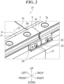
- Figs. 2 and 3 illustrate enlarged views of the rail connecting structure 21 of the present embodiment.
- Fig. 3 illustrates a state in which one rail 6 has been removed.
- the reference signs 4 and 5 denote the rail mounting members, the reference signs 6 and 7 denote the rails, and a reference sign 22 denotes a base block.
- the base block 22 is placed at the connecting portion 14 of the rail 6 and the rail 7.
- the rail mounting members 4 and 5 are formed with notches 4d and 5d for placing the base block 22 therein.
- the rails 6 and 7 are fastened to the base block 22 with fastening members such as bolts.
- a top surface 22a of the base block 22 is formed with female threads 27 that are threadedly engaged with the fastening members, at positions corresponding to the mounting holes 6a and 7a at ends of the rails 6 and 7.
- the base block 22 is formed with a reference surface 22b against which side surfaces of the rails 6 and 7 abut.
- the rails 6 and 7 are fastened to the base block 22 with the side surfaces of the rails 6 and 7 abutting against the reference surface 22b. Note that although the fastening members are omitted in Figs. 2 and 3 , there actually are the fastening members.
- the base block 22 is separate from the rail mounting members 4 and 5. There are gaps g1 to g3 (the gap g1 in a front-and-back direction, the gap g2 in a left-and-right direction, and the gap g3 in an up-and-down direction (refer to Fig. 4 )) between the base block 22 and the rail mounting members 4 and 5.
- the base block 22 is held only by the rails 6 and 7, and is not fixed to the rail mounting members 4 and 5.
- the base block 22 can move in the front-and-back, left-and-right, and up-and-down directions relative to the rail mounting members 4 and 5. Note that it is simply required that at least one of the gaps g1 to g3 is present.
- the gap g3 in the up-and-down direction may be substantially eliminated to receive the loads of the rails 6 and 7.
- an interposed object such as rubber that allows movement of the base block 22 may be interposed in at least one of the gaps g1 to g3 to dampen vibrations of the rails 6 and 7.
- Fig. 4 illustrates a cross-sectional view taken along line IV-IV of Fig. 2
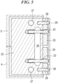
- Fig. 5 illustrates a cross-sectional view taken along line V-V of Fig. 4
- the side surface of the rail 6 is pressed against the reference surface 22b of the base block 22 by use of a cap screw 23 that is threadedly engaged with the base block 22, and a rail retainer 24.
- the rail retainer 24 is placed on the side surface of the rail 6 opposite to the reference surface 22b.
- the rail retainer 24 and a rail retainer 25 include a first rail retainer 24 placed on the side surface of the rail 6 and a second rail retainer 25 placed on the side surface of the rail 7.
- the shank of the cap screw 23 has a threaded portion 23a on the tip side and an unthreaded portion 23b on the head side.
- the female thread portion 22e of the base block 22 is formed with a fall prevention groove 26 having a greater width than the axial length of the threaded portion 23a in such a manner as to divide the female thread portion 22e.
- the base block 22 is provided with guide shafts 28 protruding therefrom by, for example, press fitting.
- the rail retainers 24 and 25 are each formed with a guide hole 29 into which each of the guide shafts 28 fits. Note that the guide shafts may be provided to the rail retainers 24 and 25, and the guide holes may be formed in the base block 22.
- the base block 22 is inserted into the notches 4d and 5d of the rail mounting members 4 and 5.
- the fastening members are passed through the mounting holes 6a and 7a at the ends of the rails 6 and 7, and the ends of the rails 6 and 7 are temporarily fastened to the base block 22 with the fastening members.
- the rails 6 and 7 are pressed against the reference surface 22b of the base block 22 by use of the cap screws 23. At this point in time, the cap screws 23 are tightened with a prescribed torque.
- the temporarily fastened rails 6 and 7 are finally fastened to the base block 22. At this point in time, the fastening members are tightened with a prescribed torque. As described above, the assembly of the rail connecting structure 21 is completed.
- the rail connecting structure of the present embodiment has the following operations and effects.
- the two rails 6 and 7 are placed on and fastened to the top surface 22a of the base block 22. Therefore, the two rails 6 and 7 undergo elastic deformation automatically, and positions thereof are aligned in the up-and-down direction. Hence, it is possible to reduce a level difference in the up-and-down direction at the connecting portion 14 of the rails 6 and 7.
- the two rails 6 and 7 are abutted against the reference surface 22b of the base block 22. Therefore, the two rails 6 and 7 undergo elastic deformation automatically, and the positions thereof are aligned in the left-and-right direction. Hence, it is possible to reduce a level difference in the left-and-right direction at the connecting portion 14 of the rails 6 and 7.
- the base block 22 can move freely relative to the rail mounting members 4 and 5. Accordingly, the misalignment occurring on the rail mounting members 4 and 5 side can be absorbed.
- the side surfaces of the rails 6 and 7 are pressed against the reference surface 22b of the base block 22 by use of the cap screws 23 that are threadedly engaged with the base block 22. Therefore, a level difference in the left-and-right direction at the connecting portion 14 of the rails 6 and 7 can be further reduced.
- the rails 6 and 7 are pressed against the reference surface 22b of the base block 22 by use of the cap screws 23 and the rail retainers 24 and 25. Therefore, as illustrated in Fig. 4 , even if there is no margin for a mounting reference surface height h of the base block 22, the side surfaces of the rails 6 and 7 can be pressed against the reference surface 22b of the base block 22. Note that if the base block 22 has a sufficient mounting reference surface height h, the rail retainers 24 and 25 may be eliminated, and the rails 6 and 7 may be directly pressed with cap screws that are threadedly engaged with the mounting reference surface side.
- the first rail retainer 24 and the second rail retainer 25 are provided. Therefore, even if there is a dimensional difference in the width direction between the two rails 6 and 7, the two rails 6 and 7 can be pressed against the reference surface 22b of the base block 22.
- the fall prevention groove 26 is formed in such a manner as to divide the female thread portion 22e of the base block 22. Therefore, as illustrated in Fig. 4 , even if the cap screw 23 comes out of a female thread portion 22e(1) of the base block 22, the cap screw 23 cannot be engaged with a female thread portion 22e(2) and go in. Hence, it is possible to prevent the cap screw 23 from falling out.
- Fig. 7(a) illustrates a comparative example in which the guide shafts 28 and the guide holes 29 are not provided
- Fig. 7(b) illustrates the present embodiment.
- the base block 22 is provided with the guide shafts 28, and the rail retainers 24 and 25 are formed with the guide holes 29 in which the guide shafts 28 fit. Therefore, it is possible to prevent the rail retainer 24 from moving in the up-and-down direction and rotating as illustrated in Fig. 7(a) .
- the rail retainers 24 and 25 may move by a gap g4 (refer to Fig. 4 ) between the through-hole and the diameter of the cap screw 23, this can be prevented.
- the base block 22 is formed with the step portion 22d. Therefore, the rail retainers 24 and 25 cannot move in the up-and-down direction beyond the step portion 22d. Hence, it is possible to prevent the rail retainers 24 and 25 from falling off.
- the connecting portion 15 of the rail mounting members 4 and 5 and the connecting portion 14 of the rails 6 and 7 are at substantially the same position. Therefore, it is possible to prevent the rails 6 and 7 from coming out of the rail mounting members 4 and 5, and assemblability improves.
- Fig. 8 illustrates another example of a linear motor to which the rail connecting structure 21 of the present embodiment is applied.
- the linear motor of this example includes not only the straight rails 6 and 7 but also curved rails 31 and 32.
- the rail connecting structure 21 of the present embodiment can be applied not only to the connection of the straight rail 6 and the straight rail 7, but also to the connection of the straight rail 7 and the curved rail 31 and of the curved rail 31 and the curved rail 32.
- the reference surface 22b of the base block 22 is formed in a curved shape that is adjusted to the shape of side surfaces of the rails 31 and 32.
- the rail retainers 24 and 25 are also formed in a curved shape that is adjusted to the shape of the side surfaces of the rails 31 and 32.
- the rail connecting structure of the present invention is applied to the linear motor.
- the application of the rail connecting structure of the present invention is not limited to linear motors.
- the rail connecting structure of the present invention can be applied to various apparatuses such as a machine tool, semiconductor manufacturing equipment, and display panel manufacturing equipment in which a carriage and a moving block move along a rail mounted on a rail mounting member.
Landscapes
- Engineering & Computer Science (AREA)
- Mechanical Engineering (AREA)
- General Engineering & Computer Science (AREA)
- Architecture (AREA)
- Civil Engineering (AREA)
- Structural Engineering (AREA)
- Bearings For Parts Moving Linearly (AREA)
- Railway Tracks (AREA)
- Non-Mechanical Conveyors (AREA)
Abstract
Description
- The present invention relates to a rail connecting structure that connects rails to be mounted on rail mounting members.
- Conventionally, when connecting two or more rails, a common method is to provide two reference surfaces (surfaces against which bottom surfaces and side surfaces of the rails abut) on a rail mounting member side, press the two rails against the reference surfaces with a strong force by use of a vise and bolts, and fix the rails without misalignment therebetween. This is because the generation of a level difference at a connecting portion of the rails causes adverse effects on the movement and life of a carriage that moves along the rails. However, this method is based on the premise that the two reference surfaces are formed on one integrated component and there is no mutual error between the reference surfaces against which one rail and the other rail abut.
- On the other hand, in a case of constructing a long path, or in a case of such a product in which rails and rail mounting members are modularized as represented by a linear transport system, not only the rails but also the rail mounting members are separated (refer to Patent Literature 1).
- Patent Literature 1:
JP S63-75202 A - However, when the rail mounting members are separated, the rail mounting members are misaligned at a connecting portion thereof, and thus in the above rail mounting method, a level difference is generated at the connecting portion of the rails that are mounted on the rail mounting members. Even if the rail mounting members are not separated, a level difference is similarly generated at the connecting portion of the rails when mutual error occurs between the reference surfaces of the rail mounting members against which the two rails abut.
- The present invention has been made in view of the above problems, and an object of the present invention is to provide a rail connecting structure capable of absorbing misalignment occurring on rail mounting members side and reducing a level difference generated at a connecting portion of rails.
- In order to solve the above problems, one aspect of the present invention is a rail connecting structure that connects rails to be mounted on rail mounting members, the rail connecting structure including a base block that is placed at a connecting portion of one rail and the other rail and is separate from the rail mounting members, in which the base block is fastened to the one rail and the other rail with fastening members that are passed through mounting holes of the one rail and the other rail, and the base block is not fixed to the rail mounting members and is movable relative to the rail mounting members.
- According to the present invention, it is possible to absorb misalignment occurring on rail mounting members side and reduce a level difference generated at a connecting portion of rails.
-
-
Fig. 1 is a perspective view of a linear motor to which a rail connecting structure of the present embodiment is applied. -
Fig. 2 is an enlarged view of the rail connecting structure of the present embodiment. -
Fig. 3 is an enlarged view of the rail connecting structure of the present embodiment (with one rail removed). -
Fig. 4 is a cross-sectional view taken along line IV-IV ofFig. 2 . -
Fig. 5 is a cross-sectional view taken along line V-V ofFig. 4 . -
Fig. 6(a) is a plan view of the rail connecting structure of the present embodiment (with two rail mounting members misaligned laterally), andFig. 6(b) is a side view of the rail connecting structure of the present embodiment (with the two rail mounting members misaligned vertically). -
Fig. 7(a) illustrates a perspective view of a rail connecting structure of a comparative example in which guide shafts and guide holes are not provided, andFig. 7(b) illustrates a perspective view of the rail connecting structure of the present embodiment. -
Fig. 8 is a perspective view of another example of a linear motor to which the rail connecting structure of the present embodiment is applied. - A rail connecting structure according to an embodiment of the present invention is described in detail hereinafter with reference to the accompanying drawings. However, the rail connecting structure of the present invention can be embodied in various forms and is not limited to the embodiment described in the present description. The present embodiment is provided with the intention of enabling those skilled in the art to fully understand the invention by fully disclosing the description.
-
Fig. 1 illustrates alinear motor 1 to which the rail connecting structure of the present embodiment is applied. Thelinear motor 1 is configured by joining two ormore modules modules rail mounting members rails stators 8 and 9 (for example, coils) of the linear motor. By joining the two ormore modules linear motor 1 can be constructed. - A
reference sign 10 denotes a carriage that travels along therails stators carriage 10. The thrust of thelinear motor 1 acts on thecarriage 10. Travelingbodies 11 and 12 are provided to upper and lower parts of thecarriage 10. Thetraveling bodies 11 and 12 include rollers sandwiching therails traveling bodies 11 and 12, a moving block of a linear guide may be used. - A
rail connecting structure 21 of the present embodiment is described. Since the roller of the traveling body 11 travels, or a rolling element of the moving block rolls, therails rail mounting members rails rail mounting members rail mounting members rails rail mounting members portion 14 of therails rail connecting structure 21 of the present embodiment has a role of absorbing the misalignment occurring on therail mounting members portion 14 of therails - Note that hereinafter, for convenience of description, directions as viewed in a longitudinal direction with the
rails Fig. 1 , are used when the upperrail connecting structure 21 is described. Naturally, the placement of therail connecting structure 21 is not limited thereto. Note that the lowerrail connecting structure 21 is obtained by flipping the upperrail connecting structure 21 vertically. Therefore, the same reference signs are assigned thereto, and a description thereof is omitted. Moreover, in thelinear motor 1, themodules lower rails 6 and a pair of the upper andlower rails 7, respectively, but each of themodules - The
rail mounting members rail mounting members rail mounting members rail mounting members rail mounting members holes 4a through which the fastening members pass. Therail mounting member 4 and therail mounting member 5 are connected together by use of, for example, a positioning pin and a connecting plate. Note that the positioning pin and the connecting plate may be omitted. - The
rails rail mounting members portion 15 of therail mounting members portion 14 of therails holes rails Rolling surfaces traveling bodies 11 and 12 roll are formed on side surfaces of therails rails rail mounting members reference surfaces rails rail mounting members 4 and 5 (refer toFig. 3 ). Therails rail mounting members rails rail mounting members -
Figs. 2 and3 illustrate enlarged views of therail connecting structure 21 of the present embodiment.Fig. 3 illustrates a state in which onerail 6 has been removed. The reference signs 4 and 5 denote the rail mounting members, thereference signs reference sign 22 denotes a base block. - The
base block 22 is placed at the connectingportion 14 of therail 6 and therail 7. Therail mounting members notches base block 22 therein. Therails base block 22 with fastening members such as bolts. Atop surface 22a of thebase block 22 is formed withfemale threads 27 that are threadedly engaged with the fastening members, at positions corresponding to the mountingholes rails base block 22 is formed with areference surface 22b against which side surfaces of therails rails base block 22 with the side surfaces of therails reference surface 22b. Note that although the fastening members are omitted inFigs. 2 and3 , there actually are the fastening members. - The
base block 22 is separate from therail mounting members Fig. 4 )) between thebase block 22 and therail mounting members base block 22 is held only by therails rail mounting members base block 22 can move in the front-and-back, left-and-right, and up-and-down directions relative to therail mounting members Fig. 4 ) may be substantially eliminated to receive the loads of therails base block 22 may be interposed in at least one of the gaps g1 to g3 to dampen vibrations of therails -
Fig. 4 illustrates a cross-sectional view taken along line IV-IV ofFig. 2 , andFig. 5 illustrates a cross-sectional view taken along line V-V ofFig. 4 . In the present embodiment, the side surface of therail 6 is pressed against thereference surface 22b of thebase block 22 by use of acap screw 23 that is threadedly engaged with thebase block 22, and arail retainer 24. Therail retainer 24 is placed on the side surface of therail 6 opposite to thereference surface 22b. As illustrated inFig. 2 , therail retainer 24 and arail retainer 25 include afirst rail retainer 24 placed on the side surface of therail 6 and asecond rail retainer 25 placed on the side surface of therail 7. - As illustrated in
Fig. 4 , thebase block 22 is formed with afemale thread portion 22e that is threadedly engaged with thecap screw 23. The head of thecap screw 23 engages with therail retainer 24. The side surface of therail 6 can be pressed against thereference surface 22b by turning thecap screw 23. - The shank of the
cap screw 23 has a threadedportion 23a on the tip side and an unthreadedportion 23b on the head side. Thefemale thread portion 22e of thebase block 22 is formed with afall prevention groove 26 having a greater width than the axial length of the threadedportion 23a in such a manner as to divide thefemale thread portion 22e. - As illustrated in
Fig. 5 , thebase block 22 is provided withguide shafts 28 protruding therefrom by, for example, press fitting. Therail retainers guide hole 29 into which each of theguide shafts 28 fits. Note that the guide shafts may be provided to therail retainers base block 22. - As illustrated in
Fig. 4 , thebase block 22 is formed with a jutting outportion 22c that protrudes below therail retainers step portion 22d protruding upward is formed at a distal end of the jutting outportion 22c. - An assembly method of the
rail connecting structure 21 of the present embodiment is described. Firstly, therail mounting members rails rails rail mounting members rails rail mounting members - Next, the
base block 22 is inserted into thenotches rail mounting members holes rails rails base block 22 with the fastening members. Next, therails reference surface 22b of thebase block 22 by use of the cap screws 23. At this point in time, the cap screws 23 are tightened with a prescribed torque. Lastly, the temporarily fastenedrails base block 22. At this point in time, the fastening members are tightened with a prescribed torque. As described above, the assembly of therail connecting structure 21 is completed. - The rail connecting structure of the present embodiment has the following operations and effects.
- As illustrated in
Fig. 6(b) , the tworails top surface 22a of thebase block 22. Therefore, the tworails portion 14 of therails Fig. 6(a) , the tworails reference surface 22b of thebase block 22. Therefore, the tworails portion 14 of therails - Even if the
rail mounting members Fig. 6(b) , or even if therail mounting members Fig. 6(a) , thebase block 22 can move freely relative to therail mounting members rail mounting members - There are the gaps g1 to g3 between the
base block 22 and therail mounting members base block 22 is interposed between thebase block 22 and therail mounting members base block 22 can be moved freely relative to therail mounting members - The side surfaces of the
rails reference surface 22b of thebase block 22 by use of the cap screws 23 that are threadedly engaged with thebase block 22. Therefore, a level difference in the left-and-right direction at the connectingportion 14 of therails - The
rails reference surface 22b of thebase block 22 by use of the cap screws 23 and therail retainers Fig. 4 , even if there is no margin for a mounting reference surface height h of thebase block 22, the side surfaces of therails reference surface 22b of thebase block 22. Note that if thebase block 22 has a sufficient mounting reference surface height h, therail retainers rails - The
first rail retainer 24 and thesecond rail retainer 25 are provided. Therefore, even if there is a dimensional difference in the width direction between the tworails rails reference surface 22b of thebase block 22. - The
fall prevention groove 26 is formed in such a manner as to divide thefemale thread portion 22e of thebase block 22. Therefore, as illustrated inFig. 4 , even if thecap screw 23 comes out of afemale thread portion 22e(1) of thebase block 22, thecap screw 23 cannot be engaged with afemale thread portion 22e(2) and go in. Hence, it is possible to prevent thecap screw 23 from falling out. -
Fig. 7(a) illustrates a comparative example in which theguide shafts 28 and the guide holes 29 are not provided, andFig. 7(b) illustrates the present embodiment. Thebase block 22 is provided with theguide shafts 28, and therail retainers guide shafts 28 fit. Therefore, it is possible to prevent therail retainer 24 from moving in the up-and-down direction and rotating as illustrated inFig. 7(a) . Although therail retainers Fig. 4 ) between the through-hole and the diameter of thecap screw 23, this can be prevented. - The
base block 22 is formed with thestep portion 22d. Therefore, therail retainers step portion 22d. Hence, it is possible to prevent therail retainers - The connecting
portion 15 of therail mounting members portion 14 of therails rails rail mounting members -
Fig. 8 illustrates another example of a linear motor to which therail connecting structure 21 of the present embodiment is applied. The linear motor of this example includes not only thestraight rails rails rail connecting structure 21 of the present embodiment can be applied not only to the connection of thestraight rail 6 and thestraight rail 7, but also to the connection of thestraight rail 7 and thecurved rail 31 and of thecurved rail 31 and thecurved rail 32. In this case, thereference surface 22b of thebase block 22 is formed in a curved shape that is adjusted to the shape of side surfaces of therails rail retainers rails - Note that the present invention is not limited to being embodied in the above-described embodiment, and can be embodied in other embodiments to the extent that the gist of the present invention is not changed.
- For example, in the above embodiment, the example in which the rail connecting structure of the present invention is applied to the linear motor is described. However, the application of the rail connecting structure of the present invention is not limited to linear motors. The rail connecting structure of the present invention can be applied to various apparatuses such as a machine tool, semiconductor manufacturing equipment, and display panel manufacturing equipment in which a carriage and a moving block move along a rail mounted on a rail mounting member.
- In the above embodiment, the rail mounting members are separated. However, the rail mounting members may be one integrated component.
- The present description is based on
Japanese Patent Application No. 2022-020928 filed on February 15, 2022 -
- 4, 5 Rail mounting member
- 6, 7 Rail
- 6a, 7a Mounting hole of rail
- 14 Connecting portion of rails
- 15 Connecting portion of rail mounting members
- 21 Rail connecting structure
- 22 Base block
- 22b Reference surface of base block
- 22e Female thread of base block
- 23 Cap screw
- 23a Threaded portion of cap screw
- 23b Unthreaded portion of cap screw
- 24 First rail retainer (rail retainer)
- 25 Second rail retainer (rail retainer)
- 26 Fall prevention groove of base block
- 28 Guide shaft
- 29 Guide hole
- g1 to g3 Gap
Claims (6)
- A rail connecting structure that connects rails to be mounted on rail mounting members, the rail connecting structure comprisinga base block that is placed at a connecting portion of one rail and the other rail and is separate from the rail mounting members, whereinthe base block is fastened to the one rail and the other rail with fastening members that are passed through mounting holes of the one rail and the other rail, andthe base block is not fixed to the rail mounting members and is movable relative to the rail mounting members.
- The rail connecting structure according to claim 1, wherein there is a gap between the base block and the rail mounting members, or an interposed object that allows movement of the base block is interposed between the base block and the rail mounting members.
- The rail connecting structure according to claim 1 or 2, wherein side surfaces of the rails are pressed against a reference surface of the base block by use of cap screws that are threadedly engaged with the base block.
- The rail connecting structure according to claim 3, wherein the side surfaces of the rails are pressed against the reference surface of the base block by use of the cap screws and rail retainers placed on side surfaces of the rails opposite to the reference surface.
- The rail connecting structure according to claim 4, whereina shank of each of the cap screws has a threaded portion on a tip side thereof and an unthreaded portion on a head side thereof, anda female thread portion of the base block is formed with a fall prevention groove having a greater width than an axial length of the threaded portion in such a manner as to divide the female threaded portion.
- The rail connecting structure according to any one of claims 1 to 5, whereinthe one rail is mounted on one rail mounting member, andthe other rail is mounted on the other rail mounting member.
Applications Claiming Priority (2)
| Application Number | Priority Date | Filing Date | Title |
|---|---|---|---|
| JP2022020928A JP7785558B2 (en) | 2022-02-15 | 2022-02-15 | Rail connection structure |
| PCT/JP2023/001464 WO2023157546A1 (en) | 2022-02-15 | 2023-01-19 | Rail connection structure |
Publications (2)
| Publication Number | Publication Date |
|---|---|
| EP4480869A1 true EP4480869A1 (en) | 2024-12-25 |
| EP4480869A4 EP4480869A4 (en) | 2026-06-24 |
Family
ID=87578312
Family Applications (1)
| Application Number | Title | Priority Date | Filing Date |
|---|---|---|---|
| EP23756074.3A Pending EP4480869A4 (en) | 2022-02-15 | 2023-01-19 | RAIL CONNECTION STRUCTURE |
Country Status (6)
| Country | Link |
|---|---|
| US (1) | US20250154730A1 (en) |
| EP (1) | EP4480869A4 (en) |
| JP (1) | JP7785558B2 (en) |
| KR (1) | KR20240149948A (en) |
| CN (1) | CN118632958A (en) |
| WO (1) | WO2023157546A1 (en) |
Families Citing this family (1)
| Publication number | Priority date | Publication date | Assignee | Title |
|---|---|---|---|---|
| EP4553016A1 (en) * | 2023-11-08 | 2025-05-14 | Robert Bosch GmbH | Track module for a linear motor conveying system, track system, linear motor convey-ing system and corresponding methods |
Family Cites Families (12)
| Publication number | Priority date | Publication date | Assignee | Title |
|---|---|---|---|---|
| JPH066801B2 (en) | 1986-09-13 | 1994-01-26 | 日立機電工業株式会社 | Traveling rails for conveyors using linear motors |
| JP2000312463A (en) * | 1999-04-27 | 2000-11-07 | Shinko Electric Co Ltd | Rail connection structure for linear motor |
| JP4266566B2 (en) * | 2002-03-20 | 2009-05-20 | 株式会社デジタル | Rail mounting mechanism |
| JP2010265627A (en) * | 2009-05-13 | 2010-11-25 | Mitsubishi Heavy Ind Ltd | Sleeper fastening structure of magnetic levitation system |
| JP5567459B2 (en) * | 2010-10-07 | 2014-08-06 | ヤマハ発動機株式会社 | Connecting structure of linear motor type conveyor |
| DE102016107139B4 (en) * | 2016-04-18 | 2017-11-30 | Hiwin Technologies Corp. | Threadless linear rail |
| US11117757B2 (en) * | 2016-09-21 | 2021-09-14 | Yamaha Hatsudoki Kabushiki Kaisha | Linear conveyor device |
| PL3612677T3 (en) * | 2017-04-19 | 2023-04-11 | Sika Technology Ag | System for fastening a rail, methods for producing a fastening and a support system for a rail and use of a rail fastening system |
| EP3771665A1 (en) * | 2019-07-31 | 2021-02-03 | ATS Automation Tooling Systems Inc. | Adaptive joint connector system and method for connecting conveyor track |
| JP2022020928A (en) | 2020-07-21 | 2022-02-02 | 文隆 石垣 | Flame-retardant material and combustion device |
| CN213538566U (en) * | 2020-09-27 | 2021-06-25 | 南京北路智控科技股份有限公司 | Track mechanism |
| CN214245150U (en) * | 2020-12-14 | 2021-09-21 | 江苏飞梭智行设备有限公司 | Track capable of automatically compensating track joint |
-
2022
- 2022-02-15 JP JP2022020928A patent/JP7785558B2/en active Active
-
2023
- 2023-01-19 KR KR1020247030556A patent/KR20240149948A/en active Pending
- 2023-01-19 WO PCT/JP2023/001464 patent/WO2023157546A1/en not_active Ceased
- 2023-01-19 EP EP23756074.3A patent/EP4480869A4/en active Pending
- 2023-01-19 CN CN202380018903.XA patent/CN118632958A/en active Pending
- 2023-01-19 US US18/838,440 patent/US20250154730A1/en active Pending
Also Published As
| Publication number | Publication date |
|---|---|
| EP4480869A4 (en) | 2026-06-24 |
| JP2023118152A (en) | 2023-08-25 |
| KR20240149948A (en) | 2024-10-15 |
| JP7785558B2 (en) | 2025-12-15 |
| US20250154730A1 (en) | 2025-05-15 |
| WO2023157546A1 (en) | 2023-08-24 |
| CN118632958A (en) | 2024-09-10 |
Similar Documents
| Publication | Publication Date | Title |
|---|---|---|
| KR101758288B1 (en) | Carriage support unit and Robot carriage | |
| US5273381A (en) | Ball screw guide unit and transporting table using the same | |
| DE69409679T2 (en) | Guide unit for linear movements | |
| US20250154730A1 (en) | Rail connecting structure | |
| EP3597471A1 (en) | Linear motor with guideway stator | |
| KR100865000B1 (en) | Linear motion guide unit | |
| US11619262B2 (en) | Linear motion guide unit | |
| JPH08247142A (en) | Linear motion rolling guide unit | |
| DE112020007075B4 (en) | Conveyor table transfer device, transport system and conveyor table transfer method | |
| JPH07124831A (en) | Linear guide device | |
| JP2565426Y2 (en) | Linear motion rolling guide unit | |
| KR20240112892A (en) | guidance device | |
| DE69717663T2 (en) | CARTESIAN TYPE ROBOT | |
| US20230120759A1 (en) | Machine Frame For A Machine Tool and Machine Tool | |
| EP1363036A2 (en) | Linear motion guide unit | |
| US10018226B2 (en) | Linear motion guide unit | |
| JP2006080260A (en) | Guide mechanism and work transfer device | |
| JP3093858B2 (en) | Table equipment | |
| JPH0630527U (en) | Linear motion rolling guide unit | |
| JP4562140B2 (en) | Linear motion guide unit with connecting track rail | |
| CN117585381A (en) | track | |
| US5393144A (en) | Linear motion guide unit | |
| JP2575926B2 (en) | Linear guide device | |
| CN221363668U (en) | Guide rail assembly, motion platform and processing equipment | |
| JP7863175B2 (en) | Slide member and component mounting machine |
Legal Events
| Date | Code | Title | Description |
|---|---|---|---|
| STAA | Information on the status of an ep patent application or granted ep patent |
Free format text: STATUS: THE INTERNATIONAL PUBLICATION HAS BEEN MADE |
|
| PUAI | Public reference made under article 153(3) epc to a published international application that has entered the european phase |
Free format text: ORIGINAL CODE: 0009012 |
|
| STAA | Information on the status of an ep patent application or granted ep patent |
Free format text: STATUS: REQUEST FOR EXAMINATION WAS MADE |
|
| 17P | Request for examination filed |
Effective date: 20240801 |
|
| AK | Designated contracting states |
Kind code of ref document: A1 Designated state(s): AL AT BE BG CH CY CZ DE DK EE ES FI FR GB GR HR HU IE IS IT LI LT LU LV MC ME MK MT NL NO PL PT RO RS SE SI SK SM TR |
|
| DAV | Request for validation of the european patent (deleted) | ||
| DAX | Request for extension of the european patent (deleted) | ||
| REG | Reference to a national code |
Ref country code: DE Ref legal event code: R079 Free format text: PREVIOUS MAIN CLASS: B65G0054020000 Ipc: F16C0029000000 |
|
| A4 | Supplementary search report drawn up and despatched |
Effective date: 20260521 |
|
| RIC1 | Information provided on ipc code assigned before grant |
Ipc: F16C 29/00 20060101AFI20260515BHEP Ipc: B65G 54/02 20060101ALI20260515BHEP |