EP4480847A1 - Double container, method for attaching refill in double container, and connecting parts - Google Patents
Double container, method for attaching refill in double container, and connecting parts Download PDFInfo
- Publication number
- EP4480847A1 EP4480847A1 EP23756262.4A EP23756262A EP4480847A1 EP 4480847 A1 EP4480847 A1 EP 4480847A1 EP 23756262 A EP23756262 A EP 23756262A EP 4480847 A1 EP4480847 A1 EP 4480847A1
- Authority
- EP
- European Patent Office
- Prior art keywords
- container
- connecting member
- inner container
- mouth part
- tube
- Prior art date
- Legal status (The legal status is an assumption and is not a legal conclusion. Google has not performed a legal analysis and makes no representation as to the accuracy of the status listed.)
- Withdrawn
Links
Images






Classifications
-
- B—PERFORMING OPERATIONS; TRANSPORTING
- B05—SPRAYING OR ATOMISING IN GENERAL; APPLYING FLUENT MATERIALS TO SURFACES, IN GENERAL
- B05B—SPRAYING APPARATUS; ATOMISING APPARATUS; NOZZLES
- B05B11/00—Single-unit hand-held apparatus in which flow of contents is produced by the muscular force of the operator at the moment of use
- B05B11/0005—Components or details
- B05B11/0037—Containers
- B05B11/0038—Inner container disposed in an outer shell or outer casing
-
- B—PERFORMING OPERATIONS; TRANSPORTING
- B65—CONVEYING; PACKING; STORING; HANDLING THIN OR FILAMENTARY MATERIAL
- B65D—CONTAINERS FOR STORAGE OR TRANSPORT OF ARTICLES OR MATERIALS, e.g. BAGS, BARRELS, BOTTLES, BOXES, CANS, CARTONS, CRATES, DRUMS, JARS, TANKS, HOPPERS, FORWARDING CONTAINERS; ACCESSORIES, CLOSURES, OR FITTINGS THEREFOR; PACKAGING ELEMENTS; PACKAGES
- B65D77/00—Packages formed by enclosing articles or materials in preformed containers, e.g. boxes, cartons, sacks or bags
- B65D77/04—Articles or materials enclosed in two or more containers disposed one within another
- B65D77/048—Articles or materials enclosed in two or more containers disposed one within another the inner and outer containers being rigid and the outer container being of curved cross-section, e.g. cylindrical
- B65D77/0486—Articles or materials enclosed in two or more containers disposed one within another the inner and outer containers being rigid and the outer container being of curved cross-section, e.g. cylindrical the inner container being coaxially disposed within the outer container
- B65D77/0493—Articles or materials enclosed in two or more containers disposed one within another the inner and outer containers being rigid and the outer container being of curved cross-section, e.g. cylindrical the inner container being coaxially disposed within the outer container and retained at a distance of the inner side-wall of the outer container, e.g. within a bottle neck
-
- B—PERFORMING OPERATIONS; TRANSPORTING
- B05—SPRAYING OR ATOMISING IN GENERAL; APPLYING FLUENT MATERIALS TO SURFACES, IN GENERAL
- B05B—SPRAYING APPARATUS; ATOMISING APPARATUS; NOZZLES
- B05B11/00—Single-unit hand-held apparatus in which flow of contents is produced by the muscular force of the operator at the moment of use
- B05B11/0005—Components or details
- B05B11/0037—Containers
- B05B11/0054—Cartridges, i.e. containers specially designed for easy attachment to or easy removal from the rest of the sprayer
-
- B—PERFORMING OPERATIONS; TRANSPORTING
- B05—SPRAYING OR ATOMISING IN GENERAL; APPLYING FLUENT MATERIALS TO SURFACES, IN GENERAL
- B05B—SPRAYING APPARATUS; ATOMISING APPARATUS; NOZZLES
- B05B11/00—Single-unit hand-held apparatus in which flow of contents is produced by the muscular force of the operator at the moment of use
- B05B11/01—Single-unit hand-held apparatus in which flow of contents is produced by the muscular force of the operator at the moment of use characterised by the means producing the flow
- B05B11/10—Pump arrangements for transferring the contents from the container to a pump chamber by a sucking effect and forcing the contents out through the dispensing nozzle
- B05B11/1042—Components or details
- B05B11/1043—Sealing or attachment arrangements between pump and container
- B05B11/1046—Sealing or attachment arrangements between pump and container the pump chamber being arranged substantially coaxially to the neck of the container
- B05B11/1047—Sealing or attachment arrangements between pump and container the pump chamber being arranged substantially coaxially to the neck of the container the pump being preassembled as an independent unit before being mounted on the container
-
- B—PERFORMING OPERATIONS; TRANSPORTING
- B65—CONVEYING; PACKING; STORING; HANDLING THIN OR FILAMENTARY MATERIAL
- B65D—CONTAINERS FOR STORAGE OR TRANSPORT OF ARTICLES OR MATERIALS, e.g. BAGS, BARRELS, BOTTLES, BOXES, CANS, CARTONS, CRATES, DRUMS, JARS, TANKS, HOPPERS, FORWARDING CONTAINERS; ACCESSORIES, CLOSURES, OR FITTINGS THEREFOR; PACKAGING ELEMENTS; PACKAGES
- B65D83/00—Containers or packages with special means for dispensing contents
- B65D83/771—Containers or packages with special means for dispensing contents for dispensing fluent contents by means of a flexible bag or a deformable membrane or diaphragm
Definitions
- the present invention relates to a double container, a method for attaching a refill in a double container, and a connecting part used for connecting the double container.
- containers for various applications have been increasingly reduced in thickness or have been being formed in a film shape.
- inner containers reduced in thickness alone cannot help reduction in the content and cannot keep themselves self-standing, double containers in which inner containers (refill containers) reduced in thickness and outer containers that can be used repeatedly are combined are being popularized.
- PTL 1 discloses a configuration including an outer cap 83 configured to be screw-threadedly engaged with the upper end of the side wall of a tubular outer container 82 while pressing a flange 811 of an inner container 81 from above, to thereby facilitate engagement between the inner container 81 and the outer container 82.
- pressing the flange 811 from above is the only action that is applied by the outer cap 83 to the inner container 81. Therefore, when removing a mouth cap 85, which is a pumping outlet through which a pump mechanism 84 is inserted, by rotating the mouth cap relative to the inner container 81, the inner container 81 may rotate conjunctively with the mouth cap 85 and the mouth cap 85 may not loosen open, if the outer container 82 is held in a grasping manner.
- PTL 2 discloses a technique relating to a double container, in which an inner container 90 includes above a containing part 91, a fit-in tube 92 as an outwardly overhanging integrated part, wherein the fit-in tube has a bend part 93 configured to inhibit conjunctive rotation of the inner container 90 and a cap 99 that is engaged with a mouth part 94.
- a double container can inhibit conjunctive rotation of a cap and an inner container while minimizing the amount of resins used in the refill inner container.
- the present invention relates to a double container, a method for attaching a refill in a double container, and a connecting part included in the double container.
- An inner container of the double container is a container made of a resin or paper, and may be a self-standing type or a non-self-standing type.
- An outer container of the double container is a self-standing container made of glass, wood, resin, silicon, metal, and the like.
- the content to be contained in the inner container held by the outer container of the double container according to the present invention is a liquid or powder substance that is used dividedly in several portions such as a cosmetic material, a fragrance, a detergent, a seasoning, and the like, rather than something that is for one-time serving.
- a double container 100 includes an inner container 1, an outer container 2, and a connecting part 3 as main parts.
- the connecting part 3 includes two parts, namely a first connecting member 4 and a second connecting member 5.
- the double container 100 also includes an inner plug 6 and a cap 7 as accessory parts.
- the inner container 1 includes a bottle body 10 for containing a content and a mouth part 14.
- the bottle body (also referred to as a bottle part or a containing part) 10 has a bottomed tube shape having a bottom 11 and a trunk 12, and has a shoulder part 13 having a center hole O1 in the center of the upper surface.
- the mouth part 14 of the inner container 1 is a standing tubular part standing upright on the rim of the center hole O1 formed in the shoulder part 13 of the bottle body 10.
- the inner container 1 is made of, for example, a resin or paper.
- the resin of which the inner container 1 is made is composed of, for example, polypropylene (PP), polyethylene (PE), acrylonitrile-butadiene-styrene (ABS), polybutylene terephthalate (PBS), polyacetal (POM), polyester-based resins such as polyethylene terephthalate (PET), biodegradable resins, and the like.
- the paper of which the inner container 1 is made is, for example, a laminate using paper as a base material.
- the outer container 2 is a bottomed tube-shaped self-standing container with an opening O4 formed at the upper end, wherein the outer container is configured to accommodate the inner container 1 in a replaceable manner, and serves as an outer container that is on the outer side in the double container 100.
- the outer container 2 has a bottom 21 and a side wall (outer wall) 22.
- the side wall 22 includes an upper-end thin side wall 23 at the upper end thereof.
- the upper-end thin side wall 23 has screw threads 24 on the outer surface thereof, and has a jagged surface 25, in which a plurality of indentations extending in the longitudinal direction are formed, on the inner surface thereof.
- the inner jagged surface 25 is a rotation restricting part of the outer container 2.
- the outer container 2 of the present invention is made of, for example, resin, glass, wood, silicon, metal, paper, and the like.
- the outer container 2 is made of, for example, resin such as PP, PE, ABS, PBS, POM, PET, or polyester-based resins, biodegradable resins, and the like, similarly to the inner container 1 described above.
- resin such as PP, PE, ABS, PBS, POM, PET, or polyester-based resins, biodegradable resins, and the like, similarly to the inner container 1 described above.
- Examples of wood include: wood of needle-leaf trees such as cedar, cypress, pine, and the like; wood of broad-leaf trees such as oak, walnut, black cherry, alder, rubberwood, and the like; and bamboo.
- An example of paper is self-standing cardboard.
- the first connecting member 4 of the connecting part 3 is a two-stage tube-shaped member and has an opening O3 that is larger than the outer diameter of the mouth part 14 and through which the mouth part of the inner container can be inserted. As illustrated in FIG. 3 , the first connecting member 4 is a cover member configured to be threadedly engaged with the outer surface of the side wall 22 of the outer container 2 while covering the shoulder part 13 of the inner container 1.
- the second connecting member 5 of the connecting part 3 is an approximately tube-shaped rotation restricting member that has an opening O2, through which an upper part of the mouth part 14 of the inner container 1 is inserted, and that is situated on the inner side of the first connecting member 4.
- the second connecting member 5 can be engaged with the first connecting member 4 while being restricted from rotation relative to it.
- the second connecting member 5 can also be engaged with a part of the mouth part 14 of the inner container 1 while being restricted from rotation relative to it.
- the first connecting member 4 and the second connecting member 5 are made of resin such as, for example, PP, PE, ABS, PBS, POM, PET, or polyester-based resins, biodegradable resins, and the like.
- the inner plug 6 is a discharge amount adjusting part that is attached in the center hole O1 of the mouth part 14 of the inner container 1, and in which a discharge port for discharging the content in an adequate amount is formed.
- the inner plug 6 is made of, for example, elastic rubber or resin (for example, PP, PE) .
- the cap 7 is a capping part of the inner container 1, and is configured to cover the upper part and the circumference of the mouth part 14 of the inner container 1.
- the cap 7 is made of, for example, resin such as PP, PE, ABS, PBS, POM, PET, or polyester-based resins, a biodegradable resin, and the like.
- FIG. 5 is an oblique exploded bottom view of the connecting part 3.
- FIG. 6 is a cross-sectional view of the connecting part 3. The configuration of the connecting part will be described with reference to FIGS. 4 to 6 .
- the first connecting member 4 has an outer tube 41, an outer annular plate 43, an upright tube 44, and an upper-end ring 45.
- the first connecting member 4 has a two-stage tube shape including: the outer tube 41 having a larger diameter; and the upright tube 44 having a smaller diameter.
- the outer tube 41 is an outer tubular part that can be threadedly engaged with the outer container 2, and screw threads 42 are provided on the inner circumferential surface of the outer tube 41.
- the screw threads 42 of the outer tube 41 are threadedly engaged with the screw threads 24 of the outer container 2.
- an annular projection 46 is provided on the inner circumferential surface of the outer tube 41 above the screw threads 42.
- a portion sandwiched between the annular projection 46 and the lower surface of the outer annular plate 43 at the upper end of the inner circumferential surface of the outer tube 41 is a fitting groove 47 (see FIG. 6 ).
- the outer annular plate 43 is an annular plate extending inward from the upper end of the outer tube 41 so as to reduce the diameter of the outer tube.
- the upright tube 44 stands upright on the inner rim of the outer annular plate 43.
- the upper-end ring 45 is a small-diameter upper-end annular plate extending inward from the upper end of the upright tube 44 so as to reduce the diameter of the upright tube.
- the second connecting member 5 includes a fit-in tube 51, an annular support plate 53, an upright tube 54, an upper-end diameter-reducing ring 56, and a plurality of locking hooks 58.
- Outer ribs 52 are formed on the outer circumferential surface of the fit-in tube 51.
- a plurality of inner ribs 57 are provided on the inner circumferential surface of the upright tube 54 under the upper-end diameter-reducing ring 56.
- the upright tube 54 stands upright on the inner rim of the annular support plate 53, which is an annular plate, and the fit-in tube 51 is suspended from the lower surface of the annular support plate 53 at a position that is slightly on the inner side of the outer rim of the annular support plate.
- the outer rim of the annular support plate 53 is located on the outer side of the upper end of the fit-in tube 51.
- Regions of the upright tube 54 that face the locking hooks 58 are arc-shaped diameter-increasing regions 55 located at positions that are more outward than the remaining regions of the upright tube.
- the upper-end diameter-reducing ring 56 is a small-diameter upper-end annular plate extending inward from the upper end of the upright tube 54 and from the upper ends of the diameter-increasing regions 55 so as to reduce their diameters.
- the plurality of linear outer ribs 52 provided on the outer surface of the lower fit-in tube 51 of the second connecting member 5 are an outer-circumference rotation restricting part configured to restrict rotation relative to the outer container 2.
- the inner ribs 57 provided on the inner surface of the upper upright tube 54 are an inner-circumference rotation restricting part configured to restrict rotation relative to the inner container 1, and include a plurality of plate-shaped ribs.
- the inner-circumference rotation restricting part and the outer-circumference rotation restricting part of the second connecting member 5 may be structured in other forms, and, for example, different numbers of linear ribs may be provided, or the inner surface or the outer surface may have a polygonal cross-sectional shape.
- the locking hooks 58 are elastic engaging pieces that are suspended in a cantilever-like manner from the inner rim of the upper-end diameter-reducing ring 56, which constitutes the upper end, and have an outward spring property.
- the locking hooks 58 each include an extending part 581 that extends in the vertical direction, and a locking projection 582 that is provided about the lower end of the inner surface of the extending part 581 and projects inward.
- the plurality of locking hooks 58 are provided in the circumferential direction.
- FIGS. 4 and 5 illustrate an example in which three locking hooks 58 are provided, but the locking hooks 58 may be provided in any plural number.
- FIG. 7 is an oblique view of the mouth part 14 of the inner container 1 and its surroundings.
- the outer circumferential surface of the tubular mouth part 14 of the inner container 1 is provided with a lower flange 15, an upper flange 16, a plurality of plate-shaped ribs 17 and 18, and screw threads 19 (see FIG. 4 ) .
- the lower flange 15 and the upper flange 16 are annular members extending outward from the outer circumferential surface of the mouth part 14.
- the outer diameter of the outer rim of the lower flange 15 is larger than that of the upper flange 16.
- the plurality of plate-shaped ribs 17 and 18 are plate-shaped ribs that are continuous in the vertical direction so as to be continuously joined with the lower flange 15 and the upper flange 16, and provided so as to extend outward from the outer circumferential surface of the mouth part 14.
- the lower one is the lower rib 17 projecting long
- the upper one is the upper rib 18 projecting short.
- the upper rib 18 extends outward by the same length as the upper flange 16, and the lower rib 17 extends outward slightly shorter than the lower flange 15 and longer than the upper rib 18, such that the upper rib 18 and the lower rib 17 are bounded as a step.
- the upper end of the lower rib 17, which constitutes the step, is a rib top 17U.
- the lower flange 15 and the rib top 17U of the lower rib 17 function as a position restricting part.
- the lower rib 17 is a mouth part rotation restricting part of the inner container 1, and is configured to contact the inner ribs 57 of the second connecting member 5 to restrict rotation of the inner container 1 and the second connecting member 5 relative to each other.
- the upper flange 16 is an intrusion inhibiting member configured to inhibit the content from intruding into the connecting part 3, and the upper rib 18 is a member configured to adjust the connecting part 3 so as not to be inclined in the thickness direction during assembly.
- the upper end of the side wall 22 is the upper-end thin side wall 23 reduced on the outer side, and the upper-end thin side wall 23 is provided with the screw threads 24 on the outer surface, and with the jagged surface 25 on the inner circumferential surface, recesses and projections extending in the longitudinal direction being repeatedly provided in the jagged surface.
- the jagged surface 25 is a rotation restricting part of the outer container 2.
- the rotation restricting part provided on the inner surface of the outer container 2 may be structured in any other form, and, for example, liner ribs or liner slits may be provided in a less number, or the top-view shape may be a polygonal shape.
- FIG. 9 is an enlarged cross-sectional view of the mouth part of the double container 100 of the present invention and its surroundings.
- FIG. 9 is an enlarged view of the region X denoted by the dashed line in FIG. 3 .
- FIG. 10 is a cross-sectional view illustrating engagement between the inner container 1 and the connecting part 3, and is a cross-sectional view along the surface A illustrated in FIGS. 3 and 9 .
- FIG. 11 is a cross-sectional view illustrating engagement between the outer container 2 and the connecting part 3, and is a cross-sectional view along the surface B illustrated in FIGS. 3 and 9 .
- the engagement is established such that the upper surface of the upper-end ring 45 of the first connecting member 4 is positioned substantially on the same plane as the upper surface of the upper flange 16 of the mouth part 14 of the inner container 1.
- the upper-end ring 45 of the first connecting member 4 and the upper-end diameter-reducing ring 56 of the second connecting member 5 are positioned so as to overlap the rib top 17U, which is the step of the mouth part 14.
- the inner rim of the upper-end ring 45 faces the outer rim of the upper flange 16, and the inner rim of the upper-end diameter-reducing ring 56 faces the outer end of the upper rib 18.
- the user can use the assembled double container 100 without any discomfort because there are few recesses or projections exposed to the outside.
- the outer ribs 52 of the fit-in tube 51 of the second connecting member 5 are engaged while being fitted in the recesses in the jagged surface 25 on the inner side of the upper-end thin side wall 23 of the outer container 2.
- the second connecting member 5 is engaged with the outer container 2 while being restricted from rotation relative to it.
- screw threads 72 are formed on the inner surface of a circumferential wall 71 of the cap 7, and the cap 7 is attachable to the inner container 1 by being threadedly engaged with the screw threads 19 formed on the outer circumferential surface of the inner container 1 above the mouth part 14.
- the inner container 1 does not rotate relative to the outer container 2. That is, with the double container 100, conjunctive rotation of the cap 7 and the inner container 1 can be inhibited when the cap 7 is opened or closed.
- FIG. 12 is a flowchart of the replacement of refills in the double container of the present invention.
- FIG. 13 is a view illustrating removal of a connecting part-attached inner container ⁇ from the outer container 2.
- FIG. 14 is a cross-sectional view illustrating removal of the connecting part 3 of the present invention from the inner container 1.
- FIG. 15 is a cross-sectional view illustrating attaching of the connecting part 3 of the present invention to the inner container 1.
- the first connecting member 4 and the second connecting member 5 are previously engaged as a state before being put on sale, and the connecting part 3 is in a disassemblable state.
- the connecting part 3 When replacing the current inner container with a new refill since the content has decreased, the connecting part 3 is first rotated relative to the outer container 2 in the step S1 to free the connecting part 3 and the outer container 2 from threaded engagement (i.e., to free the screw threads 42 of the first connecting member 4 and the screw threads 24 of the outer container 2 from engagement).
- step S2 the connecting part 3 is lifted to remove the connecting part-attached inner container ⁇ from the outer container 2.
- the state in the step S2 is illustrated in FIG. 13 .
- the connecting part 3 is pushed upward with a force applied to a part thereof, to free the locking hooks 58 of the connecting part 3 from engagement with the position restricting part (lower flange 15) of the inner container, one by one.
- the state in the step S3 is illustrated in FIG. 14 . Since the locking hooks 58 are elastically deformable outward, as illustrated in FIG. 14 , disengagement of one of the locking hooks 58 from the lower flange 15 by application of the force to the part of the connecting part 3 causes the other locking hooks 58 to be disengaged one after another.
- step S4 the connecting part 3 is lifted and removed from the inner container 1 having no remaining content or a low remaining content.
- step S5 while covering an inner container 1 (cap-attached inner container), which is a substituted refill, with the connecting part 3 from above the inner container, the mouth part 14 of the substituted inner container 1 is inserted through the openings O2 and O3 of the connecting part 3.
- step S5 in the state in which the mouth part 14 of the substituted inner container 1 is inserted into the openings O2 and O3 of the connecting part 3, the locking hooks 58 and the lower flange 15 of the inner container 1 are engaged, to thereby engage the connecting part 3 and the inner container 1.
- step S6 in the state in which the mouth part 14 of the inner container 1 is inserted into the openings O2 and O3 of the connecting part 3, the connecting part 3 is pushed downward to engage the locking hooks 58 and the lower flange 15 of the inner container 1. As a result, the connecting part 3 and the inner container 1 are engaged.
- step S7 while covering the outer container 2 with the connecting part 3 of the connecting part-attached refill container, the upper-end thin side wall 23 of the outer container 2 is fitted between the outer-side outer tube 41 and the inner-side fit-in tube 51 of the connecting part 3.
- step S8 the screw threads 42 of the first connecting member 4 and the screw threads 24 of the outer container 2 are threadedly engaged to complete the engagement between the inner container 1 and the outer container 2 via the connecting part 3.
- a force is applied upward to a part of the connecting part 3 as illustrated in FIG. 14 .
- a locking hook 58 on the side where no force is applied deforms to be kept engaged with the lower flange 15, while one locking hook 58 on the side where the force is applied is disengaged from the lower flange 15, thereby freeing the locking hooks 58 from the engaged state in order. In this way, the connecting part 3 is removed.
- the inner container can serve as a refill that can be replaced, together with its content, with respect not only to the outer container but also to the connecting part made of the first connecting member and the second connecting member.
- the connecting part can also be removed from the inner container and reused repeatedly together with the outer container. Therefore, there are more parts that can be reused, and it is possible to reduce resin loss. Therefore, the double container according to the present invention can inhibit conjunctive rotation of the cap and the inner container while minimizing the amount of resins used in the refill inner container.
Landscapes
- Engineering & Computer Science (AREA)
- Mechanical Engineering (AREA)
- Packages (AREA)
- Rigid Containers With Two Or More Constituent Elements (AREA)
Abstract
Description
- The present invention relates to a double container, a method for attaching a refill in a double container, and a connecting part used for connecting the double container.
- In recent years, from the viewpoint of reducing resins used as container materials, containers for various applications have been increasingly reduced in thickness or have been being formed in a film shape. However, since inner containers reduced in thickness alone cannot help reduction in the content and cannot keep themselves self-standing, double containers in which inner containers (refill containers) reduced in thickness and outer containers that can be used repeatedly are combined are being popularized.
- As an example of such a double container,
PTL 1 discloses a configuration including anouter cap 83 configured to be screw-threadedly engaged with the upper end of the side wall of a tubularouter container 82 while pressing aflange 811 of aninner container 81 from above, to thereby facilitate engagement between theinner container 81 and theouter container 82. - However, according to the configuration of
PTL 1, pressing theflange 811 from above is the only action that is applied by theouter cap 83 to theinner container 81. Therefore, when removing amouth cap 85, which is a pumping outlet through which apump mechanism 84 is inserted, by rotating the mouth cap relative to theinner container 81, theinner container 81 may rotate conjunctively with themouth cap 85 and themouth cap 85 may not loosen open, if theouter container 82 is held in a grasping manner. - As illustrated in
FIG. 2 ,PTL 2 discloses a technique relating to a double container, in which aninner container 90 includes above a containingpart 91, a fit-intube 92 as an outwardly overhanging integrated part, wherein the fit-in tube has abend part 93 configured to inhibit conjunctive rotation of theinner container 90 and acap 99 that is engaged with amouth part 94. -
- [PTL 1]
Japanese Utility Model Application Laid-Open Publication No. H5-075163 - [PTL 2]
Japanese Patent Application Laid-Open Publication No. 2008-87768 - Here, in a double container in which an inner container is prepared as a refill, an inner container is replaced with a new inner container (refill container) and discarded when its content is used up, whereas the outer container is repeatedly used. When the inner container includes, as an integrated part, a fit-in
tube 92 having a bend part as inPTL 2, the amount of refill-side resin that is discarded without being repeatedly used after the content is exhausted increases. - In view of the above circumstances, an object of the present invention is to provide a double container that can inhibit conjunctive rotation of an inner container and a cap, while minimizing the amount of resins used in a refill inner container.
- In order to solve the above problems, one aspect of the present invention provides a double container, including:
- an inner container including a mouth part and a shoulder part;
- an outer container having a side wall, the outer container being configured to accommodate the inner container in a replaceable manner;
- a first connecting member having a two-stage tube shape, the first connecting member having an opening through which the mouth part of the inner container can be inserted, and the first connecting member being configured to be threadedly engaged with an outer surface of the side wall of the outer container while covering the shoulder part of the inner container and an upper end of the side wall; and
- a second connecting member having an approximately tube shape, the second connecting member having an opening through which the mouth part of the inner container can be inserted, and the second connecting member being situated on an inner side of the first connecting member,
- wherein the second connecting member includes:
- an inner-circumference rotation restricting part configured to contact a part of the mouth part of the inner container to restrict rotation relative to the mouth part; and
- an outer-circumference rotation restricting part configured to contact a part of the side wall of the outer container to restrict rotation relative to the outer container, and
- in an assembled state, the inner container is restricted from rotation relative to the outer container.
- According to one aspect, a double container can inhibit conjunctive rotation of a cap and an inner container while minimizing the amount of resins used in the refill inner container.
-
- [
FIG. 1] FIG. 1 is a cross-sectional view of the double container according toRelated Art 1. - [
FIG. 2] FIG. 2 is a half cross-sectional view of the inner container of the double container according toRelated Art 2. - [
FIG. 3] FIG. 3 is a half cross-sectional view of a double container according to an embodiment of the present invention. - [
FIG. 4] FIG. 4 is an exploded view of the double container ofFIG. 2 . - [
FIG. 5] FIG. 5 is an oblique exploded bottom view of a connecting part. - [
FIG. 6] FIG. 6 is a cross-sectional view of the connecting part. - [
FIG. 7] FIG. 7 is an oblique view of a mouth part of an inner container and its surroundings. - [
FIG. 8] FIG. 8 is an oblique view of an upper end of an outer container and its surroundings. - [
FIG. 9] FIG. 9 is an enlarged cross-sectional view of the mouth part of the double container of the present invention and its surroundings. - [
FIG. 10] FIG. 10 is a cross-sectional view illustrating engagement of the inner container with the connecting part in the double container according to the present invention. - [
FIG. 11] FIG. 11 is a cross-sectional view illustrating engagement of the outer container with the connecting part in the double container according to the present invention. - [
FIG. 12] FIG. 12 is a flowchart of refill replacement with the double container according to the present invention. - [
FIG. 13] FIG. 13 is a view illustrating removal of a connecting part-attached inner container from the outer container. - [
FIG. 14] FIG. 14 is a view illustrating removal of the connecting part according to the present invention from the inner container. - [
FIG. 15] FIG. 15 is a view illustrating attaching of the connecting part according to the present invention to the inner container. - An embodiment for carrying out the present invention will now be described with reference to the drawings. In the following description, the same components in the drawings may be denoted by the same reference numerals and duplicate descriptions may be omitted.
- The present invention relates to a double container, a method for attaching a refill in a double container, and a connecting part included in the double container. An inner container of the double container is a container made of a resin or paper, and may be a self-standing type or a non-self-standing type. An outer container of the double container is a self-standing container made of glass, wood, resin, silicon, metal, and the like.
- It is preferable that the content to be contained in the inner container held by the outer container of the double container according to the present invention is a liquid or powder substance that is used dividedly in several portions such as a cosmetic material, a fragrance, a detergent, a seasoning, and the like, rather than something that is for one-time serving.
- First, a schematic configuration of the double container of the present invention will be described with reference to
FIGS. 3 and4 .FIG. 3 is a view illustrating a double container according to an embodiment of the present invention. Specifically,FIG. 3 is a half cross-sectional view of the double container, the left side illustrates an external view, and the right side illustrates a cross-sectional view.FIG. 4 is an exploded view of the double container ofFIG. 3 . - As illustrated in
FIGS. 3 and4 , adouble container 100 according to the present embodiment includes aninner container 1, anouter container 2, and a connectingpart 3 as main parts. The connectingpart 3 includes two parts, namely a first connectingmember 4 and a second connectingmember 5. Thedouble container 100 also includes aninner plug 6 and acap 7 as accessory parts. - The
inner container 1 includes abottle body 10 for containing a content and amouth part 14. The bottle body (also referred to as a bottle part or a containing part) 10 has a bottomed tube shape having abottom 11 and atrunk 12, and has ashoulder part 13 having a center hole O1 in the center of the upper surface. Themouth part 14 of theinner container 1 is a standing tubular part standing upright on the rim of the center hole O1 formed in theshoulder part 13 of thebottle body 10. - The
inner container 1 is made of, for example, a resin or paper. The resin of which theinner container 1 is made is composed of, for example, polypropylene (PP), polyethylene (PE), acrylonitrile-butadiene-styrene (ABS), polybutylene terephthalate (PBS), polyacetal (POM), polyester-based resins such as polyethylene terephthalate (PET), biodegradable resins, and the like. Alternatively, the paper of which theinner container 1 is made is, for example, a laminate using paper as a base material. - The
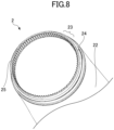
outer container 2 is a bottomed tube-shaped self-standing container with an opening O4 formed at the upper end, wherein the outer container is configured to accommodate theinner container 1 in a replaceable manner, and serves as an outer container that is on the outer side in thedouble container 100. Theouter container 2 has a bottom 21 and a side wall (outer wall) 22. Theside wall 22 includes an upper-endthin side wall 23 at the upper end thereof. The upper-endthin side wall 23 hasscrew threads 24 on the outer surface thereof, and has ajagged surface 25, in which a plurality of indentations extending in the longitudinal direction are formed, on the inner surface thereof. The innerjagged surface 25 is a rotation restricting part of theouter container 2. - The
outer container 2 of the present invention is made of, for example, resin, glass, wood, silicon, metal, paper, and the like. In a case of resin, theouter container 2 is made of, for example, resin such as PP, PE, ABS, PBS, POM, PET, or polyester-based resins, biodegradable resins, and the like, similarly to theinner container 1 described above. Examples of wood include: wood of needle-leaf trees such as cedar, cypress, pine, and the like; wood of broad-leaf trees such as oak, walnut, black cherry, alder, rubberwood, and the like; and bamboo. An example of paper is self-standing cardboard. - The first connecting
member 4 of the connectingpart 3 is a two-stage tube-shaped member and has an opening O3 that is larger than the outer diameter of themouth part 14 and through which the mouth part of the inner container can be inserted. As illustrated inFIG. 3 , the first connectingmember 4 is a cover member configured to be threadedly engaged with the outer surface of theside wall 22 of theouter container 2 while covering theshoulder part 13 of theinner container 1. - The second connecting
member 5 of the connectingpart 3 is an approximately tube-shaped rotation restricting member that has an opening O2, through which an upper part of themouth part 14 of theinner container 1 is inserted, and that is situated on the inner side of the first connectingmember 4. The second connectingmember 5 can be engaged with the first connectingmember 4 while being restricted from rotation relative to it. The second connectingmember 5 can also be engaged with a part of themouth part 14 of theinner container 1 while being restricted from rotation relative to it. - The first connecting
member 4 and the second connectingmember 5 are made of resin such as, for example, PP, PE, ABS, PBS, POM, PET, or polyester-based resins, biodegradable resins, and the like. - The
inner plug 6 is a discharge amount adjusting part that is attached in the center hole O1 of themouth part 14 of theinner container 1, and in which a discharge port for discharging the content in an adequate amount is formed. Theinner plug 6 is made of, for example, elastic rubber or resin (for example, PP, PE) . - The
cap 7 is a capping part of theinner container 1, and is configured to cover the upper part and the circumference of themouth part 14 of theinner container 1. Thecap 7 is made of, for example, resin such as PP, PE, ABS, PBS, POM, PET, or polyester-based resins, a biodegradable resin, and the like. -
FIG. 5 is an oblique exploded bottom view of the connectingpart 3.FIG. 6 is a cross-sectional view of the connectingpart 3. The configuration of the connecting part will be described with reference toFIGS. 4 to 6 . - The first connecting
member 4 has anouter tube 41, an outerannular plate 43, anupright tube 44, and an upper-end ring 45. The first connectingmember 4 has a two-stage tube shape including: theouter tube 41 having a larger diameter; and theupright tube 44 having a smaller diameter. - The
outer tube 41 is an outer tubular part that can be threadedly engaged with theouter container 2, andscrew threads 42 are provided on the inner circumferential surface of theouter tube 41. Thescrew threads 42 of theouter tube 41 are threadedly engaged with thescrew threads 24 of theouter container 2. Further, anannular projection 46 is provided on the inner circumferential surface of theouter tube 41 above thescrew threads 42. A portion sandwiched between theannular projection 46 and the lower surface of the outerannular plate 43 at the upper end of the inner circumferential surface of theouter tube 41 is a fitting groove 47 (seeFIG. 6 ). - The outer
annular plate 43 is an annular plate extending inward from the upper end of theouter tube 41 so as to reduce the diameter of the outer tube. Theupright tube 44 stands upright on the inner rim of the outerannular plate 43. The upper-end ring 45 is a small-diameter upper-end annular plate extending inward from the upper end of theupright tube 44 so as to reduce the diameter of the upright tube. - The second connecting
member 5 includes a fit-intube 51, anannular support plate 53, anupright tube 54, an upper-end diameter-reducingring 56, and a plurality of locking hooks 58.Outer ribs 52 are formed on the outer circumferential surface of the fit-intube 51. A plurality ofinner ribs 57 are provided on the inner circumferential surface of theupright tube 54 under the upper-end diameter-reducingring 56. - In the second connecting
member 5, theupright tube 54 stands upright on the inner rim of theannular support plate 53, which is an annular plate, and the fit-intube 51 is suspended from the lower surface of theannular support plate 53 at a position that is slightly on the inner side of the outer rim of the annular support plate. The outer rim of theannular support plate 53 is located on the outer side of the upper end of the fit-intube 51. - Regions of the
upright tube 54 that face the locking hooks 58 are arc-shaped diameter-increasingregions 55 located at positions that are more outward than the remaining regions of the upright tube. The upper-end diameter-reducingring 56 is a small-diameter upper-end annular plate extending inward from the upper end of theupright tube 54 and from the upper ends of the diameter-increasingregions 55 so as to reduce their diameters. - The plurality of linear
outer ribs 52 provided on the outer surface of the lower fit-intube 51 of the second connectingmember 5 are an outer-circumference rotation restricting part configured to restrict rotation relative to theouter container 2. On the other hand, theinner ribs 57 provided on the inner surface of theupper upright tube 54 are an inner-circumference rotation restricting part configured to restrict rotation relative to theinner container 1, and include a plurality of plate-shaped ribs. The inner-circumference rotation restricting part and the outer-circumference rotation restricting part of the second connectingmember 5 may be structured in other forms, and, for example, different numbers of linear ribs may be provided, or the inner surface or the outer surface may have a polygonal cross-sectional shape. - As illustrated in
FIG. 6 , the locking hooks 58 are elastic engaging pieces that are suspended in a cantilever-like manner from the inner rim of the upper-end diameter-reducingring 56, which constitutes the upper end, and have an outward spring property. The locking hooks 58 each include an extendingpart 581 that extends in the vertical direction, and a lockingprojection 582 that is provided about the lower end of the inner surface of the extendingpart 581 and projects inward. - The plurality of locking hooks 58 are provided in the circumferential direction.
FIGS. 4 and5 illustrate an example in which three locking hooks 58 are provided, but the locking hooks 58 may be provided in any plural number. - During manufacture of the connecting
part 3, thrusting the second connectingmember 5 with a strong force against the first connectingmember 4 from beneath causes theannular support plate 53 of the second connectingmember 5 to climb past theannular projection 46, and then causes the outer rim of theannular support plate 53 of the second connectingmember 5 to become fitted into thefitting groove 47 that serves as an inner boundary between theouter tube 41 and the outerannular plate 43 of the first connecting member 4 (see the cross-sectional view ofFIG. 6 ). Thus, after the first connectingmember 4 and the second connectingmember 5 are engaged with each other, the second connectingmember 5 is fixed unmovable in the vertical direction relative to the first connectingmember 4. - In the state of the connecting
part 3 illustrated inFIG. 6 , the lower surface of the upper-end ring 45 of the first connectingmember 4 and the upper surface of the upper-end diameter-reducingring 57 of the second connectingmember 5 are in contact with each other, and the inner surface of theupright tube 44 and the outer surfaces of the diameter-increasingregions 55 are in contact with each other. - In this state of the connecting
part 3, many parts of the first connectingmember 4 and the second connectingmember 5, i.e., (thefitting groove 47 and the outer rim of the annular support plate 53), (the lower surface of the upper-end ring 45 and the upper surface of the upper-end diameter-reducing ring 57), and (the inner surface of theupright tube 44 and the outer surfaces of the diameter-increasing regions 55) are in snug contact with each other. Therefore, in the connectingpart 3 before the double container assembly, the second connectingmember 5 can rotate relative to the first connectingmember 4 while being under a moderate resistance owing to friction over the wide contact area. -
FIG. 7 is an oblique view of themouth part 14 of theinner container 1 and its surroundings. The outer circumferential surface of thetubular mouth part 14 of theinner container 1 is provided with alower flange 15, anupper flange 16, a plurality of plate-shapedribs FIG. 4 ) . - The
lower flange 15 and theupper flange 16 are annular members extending outward from the outer circumferential surface of themouth part 14. The outer diameter of the outer rim of thelower flange 15 is larger than that of theupper flange 16. - The plurality of plate-shaped
ribs lower flange 15 and theupper flange 16, and provided so as to extend outward from the outer circumferential surface of themouth part 14. Of the plate-shaped ribs, the lower one is thelower rib 17 projecting long, and the upper one is theupper rib 18 projecting short. Theupper rib 18 extends outward by the same length as theupper flange 16, and thelower rib 17 extends outward slightly shorter than thelower flange 15 and longer than theupper rib 18, such that theupper rib 18 and thelower rib 17 are bounded as a step. The upper end of thelower rib 17, which constitutes the step, is arib top 17U. - Of the
mouth part 14, thelower flange 15 and the rib top 17U of thelower rib 17 function as a position restricting part. - The
lower rib 17 is a mouth part rotation restricting part of theinner container 1, and is configured to contact theinner ribs 57 of the second connectingmember 5 to restrict rotation of theinner container 1 and the second connectingmember 5 relative to each other. - The
upper flange 16 is an intrusion inhibiting member configured to inhibit the content from intruding into the connectingpart 3, and theupper rib 18 is a member configured to adjust the connectingpart 3 so as not to be inclined in the thickness direction during assembly. - Here, the inner container (refill container) 1 and the
cap 7, which are illustrated inFIG. 7 , and theinner plug 6 provided on an as-needed basis, form a refill α replaceable together with its content, as opposed to theouter container 2, the first connectingmember 4, and the second connectingmember 5 of thedouble container 100. -
FIG. 8 is an enlarged oblique view of the upper part of theouter container 2. As illustrated inFIGS. 4 and8 , theouter container 2 has the bottom 21 and theside wall 22. - The upper end of the
side wall 22 is the upper-endthin side wall 23 reduced on the outer side, and the upper-endthin side wall 23 is provided with thescrew threads 24 on the outer surface, and with thejagged surface 25 on the inner circumferential surface, recesses and projections extending in the longitudinal direction being repeatedly provided in the jagged surface. Thejagged surface 25 is a rotation restricting part of theouter container 2. The rotation restricting part provided on the inner surface of theouter container 2 may be structured in any other form, and, for example, liner ribs or liner slits may be provided in a less number, or the top-view shape may be a polygonal shape. -
FIG. 9 is an enlarged cross-sectional view of the mouth part of thedouble container 100 of the present invention and its surroundings.FIG. 9 is an enlarged view of the region X denoted by the dashed line inFIG. 3 .FIG. 10 is a cross-sectional view illustrating engagement between theinner container 1 and the connectingpart 3, and is a cross-sectional view along the surface A illustrated inFIGS. 3 and9 .FIG. 11 is a cross-sectional view illustrating engagement between theouter container 2 and the connectingpart 3, and is a cross-sectional view along the surface B illustrated inFIGS. 3 and9 . - As illustrated in
FIG. 9 , in the assembled state, the engagement is established such that the upper surface of the upper-end ring 45 of the first connectingmember 4 is positioned substantially on the same plane as the upper surface of theupper flange 16 of themouth part 14 of theinner container 1. Specifically, the upper-end ring 45 of the first connectingmember 4 and the upper-end diameter-reducingring 56 of the second connectingmember 5 are positioned so as to overlap therib top 17U, which is the step of themouth part 14. Here, the inner rim of the upper-end ring 45 faces the outer rim of theupper flange 16, and the inner rim of the upper-end diameter-reducingring 56 faces the outer end of theupper rib 18. - Therefore, in the assembled state in which the
inner container 1 and theouter container 2 are connected via the connectingpart 3, the user can use the assembleddouble container 100 without any discomfort because there are few recesses or projections exposed to the outside. - Here, as illustrated in the cross-sectional view of
FIG. 10 , in the assembled state, thelower ribs 17 of theinner container 1 are engaged while being fitted in between the plurality of plate-shapedinner ribs 57 of the second connectingmember 5. As a result, the second connectingmember 5 is engaged with theinner container 1 such that it cannot rotate relative to the inner container. - In addition, as illustrated in the cross-sectional view of
FIG. 11 , in the assembled state, theouter ribs 52 of the fit-intube 51 of the second connectingmember 5 are engaged while being fitted in the recesses in thejagged surface 25 on the inner side of the upper-endthin side wall 23 of theouter container 2. As a result, the second connectingmember 5 is engaged with theouter container 2 while being restricted from rotation relative to it. - In the assembled state, by the second connecting
member 5 being engaged as illustrated inFIGS. 10 and11 , theinner container 1 is restricted from rotation relative to theouter container 2. - As illustrated in
FIG. 9 ,screw threads 72 are formed on the inner surface of acircumferential wall 71 of thecap 7, and thecap 7 is attachable to theinner container 1 by being threadedly engaged with thescrew threads 19 formed on the outer circumferential surface of theinner container 1 above themouth part 14. - Only the first connecting
member 4 of the connectingpart 3 of the present invention can suffice in connecting theouter container 2 and theinner container 1. However, with provision of the second connectingmember 5, theinner container 1 is restricted from rotation relative to theouter container 2 because the second connectingmember 5 is restricted from rotation relative to both of theouter container 2 and theinner container 1 as illustrated inFIGS. 10 and11 . - Thus, when the
cap 7 is rotated relative to themouth part 14, theinner container 1 does not rotate relative to theouter container 2. That is, with thedouble container 100, conjunctive rotation of thecap 7 and theinner container 1 can be inhibited when thecap 7 is opened or closed. - Next, replacement of refills will be described with reference to
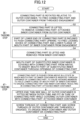
FIGS. 12 to 15 . -
FIG. 12 is a flowchart of the replacement of refills in the double container of the present invention.FIG. 13 is a view illustrating removal of a connecting part-attached inner container β from theouter container 2.FIG. 14 is a cross-sectional view illustrating removal of the connectingpart 3 of the present invention from theinner container 1.FIG. 15 is a cross-sectional view illustrating attaching of the connectingpart 3 of the present invention to theinner container 1. - The first connecting
member 4 and the second connectingmember 5 are previously engaged as a state before being put on sale, and the connectingpart 3 is in a disassemblable state. - When replacing the current inner container with a new refill since the content has decreased, the connecting
part 3 is first rotated relative to theouter container 2 in the step S1 to free the connectingpart 3 and theouter container 2 from threaded engagement (i.e., to free thescrew threads 42 of the first connectingmember 4 and thescrew threads 24 of theouter container 2 from engagement). - In the step S2, the connecting
part 3 is lifted to remove the connecting part-attached inner container β from theouter container 2. The state in the step S2 is illustrated inFIG. 13 . - In the step S3, the connecting
part 3 is pushed upward with a force applied to a part thereof, to free the locking hooks 58 of the connectingpart 3 from engagement with the position restricting part (lower flange 15) of the inner container, one by one. The state in the step S3 is illustrated inFIG. 14 . Since the locking hooks 58 are elastically deformable outward, as illustrated inFIG. 14 , disengagement of one of the locking hooks 58 from thelower flange 15 by application of the force to the part of the connectingpart 3 causes the other locking hooks 58 to be disengaged one after another. - In the step S4, the connecting
part 3 is lifted and removed from theinner container 1 having no remaining content or a low remaining content. - In the step S5, while covering an inner container 1 (cap-attached inner container), which is a substituted refill, with the connecting
part 3 from above the inner container, themouth part 14 of the substitutedinner container 1 is inserted through the openings O2 and O3 of the connectingpart 3. - In the step S5, in the state in which the
mouth part 14 of the substitutedinner container 1 is inserted into the openings O2 and O3 of the connectingpart 3, the locking hooks 58 and thelower flange 15 of theinner container 1 are engaged, to thereby engage the connectingpart 3 and theinner container 1. - In the step S6, in the state in which the
mouth part 14 of theinner container 1 is inserted into the openings O2 and O3 of the connectingpart 3, the connectingpart 3 is pushed downward to engage the locking hooks 58 and thelower flange 15 of theinner container 1. As a result, the connectingpart 3 and theinner container 1 are engaged. - In the step S7, while covering the
outer container 2 with the connectingpart 3 of the connecting part-attached refill container, the upper-endthin side wall 23 of theouter container 2 is fitted between the outer-sideouter tube 41 and the inner-side fit-intube 51 of the connectingpart 3. - In the step S8, the
screw threads 42 of the first connectingmember 4 and thescrew threads 24 of theouter container 2 are threadedly engaged to complete the engagement between theinner container 1 and theouter container 2 via the connectingpart 3. - By the
screw threads 24 of theouter container 2 and thescrew threads 42 of the first connectingmember 4 being threadedly engaged in the step S8, the distance between theouter tube 41 and the inner-side fit-intube 51 becomes short in the connectingpart 3, and thejagged surface 25 of theouter container 2 and theouter ribs 52 of the second connectingmember 5 are engaged. In the state in which the connectingpart 3 is threadedly engaged with theouter container 2 by this engagement, the connectingpart 3 is restricted from rotation relative to theouter container 2. - When removing the connecting
part 3 from theinner container 1 in the step S2, a force is applied upward to a part of the connectingpart 3 as illustrated inFIG. 14 . Here, a lockinghook 58 on the side where no force is applied deforms to be kept engaged with thelower flange 15, while onelocking hook 58 on the side where the force is applied is disengaged from thelower flange 15, thereby freeing the locking hooks 58 from the engaged state in order. In this way, the connectingpart 3 is removed. - On the other hand, when engaging the connecting
part 3 with theinner container 1 in the step S6, as illustrated inFIG. 15 , a force is applied uniformly to the connectingpart 3 from above. Here, the plurality of locking hooks 58 gets pushed while spreading uniformly by having contact with the outer rim of theupper flange 16 and the plate-shapedribs projections 582 reach the bottom of thelower flange 15, as illustrated inFIG. 9 , while the portions of the lower surface of the upper-end diameter-reducingring 56 where the locking hooks 58 are not provided and the rib tops 17U are having contact with each other, the lockingprojections 582 become hooked on the lower end of the outer rim of thelower flange 15. By the locking hooks 58 holding thelower flange 15, the connectingpart 3 becomes engaged with theinner container 1. - By changing how to apply the force, it is possible to easily attach or detach the locking hooks 58 of the second connecting
member 5 to or from thelower flange 15, which is the position restricting part of theinner container 1, making it possible to repeatedly attach or detach the connectingpart 3 to or from theinner container 1. - Therefore, in the double container according to the present invention, the inner container can serve as a refill that can be replaced, together with its content, with respect not only to the outer container but also to the connecting part made of the first connecting member and the second connecting member.
- Therefore, the connecting part can also be removed from the inner container and reused repeatedly together with the outer container. Therefore, there are more parts that can be reused, and it is possible to reduce resin loss. Therefore, the double container according to the present invention can inhibit conjunctive rotation of the cap and the inner container while minimizing the amount of resins used in the refill inner container.
- Although the preferred embodiment of the present invention has been described in detail above, the present invention is not limited to the specific embodiment, and various changes and modifications are applicable within the scope of the spirit of the embodiment of the present invention described in the claims.
- The present international application claims priority to
Japanese Patent Application No. 2022-022377 filed February 16, 2022 -
- 1 inner container (refill container)
- 2 outer container
- 3 connecting part
- 4 first connecting member
- 5 second connecting member
- 6 inner plug
- 7 cap
- 10 bottle body
- 11 bottom
- 12 trunk
- 13 shoulder part
- 14 mouth part
- 15 lower flange (position restricting part)
- 16 upper flange (intrusion inhibiting member)
- 17 lower rib (mouth part rotation restricting part)
- 17U rib top (position restricting part)
- 18 upper rib
- 19 screw thread
- 21 bottom
- 22 side wall
- 23 upper-end thin side wall
- 24 screw thread
- 25 jagged surface (rotation restricting part)
- 41 outer tube
- 42 screw thread
- 43 outer annular plate
- 44 upright tube
- 45 upper-end ring
- 46 annular projection
- 47 fitting groove
- 51 fit-in tube
- 52 outer rib (outer-circumference rotation restricting part)
- 53 annular support plate
- 54 upright tube
- 55 diameter-increasing region
- 56 upper-end diameter-reducing ring
- 57 inner rib (inner-circumference rotation restricting part)
- 58 a plurality of locking hooks
- α refill
- β connecting part-attached inner container
Claims (11)
- A double container, comprising:an inner container including a mouth part and a shoulder part;an outer container having a side wall, the outer container being configured to accommodate the inner container in a replaceable manner;a first connecting member having a two-stage tube shape, the first connecting member having an opening through which the mouth part of the inner container can be inserted, and the first connecting member being configured to be threadedly engaged with an outer surface of the side wall of the outer container while covering the shoulder part of the inner container and an upper end of the side wall; anda second connecting member having an approximately tube shape, the second connecting member having an opening through which the mouth part of the inner container can be inserted, and the second connecting member being situated on an inner side of the first connecting member,wherein the second connecting member comprises:an inner-circumference rotation restricting part configured to contact a part of the mouth part of the inner container to restrict rotation relative to the mouth part; andan outer-circumference rotation restricting part configured to contact a part of the side wall of the outer container to restrict rotation relative to the outer container, andin an assembled state, the inner container is restricted from rotation relative to the outer container.
- The double container according to claim 1,wherein the second connecting member includes a fit-in tube, the outer-circumference rotation restricting part being formed on an outer surface of the fit-in tube,the outer container includes a rotation restricting part that is provided on an inner surface of the side wall,when the inner container and the outer container are connected, the side wall of the outer container is fitted between: a part of the first connecting member, the first connecting member being on an outer side; and the fit-in tube of the second connecting member that is situated on the inner side,after the outer container and the first connecting member are threadedly engaged, the rotation restricting part on the inner surface of the side wall of the outer container and the outer-circumference rotation restricting part of the fit-in tube of the second connecting member are engaged, thereby restricting the second connecting member from rotation relative to the outer container.
- The double container according to claim 2,wherein the outer-circumference rotation restricting part of the fit-in tube of the second connecting member is a linear rib, andthe rotation restricting part on the side wall of the outer container is a jagged inner surface in which a recess and a projection extending in a longitudinal direction are repeatedly provided.
- The double container according to claim 1,wherein a cap having a screw thread on an inner circumferential surface thereof is attachable to the double container by the cap being threadedly engaged with a screw thread formed on an outer circumferential surface of the inner container above the mouth part, andwhen the cap is rotated relative to the mouth part, the inner container is restricted from rotation relative to the outer container.
- The double container according to claim 1,wherein the second connecting member is repeatedly attachable to and detachable from the inner container, andthe inner container, together with its content, serves as a replaceable refill with respect to the outer container, to the first connecting member, and to the second connecting member.
- The double container according to claim 5,wherein the mouth part of the inner container includes a position restricting part that is located on an outer side of an outer circumferential surface of the mouth part,the second connecting member includes a plurality of locking hooks that are suspended in a cantilever-like manner from an inner rim of an upper end of the two-stage tube shape, the locking hooks having an outward spring property,a locking projection projecting inward is formed on a lower end of an inner side of each of the locking hooks, andthe plurality of locking hooks are elastically deformed such that the locking projection holds and engages with the position restricting part of the mouth part, thereby causing the second connecting member to be engaged with the mouth part of the inner container while being restricted relative to the mouth part in a vertical direction.
- The double container according to claim 6,wherein the position restricting part of the mouth part of the inner container includes:a lower flange extending outward from the outer circumferential surface of the mouth part; andan upper end surface of a mouth part rotation restricting part that is provided upright so as to be continuously joined with an upper surface of the lower flange,the second connecting member includes an upright tube, the inner-circumference rotation restricting part being provided on an inner circumferential surface of the upright tube, andwhen the inner-circumference rotation restricting part of the second connecting member and the mouth part rotation restricting part are engaged with each other, the second connecting member is restricted from rotation relative to the inner container.
- The double container according to claim 7,
wherein the inner-circumference rotation restricting part of the second connecting member includes a plurality of plate-shaped ribs projecting inward from the inner circumferential surface of the upright tube and extending in the vertical direction. - The double container according to claim 1,wherein the first connecting member includes:an outer tube having a screw thread on an inner circumferential surface of the outer tube, the screw thread being able to be threadedly engaged with the outer container;an outer annular plate extending inward from an upper end of the outer tube;an upright tube standing upright on an inner rim of the outer annular plate; andan upper-end ring extending inward from a top of the upright tube,the mouth part has an upper flange above a position at which the mouth part engages with the second connecting member, andin the assembled state, the upper-end ring of the first connecting member and the upper flange of the mouth part are positioned substantially on a same plane.
- A method for attaching a refill in a double container, wherein in the double container, an inner container, together with its content, serves as a refill with respect to an outer container, to a first connecting member, and to a second connecting member, the method comprising:previously engaging the first connecting member and the second connecting member, which is to be situated on an inner side of the first connecting member, with each other, to prepare them as a connecting part;engaging the second connecting member and the inner container with each other in a state in which a mouth part of the inner container is inserted through an opening of the first connecting member, to thereby engage the connecting part and the inner container with each other; andthreadedly engaging the second connecting member and the outer container with each other, to thereby engage the inner container and the outer container with each other via the connecting part.
- A connecting part for connecting an inner container including a mouth part and an outer container configured to accommodate the inner container in a replaceable manner, the connecting part comprising:a first connecting member threadedly engageable with the outer container and having an opening that is larger than an outer diameter of the mouth part of the inner container; anda second connecting member having an approximately tube shape and having an opening through which the mouth part of the inner container can be inserted, the second connecting member being situated on an inner side of the first connecting member,wherein the second connecting member comprises:an inner-circumference rotation restricting part configured to contact a part of the mouth part of the inner container to restrict rotation relative to the mouth part; andan outer-circumference rotation restricting part configured to contact a part of a side wall of the outer container to restrict rotation relative to the outer container, andby the inner container and the outer container being assembled on each other via the connecting part, the inner container is restricted from rotation relative to the outer container.
Applications Claiming Priority (2)
| Application Number | Priority Date | Filing Date | Title |
|---|---|---|---|
| JP2022022377 | 2022-02-16 | ||
| PCT/JP2023/004234 WO2023157736A1 (en) | 2022-02-16 | 2023-02-08 | Double container, method for attaching refill in double container, and connecting parts |
Publications (2)
| Publication Number | Publication Date |
|---|---|
| EP4480847A1 true EP4480847A1 (en) | 2024-12-25 |
| EP4480847A4 EP4480847A4 (en) | 2025-06-18 |
Family
ID=87578113
Family Applications (1)
| Application Number | Title | Priority Date | Filing Date |
|---|---|---|---|
| EP23756262.4A Withdrawn EP4480847A4 (en) | 2022-02-16 | 2023-02-08 | Double container, method for attaching refill in double container, and connecting parts |
Country Status (4)
| Country | Link |
|---|---|
| US (1) | US12649616B2 (en) |
| EP (1) | EP4480847A4 (en) |
| CN (1) | CN118574777A (en) |
| WO (1) | WO2023157736A1 (en) |
Family Cites Families (23)
| Publication number | Priority date | Publication date | Assignee | Title |
|---|---|---|---|---|
| US4915255A (en) * | 1988-09-22 | 1990-04-10 | Cytosciences, Inc. | Transportable specimen container including removable centrifuge tube |
| FR2688488B1 (en) * | 1992-03-16 | 1994-05-06 | Cebal Sa | TUBE AND DISPENSER COMPRISING SAME FOR STORING AND DISPENSING TWO CREAMY OR PASTY PRODUCTS. |
| JPH0575163U (en) | 1992-03-18 | 1993-10-12 | 凸版印刷株式会社 | Easy refill container |
| US6176395B1 (en) * | 1999-04-21 | 2001-01-23 | Pechiney Plastic Packaging, Inc. | Dual dispense container |
| US6085927A (en) * | 1999-07-12 | 2000-07-11 | Owens-Illinois Closure Inc. | Container with insert to reduce effective volume and package incorporating same |
| US6997353B2 (en) * | 2003-03-26 | 2006-02-14 | Airlesssystems | Fluid product dispenser |
| JP4396889B2 (en) * | 2004-03-31 | 2010-01-13 | 株式会社吉野工業所 | Double container |
| JP4396888B2 (en) * | 2004-03-31 | 2010-01-13 | 株式会社吉野工業所 | Double container |
| US7435027B2 (en) * | 2005-03-04 | 2008-10-14 | Cosmolab Inc. | Multi-reservoir container with applicator tip and method of making the same |
| CH698173B1 (en) * | 2005-11-08 | 2009-06-15 | Belcap Switzerland Ag | Container closure to simultaneously pour out two separate liquids with a specified quantitative ratio. |
| JP2008007160A (en) * | 2006-06-29 | 2008-01-17 | Yoshino Kogyosho Co Ltd | Double container |
| JP4818867B2 (en) | 2006-09-29 | 2011-11-16 | 株式会社吉野工業所 | Double container |
| JP4919877B2 (en) * | 2007-05-30 | 2012-04-18 | 株式会社吉野工業所 | Double container |
| US7594589B2 (en) * | 2007-06-14 | 2009-09-29 | Owens-Brockway Glass Container Inc. | Dual-container package and a dispensing closure for such package |
| JP5227346B2 (en) | 2009-01-30 | 2013-07-03 | 株式会社 資生堂 | Double container |
| JP6442324B2 (en) * | 2015-02-27 | 2018-12-19 | 株式会社吉野工業所 | Double container |
| JP7266083B2 (en) | 2017-12-04 | 2023-04-27 | 株式会社オービック | Data display device, data display method and data display program |
| KR101900419B1 (en) * | 2018-02-22 | 2018-09-20 | (주)연우 | Dual container |
| FR3089431B1 (en) * | 2018-12-05 | 2021-01-01 | Qualipac Sa | PACKAGING AND DISTRIBUTION DEVICE PER DOSE OF A FLUID PRODUCT, INCLUDING A REUSABLE BOTTLE |
| DE202019103061U1 (en) * | 2019-05-29 | 2020-09-01 | Louvrette Gmbh Design X Packaging | Device for storing and dispensing a liquid or pasty mass |
| KR102271373B1 (en) | 2019-12-19 | 2021-06-30 | (주)연우 | Dual container |
| KR102332817B1 (en) * | 2020-03-16 | 2021-11-30 | (주)연우 | Dual container |
| CN113928677B (en) * | 2021-11-08 | 2025-09-02 | 浙江正庄实业有限公司 | High-rigidity polymer strong buckle type large ring vacuum bottle and preparation method thereof |
-
2023
- 2023-02-08 US US18/727,489 patent/US12649616B2/en active Active
- 2023-02-08 CN CN202380017276.8A patent/CN118574777A/en active Pending
- 2023-02-08 WO PCT/JP2023/004234 patent/WO2023157736A1/en not_active Ceased
- 2023-02-08 EP EP23756262.4A patent/EP4480847A4/en not_active Withdrawn
Also Published As
| Publication number | Publication date |
|---|---|
| US20250091784A1 (en) | 2025-03-20 |
| WO2023157736A1 (en) | 2023-08-24 |
| US12649616B2 (en) | 2026-06-09 |
| JPWO2023157736A1 (en) | 2023-08-24 |
| CN118574777A (en) | 2024-08-30 |
| EP4480847A4 (en) | 2025-06-18 |
Similar Documents
| Publication | Publication Date | Title |
|---|---|---|
| CN110114283B (en) | package | |
| US8613372B2 (en) | Dispensing cap for a container | |
| US4723671A (en) | Bottle cap stand | |
| US8857636B2 (en) | Sectional container with a detachable base and lid cover | |
| US7618208B2 (en) | Attachment means for a cosmetic dispenser | |
| US20060006192A1 (en) | Independent off-bottle dispensing closure | |
| EP3603817B1 (en) | Easy mounting and removal of a pump relative to the container | |
| CN116888055A (en) | Containers and systems for reducing packaging waste | |
| US7044669B2 (en) | Packaging device for a fluid product | |
| MX2012012544A (en) | Bottle accessory for attaching a retractable spout to a bottle using a cap. | |
| CN117858650A (en) | Deformable plastic containers and systems for reducing plastic waste | |
| JP5582911B2 (en) | Container with spout | |
| JPH0626573A (en) | Cover body for vessel | |
| US20070272698A1 (en) | An Improved Container | |
| CN107108077B (en) | container for batter | |
| US20250091784A1 (en) | Double container, method for attaching refill in double container, and connecting part | |
| JP7416442B2 (en) | double container | |
| JP5590554B2 (en) | Application container | |
| JP2004323113A (en) | Assemblies for packaging and application of liquid products | |
| US20240075486A1 (en) | Refillable container-dispenser system with trigger sprayer and closure | |
| JP2010155620A (en) | Replacing container | |
| JP7797286B2 (en) | Refill container and double container containing the same | |
| JP7482814B2 (en) | Refillable double container | |
| JP3266412B2 (en) | Container | |
| JP2013193749A (en) | Squeeze pinching tool and squeeze container using the same |
Legal Events
| Date | Code | Title | Description |
|---|---|---|---|
| STAA | Information on the status of an ep patent application or granted ep patent |
Free format text: STATUS: THE INTERNATIONAL PUBLICATION HAS BEEN MADE |
|
| PUAI | Public reference made under article 153(3) epc to a published international application that has entered the european phase |
Free format text: ORIGINAL CODE: 0009012 |
|
| STAA | Information on the status of an ep patent application or granted ep patent |
Free format text: STATUS: REQUEST FOR EXAMINATION WAS MADE |
|
| 17P | Request for examination filed |
Effective date: 20240715 |
|
| AK | Designated contracting states |
Kind code of ref document: A1 Designated state(s): AL AT BE BG CH CY CZ DE DK EE ES FI FR GB GR HR HU IE IS IT LI LT LU LV MC ME MK MT NL NO PL PT RO RS SE SI SK SM TR |
|
| REG | Reference to a national code |
Ref country code: DE Ref legal event code: R079 Free format text: PREVIOUS MAIN CLASS: B65D0077040000 Ipc: B65D0083000000 |
|
| DAV | Request for validation of the european patent (deleted) | ||
| DAX | Request for extension of the european patent (deleted) | ||
| A4 | Supplementary search report drawn up and despatched |
Effective date: 20250519 |
|
| RIC1 | Information provided on ipc code assigned before grant |
Ipc: B05B 11/00 20230101ALI20250513BHEP Ipc: B65D 83/00 20060101AFI20250513BHEP |
|
| STAA | Information on the status of an ep patent application or granted ep patent |
Free format text: STATUS: THE APPLICATION IS DEEMED TO BE WITHDRAWN |
|
| 18D | Application deemed to be withdrawn |
Effective date: 20251209 |