EP4480836A1 - A method and apparatus for filling a pouch - Google Patents
A method and apparatus for filling a pouch Download PDFInfo
- Publication number
- EP4480836A1 EP4480836A1 EP23180169.7A EP23180169A EP4480836A1 EP 4480836 A1 EP4480836 A1 EP 4480836A1 EP 23180169 A EP23180169 A EP 23180169A EP 4480836 A1 EP4480836 A1 EP 4480836A1
- Authority
- EP
- European Patent Office
- Prior art keywords
- pouch
- fold
- lower portion
- forming plate
- layers
- Prior art date
- Legal status (The legal status is an assumption and is not a legal conclusion. Google has not performed a legal analysis and makes no representation as to the accuracy of the status listed.)
- Pending
Links
Images







Classifications
-
- B—PERFORMING OPERATIONS; TRANSPORTING
- B65—CONVEYING; PACKING; STORING; HANDLING THIN OR FILAMENTARY MATERIAL
- B65B—MACHINES, APPARATUS OR DEVICES FOR, OR METHODS OF, PACKAGING ARTICLES OR MATERIALS; UNPACKING
- B65B3/00—Packaging plastic material, semiliquids, liquids or mixed solids and liquids, in individual containers or receptacles, e.g. bags, sacks, boxes, cartons, cans, or jars
- B65B3/02—Machines characterised by the incorporation of means for making the containers or receptacles
-
- B—PERFORMING OPERATIONS; TRANSPORTING
- B65—CONVEYING; PACKING; STORING; HANDLING THIN OR FILAMENTARY MATERIAL
- B65B—MACHINES, APPARATUS OR DEVICES FOR, OR METHODS OF, PACKAGING ARTICLES OR MATERIALS; UNPACKING
- B65B43/00—Forming, feeding, opening or setting-up containers or receptacles in association with packaging
- B65B43/26—Opening or distending bags; Opening, erecting, or setting-up boxes, cartons, or carton blanks
- B65B43/30—Opening or distending bags; Opening, erecting, or setting-up boxes, cartons, or carton blanks by grippers engaging opposed walls, e.g. suction-operated
-
- B—PERFORMING OPERATIONS; TRANSPORTING
- B65—CONVEYING; PACKING; STORING; HANDLING THIN OR FILAMENTARY MATERIAL
- B65B—MACHINES, APPARATUS OR DEVICES FOR, OR METHODS OF, PACKAGING ARTICLES OR MATERIALS; UNPACKING
- B65B43/00—Forming, feeding, opening or setting-up containers or receptacles in association with packaging
- B65B43/42—Feeding or positioning bags, boxes, or cartons in the distended, opened, or set-up state; Feeding preformed rigid containers, e.g. tins, capsules, glass tubes, glasses, to the packaging position; Locating containers or receptacles at the filling position; Supporting containers or receptacles during the filling operation
- B65B43/54—Means for supporting containers or receptacles during the filling operation
-
- B—PERFORMING OPERATIONS; TRANSPORTING
- B65—CONVEYING; PACKING; STORING; HANDLING THIN OR FILAMENTARY MATERIAL
- B65B—MACHINES, APPARATUS OR DEVICES FOR, OR METHODS OF, PACKAGING ARTICLES OR MATERIALS; UNPACKING
- B65B61/00—Auxiliary devices, not otherwise provided for, for operating on sheets, blanks, webs, binding material, containers or packages
- B65B61/24—Auxiliary devices, not otherwise provided for, for operating on sheets, blanks, webs, binding material, containers or packages for shaping or reshaping completed packages
-
- B—PERFORMING OPERATIONS; TRANSPORTING
- B31—MAKING ARTICLES OF PAPER, CARDBOARD OR MATERIAL WORKED IN A MANNER ANALOGOUS TO PAPER; WORKING PAPER, CARDBOARD OR MATERIAL WORKED IN A MANNER ANALOGOUS TO PAPER
- B31B—MAKING CONTAINERS OF PAPER, CARDBOARD OR MATERIAL WORKED IN A MANNER ANALOGOUS TO PAPER
- B31B70/00—Making flexible containers, e.g. envelopes or bags
-
- B—PERFORMING OPERATIONS; TRANSPORTING
- B31—MAKING ARTICLES OF PAPER, CARDBOARD OR MATERIAL WORKED IN A MANNER ANALOGOUS TO PAPER; WORKING PAPER, CARDBOARD OR MATERIAL WORKED IN A MANNER ANALOGOUS TO PAPER
- B31B—MAKING CONTAINERS OF PAPER, CARDBOARD OR MATERIAL WORKED IN A MANNER ANALOGOUS TO PAPER
- B31B70/00—Making flexible containers, e.g. envelopes or bags
- B31B70/001—Shaping, other than by folding, sheet material under pressure
-
- B—PERFORMING OPERATIONS; TRANSPORTING
- B31—MAKING ARTICLES OF PAPER, CARDBOARD OR MATERIAL WORKED IN A MANNER ANALOGOUS TO PAPER; WORKING PAPER, CARDBOARD OR MATERIAL WORKED IN A MANNER ANALOGOUS TO PAPER
- B31B—MAKING CONTAINERS OF PAPER, CARDBOARD OR MATERIAL WORKED IN A MANNER ANALOGOUS TO PAPER
- B31B70/00—Making flexible containers, e.g. envelopes or bags
- B31B70/003—Opening or distending bags
-
- B—PERFORMING OPERATIONS; TRANSPORTING
- B31—MAKING ARTICLES OF PAPER, CARDBOARD OR MATERIAL WORKED IN A MANNER ANALOGOUS TO PAPER; WORKING PAPER, CARDBOARD OR MATERIAL WORKED IN A MANNER ANALOGOUS TO PAPER
- B31B—MAKING CONTAINERS OF PAPER, CARDBOARD OR MATERIAL WORKED IN A MANNER ANALOGOUS TO PAPER
- B31B70/00—Making flexible containers, e.g. envelopes or bags
- B31B70/008—Stiffening or reinforcing
-
- B—PERFORMING OPERATIONS; TRANSPORTING
- B31—MAKING ARTICLES OF PAPER, CARDBOARD OR MATERIAL WORKED IN A MANNER ANALOGOUS TO PAPER; WORKING PAPER, CARDBOARD OR MATERIAL WORKED IN A MANNER ANALOGOUS TO PAPER
- B31B—MAKING CONTAINERS OF PAPER, CARDBOARD OR MATERIAL WORKED IN A MANNER ANALOGOUS TO PAPER
- B31B70/00—Making flexible containers, e.g. envelopes or bags
- B31B70/25—Surface scoring
-
- B—PERFORMING OPERATIONS; TRANSPORTING
- B65—CONVEYING; PACKING; STORING; HANDLING THIN OR FILAMENTARY MATERIAL
- B65B—MACHINES, APPARATUS OR DEVICES FOR, OR METHODS OF, PACKAGING ARTICLES OR MATERIALS; UNPACKING
- B65B51/00—Devices for, or methods of, sealing or securing package folds or closures; Devices for gathering or twisting wrappers, or necks of bags
- B65B51/10—Applying or generating heat or pressure or combinations thereof
- B65B51/14—Applying or generating heat or pressure or combinations thereof by reciprocating or oscillating members
- B65B51/146—Closing bags
Definitions
- a flat pouch i.e., a three-side seal pouch
- the pouch can be filled through the fourth side which is subsequently sealed to enclose the contents.
- Such pouches are often formed from packaging materials which have a laminated structure formed by multiple layers of different material which have desirable properties.
- the packaging material may comprise an outer layer of Polyethylene Terephthalate (PET) which can be easily printed on, an aluminium foil (or metallised (e.g., MET-PET) film) layer which provides gas, aroma and water vapour barrier properties and a Polyethylene (PE) inner layer to provide a reliable seal.
- PET Polyethylene Terephthalate
- aluminium foil or metallised (e.g., MET-PET) film
- PE Polyethylene
- Such packaging materials are able to retain their form which can be beneficial during filling.
- Such packaging materials are typically more difficult to recycle. It is therefore desirable to use mono-materials to improve sustainability. However, these materials have poor dead-fold properties which can make filling more problematic.
- a method of filling a flat pouch comprising: folding a lower portion of the pouch relative to an upper portion about a fold line; forming a shaped fold by lifting a central region of the folded lower portion such that distal regions of the lower portion on either lateral side of the central region slope downwards away from the central region, wherein the shaped fold is configured to maintain the pouch in an open configuration in which first and second layers of the pouch are separated over a top edge to form an opening into a cavity of the pouch; and filling the cavity of the pouch with product via the opening.
- the method may further comprise forming a crease between the lower portion and the upper portion which forms the fold line.
- the lower portion may be folded such that it extends perpendicularly to the upper portion.
- the central region may be lifted by a fold forming plate which rotates and/or translates between a first stowed position and a second deployed position.
- the fold forming plate may also fold the lower portion about the fold line.
- the fold forming plate may rotate about an axis.
- the axis may be positioned above the level of the fold line.
- the first and second layers of the pouch may be separated over the top edge prior to forming the shaped fold.
- the first and second layers of the pouch may be separate by a pair of vacuum cups which engage the first and second layers respectively and move away from one another in order to open the pouch.
- the method may further comprise, prior to folding the lower portion, inserting a guide into the cavity of the pouch so as to prevent the upper portion from being deflected when the lower portion is folded relative to the upper portion.
- the guide may be configured to receive the fold forming plate when in the second deployed position.
- the guide may comprise a pair of fingers which are spaced laterally from one another such that the fold forming plate can be received therebetween.
- the fold line may be adjacent to a bottom of the cavity.
- Each of the first and second layers may be formed from a mono material.
- a pouch filling apparatus configured to perform the method of described above.
- Figure 1 shows a packaging pouch 2 which may be used with the method and apparatus of the present disclosure.
- the pouch 2 is a flat pouch and comprises a first layer 4 of flexible packaging material and a second layer 6 of flexible packaging material.
- the first and second layers 4, 6 may be formed from the same material or from different materials.
- the first and second layers 4, 6 may be formed from a laminated composite material or from a mono-material.
- the first and second layers 4, 6 are sealed along a bottom edge 8 and along opposing side edges 10a, 10b to form a cavity 12 which is left open along a top edge 14 to allow filling.
- the cavity 12 has a width W 1 measured between the opposing side edges 10a, 10b and a depth D 1 measured from the top edge 14 to the bottom edge 8.
- the pouch 2 may be filled using a method and apparatus according to the present disclosure, as will be described below.
- the apparatus comprises a creasing assembly.
- the creasing assembly comprises a female creasing platen 16 and a male creasing rule 20.
- the female creasing platen 16 comprises a groove 20 which is sized to receive a corresponding rib 19 provided on the male creasing rule 18.
- the pouch 2 is located between the female creasing platen 16 and the male creasing rule 18. The pouch 2 is arranged such that the groove 20 runs parallel to the bottom edge 8 and at or adjacent to the bottom of the cavity 12.
- the male creasing rule 18 is brought towards the female creasing platen 16 and the rib 19 is received in the groove 20, thereby forming a crease 22 extending across the pouch 2, as seen in Figure 3 .
- the crease 22 forms a fold line, as will be described further below.
- the apparatus further comprises a pair of grippers 24a, 24b.
- the grippers 24a, 24b each comprise a pair of gripping jaws which are actuatable to selectively grip the pouch 2 against the first and second layers 4, 6. As shown, the grippers 24a, 24b grip the pouch 2 along the side edges 10a, 10b and adjacent the top edge 14.
- the apparatus further comprises a pair of vacuum cups 26a, 26b which are provided on arms 27a, 27b.
- the vacuum cups 26a, 26b are brought into contact with the first and second layers 4, 6 respectively adjacent to the top edge 14.
- the vacuum cups 26a, 26b engage the first and second layers 4, 6 via suction and move away from one another in order to open the pouch 2 by separating the first and second layers 4, 6 over the top edge 14. Further, to allow the first and second layers 4, 6 to be separated, the grippers 24a, 24b move towards one another, as shown.
- the movement of the grippers 24a, 24b may be actively controlled (e.g., using a suitable actuator) or passively controlled in response to the separation of the first and second layers 4, 6 creating a force which draws the grippers 24a, 24b towards one another.
- the apparatus may further comprise an air nozzle 28.
- the air nozzle 28 blows a jet of air into the cavity 12 in order to further space the first and second layers 4, 6 along the length of the cavity 12.
- the apparatus further comprises a guide 30.
- the guide 30 comprises a pair of fingers 32a, 32b which are laterally spaced from one another.
- the fingers 32a, 32b define an inner width W 2 between opposing inwardly facing surfaces and an outer width W 3 between respective outwardly facing surfaces.
- the outer width W 3 corresponds to (i.e., is slightly smaller than) the width W 1 of the cavity 12. Accordingly, the fingers 32a, 32b are received within the cavity 12 and extend parallel to the side edges 10a, 10b.
- the guide 30 is inserted such that the fingers 32a, 32b extend into or towards bottom corners of the cavity 12 (which may be rounded in some examples), as shown in Figure 7 . It will be appreciated that in other examples, the fingers 32a, 32b may be formed separately and not as part of a common guide 30.
- a fold forming plate 34 is brought under the bottom edge 8 of the pouch 2, as shown in Figure 7 .
- the fold forming plate 34 is pivotably mounted about an axis 36.
- the axis 36 is located at or towards an edge of the fold forming plate 34 and is parallel but offset from a plane of the pouch 2.
- the fold forming plate 34 is rectangular and has a width W 4 which is smaller than the inner width W 2 between the fingers 32a, 32b.
- the fold forming plate 34 has a first, stowed position in which the fold forming plate 34 is angled downwards, as shown in Figures 7 and 8 .
- the fold forming plate 34 may be angled downwards at 30 degrees from a horizontal direction (i.e., 120 degrees from a vertical direction; at the 4 o'clock position, as viewed in Figure 8 ).
- the fold forming plate 34 has a second, deployed position in which the fold forming plate 34 is angled horizontally, as shown in Figures 9 and 10 .
- the fold forming plate 34 may be angled upwards in the second position.
- the fold forming plate 34 may be angled upwards at 30 degrees from the horizontal direction (i.e., 60 degrees from the vertical direction; at the 2 o'clock position).
- the fold forming plate 34 In the first position, the fold forming plate 34 is spaced from bottom edge 8 of the pouch 2. The fold forming plate 34 is rotated about the axis 36 towards the second position by a suitable actuator. During the transition from the first position to the second position, the fold forming plate 34 is brought into contact with the bottom edge 8 of the pouch 2.
- the continued movement of the fold forming plate 34 to the second position causes a lower portion 38 of the pouch 2 to be folded about the crease 22 into a horizontal orientation, as can be seen in Figure 9 .
- the fingers 32a, 32b support the pouch 2 and prevent the remainder of the pouch 2 (i.e., an upper portion) from being deflected by the action of the fold forming plate 34 and thus is maintained in a vertical orientation.
- the lower portion 38 therefore extends perpendicularly to the remainder of the pouch 2.
- the axis 36 of the fold forming plate 34 is positioned above the level of the crease 22 formed across the pouch 2, as depicted by line 37 in Figure 7 . Accordingly, as the fold forming plate 34 transitions from the first position to the second position, as well as folding the lower portion 38 about the crease 22, the fold forming plate 34 also lifts a central region of the lower portion 38 upwards.
- the width W 4 of the fold forming plate 34 is smaller than the inner width W 2 between the fingers 32a, 32b and so the fold forming plate 34 can be received between the fingers 32a, 32b. Accordingly, the fold forming plate 34 can be received between the fingers 32a, 32b in order to lift the central region of the lower portion 38.
- Distal regions of the lower portion 38 on either lateral side of the central region slope downwards away from the central region.
- the side edges 10a, 10b of the pouch 2 are drawn towards one another over a bottom portion of the pouch 2.
- the fingers 32a, 32b may be movable such that they translate towards one another or may be rotatable such that their distal ends move towards one another.
- the fingers 32a, 32b may be (at least partially) retracted as the fold forming plate 34 moves to the second position.
- the fold forming plate 34 may first rotate about the axis 36 and may then translate upwards to lift the central region of the lower portion 38.
- the guide 30 can be retracted to withdraw the fingers 32a, 32b from the cavity 12 of the pouch 2 and the fold forming plate 34 can be removed, as shown in Figure 11 .
- the fold forming plate 34 may be returned to the first, stowed position or removed entirely from the vicinity of the pouch 2.
- the shape of the fold formed in the bottom of the pouch 2 is effective in maintaining the pouch 2 in the open configuration with the first and second layers 4, 6 separated over the top edge 14 and along the length of the cavity 12.
- the vacuum cups 26a, 26b can therefore be disengaged from the first and second layers 4, 6 of the pouch 2. It will be appreciated that in other examples the vacuum cups 26a, 26b may be disengaged earlier in the process; for example, before or once the fingers 32a, 32b of the guide 30 have been inserted into the cavity 12. Further, in other examples, the act of folding the lower portion 38 may be effective in separating the first and second layers 4, 6 such that it is not necessary to use vacuum cups 26a, 26b or the like to first open the pouch 2.
- the shape of the fold formed in the lower portion 38 of the pouch 2 has been found to provide a stable geometry such that the fold is retained even after removal of the fold forming plate 34.
- the fold is effectively retained even with sustainable mono-materials which typically have poor dead-fold properties and can thus spring back to their original position.
- the apparatus further comprises one or more fill nozzles 44.
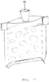
- the pouch 2 With the pouch 2 held in the open configuration by the fold formed in the bottom of the pouch 2, the pouch 2 can be filled with product via the or each nozzle 44.
- the pouch 2 may be used for packaging pet food, with a first fill nozzle 44 delivering a liquid, such as gravy, and a second fill nozzle 44 delivering solids, such as meat, to the pouch 2.
- a single nozzle 44 may be used to supply both liquid and solids to the pouch 2 by selectively connecting different supply lines/sources.
- the apparatus further comprises a heat-sealing apparatus, as shown in Figure 12 .
- the heat- sealing apparatus comprises a pair of jaw bars 46 (only a front jaw bar 46 is visible in Figure 12 ).
- the pouch 2 is introduced between the jaw bars 46 with the first layer 4 directed towards one of the jaw bars 46 and the second layer directed towards the other jaw bar 46.
- the jaw bars extend across the width of the pouch 2.
- the pouch 2 is positioned such that the jaw bars are adjacent and parallel to the top edge 14.
- the jaw bars 46 are movable relative to one another such that they can be brought into contact with the first and second layers 4, 6 thereby forcing the first and second layers 4, 6 towards one another in order to close the pouch 2.
- One or both of the jaw bars 46 are heated such that the first and second layers 4, 6 are welded to one another along a seal line 48 (see Figure 13 ) adjacent the top edge 14 in order to seal the pouch 2.
- the jaw bars 46 may be continuously heated or intermittently heated only when the jaw bars 46 are brought together.
- the shape of the fold formed in the bottom of the pouch 2 has been found to provide a stable geometry such that the fold is retained and does not readily spring back to its original position.
- An unstable fold which is liable to spring back can cause the contents of the pouch 2 to be ejected upwards into the region where the seal line 48 is formed. This can cause problems with the integrity of the seal since the heat-sealing apparatus may struggle to properly weld the first and second layers 4, 6 to one another in the presence of contaminants along the seal line 48. This can therefore lead to leakage of product from pouches.
- Pouches may be underfilled in order to reduce the risk of contaminants being present along the seal line; however, this increases material usage.
- the stable geometry provided by the fold disclosed herein allows the pouch 2 to be filled to a maximum level whilst ensuring the integrity of the seal and thereby minimizes material usage.
- the fold formed in the bottom of the pouch 2 can then be removed, as shown in Figure 13 . This ensures that multiple pouches 2 can be packaged together for efficient transportation and display.
- Figure 14 shows a flow chart of an exemplary method of filling a flat pouch according to the present disclosure.
- a lower portion of the pouch is folded relative to an upper portion about a fold line.
- a crease may be pre-formed between the lower portion and the upper portion which forms the fold line.
- the lower portion may be folded such that it extends perpendicularly to the upper portion.
- a guide may be inserted into the cavity of the pouch so as to prevent the upper portion from being deflected when the lower portion is folded relative to the upper portion.
- a central region of the lower portion is lifted to form a shaped fold with distal regions of the lower portion on either lateral side of the central region sloping downwards away from the central region.
- the shaped fold is configured to maintain the pouch in an open configuration in which first and second layers of the pouch are separated over a top edge to form an opening into a cavity of the pouch.
- the central region may be lifted by a fold forming plate, as described previously, which rotates and/or translates between a first stowed position and a second deployed position.
- the fold forming plate may also fold the lower portion about the fold line.
- the fold forming plate may fold and shape the lower portion in a single motion or may perform a first motion to fold the lower portion and a second motion to shape the fold.
- the pouch can then be filled with product via the opening.
- the various features of the apparatus described above may be implemented in separate modules or may be integrated into a single fill and seal machine. It will be appreciated that in other examples the apparatus may be an integral form-fill-seal machine which also manufactures the pouches themselves, rather than being provided with preformed pouches for filling and sealing.
- the crease 22 may be formed with the pouch 2 lying flat in a horizontal orientation on the female creasing platen 16.
- the pouch 2 may be held by the grippers 24a, 24b in a vertical orientation when the crease 22 is formed.
- the fold forming plate 34 may reliably form the fold in the bottom of the pouch 2 without requiring the preformed crease 22.
- the arrangement of the guide 30 may differ from that shown.
- the bifurcated section of the fingers 32a, 32b may extend only over a distance which is sufficient to receive the fold forming plate 34 therebetween as the fold forming plate 34 moves to the second, deployed position.
- the guide 30 may therefore have a body portion which extends further into the pouch 2 than shown.
- the body portion may extend to the level of the crease 22 or, if a preformed crease is not required, to where the lower portion 38 is folded. The body portion may therefore assist with the folding of the lower portion 38.
- the upper portion of the pouch 2 may be retained in any other way.
- external grippers may be used to hold the pouch 2 above the crease 22 and to maintain the upper portion in a vertical orientation. Such external grippers may be used in addition to or instead of the guide 30.
- a pair of external grippers may grasp the distal regions of the lower portion 38 and bend them downwards away from the central region. These external grippers may also lift the central region in the same action and thus may provide an alternative (or additional) means to the fold forming plate 34.
- upper and lower used herein are defined with respect to the opening of the pouch through which filling takes place and are not necessarily reflective of how the pouch may be subsequently oriented for display and/or use (e.g., when opened).
Landscapes
- Engineering & Computer Science (AREA)
- Mechanical Engineering (AREA)
- Supplying Of Containers To The Packaging Station (AREA)
Abstract
There is described a method of filling a flat pouch, the method comprising: folding a lower portion of the pouch relative to an upper portion about a fold line; forming a shaped fold by lifting a central region of the folded lower portion such that distal regions of the lower portion on either lateral side of the central region slope downwards away from the central region, wherein the shaped fold is configured to maintain the pouch in an open configuration in which first and second layers of the pouch are separated over a top edge to form an opening into a cavity of the pouch; and filling the cavity of the pouch with product via the opening. An associated apparatus for performing the method is also described.
Description
- Flexible pouches are commonly used for packaging edible and non-edible items and have particular application in the packaging of pet food. In its simplest form, a flat pouch (i.e., a three-side seal pouch) is formed by two layers of packaging material which are sealed along three sides. The pouch can be filled through the fourth side which is subsequently sealed to enclose the contents.
- Such pouches are often formed from packaging materials which have a laminated structure formed by multiple layers of different material which have desirable properties. For example, the packaging material may comprise an outer layer of Polyethylene Terephthalate (PET) which can be easily printed on, an aluminium foil (or metallised (e.g., MET-PET) film) layer which provides gas, aroma and water vapour barrier properties and a Polyethylene (PE) inner layer to provide a reliable seal. Such packaging materials are able to retain their form which can be beneficial during filling.
- Such packaging materials are typically more difficult to recycle. It is therefore desirable to use mono-materials to improve sustainability. However, these materials have poor dead-fold properties which can make filling more problematic.
- It is therefore desirable to provide a method and apparatus for filling a flat pouch which addresses or alleviates these issues.
- According to an aspect, there is provided a method of filling a flat pouch, the method comprising: folding a lower portion of the pouch relative to an upper portion about a fold line; forming a shaped fold by lifting a central region of the folded lower portion such that distal regions of the lower portion on either lateral side of the central region slope downwards away from the central region, wherein the shaped fold is configured to maintain the pouch in an open configuration in which first and second layers of the pouch are separated over a top edge to form an opening into a cavity of the pouch; and filling the cavity of the pouch with product via the opening.
- The method may further comprise forming a crease between the lower portion and the upper portion which forms the fold line.
- The lower portion may be folded such that it extends perpendicularly to the upper portion.
- The central region may be lifted by a fold forming plate which rotates and/or translates between a first stowed position and a second deployed position.
- The fold forming plate may also fold the lower portion about the fold line.
- The fold forming plate may rotate about an axis.
- The axis may be positioned above the level of the fold line.
- The first and second layers of the pouch may be separated over the top edge prior to forming the shaped fold.
- The first and second layers of the pouch may be separate by a pair of vacuum cups which engage the first and second layers respectively and move away from one another in order to open the pouch.
- The method may further comprise, prior to folding the lower portion, inserting a guide into the cavity of the pouch so as to prevent the upper portion from being deflected when the lower portion is folded relative to the upper portion.
- The guide may be configured to receive the fold forming plate when in the second deployed position.
- The guide may comprise a pair of fingers which are spaced laterally from one another such that the fold forming plate can be received therebetween.
- The fold line may be adjacent to a bottom of the cavity.
- Each of the first and second layers may be formed from a mono material.
- According to an aspect, there is provided a pouch filling apparatus configured to perform the method of described above.
- For a better understanding of the invention, and to show more clearly how it may be carried into effect, reference will now be made, by way of example, to the accompanying drawings, in which:
-
Figure 1 is a perspective view of a packaging pouch; -
Figure 2 is a side view of the pouch and showing a creasing assembly; -
Figure 3 is a perspective view of the pouch being held by a pair of grippers; -
Figure 4 is a perspective view of the pouch and an opening apparatus; -
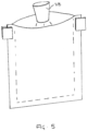
Figure 5 is a perspective view of the pouch and an air nozzle; -
Figure 6 is a perspective view of the pouch and showing a guide before insertion into the pouch; -
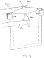
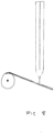
Figures 7 and8 are perspective and side views of the pouch and a fold forming plate in a stowed position; -
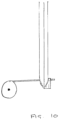
Figure 9 and10 are perspective and side views of the pouch and the fold forming plate in a deployed position; -
Figure 11 is a perspective view of the pouch and a filling nozzle; -
Figure 12 is a front view of the pouch and a heat-sealing apparatus; -
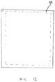
Figure 13 is a front view of the sealed pouch; and -
Figure 14 is a flowchart of a method. -
Figure 1 shows apackaging pouch 2 which may be used with the method and apparatus of the present disclosure. - The
pouch 2 is a flat pouch and comprises afirst layer 4 of flexible packaging material and asecond layer 6 of flexible packaging material. The first andsecond layers second layers - The first and
second layers bottom edge 8 and along opposing side edges 10a, 10b to form acavity 12 which is left open along a top edge 14 to allow filling. Thecavity 12 has a width W1 measured between the opposing side edges 10a, 10b and a depth D1 measured from the top edge 14 to thebottom edge 8. - The
pouch 2 may be filled using a method and apparatus according to the present disclosure, as will be described below. - As shown in
Figure 2 , the apparatus comprises a creasing assembly. The creasing assembly comprises afemale creasing platen 16 and amale creasing rule 20. Thefemale creasing platen 16 comprises agroove 20 which is sized to receive acorresponding rib 19 provided on themale creasing rule 18. As shown inFigure 2 , thepouch 2 is located between thefemale creasing platen 16 and themale creasing rule 18. Thepouch 2 is arranged such that thegroove 20 runs parallel to thebottom edge 8 and at or adjacent to the bottom of thecavity 12. - The
male creasing rule 18 is brought towards thefemale creasing platen 16 and therib 19 is received in thegroove 20, thereby forming acrease 22 extending across thepouch 2, as seen inFigure 3 . Thecrease 22 forms a fold line, as will be described further below. - As shown in
Figure 3 , the apparatus further comprises a pair of grippers 24a, 24b. The grippers 24a, 24b each comprise a pair of gripping jaws which are actuatable to selectively grip thepouch 2 against the first andsecond layers pouch 2 along the side edges 10a, 10b and adjacent the top edge 14. - As shown in
Figure 4 , the apparatus further comprises a pair of vacuum cups 26a, 26b which are provided onarms 27a, 27b. - The vacuum cups 26a, 26b are brought into contact with the first and
second layers second layers pouch 2 by separating the first andsecond layers second layers second layers - As shown in
Figure 5 , the apparatus may further comprise anair nozzle 28. Theair nozzle 28 blows a jet of air into thecavity 12 in order to further space the first andsecond layers cavity 12. - As shown in
Figure 6 , the apparatus further comprises aguide 30. Theguide 30 comprises a pair offingers fingers - With the
pouch 2 open, theguide 30 is inserted into thecavity 12. The outer width W3 corresponds to (i.e., is slightly smaller than) the width W1 of thecavity 12. Accordingly, thefingers cavity 12 and extend parallel to the side edges 10a, 10b. Theguide 30 is inserted such that thefingers Figure 7 . It will be appreciated that in other examples, thefingers common guide 30. - With the
fingers fold forming plate 34 is brought under thebottom edge 8 of thepouch 2, as shown inFigure 7 . Thefold forming plate 34 is pivotably mounted about anaxis 36. Theaxis 36 is located at or towards an edge of thefold forming plate 34 and is parallel but offset from a plane of thepouch 2. - The
fold forming plate 34 is rectangular and has a width W4 which is smaller than the inner width W2 between thefingers - The
fold forming plate 34 has a first, stowed position in which thefold forming plate 34 is angled downwards, as shown inFigures 7 and8 . For example, in the first position, thefold forming plate 34 may be angled downwards at 30 degrees from a horizontal direction (i.e., 120 degrees from a vertical direction; at the 4 o'clock position, as viewed inFigure 8 ). Thefold forming plate 34 has a second, deployed position in which thefold forming plate 34 is angled horizontally, as shown inFigures 9 and10 . In other examples, thefold forming plate 34 may be angled upwards in the second position. For example, in the second position, thefold forming plate 34 may be angled upwards at 30 degrees from the horizontal direction (i.e., 60 degrees from the vertical direction; at the 2 o'clock position). - In the first position, the
fold forming plate 34 is spaced frombottom edge 8 of thepouch 2. Thefold forming plate 34 is rotated about theaxis 36 towards the second position by a suitable actuator. During the transition from the first position to the second position, thefold forming plate 34 is brought into contact with thebottom edge 8 of thepouch 2. - The continued movement of the
fold forming plate 34 to the second position causes alower portion 38 of thepouch 2 to be folded about thecrease 22 into a horizontal orientation, as can be seen inFigure 9 . Thefingers pouch 2 and prevent the remainder of the pouch 2 (i.e., an upper portion) from being deflected by the action of thefold forming plate 34 and thus is maintained in a vertical orientation. Thelower portion 38 therefore extends perpendicularly to the remainder of thepouch 2. - The
axis 36 of thefold forming plate 34 is positioned above the level of thecrease 22 formed across thepouch 2, as depicted by line 37 inFigure 7 . Accordingly, as thefold forming plate 34 transitions from the first position to the second position, as well as folding thelower portion 38 about thecrease 22, thefold forming plate 34 also lifts a central region of thelower portion 38 upwards. - As described previously, the width W4 of the
fold forming plate 34 is smaller than the inner width W2 between thefingers fold forming plate 34 can be received between thefingers fold forming plate 34 can be received between thefingers lower portion 38. - Distal regions of the
lower portion 38 on either lateral side of the central region slope downwards away from the central region. As a result of the shape of thelower portion 38, the side edges 10a, 10b of thepouch 2 are drawn towards one another over a bottom portion of thepouch 2. To allow for this, thefingers - In other examples, the
fingers fold forming plate 34 moves to the second position. - In other examples, the
fold forming plate 34 may first rotate about theaxis 36 and may then translate upwards to lift the central region of thelower portion 38. - With the fold formed in the bottom of the
pouch 2, theguide 30 can be retracted to withdraw thefingers cavity 12 of thepouch 2 and thefold forming plate 34 can be removed, as shown inFigure 11 . Thefold forming plate 34 may be returned to the first, stowed position or removed entirely from the vicinity of thepouch 2. - The shape of the fold formed in the bottom of the
pouch 2 is effective in maintaining thepouch 2 in the open configuration with the first andsecond layers cavity 12. The vacuum cups 26a, 26b can therefore be disengaged from the first andsecond layers pouch 2. It will be appreciated that in other examples the vacuum cups 26a, 26b may be disengaged earlier in the process; for example, before or once thefingers guide 30 have been inserted into thecavity 12. Further, in other examples, the act of folding thelower portion 38 may be effective in separating the first andsecond layers pouch 2. - The shape of the fold formed in the
lower portion 38 of thepouch 2 has been found to provide a stable geometry such that the fold is retained even after removal of thefold forming plate 34. The fold is effectively retained even with sustainable mono-materials which typically have poor dead-fold properties and can thus spring back to their original position. - As shown in
Figure 11 , the apparatus further comprises one ormore fill nozzles 44. With thepouch 2 held in the open configuration by the fold formed in the bottom of thepouch 2, thepouch 2 can be filled with product via the or eachnozzle 44. For example, thepouch 2 may be used for packaging pet food, with afirst fill nozzle 44 delivering a liquid, such as gravy, and asecond fill nozzle 44 delivering solids, such as meat, to thepouch 2. In other examples, asingle nozzle 44 may be used to supply both liquid and solids to thepouch 2 by selectively connecting different supply lines/sources. - The apparatus further comprises a heat-sealing apparatus, as shown in
Figure 12 . The heat- sealing apparatus comprises a pair of jaw bars 46 (only afront jaw bar 46 is visible inFigure 12 ). Thepouch 2 is introduced between the jaw bars 46 with thefirst layer 4 directed towards one of the jaw bars 46 and the second layer directed towards theother jaw bar 46. The jaw bars extend across the width of thepouch 2. Thepouch 2 is positioned such that the jaw bars are adjacent and parallel to the top edge 14. The jaw bars 46 are movable relative to one another such that they can be brought into contact with the first andsecond layers second layers pouch 2. One or both of the jaw bars 46 are heated such that the first andsecond layers Figure 13 ) adjacent the top edge 14 in order to seal thepouch 2. The jaw bars 46 may be continuously heated or intermittently heated only when the jaw bars 46 are brought together. - As described previously, the shape of the fold formed in the bottom of the
pouch 2 has been found to provide a stable geometry such that the fold is retained and does not readily spring back to its original position. An unstable fold which is liable to spring back can cause the contents of thepouch 2 to be ejected upwards into the region where theseal line 48 is formed. This can cause problems with the integrity of the seal since the heat-sealing apparatus may struggle to properly weld the first andsecond layers seal line 48. This can therefore lead to leakage of product from pouches. Pouches may be underfilled in order to reduce the risk of contaminants being present along the seal line; however, this increases material usage. The stable geometry provided by the fold disclosed herein allows thepouch 2 to be filled to a maximum level whilst ensuring the integrity of the seal and thereby minimizes material usage. - With the
pouch 2 fully sealed, the fold formed in the bottom of thepouch 2 can then be removed, as shown inFigure 13 . This ensures thatmultiple pouches 2 can be packaged together for efficient transportation and display. -
Figure 14 shows a flow chart of an exemplary method of filling a flat pouch according to the present disclosure. - In a first step, S2, a lower portion of the pouch is folded relative to an upper portion about a fold line. A crease may be pre-formed between the lower portion and the upper portion which forms the fold line. The lower portion may be folded such that it extends perpendicularly to the upper portion. As described previously, a guide may be inserted into the cavity of the pouch so as to prevent the upper portion from being deflected when the lower portion is folded relative to the upper portion.
- In a second step, S4, a central region of the lower portion is lifted to form a shaped fold with distal regions of the lower portion on either lateral side of the central region sloping downwards away from the central region. The shaped fold is configured to maintain the pouch in an open configuration in which first and second layers of the pouch are separated over a top edge to form an opening into a cavity of the pouch.
- The central region may be lifted by a fold forming plate, as described previously, which rotates and/or translates between a first stowed position and a second deployed position. The fold forming plate may also fold the lower portion about the fold line. For example, the fold forming plate may fold and shape the lower portion in a single motion or may perform a first motion to fold the lower portion and a second motion to shape the fold.
- In a third step, S6, the pouch can then be filled with product via the opening.
- It will be appreciated that the method may be implemented using an apparatus as described previously.
- It will be appreciated that the method and apparatus may be modified from that described above.
- The various features of the apparatus described above may be implemented in separate modules or may be integrated into a single fill and seal machine. It will be appreciated that in other examples the apparatus may be an integral form-fill-seal machine which also manufactures the pouches themselves, rather than being provided with preformed pouches for filling and sealing.
- It will be appreciated that the
crease 22 may be formed with thepouch 2 lying flat in a horizontal orientation on thefemale creasing platen 16. Alternatively, thepouch 2 may be held by the grippers 24a, 24b in a vertical orientation when thecrease 22 is formed. In other examples, thefold forming plate 34 may reliably form the fold in the bottom of thepouch 2 without requiring the preformedcrease 22. - The arrangement of the
guide 30 may differ from that shown. For example, the bifurcated section of thefingers fold forming plate 34 therebetween as thefold forming plate 34 moves to the second, deployed position. Theguide 30 may therefore have a body portion which extends further into thepouch 2 than shown. For example, the body portion may extend to the level of thecrease 22 or, if a preformed crease is not required, to where thelower portion 38 is folded. The body portion may therefore assist with the folding of thelower portion 38. - In other examples, the upper portion of the
pouch 2 may be retained in any other way. For example, external grippers may be used to hold thepouch 2 above thecrease 22 and to maintain the upper portion in a vertical orientation. Such external grippers may be used in addition to or instead of theguide 30. - In other examples, a pair of external grippers may grasp the distal regions of the
lower portion 38 and bend them downwards away from the central region. These external grippers may also lift the central region in the same action and thus may provide an alternative (or additional) means to thefold forming plate 34. - The relative terms "upper" and "lower" used herein are defined with respect to the opening of the pouch through which filling takes place and are not necessarily reflective of how the pouch may be subsequently oriented for display and/or use (e.g., when opened).
Claims (15)
- A method of filling a flat pouch, the method comprising:folding a lower portion of the pouch relative to an upper portion about a fold line;forming a shaped fold by lifting a central region of the folded lower portion such that distal regions of the lower portion on either lateral side of the central region slope downwards away from the central region, wherein the shaped fold is configured to maintain the pouch in an open configuration in which first and second layers of the pouch are separated over a top edge to form an opening into a cavity of the pouch; andfilling the cavity of the pouch with product via the opening.
- The method of claim 1, further comprising: forming a crease between the lower portion and the upper portion which forms the fold line.
- The method of claim 1 or 2, wherein the lower portion is folded such that it extends perpendicularly to the upper portion.
- The method of any one of the preceding claims, wherein the central region is lifted by a fold forming plate which rotates and/or translates between a first stowed position and a second deployed position.
- The method of claim 4, wherein the fold forming plate also folds the lower portion about the fold line.
- The method of claim 4 or 5, wherein the fold forming plate rotates about an axis.
- The method of claim 6, wherein the axis is positioned above the level of the fold line.
- The method of any one of the preceding claims, wherein the first and second layers of the pouch are separated over the top edge prior to forming the shaped fold.
- The method of claim 8, wherein the first and second layers of the pouch are separate by a pair of vacuum cups which engage the first and second layers respectively and move away from one another in order to open the pouch.
- The method of any one of the preceding claims, further comprising, prior to folding the lower portion, inserting a guide into the cavity of the pouch so as to prevent the upper portion from being deflected when the lower portion is folded relative to the upper portion.
- The method of claim 10 when appended to claim 4, wherein the guide is configured to receive the fold forming plate when in the second deployed position.
- The method of claim 11, wherein the guide comprises a pair of fingers which are spaced laterally from one another such that the fold forming plate can be received therebetween.
- The method of any one of the preceding claims, wherein the fold line is adjacent to a bottom of the cavity.
- The method of any one of the preceding claims, wherein each of the first and second layers is formed from a mono material.
- A pouch filling apparatus configured to perform the method of any one of the preceding claims.
Priority Applications (6)
| Application Number | Priority Date | Filing Date | Title |
|---|---|---|---|
| EP23180169.7A EP4480836A1 (en) | 2023-06-19 | 2023-06-19 | A method and apparatus for filling a pouch |
| EP24732716.6A EP4727851A1 (en) | 2023-06-19 | 2024-06-19 | A method and apparatus for filling a pouch |
| CN202480039136.5A CN121311412A (en) | 2023-06-19 | 2024-06-19 | A method and apparatus for filling bags |
| AU2024311881A AU2024311881A1 (en) | 2023-06-19 | 2024-06-19 | A method and apparatus for filling a pouch |
| PCT/EP2024/067098 WO2024261059A1 (en) | 2023-06-19 | 2024-06-19 | A method and apparatus for filling a pouch |
| MX2025015395A MX2025015395A (en) | 2023-06-19 | 2025-12-17 | A method and apparatus for filling a pouch |
Applications Claiming Priority (1)
| Application Number | Priority Date | Filing Date | Title |
|---|---|---|---|
| EP23180169.7A EP4480836A1 (en) | 2023-06-19 | 2023-06-19 | A method and apparatus for filling a pouch |
Publications (1)
| Publication Number | Publication Date |
|---|---|
| EP4480836A1 true EP4480836A1 (en) | 2024-12-25 |
Family
ID=86899255
Family Applications (2)
| Application Number | Title | Priority Date | Filing Date |
|---|---|---|---|
| EP23180169.7A Pending EP4480836A1 (en) | 2023-06-19 | 2023-06-19 | A method and apparatus for filling a pouch |
| EP24732716.6A Pending EP4727851A1 (en) | 2023-06-19 | 2024-06-19 | A method and apparatus for filling a pouch |
Family Applications After (1)
| Application Number | Title | Priority Date | Filing Date |
|---|---|---|---|
| EP24732716.6A Pending EP4727851A1 (en) | 2023-06-19 | 2024-06-19 | A method and apparatus for filling a pouch |
Country Status (5)
| Country | Link |
|---|---|
| EP (2) | EP4480836A1 (en) |
| CN (1) | CN121311412A (en) |
| AU (1) | AU2024311881A1 (en) |
| MX (1) | MX2025015395A (en) |
| WO (1) | WO2024261059A1 (en) |
Citations (2)
| Publication number | Priority date | Publication date | Assignee | Title |
|---|---|---|---|---|
| DE3441947A1 (en) * | 1984-11-16 | 1986-05-28 | Robert Bosch Gmbh, 7000 Stuttgart | Method and apparatus for opening a flat bag |
| US20090232424A1 (en) * | 2008-03-11 | 2009-09-17 | Patrick Joseph Bierschenk | Method and apparatus for making a flat bottom pillow pouch |
-
2023
- 2023-06-19 EP EP23180169.7A patent/EP4480836A1/en active Pending
-
2024
- 2024-06-19 CN CN202480039136.5A patent/CN121311412A/en active Pending
- 2024-06-19 WO PCT/EP2024/067098 patent/WO2024261059A1/en not_active Ceased
- 2024-06-19 AU AU2024311881A patent/AU2024311881A1/en active Pending
- 2024-06-19 EP EP24732716.6A patent/EP4727851A1/en active Pending
-
2025
- 2025-12-17 MX MX2025015395A patent/MX2025015395A/en unknown
Patent Citations (2)
| Publication number | Priority date | Publication date | Assignee | Title |
|---|---|---|---|---|
| DE3441947A1 (en) * | 1984-11-16 | 1986-05-28 | Robert Bosch Gmbh, 7000 Stuttgart | Method and apparatus for opening a flat bag |
| US20090232424A1 (en) * | 2008-03-11 | 2009-09-17 | Patrick Joseph Bierschenk | Method and apparatus for making a flat bottom pillow pouch |
Also Published As
| Publication number | Publication date |
|---|---|
| AU2024311881A1 (en) | 2025-12-18 |
| CN121311412A (en) | 2026-01-09 |
| MX2025015395A (en) | 2026-04-01 |
| WO2024261059A1 (en) | 2024-12-26 |
| EP4727851A1 (en) | 2026-04-22 |
Similar Documents
| Publication | Publication Date | Title |
|---|---|---|
| US7017796B2 (en) | Method of manufacturing paper packaging container and paper packaging container | |
| US10850887B2 (en) | Carton sleeve, carton and method for producing a carton | |
| CN102015276B (en) | Improved method and apparatus for making flat-bottomed pillow-shaped bags | |
| CN103764509B (en) | Improved method and apparatus for making a flat bottom pillow pouch | |
| KR20140010005A (en) | Production method for packaging container and packaging container | |
| EP2592017B1 (en) | Resealable tetrahedral packaging | |
| NO338817B1 (en) | Cardboard box with folded extension tips | |
| JP5130586B2 (en) | Paper container | |
| AU2024311881A1 (en) | A method and apparatus for filling a pouch | |
| JP3809694B2 (en) | Free-standing bag for fluid packaging | |
| CA3006048C (en) | Bottom gusset package with folded gusset | |
| JP3135179U (en) | Stick-shaped packaging bag | |
| WO2023042853A1 (en) | Blank and paper container for liquids employing same | |
| JP2009073550A (en) | Pouch container having spout, and its bag-making and filling method | |
| US3148489A (en) | Method of producing a filled package | |
| US3280532A (en) | Method of closing and forming pliable containers filled with a liquid | |
| US11192678B2 (en) | Closures for carton board packaging of gable top type and sealing thereof | |
| JP5924874B2 (en) | Packaging container and its manufacturing method | |
| JP3188892U (en) | Packaging box | |
| JP5380716B2 (en) | Pouch container with spout | |
| KR102061190B1 (en) | Gusset container | |
| JP6866415B2 (en) | Paper container | |
| CN108602576A (en) | It is used to form the building mortion for being packaged as finished product packing box and method, the folding unit for the sealing packaging box for being used to form pourable food and a kind of packing box | |
| JP6684157B2 (en) | Package | |
| JP2022007285A (en) | Food packaging bag and food packaging body |
Legal Events
| Date | Code | Title | Description |
|---|---|---|---|
| PUAI | Public reference made under article 153(3) epc to a published international application that has entered the european phase |
Free format text: ORIGINAL CODE: 0009012 |
|
| STAA | Information on the status of an ep patent application or granted ep patent |
Free format text: STATUS: THE APPLICATION HAS BEEN PUBLISHED |
|
| AK | Designated contracting states |
Kind code of ref document: A1 Designated state(s): AL AT BE BG CH CY CZ DE DK EE ES FI FR GB GR HR HU IE IS IT LI LT LU LV MC ME MK MT NL NO PL PT RO RS SE SI SK SM TR |
|
| STAA | Information on the status of an ep patent application or granted ep patent |
Free format text: STATUS: REQUEST FOR EXAMINATION WAS MADE |
|
| 17P | Request for examination filed |
Effective date: 20250625 |