EP4480827A1 - Aircraft propulsion assembly having a jet engine, a pylon and an extinguishing system - Google Patents
Aircraft propulsion assembly having a jet engine, a pylon and an extinguishing system Download PDFInfo
- Publication number
- EP4480827A1 EP4480827A1 EP24178688.8A EP24178688A EP4480827A1 EP 4480827 A1 EP4480827 A1 EP 4480827A1 EP 24178688 A EP24178688 A EP 24178688A EP 4480827 A1 EP4480827 A1 EP 4480827A1
- Authority
- EP
- European Patent Office
- Prior art keywords
- extinguishing
- propulsion assembly
- support ring
- extinguishing system
- jet engine
- Prior art date
- Legal status (The legal status is an assumption and is not a legal conclusion. Google has not performed a legal analysis and makes no representation as to the accuracy of the status listed.)
- Pending
Links
Images


Classifications
-
- B—PERFORMING OPERATIONS; TRANSPORTING
- B64—AIRCRAFT; AVIATION; COSMONAUTICS
- B64D—EQUIPMENT FOR FITTING IN OR TO AIRCRAFT; FLIGHT SUITS; PARACHUTES; ARRANGEMENT OR MOUNTING OF POWER PLANTS OR PROPULSION TRANSMISSIONS IN AIRCRAFT
- B64D27/00—Arrangement or mounting of power plants in aircraft; Aircraft characterised by the type or position of power plants
- B64D27/40—Arrangements for mounting power plants in aircraft
- B64D27/402—Arrangements for mounting power plants in aircraft comprising box like supporting frames, e.g. pylons or arrangements for embracing the power plant
-
- B—PERFORMING OPERATIONS; TRANSPORTING
- B64—AIRCRAFT; AVIATION; COSMONAUTICS
- B64D—EQUIPMENT FOR FITTING IN OR TO AIRCRAFT; FLIGHT SUITS; PARACHUTES; ARRANGEMENT OR MOUNTING OF POWER PLANTS OR PROPULSION TRANSMISSIONS IN AIRCRAFT
- B64D27/00—Arrangement or mounting of power plants in aircraft; Aircraft characterised by the type or position of power plants
- B64D27/40—Arrangements for mounting power plants in aircraft
-
- A—HUMAN NECESSITIES
- A62—LIFE-SAVING; FIRE-FIGHTING
- A62C—FIRE-FIGHTING
- A62C3/00—Fire prevention, containment or extinguishing specially adapted for particular objects or places
- A62C3/02—Fire prevention, containment or extinguishing specially adapted for particular objects or places for area conflagrations, e.g. forest fires, subterranean fires
- A62C3/0228—Fire prevention, containment or extinguishing specially adapted for particular objects or places for area conflagrations, e.g. forest fires, subterranean fires with delivery of fire extinguishing material by air or aircraft
- A62C3/0242—Fire prevention, containment or extinguishing specially adapted for particular objects or places for area conflagrations, e.g. forest fires, subterranean fires with delivery of fire extinguishing material by air or aircraft by spraying extinguishants from the aircraft
-
- A—HUMAN NECESSITIES
- A62—LIFE-SAVING; FIRE-FIGHTING
- A62C—FIRE-FIGHTING
- A62C3/00—Fire prevention, containment or extinguishing specially adapted for particular objects or places
- A62C3/07—Fire prevention, containment or extinguishing specially adapted for particular objects or places in vehicles, e.g. in road vehicles
- A62C3/08—Fire prevention, containment or extinguishing specially adapted for particular objects or places in vehicles, e.g. in road vehicles in aircraft
-
- A—HUMAN NECESSITIES
- A62—LIFE-SAVING; FIRE-FIGHTING
- A62C—FIRE-FIGHTING
- A62C35/00—Permanently-installed equipment
- A62C35/58—Pipe-line systems
- A62C35/68—Details, e.g. of pipes or valve systems
-
- B—PERFORMING OPERATIONS; TRANSPORTING
- B64—AIRCRAFT; AVIATION; COSMONAUTICS
- B64C—AEROPLANES; HELICOPTERS
- B64C11/00—Propellers, e.g. of ducted type; Features common to propellers and rotors for rotorcraft
- B64C11/001—Shrouded propellers
-
- B—PERFORMING OPERATIONS; TRANSPORTING
- B64—AIRCRAFT; AVIATION; COSMONAUTICS
- B64D—EQUIPMENT FOR FITTING IN OR TO AIRCRAFT; FLIGHT SUITS; PARACHUTES; ARRANGEMENT OR MOUNTING OF POWER PLANTS OR PROPULSION TRANSMISSIONS IN AIRCRAFT
- B64D27/00—Arrangement or mounting of power plants in aircraft; Aircraft characterised by the type or position of power plants
- B64D27/02—Aircraft characterised by the type or position of power plants
- B64D27/16—Aircraft characterised by the type or position of power plants of jet type
- B64D27/18—Aircraft characterised by the type or position of power plants of jet type within, or attached to, wings
-
- F—MECHANICAL ENGINEERING; LIGHTING; HEATING; WEAPONS; BLASTING
- F02—COMBUSTION ENGINES; HOT-GAS OR COMBUSTION-PRODUCT ENGINE PLANTS
- F02C—GAS-TURBINE PLANTS; AIR INTAKES FOR JET-PROPULSION PLANTS; CONTROLLING FUEL SUPPLY IN AIR-BREATHING JET-PROPULSION PLANTS
- F02C7/00—Features, components parts, details or accessories, not provided for in, or of interest apart form groups F02C1/00 - F02C6/00; Air intakes for jet-propulsion plants
- F02C7/24—Heat or noise insulation
- F02C7/25—Fire protection or prevention
-
- B—PERFORMING OPERATIONS; TRANSPORTING
- B64—AIRCRAFT; AVIATION; COSMONAUTICS
- B64D—EQUIPMENT FOR FITTING IN OR TO AIRCRAFT; FLIGHT SUITS; PARACHUTES; ARRANGEMENT OR MOUNTING OF POWER PLANTS OR PROPULSION TRANSMISSIONS IN AIRCRAFT
- B64D45/00—Aircraft indicators or protectors not otherwise provided for
- B64D2045/009—Fire detection or protection; Erosion protection, e.g. from airborne particles
Definitions
- the present invention relates to the general field of aircraft propulsion assembly. It particularly relates to the extinguishing system which is implemented in the propulsion assembly. It also relates to an aircraft equipped with such a propulsion assembly.
- a propulsion assembly of the prior art is fastened beneath a wing of an aircraft that has a jet engine and an attachment pylon via which the jet engine is fastened beneath the wing.
- the length of the piping is therefore quite significant.
- a large amount of extinguishing agent in the extinguishing bottle is needed to ensure the system operation.
- the volume of the bottle is therefore significant, as the weight of the system.
- An object of the present invention is to propose a propulsion assembly for an aircraft, said propulsion assembly having:
- said extinguishing system is located in a front position relative to said rigid structure, the extinguishing system being positioned between said rigid structure and said jet engine.
- said jet engine comprises a fan casing and a central casing both extending around a longitudinal axis.
- said rigid structure takes the form of a box that has a front wall and an upper spar extending forwardly with respect to the front wall. Said extinguishing system is positioned between the upper spar, the front wall and the fan casing.
- said extinguishing system comprises:
- each support ring comprises locking means for removably fixing one of said at least one extinguishing bottle on said support ring, said locking means being arranged to allow locking and unlocking of said extinguishing bottle on said support ring.
- the invention also proposes an aircraft having a propulsion assembly according to the preceding variants.
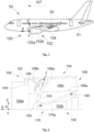
- Fig. 1 shows an aircraft 50 that has a fuselage 51 and a wing 52 on each side of the fuselage 51. At least one propulsion assembly 100 is fastened beneath each wing 52 and it comprises a jet engine 102 and an attachment pylon 104.
- X denotes the longitudinal axis of the propulsion assembly 100 corresponding to a longitudinal axis X of the jet engine 102.
- Y denotes the transverse axis of the propulsion assembly 100 corresponding to a transverse axis of the jet engine 102, this axis being horizontal when the aircraft is on the ground, and
- Z denotes the vertical axis or vertical height of the propulsion assembly 100 corresponding to a vertical axis of the jet engine 102, this axis being vertical when the aircraft is on the ground, these three axis X, Y and Z being mutually orthogonal.
- the terms “front” and “rear” are to be considered relative to a direction of forward movement of the aircraft when the jet engine 102 is in operation, this direction being schematically shown by the arrow 107.
- the jet engine 102 has also a vertical median plane P (XZ) passing through the longitudinal axis X and the vertical axis Z.
- the jet engine 102 has at the front, a fan casing 102a surrounding an annular fan duct in which a fan rotates and at the rear of the fan casing 102a, a central casing 102b of smaller size, enclosing the core of the jet engine 102.
- the fan casing 102a and the central casing 102b are around the longitudinal axis X.
- the propulsion assembly 100 has also a nacelle 102a inside which the jet engine 102 is installed.
- Fig. 2 shows the propulsion assembly 100 with the jet engine 102 and the attachment pylon 104 via which the jet engine 102 is fastened to the wing 52.
- the attachment pylon 104 is shown here by its rigid structure 106, which is also called the primary structure, and which is fastened beneath the wing 52.
- the rigid structure 106 extends along the longitudinal axis X between a front end and a rear end and takes the form of a box that has a lower spar 106a, an upper spar 106b, two lateral walls 106c and a frontal wall 106d which are fixed together to realize the rigid structure 106.
- the front wall 106d is oriented towards the front of the aircraft 50.
- a lateral wall 106c is arranged on each side of the vertical median plane P.
- the upper spar 106b is above the lateral walls 106c and the lower spar 106a is beneath the lateral walls 106c.
- the upper spar 106b extends forwardly in respect to the front wall 106d, it means that the upper spar 106b has a front end that is far from the front wall 106d in the forward direction F.
- the propulsion assembly 100 comprises a reaction device 170 for reacting the thrust forces generated by the jet engine 102.
- reaction device 170 comprises two reaction rods 170a disposed on either side of the median plane P and articulated, on the one hand, at the front, on the central casing 102b, and, on the other hand, at the rear, on the rigid structure 106 for example on the lower spar 106a thanks to appropriate fittings that are not described in details because they are not a part of the invention and a man skilled in the art would be able to implement the fittings known from the prior art.
- the propulsion assembly 100 comprises also a rear attachment 180 between the rigid structure 106, in this case the lower spar 106a, and a rear upper part of the central casing 102b.
- the rear attachment 180 is not described in detail because it is not a part of the invention and a man skilled in the art would be able to implement it from the prior art.
- the propulsion assembly 100 also comprises a front engine attachment 152 which is fixed between an upper area 103 of the fan casing 102a and the front end of the upper spar 106b.
- the propulsion assembly 100 comprises a complementary front engine attachment 153 fixed between an upper area 105 of the central casing 102b and a lower end of the front wall 106d. With such arrangement, the sizes of the attachments are reduced and allows an aerodynamic optimization by reducing the size of the fairing of the nacelle.
- Fig. 3 shows an example embodiment of the front engine attachment 152.
- the front engine attachment 152 comprises a lever 154 which is mounted articulated on the front end of the upper spar 106b at the vertical median plane P.
- the front end of the upper spar 106b comprises for example a front cylinder, the axis of which is in the vertical median plane P and parallel to the longitudinal axis X and the lever 154 comprises a front hole in which the front cylinder is inserted in an articulated manner.
- the lever 154 On each side of the vertical median plane P, the lever 154 comprises an end 154a-b which is mounted articulated on the upper area 103 of the fan casing 102a. These two ends 154a-b are symmetrical in respect to the vertical median plane P.
- a female clevis 159a-b is fixed to the upper area 103 of the fan casing 102a and said end 154a-b of the lever 154 is a male clevis mounted articulated in said female clevis 159a-b and maintained by an articulation axis inserted in an articulation hole of the end 154a-b.
- Articulation holes of the female clevis 159a-b and articulation axis are parallel to the longitudinal axis X.
- Fig. 4 shows an example embodiment of the complementary front engine attachment 153.
- the complementary front engine attachment 153 comprises two fitting assemblies 452a-b, each one comprising, at the vertical median plane P, a first articulation point 454a to realize an articulation with the lower end of the front wall 106d, and on each side of the vertical median plane P, a second articulation point 454b-c to realize an articulation with the upper area 105 of the central casing 102b.
- Each fitting assembly 452a-b is globally in a plane perpendicular to the longitudinal axis X and each articulation point 454a-c takes the form of a pivot link, the axis of rotation of which is globally parallel to the longitudinal axis X.
- Each articulation 454a-c of one fitting assembly 452a-b is coaxial with one articulation 454a-c of the other fitting assembly 452a-b.
- each articulation 454a-c is realized by the combination of a first articulation hole 455 passing through the corresponding fitting assembly 452a-b and a second articulation hole 457 passing through the lower end of the front wall 106d or the upper area 105 of the central casing 102b.
- a first articulation hole 455 of one fitting assembly 452a-b is aligned with a first articulation hole 455 of the other fitting assembly 452b-a and a second articulation hole 457 of the lower end of the front wall 106d or of the upper area 105 of the central casing 102b.
- the propulsion assembly 100 comprises also for each second articulation hole 457, an articulation axis 459 which is inserted in said second articulation hole 457 and in the corresponding first articulation holes 455 of the two fitting assemblies 452a-b.
- the axis of each articulation axis 459 is globally parallel to the longitudinal axis X.
- each fitting assembly 452a-b takes the form of a triangle, and a fitting assembly 452a-b is arranged on each side of the lower end of the front wall 106d.
- the front engine attachment 152 reacts to the lateral loads only (parallel to the lateral axis Y) and the complementary front engine attachment 153 reacts to the lateral loads (parallel to the lateral axis Y) and to vertical loads (parallel to the vertical axis Z).
- the propulsion assembly 100 comprises a main rod 156 fixed between the upper spar 106b and the front wall 106d. Each end of the main rod 156 is mounted in an articulated manner respectively to the upper spar 106b and to the front wall 106d.
- Figs. 2 , 5 and 6 show the propulsion assembly according to the invention.
- the propulsion assembly 100 further comprises an extinguishing system 2 which is located in a front position relative to said rigid structure 106.
- the front position is taken according to the horizontal axis X and the forward direction 107. More particularly, the extinguishing system 2 is positioned between the rigid structure 106 and the jet engine 102.
- the jet engine 102 comprises a fan casing 102a and a central casing 102b both extending around a longitudinal axis (X).
- the fan casing 102a and the central casing 102b have a vertical median plan P passing through the longitudinal axis X.
- the rigid structure 106 takes the form of a box that has a front wall 106d and an upper spar 106b extending forwardly with respect to the front wall 106d.
- the extinguishing system 2 is positioned between the upper spar 106b, the front wall 106d and the fan casing 102a.
- the length of the piping from the extinguishing bottle 21 towards the nozzle 22 (as described below) can be reduced. Having shorter piping may enable to reduce the needed extinguishing agent volume and consequently to decrease the size and the weight of the extinguishing bottles 21.
- having the extinguishing system 2 in this area allows to have a cold air ventilation of the extinguishing bottles 21 thanks to an air intake from the fan.
- the extinguishing system 2 comprises:
- each pipe 23 is connected between an extinguishing bottle 21 and a set (not illustrated) of nozzles 22.
- the length of the pipes 23 are thus optimized so the overall weight of the system can also be optimized.
- the extinguishing system 2 comprises a supporting device 24 having at least one support ring 241 on which the at least one extinguishing bottle 21 is held and removably fixed.
- Each support ring 241 is fixed to a base 242, which base 242 being fixed to the upper spar 106b or to the front wall 106d.
- the extinguishing system 2 comprises two extinguishing bottles 21 but it is obvious that one bottle or more than two bottles 21 can be implemented without departing from the general principle of invention. It is understood that the number of support ring 241 would thus be adapted to the number of bottles 21.
- Each extinguishing bottle 21 is held on a support ring 241. It means that the extinguishing bottle 21 is received in the support ring 241 or that the extinguishing bottle 21 is set on the support ring 241. In other words, each extinguishing bottle 21 is supported by a support ring 241.
- the base 242 is fixed to the front wall 106d of the rigid structure 106.
- the base 242 extends globally vertically, that means globally parallelly to the vertical axis Z. Consequently, the extinguishing bottles 21 are globally vertically aligned one above the others.
- the base 242 is fixed to the upper spar 106b of the rigid structure 106.
- the base 242 extends globally horizontally, that means globally parallelly to the horizontal axis X. Consequently, the extinguishing bottles 21 are globally horizontally aligned one next to the others.
- the extinguishing system 2 is positioned close to the critical fire area (that is to say close to the jet engine 102) and is reliably fixed to the rigid structure 106.
- the supporting device 24 comprises a side panel 243 extending globally perpendicularly to the base 242.
- the side panel 243 is fixed to the upper spar 106b or to the front wall 106d. More particularly, when the base 242 is fixed to the front wall 106d, the side panel 243 is thus fixed to the upper spar 106b (as illustrated). When the base 242 is fixed to the upper spar 106b, the side panel 243 is thus fixed to the front wall 106d (not illustrated).
- the side panel 243 acts as a reinforcement to ensure the reliable fixing of the extinguishing system 2 to the rigid structure 106.
- each support ring 241 comprises a cutout 241a allowing the extinguishing bottle 21 to be installed and removed from the support ring 241. More particularly, each support ring 241 surrounds at least a portion of the extinguishing bottle 21 held in the support ring 241.
- the cutout 241a allows the extinguishing bottle 21 to be installed and removed from the support ring 241 by a movement of the extinguishing bottle 21 relative to the supporting ring 241 parallel to a horizontal plan XY.
- the extinguishing bottle 21 can be installed and removed from the support ring by a side movement of the extinguishing bottle 21.
- each support ring 241 comprises locking means 25 for removably fixing one of said at least one extinguishing bottle 21 on the support ring 241.
- the locking means 25 are arranged to allow locking and unlocking of the extinguishing bottle 21on the support ring 241.
- each extinguishing bottle 21 is removably fixed to the support ring 241 thanks to removable locking means 25.
- the removable locking means 25 can, for example, take the form of a bolt or a quick-release fastener.
Landscapes
- Engineering & Computer Science (AREA)
- Aviation & Aerospace Engineering (AREA)
- Business, Economics & Management (AREA)
- Health & Medical Sciences (AREA)
- Public Health (AREA)
- Emergency Management (AREA)
- Chemical & Material Sciences (AREA)
- Combustion & Propulsion (AREA)
- Forests & Forestry (AREA)
- Life Sciences & Earth Sciences (AREA)
- Ecology (AREA)
- Biodiversity & Conservation Biology (AREA)
- Mechanical Engineering (AREA)
- General Engineering & Computer Science (AREA)
- Structures Of Non-Positive Displacement Pumps (AREA)
Abstract
- a jet engine (102),
- an attachment pylon (104) having a rigid structure (106), and
- an extinguishing system (2),
Description
- The present invention relates to the general field of aircraft propulsion assembly. It particularly relates to the extinguishing system which is implemented in the propulsion assembly. It also relates to an aircraft equipped with such a propulsion assembly.
- A propulsion assembly of the prior art is fastened beneath a wing of an aircraft that has a jet engine and an attachment pylon via which the jet engine is fastened beneath the wing.
- Due to the design of attachment pylon of the prior art, standard extinguishing systems are installed at the rear of the attachment pylon above the aerodynamic fairing of the attachment and below the wing. They are usually attached to the rigid structure of the pylon or to the wing intrados. As the extinguishing agent of the extinguishing system needs to be ducted towards nozzles located inside the fire area, a common solution is to implement a pipe routing along the pylon from the extinguishing bottle location towards the nozzles. However, the extinguishing bottles are installed at the rear of the rigid structure whereas the nozzles are positioned at the front of the rigid structure, closer to the jet engine.
- The length of the piping is therefore quite significant. As a result, a large amount of extinguishing agent in the extinguishing bottle is needed to ensure the system operation. The volume of the bottle is therefore significant, as the weight of the system.
- There is therefore a need to provide an extinguishing system that at least partially overcomes the aforementioned drawbacks.
- An object of the present invention is to propose a propulsion assembly for an aircraft, said propulsion assembly having:
- a jet engine,
- an attachment pylon having a rigid structure, and
- an extinguishing system.
- According to the invention, said extinguishing system is located in a front position relative to said rigid structure, the extinguishing system being positioned between said rigid structure and said jet engine.
- With such an arrangement, the length of the piping from the extinguishing bottle towards the nozzle (as described below) can be reduced. Having shorter piping may enable to reduce the extinguishing agent volume needed and consequently to decrease the size and the weight of the extinguishing bottles. In addition, having the extinguishing system in this area allows to have a cold air ventilation of the extinguishing bottles thanks to an air intake from the fan. Advantageously, said jet engine comprises a fan casing and a central casing both extending around a longitudinal axis. Moreover, said rigid structure takes the form of a box that has a front wall and an upper spar extending forwardly with respect to the front wall. Said extinguishing system is positioned between the upper spar, the front wall and the fan casing. Advantageously, said extinguishing system comprises:
- at least one extinguishing bottle containing an extinguishing agent,
- at least one nozzle positioned in a critical fire area of said propulsion assembly, and
- pipes, each pipe having a first end connected to the at least one extinguishing bottle and a second end connected to said at least one nozzle for delivering the extinguishing agent. Advantageously, said extinguishing system comprises a supporting device having at least one support ring on which the at least one extinguishing bottle is held and removably fixed, each support ring being fixed to a base, the base being fixed to the upper spar or to the front wall. Advantageously, said supporting device comprises a side panel extending globally perpendicularly to the base, the side panel being fixed to the upper spar or to the front wall. Advantageously, each support ring comprises a cutout allowing said extinguishing bottle to be installed and removed from the support ring.
- Advantageously, each support ring comprises locking means for removably fixing one of said at least one extinguishing bottle on said support ring, said locking means being arranged to allow locking and unlocking of said extinguishing bottle on said support ring.
- The invention also proposes an aircraft having a propulsion assembly according to the preceding variants.
- The abovementioned features of the invention, along with others, will become more clearly apparent upon reading the following description of one exemplary embodiment, said description being given with reference to the appended drawings, in which:
-
Fig. 1 is a side view of an aircraft according to the invention, -
Fig. 2 is a schematic view of a propulsion assembly according to the invention, -
Fig. 3 is a perspective view of an example of a front engine attachment used in the propulsion assembly according to the invention, -
Fig. 4 is a perspective view of an example of a complementary front engine attachment used in the propulsion assembly according to the invention, -
Fig. 5 is a detailed view offigure 2 , and -
Fig. 6 is a perspective view of an extinguishing system configured to be implemented in the propulsion assembly of the invention. -
Fig. 1 shows anaircraft 50 that has afuselage 51 and awing 52 on each side of thefuselage 51. At least onepropulsion assembly 100 is fastened beneath eachwing 52 and it comprises ajet engine 102 and anattachment pylon 104. - By convention, X denotes the longitudinal axis of the
propulsion assembly 100 corresponding to a longitudinal axis X of thejet engine 102. Moreover, Y denotes the transverse axis of thepropulsion assembly 100 corresponding to a transverse axis of thejet engine 102, this axis being horizontal when the aircraft is on the ground, and Z denotes the vertical axis or vertical height of thepropulsion assembly 100 corresponding to a vertical axis of thejet engine 102, this axis being vertical when the aircraft is on the ground, these three axis X, Y and Z being mutually orthogonal. - Moreover, the terms "front" and "rear" are to be considered relative to a direction of forward movement of the aircraft when the
jet engine 102 is in operation, this direction being schematically shown by thearrow 107. Thejet engine 102 has also a vertical median plane P (XZ) passing through the longitudinal axis X and the vertical axis Z. - The
jet engine 102 has at the front, afan casing 102a surrounding an annular fan duct in which a fan rotates and at the rear of thefan casing 102a, acentral casing 102b of smaller size, enclosing the core of thejet engine 102. Thefan casing 102a and thecentral casing 102b are around the longitudinal axis X. - The
propulsion assembly 100 has also anacelle 102a inside which thejet engine 102 is installed. -
Fig. 2 shows thepropulsion assembly 100 with thejet engine 102 and theattachment pylon 104 via which thejet engine 102 is fastened to thewing 52. Theattachment pylon 104 is shown here by itsrigid structure 106, which is also called the primary structure, and which is fastened beneath thewing 52. - The
rigid structure 106 extends along the longitudinal axis X between a front end and a rear end and takes the form of a box that has alower spar 106a, anupper spar 106b, twolateral walls 106c and afrontal wall 106d which are fixed together to realize therigid structure 106. Thefront wall 106d is oriented towards the front of theaircraft 50. Alateral wall 106c is arranged on each side of the vertical median plane P. Theupper spar 106b is above thelateral walls 106c and thelower spar 106a is beneath thelateral walls 106c. - The
upper spar 106b extends forwardly in respect to thefront wall 106d, it means that theupper spar 106b has a front end that is far from thefront wall 106d in the forward direction F. In the present embodiment, thepropulsion assembly 100 comprises areaction device 170 for reacting the thrust forces generated by thejet engine 102. Here thereaction device 170 comprises tworeaction rods 170a disposed on either side of the median plane P and articulated, on the one hand, at the front, on thecentral casing 102b, and, on the other hand, at the rear, on therigid structure 106 for example on thelower spar 106a thanks to appropriate fittings that are not described in details because they are not a part of the invention and a man skilled in the art would be able to implement the fittings known from the prior art. - In the present embodiment, the
propulsion assembly 100 comprises also arear attachment 180 between therigid structure 106, in this case thelower spar 106a, and a rear upper part of thecentral casing 102b. Therear attachment 180 is not described in detail because it is not a part of the invention and a man skilled in the art would be able to implement it from the prior art. Thepropulsion assembly 100 also comprises afront engine attachment 152 which is fixed between anupper area 103 of thefan casing 102a and the front end of theupper spar 106b. At the same time, thepropulsion assembly 100 comprises a complementaryfront engine attachment 153 fixed between anupper area 105 of thecentral casing 102b and a lower end of thefront wall 106d. With such arrangement, the sizes of the attachments are reduced and allows an aerodynamic optimization by reducing the size of the fairing of the nacelle. - It is understood that several solutions can be implemented to obtain the
front engine attachment 152 and the complementaryfront engine attachment 153. Nevertheless, examples of each of these attachments are described below. -
Fig. 3 shows an example embodiment of thefront engine attachment 152. In this example, thefront engine attachment 152 comprises alever 154 which is mounted articulated on the front end of theupper spar 106b at the vertical median plane P. To this end, the front end of theupper spar 106b comprises for example a front cylinder, the axis of which is in the vertical median plane P and parallel to the longitudinal axis X and thelever 154 comprises a front hole in which the front cylinder is inserted in an articulated manner. - On each side of the vertical median plane P, the
lever 154 comprises anend 154a-b which is mounted articulated on theupper area 103 of thefan casing 102a. These two ends 154a-b are symmetrical in respect to the vertical median plane P. - To this end, for each
end 154a-b of thelever 154, afemale clevis 159a-b is fixed to theupper area 103 of thefan casing 102a and saidend 154a-b of thelever 154 is a male clevis mounted articulated in saidfemale clevis 159a-b and maintained by an articulation axis inserted in an articulation hole of theend 154a-b. Articulation holes of thefemale clevis 159a-b and articulation axis are parallel to the longitudinal axis X. -
Fig. 4 shows an example embodiment of the complementaryfront engine attachment 153. In this example, the complementaryfront engine attachment 153 comprises twofitting assemblies 452a-b, each one comprising, at the vertical median plane P, afirst articulation point 454a to realize an articulation with the lower end of thefront wall 106d, and on each side of the vertical median plane P, asecond articulation point 454b-c to realize an articulation with theupper area 105 of thecentral casing 102b. - Each
fitting assembly 452a-b is globally in a plane perpendicular to the longitudinal axis X and eacharticulation point 454a-c takes the form of a pivot link, the axis of rotation of which is globally parallel to the longitudinal axis X. Eacharticulation 454a-c of onefitting assembly 452a-b is coaxial with onearticulation 454a-c of the otherfitting assembly 452a-b. - To this end, each
articulation 454a-c is realized by the combination of afirst articulation hole 455 passing through the correspondingfitting assembly 452a-b and asecond articulation hole 457 passing through the lower end of thefront wall 106d or theupper area 105 of thecentral casing 102b. - In position, a
first articulation hole 455 of onefitting assembly 452a-b is aligned with afirst articulation hole 455 of the otherfitting assembly 452b-a and asecond articulation hole 457 of the lower end of thefront wall 106d or of theupper area 105 of thecentral casing 102b. Thepropulsion assembly 100 comprises also for eachsecond articulation hole 457, anarticulation axis 459 which is inserted in saidsecond articulation hole 457 and in the corresponding first articulation holes 455 of the twofitting assemblies 452a-b. The axis of eacharticulation axis 459 is globally parallel to the longitudinal axis X. - In this example, each
fitting assembly 452a-b takes the form of a triangle, and afitting assembly 452a-b is arranged on each side of the lower end of thefront wall 106d. - According to a specific arrangement, the
front engine attachment 152 reacts to the lateral loads only (parallel to the lateral axis Y) and the complementaryfront engine attachment 153 reacts to the lateral loads (parallel to the lateral axis Y) and to vertical loads (parallel to the vertical axis Z). - In addition, the axial moment Mx is sustained by the
front engine attachment 152 and the complementaryfront engine attachment 153 thanks to the lateral loads acting on thefan casing 102a and the lateral loads acting on thecentral casing 102b. The load transfer from thejet engine 102 to theattachment pylon 104 through this engine mount concept is isostatic. Preferably, in order to reinforce theupper spar 106b, thepropulsion assembly 100 comprises amain rod 156 fixed between theupper spar 106b and thefront wall 106d. Each end of themain rod 156 is mounted in an articulated manner respectively to theupper spar 106b and to thefront wall 106d. -
Figs. 2 ,5 and6 show the propulsion assembly according to the invention. Thepropulsion assembly 100 further comprises anextinguishing system 2 which is located in a front position relative to saidrigid structure 106. The front position is taken according to the horizontal axis X and theforward direction 107. More particularly, the extinguishingsystem 2 is positioned between therigid structure 106 and thejet engine 102. - Preferably, and as described previously, the
jet engine 102 comprises afan casing 102a and acentral casing 102b both extending around a longitudinal axis (X). Thefan casing 102a and thecentral casing 102b have a vertical median plan P passing through the longitudinal axis X. Moreover, therigid structure 106 takes the form of a box that has afront wall 106d and anupper spar 106b extending forwardly with respect to thefront wall 106d. Thus, the extinguishingsystem 2 is positioned between theupper spar 106b, thefront wall 106d and thefan casing 102a. - Thanks to this new positioning of the
extinguishing system 2, the length of the piping from the extinguishingbottle 21 towards the nozzle 22 (as described below) can be reduced. Having shorter piping may enable to reduce the needed extinguishing agent volume and consequently to decrease the size and the weight of the extinguishingbottles 21. - In addition, having the extinguishing
system 2 in this area allows to have a cold air ventilation of the extinguishingbottles 21 thanks to an air intake from the fan. - As discussed above and as illustrated on
Fig. 6 , the extinguishingsystem 2 comprises: - at least one extinguishing
bottle 21 containing an extinguishing agent, - at least one
nozzle 22 positioned in a critical fire area of saidpropulsion assembly 100, and -
pipes 23, eachpipe 23 having afirst end 231 connected to the at least one extinguishing bottle and asecond end 232 connected to the at least onenozzle 22 for delivering the extinguishing agent. - Preferably, each
pipe 23 is connected between an extinguishingbottle 21 and a set (not illustrated) ofnozzles 22. - Thanks to the positioning of the extinguishing system, the length of the
pipes 23 are thus optimized so the overall weight of the system can also be optimized. - According to a particular embodiment, illustrated on
Figs. 5 and6 , the extinguishingsystem 2 comprises a supportingdevice 24 having at least onesupport ring 241 on which the at least one extinguishingbottle 21 is held and removably fixed. Eachsupport ring 241 is fixed to abase 242, which base 242 being fixed to theupper spar 106b or to thefront wall 106d. - In this example, the extinguishing
system 2 comprises two extinguishingbottles 21 but it is obvious that one bottle or more than twobottles 21 can be implemented without departing from the general principle of invention. It is understood that the number ofsupport ring 241 would thus be adapted to the number ofbottles 21. - Each extinguishing
bottle 21 is held on asupport ring 241. It means that the extinguishingbottle 21 is received in thesupport ring 241 or that the extinguishingbottle 21 is set on thesupport ring 241. In other words, each extinguishingbottle 21 is supported by asupport ring 241. - As illustrated on
Figs. 5 and6 , thebase 242 is fixed to thefront wall 106d of therigid structure 106. Thus, thebase 242 extends globally vertically, that means globally parallelly to the vertical axis Z. Consequently, the extinguishingbottles 21 are globally vertically aligned one above the others. - In a variant not illustrated, the
base 242 is fixed to theupper spar 106b of therigid structure 106. Thus, thebase 242 extends globally horizontally, that means globally parallelly to the horizontal axis X. Consequently, the extinguishingbottles 21 are globally horizontally aligned one next to the others. - In such a manner, the extinguishing
system 2 is positioned close to the critical fire area (that is to say close to the jet engine 102) and is reliably fixed to therigid structure 106. - According to a particular embodiment, illustrated on
Figs. 5 and6 , the supportingdevice 24 comprises aside panel 243 extending globally perpendicularly to thebase 242. Theside panel 243 is fixed to theupper spar 106b or to thefront wall 106d. More particularly, when thebase 242 is fixed to thefront wall 106d, theside panel 243 is thus fixed to theupper spar 106b (as illustrated). When thebase 242 is fixed to theupper spar 106b, theside panel 243 is thus fixed to thefront wall 106d (not illustrated). - The
side panel 243 acts as a reinforcement to ensure the reliable fixing of theextinguishing system 2 to therigid structure 106. - Preferably, each
support ring 241 comprises acutout 241a allowing the extinguishingbottle 21 to be installed and removed from thesupport ring 241. More particularly, eachsupport ring 241 surrounds at least a portion of the extinguishingbottle 21 held in thesupport ring 241. Thecutout 241a allows the extinguishingbottle 21 to be installed and removed from thesupport ring 241 by a movement of the extinguishingbottle 21 relative to the supportingring 241 parallel to a horizontal plan XY. In other words, the extinguishingbottle 21 can be installed and removed from the support ring by a side movement of the extinguishingbottle 21. - In particular, the extinguishing
system 2 is designed and fixed to therigid structure 106 in such a manner that the extinguishingbottles 21 can be installed and removed from the propulsion assembly 100 (e.g. for maintenance or filling operations) on a side of thepropulsion assembly 100. Thus, the installation and the removal operations of the extinguishingbottles 21, and more globally of theextinguishing system 2 are facilitated. Preferably, eachsupport ring 241 comprises locking means 25 for removably fixing one of said at least one extinguishingbottle 21 on thesupport ring 241. The locking means 25 are arranged to allow locking and unlocking of the extinguishing bottle 21on thesupport ring 241. Thus, each extinguishingbottle 21 is removably fixed to thesupport ring 241 thanks to removable locking means 25. The removable locking means 25 can, for example, take the form of a bolt or a quick-release fastener.
Claims (8)
- Propulsion assembly (100) for an aircraft (50), said propulsion assembly (100) having:- a jet engine (102),- an attachment pylon (104) having a rigid structure (106), and- an extinguishing system (2),wherein said extinguishing system (2) is located in a front position relative to said rigid structure (106), the extinguishing system (2) being positioned between said rigid structure (106) and said jet engine (102).
- Propulsion assembly (100) according to claim 1, wherein:- said jet engine (102) comprises a fan casing (102a) and a central casing (102b) both extending around a longitudinal axis (X),- said rigid structure (106) takes the form of a box that has a front wall (106d) and an upper spar (106b) extending forwardly with respect to the front wall (106d),and wherein said extinguishing system (2) is positioned between the upper spar (106b), the front wall (106d) and the fan casing (102a).
- Propulsion assembly (100) according to claim 1 or 2, wherein said extinguishing system (2) comprises:- at least one extinguishing bottle (21) containing an extinguishing agent,- at least one nozzle (22) positioned in a critical fire area of said propulsion assembly (100), and- pipes (23), each pipe (23) having a first end (231) connected to the at least one extinguishing bottle and a second end (232) connected to said at least one nozzle (22) for delivering the extinguishing agent.
- Propulsion assembly (100) according to claim 3, wherein said extinguishing system (2) comprises a supporting device (24) having at least one support ring (241) on which the at least one extinguishing bottle (21) is held and removably fixed, each support ring (241) being fixed to a base (242), the base (242) being fixed to the upper spar (106b) or to the front wall (106d).
- Propulsion assembly (100) according to claim 4, wherein said supporting device (24) comprises a side panel (243) extending globally perpendicularly to the base (242), the side panel (243) being fixed to the upper spar (106b) or to the front wall (106d).
- Propulsion assembly (100) according to claim 4 or 5, wherein each support ring (241) comprises a cutout (241a) allowing said extinguishing bottle (21) to be installed and removed from the support ring (241).
- Propulsion assembly (100) according to any of claims 4 to 6, wherein each support ring (241) comprises locking means (25) for removably fixing one of said at least one extinguishing bottle (21) on said support ring (241), said locking means (25) being arranged to allow locking and unlocking of said extinguishing bottle (21) on said support ring (241).
- Aircraft (100) having a propulsion assembly (100) according to one of the preceding claims.
Priority Applications (2)
| Application Number | Priority Date | Filing Date | Title |
|---|---|---|---|
| US18/740,971 US20240417088A1 (en) | 2023-06-14 | 2024-06-12 | Aircraft propulsion assembly having a jet engine, a pylon and an extinguishing system |
| CN202410760513.6A CN119142537A (en) | 2023-06-14 | 2024-06-13 | Aircraft propulsion assembly with jet engine, pylon and fire extinguishing system |
Applications Claiming Priority (5)
| Application Number | Priority Date | Filing Date | Title |
|---|---|---|---|
| US202363508108P | 2023-06-14 | 2023-06-14 | |
| US202363508102P | 2023-06-14 | 2023-06-14 | |
| US202363508104P | 2023-06-14 | 2023-06-14 | |
| US202363508106P | 2023-06-14 | 2023-06-14 | |
| US202363508107P | 2023-06-14 | 2023-06-14 |
Publications (1)
| Publication Number | Publication Date |
|---|---|
| EP4480827A1 true EP4480827A1 (en) | 2024-12-25 |
Family
ID=91331186
Family Applications (1)
| Application Number | Title | Priority Date | Filing Date |
|---|---|---|---|
| EP24178688.8A Pending EP4480827A1 (en) | 2023-06-14 | 2024-05-29 | Aircraft propulsion assembly having a jet engine, a pylon and an extinguishing system |
Country Status (3)
| Country | Link |
|---|---|
| US (1) | US20240417088A1 (en) |
| EP (1) | EP4480827A1 (en) |
| CN (1) | CN119142537A (en) |
Families Citing this family (2)
| Publication number | Priority date | Publication date | Assignee | Title |
|---|---|---|---|---|
| FR3146461A1 (en) * | 2023-03-09 | 2024-09-13 | Airbus Operations | ASSEMBLY FOR AN AIRCRAFT, SAID ASSEMBLY COMPRISING A MAST AND A TANK CONTAINING AN EXTINGUISHER FLUID |
| FR3148009A1 (en) * | 2023-04-21 | 2024-10-25 | Airbus Operations | ASSEMBLY FOR AN AIRCRAFT, SAID ASSEMBLY COMPRISING A MAST AND A TANK CONTAINING AN EXTINGUISHING AGENT |
Citations (5)
| Publication number | Priority date | Publication date | Assignee | Title |
|---|---|---|---|---|
| US2952125A (en) * | 1959-02-17 | 1960-09-13 | Boeing Co | Fire protective system for jet engines |
| US20160368618A1 (en) * | 2013-12-24 | 2016-12-22 | Snecma | Aircraft propulsion assembly with fire extinguishing system |
| US20170096238A1 (en) * | 2015-10-02 | 2017-04-06 | Airbus Operations Sas | Aircraft propulsion system having at least one anti-fire tank |
| US20220024599A1 (en) * | 2020-07-27 | 2022-01-27 | Airbus Operations Sas | Propulsive assembly for aircraft |
| EP4292673A1 (en) * | 2022-06-14 | 2023-12-20 | The Boeing Company | Fire extinguishing system and method |
Family Cites Families (6)
| Publication number | Priority date | Publication date | Assignee | Title |
|---|---|---|---|---|
| FR2942969B1 (en) * | 2009-03-10 | 2011-03-04 | Airbus France | FIRE EXTINGUISHING DEVICE FOR AIRCRAFT AND FASTENING METHOD |
| US10300318B2 (en) * | 2017-01-26 | 2019-05-28 | United Technologies Corporation | Fire suppression system with multi-directional pass through nozzle |
| FR3091854A1 (en) * | 2019-01-21 | 2020-07-24 | Airbus Operations (S.A.S.) | Assembly method of an aircraft mast |
| FR3099465B1 (en) * | 2019-07-30 | 2022-12-02 | Airbus Operations Sas | ASSEMBLY FOR AN AIRCRAFT, SUCH ASSEMBLY COMPRISING A MAST AND A TANK CONTAINING AN EXTINGUISHING FLUID |
| FR3105177B1 (en) * | 2019-12-18 | 2022-01-07 | Airbus Operations Sas | ASSEMBLY FOR AN AIRCRAFT, SUCH ASSEMBLY COMPRISING A MAST AND A TANK CONTAINING AN EXTINGUISHING FLUID |
| EP3950507B1 (en) * | 2020-08-04 | 2023-11-08 | Airbus SAS | Assembling method for an aircraft pylon and aircraft pylon obtained by this method |
-
2024
- 2024-05-29 EP EP24178688.8A patent/EP4480827A1/en active Pending
- 2024-06-12 US US18/740,971 patent/US20240417088A1/en active Pending
- 2024-06-13 CN CN202410760513.6A patent/CN119142537A/en active Pending
Patent Citations (5)
| Publication number | Priority date | Publication date | Assignee | Title |
|---|---|---|---|---|
| US2952125A (en) * | 1959-02-17 | 1960-09-13 | Boeing Co | Fire protective system for jet engines |
| US20160368618A1 (en) * | 2013-12-24 | 2016-12-22 | Snecma | Aircraft propulsion assembly with fire extinguishing system |
| US20170096238A1 (en) * | 2015-10-02 | 2017-04-06 | Airbus Operations Sas | Aircraft propulsion system having at least one anti-fire tank |
| US20220024599A1 (en) * | 2020-07-27 | 2022-01-27 | Airbus Operations Sas | Propulsive assembly for aircraft |
| EP4292673A1 (en) * | 2022-06-14 | 2023-12-20 | The Boeing Company | Fire extinguishing system and method |
Also Published As
| Publication number | Publication date |
|---|---|
| CN119142537A (en) | 2024-12-17 |
| US20240417088A1 (en) | 2024-12-19 |
Similar Documents
| Publication | Publication Date | Title |
|---|---|---|
| EP4480827A1 (en) | Aircraft propulsion assembly having a jet engine, a pylon and an extinguishing system | |
| US8413925B2 (en) | Aircraft engine attachment pylon having a rear engine attachment provided with a self-locking nut | |
| US8727268B2 (en) | Attachment device for aircraft engine and aircraft comprising at least one such device | |
| US8162254B2 (en) | Aircraft engine assembly comprising a junction aerodynamic fairing mounted on two separate elements | |
| US8251311B2 (en) | Attachment pylon for aircraft having a rear engine attachment beam offset from the caisson | |
| US7448573B2 (en) | Engine suspension pylon for aircraft | |
| US8146856B2 (en) | Device for attaching an aircraft engine and aircraft comprising at least one such device | |
| US8042342B2 (en) | Engine assembly for aircraft comprising an engine as well as a device for locking said engine | |
| US20100090056A1 (en) | Pylon caisson attachment on a wing, gripping a lateral panel of the caisson | |
| US7950604B2 (en) | Engine mounting structure for an aircraft | |
| US9862497B2 (en) | Assembly for an aircraft, comprising an engine attachment body partially produced in one piece with an internal stiffening rib of an attachment pylon box section | |
| US20100133376A1 (en) | Aircraft engine mounting pylon comprising a tapered shim to secure the forward engine attachment | |
| US20090200419A1 (en) | Aircraft engine attachment device comprising two thrust-reaching link rods that fit together transversely | |
| CN105000187B (en) | Component and aircraft for aircraft | |
| CN110573421A (en) | Assembly for aircraft including main structure of attachment pylon attached to wing box using bolted connections | |
| US8152447B2 (en) | Intermediate casing for an aircraft jet engine, of improved design | |
| US20180305032A1 (en) | Engine assembly for an aircraft, comprising a front engine mount incorporated with the box of the mounting pylon | |
| US7891604B2 (en) | Engine mounting structure for an aircraft | |
| US11840348B2 (en) | Braced-pylon architecture for mounting an engine to an aircraft | |
| EP4477554A1 (en) | Aircraft propulsion assembly having a jet engine, a pylon and means for attaching the jet engine to the pylon | |
| EP4506258A1 (en) | Propulsion system for an aircraft comprising a turbojet, a pylon and engine attachment |
Legal Events
| Date | Code | Title | Description |
|---|---|---|---|
| PUAI | Public reference made under article 153(3) epc to a published international application that has entered the european phase |
Free format text: ORIGINAL CODE: 0009012 |
|
| STAA | Information on the status of an ep patent application or granted ep patent |
Free format text: STATUS: THE APPLICATION HAS BEEN PUBLISHED |
|
| AK | Designated contracting states |
Kind code of ref document: A1 Designated state(s): AL AT BE BG CH CY CZ DE DK EE ES FI FR GB GR HR HU IE IS IT LI LT LU LV MC ME MK MT NL NO PL PT RO RS SE SI SK SM TR |
|
| STAA | Information on the status of an ep patent application or granted ep patent |
Free format text: STATUS: REQUEST FOR EXAMINATION WAS MADE |
|
| 17P | Request for examination filed |
Effective date: 20250620 |
|
| GRAP | Despatch of communication of intention to grant a patent |
Free format text: ORIGINAL CODE: EPIDOSNIGR1 |
|
| STAA | Information on the status of an ep patent application or granted ep patent |
Free format text: STATUS: GRANT OF PATENT IS INTENDED |