EP4480823A1 - System for detecting heater failure by thermal image - Google Patents
System for detecting heater failure by thermal image Download PDFInfo
- Publication number
- EP4480823A1 EP4480823A1 EP24182600.7A EP24182600A EP4480823A1 EP 4480823 A1 EP4480823 A1 EP 4480823A1 EP 24182600 A EP24182600 A EP 24182600A EP 4480823 A1 EP4480823 A1 EP 4480823A1
- Authority
- EP
- European Patent Office
- Prior art keywords
- heater
- camera
- assembly
- abnormal temperature
- image
- Prior art date
- Legal status (The legal status is an assumption and is not a legal conclusion. Google has not performed a legal analysis and makes no representation as to the accuracy of the status listed.)
- Pending
Links
Images




Classifications
-
- B—PERFORMING OPERATIONS; TRANSPORTING
- B64—AIRCRAFT; AVIATION; COSMONAUTICS
- B64D—EQUIPMENT FOR FITTING IN OR TO AIRCRAFT; FLIGHT SUITS; PARACHUTES; ARRANGEMENT OR MOUNTING OF POWER PLANTS OR PROPULSION TRANSMISSIONS IN AIRCRAFT
- B64D15/00—De-icing or preventing icing on exterior surfaces of aircraft
- B64D15/12—De-icing or preventing icing on exterior surfaces of aircraft by electric heating
-
- G—PHYSICS
- G06—COMPUTING OR CALCULATING; COUNTING
- G06T—IMAGE DATA PROCESSING OR GENERATION, IN GENERAL
- G06T7/00—Image analysis
- G06T7/0002—Inspection of images, e.g. flaw detection
- G06T7/0004—Industrial image inspection
- G06T7/001—Industrial image inspection using an image reference approach
-
- B—PERFORMING OPERATIONS; TRANSPORTING
- B64—AIRCRAFT; AVIATION; COSMONAUTICS
- B64D—EQUIPMENT FOR FITTING IN OR TO AIRCRAFT; FLIGHT SUITS; PARACHUTES; ARRANGEMENT OR MOUNTING OF POWER PLANTS OR PROPULSION TRANSMISSIONS IN AIRCRAFT
- B64D47/00—Equipment not otherwise provided for
- B64D47/08—Arrangements of cameras
-
- B—PERFORMING OPERATIONS; TRANSPORTING
- B64—AIRCRAFT; AVIATION; COSMONAUTICS
- B64F—GROUND OR AIRCRAFT-CARRIER-DECK INSTALLATIONS SPECIALLY ADAPTED FOR USE IN CONNECTION WITH AIRCRAFT; DESIGNING, MANUFACTURING, ASSEMBLING, CLEANING, MAINTAINING OR REPAIRING AIRCRAFT, NOT OTHERWISE PROVIDED FOR; HANDLING, TRANSPORTING, TESTING OR INSPECTING AIRCRAFT COMPONENTS, NOT OTHERWISE PROVIDED FOR
- B64F5/00—Designing, manufacturing, assembling, cleaning, maintaining or repairing aircraft, not otherwise provided for; Handling, transporting, testing or inspecting aircraft components, not otherwise provided for
- B64F5/60—Testing or inspecting aircraft components or systems
-
- G—PHYSICS
- G01—MEASURING; TESTING
- G01J—MEASUREMENT OF INTENSITY, VELOCITY, SPECTRAL CONTENT, POLARISATION, PHASE OR PULSE CHARACTERISTICS OF INFRARED, VISIBLE OR ULTRAVIOLET LIGHT; COLORIMETRY; RADIATION PYROMETRY
- G01J5/00—Radiation pyrometry, e.g. infrared or optical thermometry
- G01J5/0003—Radiation pyrometry, e.g. infrared or optical thermometry for sensing the radiant heat transfer of samples, e.g. emittance meter
-
- G—PHYSICS
- G01—MEASURING; TESTING
- G01N—INVESTIGATING OR ANALYSING MATERIALS BY DETERMINING THEIR CHEMICAL OR PHYSICAL PROPERTIES
- G01N25/00—Investigating or analyzing materials by the use of thermal means
- G01N25/72—Investigating presence of flaws
-
- G—PHYSICS
- G06—COMPUTING OR CALCULATING; COUNTING
- G06T—IMAGE DATA PROCESSING OR GENERATION, IN GENERAL
- G06T7/00—Image analysis
- G06T7/0002—Inspection of images, e.g. flaw detection
- G06T7/0004—Industrial image inspection
-
- H—ELECTRICITY
- H04—ELECTRIC COMMUNICATION TECHNIQUE
- H04N—PICTORIAL COMMUNICATION, e.g. TELEVISION
- H04N23/00—Cameras or camera modules comprising electronic image sensors; Control thereof
- H04N23/20—Cameras or camera modules comprising electronic image sensors; Control thereof for generating image signals from infrared radiation only
- H04N23/23—Cameras or camera modules comprising electronic image sensors; Control thereof for generating image signals from infrared radiation only from thermal infrared radiation
-
- B—PERFORMING OPERATIONS; TRANSPORTING
- B64—AIRCRAFT; AVIATION; COSMONAUTICS
- B64D—EQUIPMENT FOR FITTING IN OR TO AIRCRAFT; FLIGHT SUITS; PARACHUTES; ARRANGEMENT OR MOUNTING OF POWER PLANTS OR PROPULSION TRANSMISSIONS IN AIRCRAFT
- B64D45/00—Aircraft indicators or protectors not otherwise provided for
- B64D2045/0085—Devices for aircraft health monitoring, e.g. monitoring flutter or vibration
-
- G—PHYSICS
- G01—MEASURING; TESTING
- G01J—MEASUREMENT OF INTENSITY, VELOCITY, SPECTRAL CONTENT, POLARISATION, PHASE OR PULSE CHARACTERISTICS OF INFRARED, VISIBLE OR ULTRAVIOLET LIGHT; COLORIMETRY; RADIATION PYROMETRY
- G01J5/00—Radiation pyrometry, e.g. infrared or optical thermometry
- G01J2005/0077—Imaging
-
- G—PHYSICS
- G06—COMPUTING OR CALCULATING; COUNTING
- G06T—IMAGE DATA PROCESSING OR GENERATION, IN GENERAL
- G06T2207/00—Indexing scheme for image analysis or image enhancement
- G06T2207/10—Image acquisition modality
- G06T2207/10048—Infrared image
-
- G—PHYSICS
- G06—COMPUTING OR CALCULATING; COUNTING
- G06T—IMAGE DATA PROCESSING OR GENERATION, IN GENERAL
- G06T2207/00—Indexing scheme for image analysis or image enhancement
- G06T2207/30—Subject of image; Context of image processing
- G06T2207/30108—Industrial image inspection
- G06T2207/30164—Workpiece; Machine component
Definitions
- the present disclosure relates to heater failure detection assemblies/systems and related methods of fabrication and use and, more particularly, to heater failure detection assemblies/systems for aircraft or the like, with the heater failure detection assemblies/systems utilizing thermal images to detect the operation or failure of an aircraft heater.
- heaters are used for thermal management of many aircraft parts including ice protection.
- Most heater assemblies include temperature sensors that can detect the failure of a section of heater.
- many damage-tolerant heaters can suffer local failure in an area of the section that is not near the temperature sensor. Therefore, the local failure can remain undetected by the controller. Adding many different sensors can be a cost and/or manufacturing challenge.
- the present disclosure provides for heater failure detection assemblies/systems and related methods of fabrication and use. More particularly, the present disclosure provides for heater failure detection assemblies/systems for aircraft or the like, with the heater failure detection assemblies/systems utilizing thermal images to detect the operation or failure of an aircraft heater.
- a heater failure detection assembly including at least one camera positioned with respect to a heater of an aircraft component, the at least one camera configured to image and detect abnormal temperature areas of the heater; and wherein images of the abnormal temperature areas from the camera are configured to be compared to a known acceptable image or are configured to be thresholded to show sections of the heater that are above or below pre-determined operational limits to detect the operation or failure of the heater.
- the camera is an infrared camera or a thermal imaging camera
- the heater is an ice protection heater of an aircraft.
- the aircraft component is an engine inlet, a wing or a stabilizer.
- the at least one camera is positioned or mounted on a bulkhead or spar behind a protected surface.
- controller configured to determine if the heater has abnormal temperature areas.
- thermochromic coating associated with the heater to accentuate differences in temperature.
- a method for detecting heater failure including positioning at least one camera with respect to a heater of an aircraft component; and imaging and detecting abnormal temperature areas of the heater via the at least one camera; and comparing the images of the abnormal temperature areas to a known acceptable image or thresholding the images of the abnormal temperature areas to show sections of the heater that are above or below pre-determined operational limits to detect the operation or failure of the heater.
- the camera is an infrared camera or a thermal imaging camera
- the heater is an ice protection heater of an aircraft.
- the aircraft component is an engine inlet, a wing or a stabilizer.
- the at least one camera is positioned or mounted on a bulkhead or spar behind a protected surface.
- controller configured to determine if the heater has abnormal temperature areas.
- thermochromic coating associated with the heater to accentuate differences in temperature.
- the example embodiments disclosed herein are illustrative of heater failure detection assemblies for aircraft, and systems of the present disclosure and methods/techniques thereof. It should be understood, however, that the disclosed embodiments are merely examples of the present disclosure, which may be embodied in various forms. Therefore, details disclosed herein with reference to example heater failure detection assemblies and associated processes/techniques of fabrication/assembly and use are not to be interpreted as limiting, but merely as the basis for teaching one skilled in the art how to make and use the systems/assemblies and/or alternative systems/assemblies of the present disclosure.
- the present disclosure provides for heater failure detection assemblies/systems and related methods of fabrication and use. More particularly, the present disclosure provides for heater failure detection assemblies/systems for aircraft or the like, with the heater failure detection assemblies/systems utilizing thermal images to detect the operation or failure of an aircraft heater.
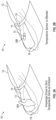
- FIG. 1 is a side perspective view of an existing heater failure detection system 10 for an aircraft heater 14 associated with an aircraft component 12. As shown in FIG. 1 , a temperature sensor 13 is attached to or embedded in the heater 14.
- a controller is configured to monitor the temperature sensor 13 and the amperage through the power leads 16. Because the amperage will vary with conditions outside the aircraft, the amperage cannot be used to detect small damage of heater 14.
- FIGS. 2A and 2B show side perspective views of the existing heater failure detection system 10 of FIG. 1 .
- the temperature sensor 13 of system 10 can detect the damaged areas 18 as specifically illustrated in FIGS. 2A and 2B .
- the amperage drops to zero and the temperature is the same as ambient.
- the temperature sensor 13 is affected, and the system 10 can detect damaged area 18B.
- the damaged area 18C may not be detectable by the existing system 10 because the rest of the heater 14 can be mostly unaffected by the damage 18C, so the amperage through the heater 14 and the temperature sensor 13 will be near normal.
- this area 18C is large enough for ice to form and then potentially break off and damage downstream parts of the aircraft such as the engine or empennage. Additionally, the ice formed on area 18C will increase drag on the aircraft and decrease lift if this is a wing.
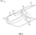
- FIG. 4 is a side perspective view of an example heater failure detection assembly 100, according to the present disclosure.
- example heater failure detection assembly/system 100 is a detection assembly/system 100 for aircraft or the like, with the heater failure detection assembly/system 100 utilizing thermal images from camera 20 for heater failure detection purposes.
- a camera e.g., an infrared camera 20
- the thermal images from the camera 20 can be processed by a controller to determine if the heater 14 has areas with abnormal temperature.
- Each image from camera 20 can be compared to a known good image, and/or each image from the camera 20 may be thresholded to show sections of the heater 14 that are above or below operational limits.
- the example camera 20 can be placed at a location where it can image the heater 14; it is noted that multiple cameras 20 can be used if a single camera 20 is impractical.
- a single camera or array of cameras may be used to monitor multiple heaters.
- at least one camera 20 can be placed on a bulkhead or spar behind a protected surface, in example embodiments.
- one or more infrared cameras 20 can monitor most or substantially all areas of the heater 14 to ensure the heater 20 operates properly.
- a temperature sensor 113 can be used to provide precise feedback for the controller, discussed below.
- the emissivity of the back of the heater 14 should be controlled so that the camera 20 can read an accurate image. It is noted that thermally reflective materials (e.g., aluminum) should not be used.
- thermochromic coating can be placed on the surface of heater 14 that is facing camera 20 to accentuate differences in temperature.
- FIGS. 5A-5C depict example infrared images from the example heater failure detection assembly 100 of the present disclosure. As shown in FIG. 5A , this image depicts an undamaged heater 14. As shown in FIG. 5B , this image depicts a slightly damaged heater 14 having small damaged area 18D. As shown in FIG. 5C , this image depicts a damaged heater 14 having larger damaged area 18D.
- FIG. 6 depicts a schematic of part of the basic logic of a controller of system 100 involving a camera of the present disclosure.
- step 201 the controller turns the power, at least one camera 20, and/or sensor 113 of assembly 100 in a particular zone to the on position.
- step 202 if the measured amperage of the heater 14 is in an acceptable range, then there is a slight delay at step 203 to allow the heater to warm up.
- step 202 if the measured amperage of the heater 14 is not in an acceptable range, then the process skips to step 206, discussed further below.
- the system 100 determines if the temperature sensor 113 is within an acceptable range. If yes, the process proceeds to step 205. At step 205, if the camera 20 shows an even temperature distribution, then the process stops as shown in FIG. 6 .
- step 206 If the camera 20 does not show an even temperature distribution at step 205, then the process continues to step 206.
- the system 100 determines if the damage detected is within acceptable limits.
- the damage is typically determined by the amount of area of the heater that is not within the correct temperature range. If yes, the system 100 at step 207 can warn a user of degraded performance of heater 14.
- step 208 the system 100 registers an error of system 100, and the heater 14 is shut down and prevented from being used again until the system is repaired.
- the example thermal camera is more manufacturable than adding a grid of traditional temperature sensors with individual wires to each sensor; and/or the solution of the present disclosure is also more manufacturable than fiber optic sensors because the fiber optic is easy to damage during manufacturing, especially when thermoplastic composite stamping is performed.
- ranges disclosed herein are inclusive of the endpoints, and the endpoints are independently combinable with each other (e.g., ranges of "up to 25 wt.%, or, more specifically, 5 wt.% to 20 wt.%", is inclusive of the endpoints and all intermediate values of the ranges of "5 wt.% to 25 wt.%,” etc.).
- “Combinations” is inclusive of blends, mixtures, alloys, reaction products, and the like.
- the terms “first,” “second,” and the like, do not denote any order, quantity, or importance, but rather are used to distinguish one element from another.
Landscapes
- Engineering & Computer Science (AREA)
- General Physics & Mathematics (AREA)
- Physics & Mathematics (AREA)
- Aviation & Aerospace Engineering (AREA)
- Theoretical Computer Science (AREA)
- Quality & Reliability (AREA)
- Computer Vision & Pattern Recognition (AREA)
- Health & Medical Sciences (AREA)
- Toxicology (AREA)
- Multimedia (AREA)
- Signal Processing (AREA)
- Spectroscopy & Molecular Physics (AREA)
- Chemical & Material Sciences (AREA)
- Life Sciences & Earth Sciences (AREA)
- Analytical Chemistry (AREA)
- Biochemistry (AREA)
- General Health & Medical Sciences (AREA)
- Immunology (AREA)
- Pathology (AREA)
- Manufacturing & Machinery (AREA)
- Transportation (AREA)
- Radiation Pyrometers (AREA)
Abstract
Description
- The present disclosure relates to heater failure detection assemblies/systems and related methods of fabrication and use and, more particularly, to heater failure detection assemblies/systems for aircraft or the like, with the heater failure detection assemblies/systems utilizing thermal images to detect the operation or failure of an aircraft heater.
- In general, heaters are used for thermal management of many aircraft parts including ice protection. Most heater assemblies include temperature sensors that can detect the failure of a section of heater. However, many damage-tolerant heaters can suffer local failure in an area of the section that is not near the temperature sensor. Therefore, the local failure can remain undetected by the controller. Adding many different sensors can be a cost and/or manufacturing challenge.
- The present disclosure provides for heater failure detection assemblies/systems and related methods of fabrication and use. More particularly, the present disclosure provides for heater failure detection assemblies/systems for aircraft or the like, with the heater failure detection assemblies/systems utilizing thermal images to detect the operation or failure of an aircraft heater.
- According to an aspect, there is provided a heater failure detection assembly including at least one camera positioned with respect to a heater of an aircraft component, the at least one camera configured to image and detect abnormal temperature areas of the heater; and wherein images of the abnormal temperature areas from the camera are configured to be compared to a known acceptable image or are configured to be thresholded to show sections of the heater that are above or below pre-determined operational limits to detect the operation or failure of the heater.
- In addition to one or more of the features described, or as an alternative to any of the foregoing embodiments, the camera is an infrared camera or a thermal imaging camera, and wherein the heater is an ice protection heater of an aircraft.
- In addition to one or more of the features described, or as an alternative to any of the foregoing embodiments, the aircraft component is an engine inlet, a wing or a stabilizer.
- In addition to one or more of the features described, or as an alternative to any of the foregoing embodiments, further including a plurality of heaters, the at least one camera positioned with respect to the plurality of heaters of the aircraft component, the at least one camera configured to image and detect abnormal temperature areas of the plurality of heaters.
- In addition to one or more of the features described, or as an alternative to any of the foregoing embodiments, wherein the at least one camera is positioned or mounted on a bulkhead or spar behind a protected surface.
- In addition to one or more of the features described, or as an alternative to any of the foregoing embodiments, further including a controller, the controller configured to determine if the heater has abnormal temperature areas.
- In addition to one or more of the features described, or as an alternative to any of the foregoing embodiments, further including a plurality of cameras positioned with respect to the heater, the plurality of cameras configured to image and detect abnormal temperature areas of the heater.
- In addition to one or more of the features described, or as an alternative to any of the foregoing embodiments, further including a controller in communication with the heater failure detection assembly.
- In addition to one or more of the features described, or as an alternative to any of the foregoing embodiments, further including a temperature sensor in communication with the heater.
- In addition to one or more of the features described, or as an alternative to any of the foregoing embodiments, further including a thermochromic coating associated with the heater to accentuate differences in temperature.
- According to an aspect, there is provided a method for detecting heater failure including positioning at least one camera with respect to a heater of an aircraft component; and imaging and detecting abnormal temperature areas of the heater via the at least one camera; and comparing the images of the abnormal temperature areas to a known acceptable image or thresholding the images of the abnormal temperature areas to show sections of the heater that are above or below pre-determined operational limits to detect the operation or failure of the heater.
- In addition to one or more of the features described, or as an alternative to any of the foregoing embodiments, the camera is an infrared camera or a thermal imaging camera, and wherein the heater is an ice protection heater of an aircraft.
- In addition to one or more of the features described, or as an alternative to any of the foregoing embodiments, the aircraft component is an engine inlet, a wing or a stabilizer.
- In addition to one or more of the features described, or as an alternative to any of the foregoing embodiments, further comprising a plurality of heaters, the at least one camera positioned with respect to the plurality of heaters of the aircraft component, the at least one camera configured to image and detect abnormal temperature areas of the plurality of heaters.
- In addition to one or more of the features described, or as an alternative to any of the foregoing embodiments, wherein the at least one camera is positioned or mounted on a bulkhead or spar behind a protected surface.
- In addition to one or more of the features described, or as an alternative to any of the foregoing embodiments, further including a controller, the controller configured to determine if the heater has abnormal temperature areas.
- In addition to one or more of the features described, or as an alternative to any of the foregoing embodiments, further including a plurality of cameras positioned with respect to the heater, the plurality of cameras configured to image and detect abnormal temperature areas of the heater.
- In addition to one or more of the features described, or as an alternative to any of the foregoing embodiments, further including a controller in communication with the heater failure detection assembly.
- In addition to one or more of the features described, or as an alternative to any of the foregoing embodiments, further including a temperature sensor in communication with the heater.
- In addition to one or more of the features described, or as an alternative to any of the foregoing embodiments, further including a thermochromic coating associated with the heater to accentuate differences in temperature.
- The above described and other features are exemplified by the following figures and detailed description.
- Any combination or permutation of embodiments is envisioned. Additional features, functions and applications of the disclosed systems, assemblies and methods of the present disclosure will be apparent from the description which follows, particularly when read in conjunction with the appended figures. All references listed in this disclosure are hereby incorporated by reference in their entireties.
- The following figures are example embodiments wherein the like elements are numbered alike.
- Features and aspects of embodiments are described below with reference to the accompanying drawings, in which elements are not necessarily depicted to scale.
- Example embodiments of the present disclosure are further described with reference to the appended figures. It is to be noted that the various features, steps, and combinations of features/steps described below and illustrated in the figures can be arranged and organized differently to result in embodiments which are still within the scope of the present disclosure. To assist those of ordinary skill in the art in making and using the disclosed systems, assemblies and methods, reference is made to the appended figures, wherein:
-
FIG. 1 is a side perspective view of an existing heater failure detection system for an aircraft heater; -
FIGS. 2A and 2B show side perspective views of the existing heater failure detection system ofFIG. 1 ; -
FIG. 3 shows another side perspective view of the existing heater failure detection system ofFIG. 1 ; -
FIG. 4 is a side perspective view of an example heater failure detection assembly, according to the present disclosure; -
FIGS. 5A-5C depict example infrared images from the example heater failure detection assembly, according to the present disclosure; and -
FIG. 6 is a schematic showing the basic logic of a controller associated with the example heater failure detection assembly, according to the present disclosure. - The example embodiments disclosed herein are illustrative of heater failure detection assemblies for aircraft, and systems of the present disclosure and methods/techniques thereof. It should be understood, however, that the disclosed embodiments are merely examples of the present disclosure, which may be embodied in various forms. Therefore, details disclosed herein with reference to example heater failure detection assemblies and associated processes/techniques of fabrication/assembly and use are not to be interpreted as limiting, but merely as the basis for teaching one skilled in the art how to make and use the systems/assemblies and/or alternative systems/assemblies of the present disclosure.
- The present disclosure provides for heater failure detection assemblies/systems and related methods of fabrication and use. More particularly, the present disclosure provides for heater failure detection assemblies/systems for aircraft or the like, with the heater failure detection assemblies/systems utilizing thermal images to detect the operation or failure of an aircraft heater.
-
FIG. 1 is a side perspective view of an existing heaterfailure detection system 10 for anaircraft heater 14 associated with anaircraft component 12. As shown inFIG. 1 , atemperature sensor 13 is attached to or embedded in theheater 14. - A controller is configured to monitor the
temperature sensor 13 and the amperage through the power leads 16. Because the amperage will vary with conditions outside the aircraft, the amperage cannot be used to detect small damage ofheater 14. -
FIGS. 2A and 2B show side perspective views of the existing heaterfailure detection system 10 ofFIG. 1 . As shown inFIG. 2A and 2B , thetemperature sensor 13 ofsystem 10 can detect the damaged areas 18 as specifically illustrated inFIGS. 2A and 2B . For example and as shown inFIG. 2A , with this particular damaged area 18, the amperage drops to zero and the temperature is the same as ambient. As shown inFIG. 2B , thetemperature sensor 13 is affected, and thesystem 10 can detect damagedarea 18B. - As shown in
FIG. 3 , the damagedarea 18C may not be detectable by the existingsystem 10 because the rest of theheater 14 can be mostly unaffected by thedamage 18C, so the amperage through theheater 14 and thetemperature sensor 13 will be near normal. - In
FIG. 3 , thisarea 18C is large enough for ice to form and then potentially break off and damage downstream parts of the aircraft such as the engine or empennage. Additionally, the ice formed onarea 18C will increase drag on the aircraft and decrease lift if this is a wing. -
FIG. 4 is a side perspective view of an example heaterfailure detection assembly 100, according to the present disclosure. - In general and as discussed further below, example heater failure detection assembly/
system 100 is a detection assembly/system 100 for aircraft or the like, with the heater failure detection assembly/system 100 utilizing thermal images fromcamera 20 for heater failure detection purposes. - As shown in
FIG. 4 , a camera (e.g., an infrared camera 20) can be placed at a location where it can image the heater 14 (or a plurality of heaters 14). During operation, the thermal images from thecamera 20 can be processed by a controller to determine if theheater 14 has areas with abnormal temperature. Each image fromcamera 20 can be compared to a known good image, and/or each image from thecamera 20 may be thresholded to show sections of theheater 14 that are above or below operational limits. Theexample camera 20 can be placed at a location where it can image theheater 14; it is noted thatmultiple cameras 20 can be used if asingle camera 20 is impractical. A single camera or array of cameras may be used to monitor multiple heaters. For ice protection applications such as engine inlets, wings, and stabilizers (e.g., aircraft components 12), at least onecamera 20 can be placed on a bulkhead or spar behind a protected surface, in example embodiments. - As such and as shown in
FIG. 4 , in particularly sensitive areas of the aircraft, one or moreinfrared cameras 20 can monitor most or substantially all areas of theheater 14 to ensure theheater 20 operates properly. - With
assembly 100, atemperature sensor 113 can be used to provide precise feedback for the controller, discussed below. - In example embodiments and with
assembly 100, the emissivity of the back of theheater 14 should be controlled so that thecamera 20 can read an accurate image. It is noted that thermally reflective materials (e.g., aluminum) should not be used. - It is noted that a thermochromic coating can be placed on the surface of
heater 14 that is facingcamera 20 to accentuate differences in temperature. -
FIGS. 5A-5C depict example infrared images from the example heaterfailure detection assembly 100 of the present disclosure. As shown inFIG. 5A , this image depicts anundamaged heater 14. As shown inFIG. 5B , this image depicts a slightly damagedheater 14 having small damagedarea 18D. As shown inFIG. 5C , this image depicts a damagedheater 14 having larger damagedarea 18D. -
FIG. 6 depicts a schematic of part of the basic logic of a controller ofsystem 100 involving a camera of the present disclosure. - As shown in
FIG. 6 , instep 201, the controller turns the power, at least onecamera 20, and/orsensor 113 ofassembly 100 in a particular zone to the on position. Instep 202, if the measured amperage of theheater 14 is in an acceptable range, then there is a slight delay atstep 203 to allow the heater to warm up. Atstep 202, if the measured amperage of theheater 14 is not in an acceptable range, then the process skips to step 206, discussed further below. - After the delay at
step 203, thesystem 100 determines if thetemperature sensor 113 is within an acceptable range. If yes, the process proceeds to step 205. Atstep 205, if thecamera 20 shows an even temperature distribution, then the process stops as shown inFIG. 6 . - If the
camera 20 does not show an even temperature distribution atstep 205, then the process continues to step 206. - At
step 206, thesystem 100 determines if the damage detected is within acceptable limits. The damage is typically determined by the amount of area of the heater that is not within the correct temperature range. If yes, thesystem 100 atstep 207 can warn a user of degraded performance ofheater 14. - If no at
step 206, then atstep 208 thesystem 100 registers an error ofsystem 100, and theheater 14 is shut down and prevented from being used again until the system is repaired. - There are many benefits of the assemblies, systems and methods of the present disclosure, including, without limitation, the example thermal camera is more manufacturable than adding a grid of traditional temperature sensors with individual wires to each sensor; and/or the solution of the present disclosure is also more manufacturable than fiber optic sensors because the fiber optic is easy to damage during manufacturing, especially when thermoplastic composite stamping is performed.
- While particular embodiments have been described, alternatives, modifications, variations, improvements, and substantial equivalents that are or may be presently unforeseen may arise to applicants or others skilled in the art. Accordingly, the appended claims as filed and as they may be amended are intended to embrace all such alternatives, modifications variations, improvements, and substantial equivalents.
- The ranges disclosed herein are inclusive of the endpoints, and the endpoints are independently combinable with each other (e.g., ranges of "up to 25 wt.%, or, more specifically, 5 wt.% to 20 wt.%", is inclusive of the endpoints and all intermediate values of the ranges of "5 wt.% to 25 wt.%," etc.). "Combinations" is inclusive of blends, mixtures, alloys, reaction products, and the like. The terms "first," "second," and the like, do not denote any order, quantity, or importance, but rather are used to distinguish one element from another. The terms "a" and "an" and "the" do not denote a limitation of quantity and are to be construed to cover both the singular and the plural, unless otherwise indicated herein or clearly contradicted by context. "Or" means "and/or" unless clearly stated otherwise. Reference throughout the specification to "some embodiments", "an embodiment", and so forth, means that a particular element described in connection with the embodiment is included in at least one embodiment described herein, and may or may not be present in other embodiments. In addition, it is to be understood that the described elements may be combined in any suitable manner in the various embodiments. A "combination thereof' is open and includes any combination comprising at least one of the listed components or properties optionally together with a like or equivalent component or property not listed.
- Unless defined otherwise, technical and scientific terms used herein have the same meaning as is commonly understood by one of skill in the art to which this application belongs. All cited patents, patent applications, and other references are incorporated herein by reference in their entirety. However, if a term in the present application contradicts or conflicts with a term in the incorporated reference, the term from the present application takes precedence over the conflicting term from the incorporated reference.
- Although the assemblies, systems and methods of the present disclosure have been described with reference to example embodiments thereof, the present disclosure is not limited to such example embodiments and/or implementations. Rather, the assemblies, systems and methods of the present disclosure are susceptible to many implementations and applications, as will be readily apparent to persons skilled in the art from the disclosure hereof. The present disclosure expressly encompasses such modifications, enhancements and/or variations of the disclosed embodiments. Since many changes could be made in the above construction and many widely different embodiments of this disclosure could be made without departing from the scope thereof, it is intended that all matter contained in the drawings and specification shall be interpreted as illustrative and not in a limiting sense. Additional modifications, changes, and substitutions are intended in the foregoing disclosure. Accordingly, it is appropriate that the appended claims be construed broadly and in a manner consistent with the scope of the disclosure.
Claims (15)
- A heater failure detection assembly comprising:at least one camera positioned with respect to a heater of an aircraft component, the at least one camera configured to image and detect abnormal temperature areas of the heater; andwherein images of the abnormal temperature areas from the camera are configured to be compared to a known acceptable image or are configured to be thresholded to show sections of the heater that are above or below pre-determined operational limits to detect the operation or failure of the heater.
- The assembly of claim 1, wherein the camera is an infrared camera or a thermal imaging camera; and wherein the heater is an ice protection heater of an aircraft.
- The assembly of claim 1 or 2, wherein the aircraft component is an engine inlet, a wing or a stabilizer.
- The assembly of claim 1, 2 or 3 further comprising a plurality of heaters, the at least one camera positioned with respect to the plurality of heaters of the aircraft component, the at least one camera configured to image and detect abnormal temperature areas of the plurality of heaters.
- The assembly of any preceding claim, wherein the at least one camera is positioned or mounted on a bulkhead or spar behind a protected surface.
- The assembly of any preceding claim further comprising a controller, the controller configured to determine if the heater has abnormal temperature areas.
- The assembly of any preceding claim further comprising a plurality of cameras positioned with respect to the heater, the plurality of cameras configured to image and detect abnormal temperature areas of the heater.
- The assembly of any preceding claim further comprising a controller in communication with the heater failure detection assembly.
- The assembly of any preceding claim further comprising a temperature sensor in communication with the heater.
- The assembly of any preceding claim further comprising a thermochromic coating associated with the heater to accentuate differences in temperature.
- A method for detecting heater failure comprising:positioning at least one camera with respect to a heater of an aircraft component;imaging and detecting abnormal temperature areas of the heater via the at least one camera; andcomparing the images of the abnormal temperature areas to a known acceptable image or thresholding the images of the abnormal temperature areas to show sections of the heater that are above or below pre-determined operational limits to detect the operation or failure of the heater.
- The method of claim 11, wherein the camera is an infrared camera or a thermal imaging camera; and wherein the heater is an ice protection heater of an aircraft; and/or
wherein the aircraft component is an engine inlet, a wing or a stabilizer. - The method of claims 11 or 12 further comprising a plurality of heaters, the at least one camera positioned with respect to the plurality of heaters of the aircraft component, the at least one camera configured to image and detect abnormal temperature areas of the plurality of heaters; and/or
wherein the at least one camera is positioned or mounted on a bulkhead or spar behind a protected surface. - The method of claim 11, 12 or 13, further comprising a controller,
the controller configured to determine if the heater has abnormal temperature areas. - The method of any of claim 11 to 14 further comprising at least one of:a plurality of cameras positioned with respect to the heater, the plurality of cameras configured to image and detect abnormal temperature areas of the heater;a controller in communication with a heater failure detection assembly;a temperature sensor in communication with the heater; anda thermochromic coating associated with the heater to accentuate differences in temperature.
Applications Claiming Priority (1)
| Application Number | Priority Date | Filing Date | Title |
|---|---|---|---|
| US18/337,815 US12315140B2 (en) | 2023-06-20 | 2023-06-20 | System for detecting heater failure by thermal image |
Publications (1)
| Publication Number | Publication Date |
|---|---|
| EP4480823A1 true EP4480823A1 (en) | 2024-12-25 |
Family
ID=91581854
Family Applications (1)
| Application Number | Title | Priority Date | Filing Date |
|---|---|---|---|
| EP24182600.7A Pending EP4480823A1 (en) | 2023-06-20 | 2024-06-17 | System for detecting heater failure by thermal image |
Country Status (2)
| Country | Link |
|---|---|
| US (1) | US12315140B2 (en) |
| EP (1) | EP4480823A1 (en) |
Citations (5)
| Publication number | Priority date | Publication date | Assignee | Title |
|---|---|---|---|---|
| US20160279923A1 (en) * | 2011-05-05 | 2016-09-29 | The Boeing Company | Monitoring Composite Manufacturing and Repair Processes Using Chromatic Films |
| CN106017721A (en) * | 2015-03-26 | 2016-10-12 | 波音公司 | System and method for monitoring the thermal environment of a composite structure using a thermochromatic evaluation component |
| WO2018215103A1 (en) * | 2017-05-24 | 2018-11-29 | Siemens Wind Power A/S | Method of performing structural inspection of a wind turbine rotor blade |
| US20190382139A1 (en) * | 2018-06-19 | 2019-12-19 | The Boeing Company | Methods and apparatus to detect deicing heater conditions |
| WO2020054460A1 (en) * | 2018-09-10 | 2020-03-19 | 国立研究開発法人産業技術総合研究所 | Structure having an interior space, and anomaly detection system for same |
Family Cites Families (8)
| Publication number | Priority date | Publication date | Assignee | Title |
|---|---|---|---|---|
| EP0459216A3 (en) * | 1990-06-01 | 1993-03-17 | The Bfgoodrich Company | Electrical heater de-icer |
| DE10220413A1 (en) | 2002-05-08 | 2003-11-27 | Behr Gmbh & Co | Method and device for monitoring the temperature of an electric heating element |
| CN103448913A (en) | 2013-09-11 | 2013-12-18 | 中国民航大学 | Airplane deicing real-time monitoring device |
| US10184840B2 (en) * | 2015-01-07 | 2019-01-22 | The Boeing Company | Portable device for quantifying thermochromatic coating signatures |
| GB2564611A (en) * | 2016-04-15 | 2019-01-16 | Walmart Apollo Llc | Systems and methods for thermal monitoring in a retail facility |
| FR3083044A1 (en) | 2018-06-21 | 2019-12-27 | Valeo Systemes Thermiques | METHOD FOR REGULATING THE TEMPERATURE OF A HEATING SURFACE OF A RADIANT PANEL AND CORRESPONDING REGULATING DEVICE. |
| EP3898029B1 (en) * | 2018-12-18 | 2025-05-21 | Marposs Societa' Per Azioni | Thermographic check of a mold in a foundry |
| GB2594915B (en) * | 2020-03-16 | 2022-10-26 | Ultra Electronics Ltd | Detecting delamination in a laminated structure |
-
2023
- 2023-06-20 US US18/337,815 patent/US12315140B2/en active Active
-
2024
- 2024-06-17 EP EP24182600.7A patent/EP4480823A1/en active Pending
Patent Citations (5)
| Publication number | Priority date | Publication date | Assignee | Title |
|---|---|---|---|---|
| US20160279923A1 (en) * | 2011-05-05 | 2016-09-29 | The Boeing Company | Monitoring Composite Manufacturing and Repair Processes Using Chromatic Films |
| CN106017721A (en) * | 2015-03-26 | 2016-10-12 | 波音公司 | System and method for monitoring the thermal environment of a composite structure using a thermochromatic evaluation component |
| WO2018215103A1 (en) * | 2017-05-24 | 2018-11-29 | Siemens Wind Power A/S | Method of performing structural inspection of a wind turbine rotor blade |
| US20190382139A1 (en) * | 2018-06-19 | 2019-12-19 | The Boeing Company | Methods and apparatus to detect deicing heater conditions |
| WO2020054460A1 (en) * | 2018-09-10 | 2020-03-19 | 国立研究開発法人産業技術総合研究所 | Structure having an interior space, and anomaly detection system for same |
Also Published As
| Publication number | Publication date |
|---|---|
| US12315140B2 (en) | 2025-05-27 |
| US20240428398A1 (en) | 2024-12-26 |
Similar Documents
| Publication | Publication Date | Title |
|---|---|---|
| EP2700925B1 (en) | Total Air Temperature Probes for Reducing Deicing Heater Error | |
| US11167861B2 (en) | Blockage preventing and heated air data probe | |
| US10018580B2 (en) | Apparatus and method for detecting water or ice | |
| RU2534493C2 (en) | System and method for icing sensor application | |
| US8864370B2 (en) | Ice breaking probe for measuring global air temperature | |
| US9666051B2 (en) | Method and a device for detecting icing at an air inlet of a turboshaft engine | |
| EP3012191B1 (en) | Method for determining a state of a component in a high lift system of an aircraft, high lift system of an aircraft and aircraft having such a high lift system | |
| US20090306928A1 (en) | Method and system for detecting the risk of icing on aerodynamic surfaces | |
| US9429482B2 (en) | Total air temperature probe with low frontal projected area | |
| CN102052979A (en) | Total air temperature probe and method for reducing de-icing/anti-icing heater error | |
| JP6663369B2 (en) | Wind turbine blade damage detection method and wind turbine | |
| US11993371B2 (en) | Thermal relief doors for overheat prevention of anti-ice systems on aircraft | |
| US20240428398A1 (en) | System for detecting heater failure by thermal image | |
| JP2012140938A5 (en) | ||
| WO2016054004A1 (en) | Online sensor calibration verification system | |
| US20140191083A1 (en) | Ice protection system | |
| US8602361B2 (en) | Laminar flow monitor | |
| US20190212435A1 (en) | Method and Assembly for Monitoring a Hot Gas Region of a Gas Turbine | |
| US8541720B2 (en) | Apparatus for remotely measuring surface temperature using embedded components | |
| EP3282236A1 (en) | Pressure sensor temperature coefficient of offset adjustment | |
| WO2018215103A1 (en) | Method of performing structural inspection of a wind turbine rotor blade | |
| JP4854020B2 (en) | Heat exchanger abnormality detection device and heat exchanger abnormality detection method | |
| KR102051098B1 (en) | Active heater control device for Flush port Air Data System anti-icing | |
| CN114207279A (en) | Estimation of rotor operating characteristics of a wind turbine | |
| EP3282337B2 (en) | Heat exchanger system and method for detecting a relocation of a temperature sensor in a heat exchanger system |
Legal Events
| Date | Code | Title | Description |
|---|---|---|---|
| PUAI | Public reference made under article 153(3) epc to a published international application that has entered the european phase |
Free format text: ORIGINAL CODE: 0009012 |
|
| STAA | Information on the status of an ep patent application or granted ep patent |
Free format text: STATUS: THE APPLICATION HAS BEEN PUBLISHED |
|
| AK | Designated contracting states |
Kind code of ref document: A1 Designated state(s): AL AT BE BG CH CY CZ DE DK EE ES FI FR GB GR HR HU IE IS IT LI LT LU LV MC ME MK MT NL NO PL PT RO RS SE SI SK SM TR |
|
| STAA | Information on the status of an ep patent application or granted ep patent |
Free format text: STATUS: REQUEST FOR EXAMINATION WAS MADE |
|
| 17P | Request for examination filed |
Effective date: 20250625 |
|
| STAA | Information on the status of an ep patent application or granted ep patent |
Free format text: STATUS: EXAMINATION IS IN PROGRESS |
|
| 17Q | First examination report despatched |
Effective date: 20260102 |