EP4480819A1 - High pressure water supply system and aircraft equipped with such system - Google Patents
High pressure water supply system and aircraft equipped with such system Download PDFInfo
- Publication number
- EP4480819A1 EP4480819A1 EP23181043.3A EP23181043A EP4480819A1 EP 4480819 A1 EP4480819 A1 EP 4480819A1 EP 23181043 A EP23181043 A EP 23181043A EP 4480819 A1 EP4480819 A1 EP 4480819A1
- Authority
- EP
- European Patent Office
- Prior art keywords
- water
- water supply
- pressurisation
- consumers
- pressure
- Prior art date
- Legal status (The legal status is an assumption and is not a legal conclusion. Google has not performed a legal analysis and makes no representation as to the accuracy of the status listed.)
- Pending
Links
Images


Classifications
-
- E—FIXED CONSTRUCTIONS
- E03—WATER SUPPLY; SEWERAGE
- E03B—INSTALLATIONS OR METHODS FOR OBTAINING, COLLECTING, OR DISTRIBUTING WATER
- E03B7/00—Water main or service pipe systems
- E03B7/07—Arrangement of devices, e.g. filters, flow controls, measuring devices, siphons or valves, in the pipe systems
- E03B7/075—Arrangement of devices for control of pressure or flow rate
-
- B—PERFORMING OPERATIONS; TRANSPORTING
- B64—AIRCRAFT; AVIATION; COSMONAUTICS
- B64D—EQUIPMENT FOR FITTING IN OR TO AIRCRAFT; FLIGHT SUITS; PARACHUTES; ARRANGEMENT OR MOUNTING OF POWER PLANTS OR PROPULSION TRANSMISSIONS IN AIRCRAFT
- B64D11/00—Passenger or crew accommodation; Flight-deck installations not otherwise provided for
- B64D11/04—Galleys
-
- E—FIXED CONSTRUCTIONS
- E03—WATER SUPPLY; SEWERAGE
- E03B—INSTALLATIONS OR METHODS FOR OBTAINING, COLLECTING, OR DISTRIBUTING WATER
- E03B5/00—Use of pumping plants or installations; Layouts thereof
-
- E—FIXED CONSTRUCTIONS
- E03—WATER SUPPLY; SEWERAGE
- E03B—INSTALLATIONS OR METHODS FOR OBTAINING, COLLECTING, OR DISTRIBUTING WATER
- E03B7/00—Water main or service pipe systems
- E03B7/04—Domestic or like local pipe systems
-
- G—PHYSICS
- G05—CONTROLLING; REGULATING
- G05B—CONTROL OR REGULATING SYSTEMS IN GENERAL; FUNCTIONAL ELEMENTS OF SUCH SYSTEMS; MONITORING OR TESTING ARRANGEMENTS FOR SUCH SYSTEMS OR ELEMENTS
- G05B19/00—Program-control systems
- G05B19/02—Program-control systems electric
- G05B19/04—Program control other than numerical control, i.e. in sequence controllers or logic controllers
- G05B19/042—Program control other than numerical control, i.e. in sequence controllers or logic controllers using digital processors
-
- B—PERFORMING OPERATIONS; TRANSPORTING
- B64—AIRCRAFT; AVIATION; COSMONAUTICS
- B64D—EQUIPMENT FOR FITTING IN OR TO AIRCRAFT; FLIGHT SUITS; PARACHUTES; ARRANGEMENT OR MOUNTING OF POWER PLANTS OR PROPULSION TRANSMISSIONS IN AIRCRAFT
- B64D11/00—Passenger or crew accommodation; Flight-deck installations not otherwise provided for
- B64D11/02—Toilet fittings
-
- G—PHYSICS
- G05—CONTROLLING; REGULATING
- G05B—CONTROL OR REGULATING SYSTEMS IN GENERAL; FUNCTIONAL ELEMENTS OF SUCH SYSTEMS; MONITORING OR TESTING ARRANGEMENTS FOR SUCH SYSTEMS OR ELEMENTS
- G05B2219/00—Program-control systems
- G05B2219/30—Nc systems
- G05B2219/45—Nc applications
- G05B2219/45071—Aircraft, airplane, ship cleaning manipulator, paint stripping
Definitions
- the present disclosure generally relates to a high pressure water supply system for an aircraft and an aircraft having such water supply system.
- the present disclosure relates to a water supply system comprising a plurality of pressurisation units, each conveying water to one more of a plurality of water consumers, wherein an output pressure of the pressurisation units is controlled based on a hydraulic resistance of a high pressure water supply line between the respective pressurisation unit and the water consumer.
- the present disclosure relates to an aircraft comprising such water supply system.
- a conventional water supply system for aircrafts includes a central water tank and a water conveying device supplying water to all water consumers in the aircraft.
- water consumers include lavatory monuments (e.g. having a faucet and a toilet) and galleys (e.g. having a faucet, a hot water dispenser, food preparation devices, etc.).
- the water conveying device is designed to provide a sufficient amount of water to all water consumers (sufficient water flow rate), and to provide the necessary overall water pressure for the entire system.
- a rinsing nozzle for a toilet usually requires a higher water pressure than a faucet.
- a monument further away from the central water conveying device requires a higher water pressure due to the pressure loss in the water supply duct.
- the central water conveying device hence, is designed for a maximum water pressure depending on the highest pressure demand, and pressure reducers are installed at water consumers that do not require the maximum water pressure.
- a high pressure water supply system for an aircraft comprises a main water supply tank, a plurality of water consumers, a plurality of pressurisation units configured to convey water from the main water supply tank to the plurality of water consumers, and a control unit.
- the water supply system particularly, includes one pressurisation unit of the plurality of pressurisation units that conveys water to a first subset of water consumers of the plurality of water consumers via a corresponding high pressure water supply line.
- the control unit is configured to control an output pressure of said one pressurisation unit depending on a hydraulic resistance of the high pressure water supply line.
- the hydraulic resistance is based on a length, inner diameter, inner surface roughness, and number and types of bends of the high pressure water supply line, as well as a difference in height between pressurisation unit and water consumers and flow rate currently used.
- control unit can be configured to control the pressurisation unit in accordance with the hydraulic resistance specific for one of these activated water consumers. This may require that other water consumers, such as sensible water consumers or water consumers requiring a rather low-pressure, can be equipped with a throttling device or pressure reducer.
- water consumers connected to a rather short supply line or of rather low hydraulic resistance may also be equipped with a throttling device or pressure reducer, also referred to as an (adjustable) restrictor as a mere example, a proportional valve could be employed and/or other active restrictors, so that a dynamic adjustment of the water pressure at each individual water consumer can be provided.
- a throttling device or pressure reducer also referred to as an (adjustable) restrictor
- a proportional valve could be employed and/or other active restrictors, so that a dynamic adjustment of the water pressure at each individual water consumer can be provided. This allows a hydraulic balancing of all water consumers, while achieving an optimised pressurisation unit operation.
- a pressurisation unit of the plurality of pressurisation units can be a pump, a positive displacement pump (such as a gear pump, membrane pump, piston pump, impeller pump), a centrifugal pump (such as an impeller pump or a site channel pump), a compressor, a micro-pump, or any other fluid conveying device.
- a positive displacement pump such as a gear pump, membrane pump, piston pump, impeller pump
- a centrifugal pump such as an impeller pump or a site channel pump
- a compressor a micro-pump, or any other fluid conveying device.
- each of the plurality of water consumers can be supplied with high pressure water from a respective one of the plurality of pressurisation units via a respective high pressure water supply line.
- the number of pressurisation units is equal to the number of water consumers. This allows installing small pressurisation units, such as micro-pumps, since only a small amount of water has to be conveyed at a predefined pressure.
- any variable control of a flow rate or pressure of the pressurisation unit can be omitted, since such parameters can be preset.
- the first subset of water consumers can comprise two or more water consumers of the plurality of water consumers.
- the two or more water consumers may form a group of water consumers that are similar or have a particular characteristic in common, such as water consumers in the same monument, and/or water consumers in different monuments in a region of the aircraft requiring a water supply line of substantially same hydraulic resistance, and/or the same type of water consumers in a region of the aircraft requiring a water supply line of substantially same hydraulic resistance.
- the same type of water consumers in the first subset can be all faucets that are spatially close to one another, such as faucets of adjacent lavatories and/or galleys.
- pressurisation unit for the particular first subset of water consumers that can be operated in the same manner for each of the water consumers, which simplifies control of the pressurisation unit or allows omitting any control, but preset parameters of the pressurisation unit. For instance, if one pressurisation unit supplies water to a small number of faucets or other water consumers of same type, the pressurisation unit can be operated with the same parameters or characteristics independent of which water consumer is currently running.
- control unit is further configured to control an output pressure of the pressurisation unit associated with this subset or group depending on the number of concurrently running water consumers. Nevertheless, a main factor for the required output pressure is the hydraulic resistance of the associated water supply line running from the pressurisation unit to the subset or group of water consumers.
- the water supply system can further comprise a second subset of water consumers of the plurality of water consumers, the second subset comprising one or more water consumers.
- the plurality of water consumers is divided into a first and second subset. It is to be understood that the number of subsets is not restricted to two, but that the present disclosure covers any number of subsets.
- Each subset can be supplied with water from a respective pressurisation unit of the plurality of pressurisation units.
- control unit can be further configured to control an output pressure of each of the plurality of pressurisation units depending on a hydraulic resistance of the respective high pressure water supply line.
- control unit can be further configured to control the output pressure of one or more of the plurality of pressurisation units depending on a type of water consumer that is currently activated, i.e. that needs a water supply, a number of water consumers being currently activated, i.e. that need a water supply simultaneously, or other characteristics of the water consumers.
- another pressurisation unit of the plurality of pressurisation units can convey water to the first subset of water consumers via the corresponding high pressure water supply line.
- the other pressurisation unit can be employed to increase a flow rate and/or output pressure in the high-pressure water supply line to the first subset of water consumers.
- the other pressurisation unit can be fluidly connected to the one pressurisation unit in parallel or in series. This allows an increase of flow rate and pressure, respectively.
- pressurisation units can be connected to one another in parallel and/or in series or combinations thereof, in order to achieve a desired flow rate and/or output pressure.
- control unit can be further configured to control the one pressurisation unit and the other pressurisation unit depending on a required flow rate of water at the first subset of water consumers.
- control unit can be further configured to control the one pressurisation unit depending on a required water pressure at the first subset of water consumers. For instance, if two water consumers request water at the same time, the flow rate may be increased. Likewise, if a water consumer that requires a higher pressure than other water consumers (of the same subset) requests a water demand, a higher pressure of the water supply can be provided via the multiple pressurisation units.
- a rinsing nozzle of a toilet requires a higher pressure than a faucet installed in the same monument. This higher pressure can be achieved by controlling the other pressurisation unit to operate only in case the rinsing nozzle is activated.
- the water supply system can further comprise a pressure sensor in the high pressure water supply line.
- the control unit can then be further configured to maintain the output pressure of said one pressurisation unit at a predefined pressure level. This allows pressurizing the high pressure water supply line at the predefined pressure level, so that any time water is required at an associated water consumer the water has the predefined pressure level. This allows omission of any control devices at the water consumers, which control devices would otherwise send information to the control unit. Thus, all control components can be located at the pressurisation unit, which simplifies the overall system.
- the water supply system can further comprise a pressure equalising reservoir fluidly connected to the high pressure water supply line and configured to mechanically maintain the predefined pressure level in the high pressure water supply line.
- the reservoir can be any compressible or elastic element, including an elastic hose section, or any container, in which a water pressure can be built up and can be released into the high pressure water supply line, for example, until the pressurisation unit begins operating or increases its output pressure.
- the mechanically maintaining of the predefined pressure level can be achieved by an elastic or biased element, such as a membrane or a spring-loaded piston.
- At least one of the plurality of water consumers can comprise a micro storage device fluidly connected to the high pressure water supply line, configured to store an amount of water required for flushing a toilet and to achieve a water pressure sufficient for a nozzle rinsing/flushing the toilet.
- the micro storage device can include a mechanical water conveying means, such as an elastic element, for example, a spring-loaded piston, a membrane or other biased element.
- water from the high pressure water supply line may be filled into the micro storage device, e.g., an amount sufficient for flushing the toilet.
- the mechanical water conveying means presses the water to the nozzle for rinsing/flushing the toilet.
- a fluid connection to the high pressure water supply line may be open or closed, so that the flushing of the toilet is achieved under support of the water supply from the high-pressure water supply line or solely by the mechanical water conveying means.
- Such micro storage device allows operating the pressurisation unit associated with the toilet with a particular flow rate that may not be high enough for operating the nozzle for rinsing the toilet, but is preset in view of a flow rate required for a faucet also associated with the pressurisation unit.
- the pressurisation unit is preset in view of the faucet (e.g., requiring a larger amount of water at a lower pressure), while the micro storage device achieves flushing the toilet in a fast manner, but requiring a small amount of water at a higher pressure (compared to the faucet).
- At least one of the plurality of water consumers can comprise an unpressurised water buffer tank and a water conveying device configured to convey water from the unpressurised water buffer tank to a faucet.
- the unpressurised water buffer tank and water conveying device may be associated with a faucet or similar water fountain device.
- the unpressurised water buffer tank is fluidly connected to the high pressure water supply line, for example, via a shutoff valve, and is vented to the ambient, so that no or only a small pressure inside the unpressurised water buffer tank can build up.
- a venting line or overflow line can be connected to the unpressurised water buffer tank for venting the tank to the ambient.
- venting or overflow line can have a larger diameter than the high pressure supply line, in order to avoid an unwanted pressure build-up in the buffer.
- a duct or pipe between the unpressurised water buffer tank, conveying device and water consumer can have a different diameter (particularly larger) as the high-pressure water supply duct.
- the one pressurisation unit can be operated in accordance with parameters and characteristics for another water consumer requiring a higher pressure, such as a nozzle for rinsing a toilet.
- the faucet Via the unpressurised water buffer tank, the faucet can be decoupled from the high-pressure water supply line (particularly with respect to the provided water pressure) in any operational state fluidly downstream of the shutoff valve for filling the unpressurised water buffer tank.
- control unit can further be configured to control the pressurisation unit associated with the unpressurised water buffer tank to control and output pressure of the pressurisation unit depending on the needs to refill the unpressurised water buffer tank.
- control unit can further be configured to control the pressurisation unit depending on whether the unpressurised water buffer tank is to be refilled and a further water consumer needs a water supply at the same time.
- At least one of the plurality of water consumers can comprise a consumer controller configured to transmit a signal indicating a water usage at the associated consumer, and the control unit can be further configured to receive the signal transmitted from the consumer controller and to control the output pressure of said one pressurisation unit based on the received signal. This allows operating the one pressurisation unit only if the consumer controller indicates a required water supply.
- the consumer controller can further specify which type of water consumer requests water, so that the control unit can adapt the output pressure of the one pressurisation unit not only depending on the hydraulic resistance of the high-pressure water supply line, but also depending on the type of water consumer. For instance, a nozzle for rinsing a toilet requires a higher pressure than a faucet or similar water consumer in a galley.
- the consumer controller can further identify the water consumer requesting water, which further allows the control unit to determine the hydraulic resistance of the high-pressure water supply line.
- the control unit can have a look up table or the like were the hydraulic resistance of a plurality of high-pressure water supply lines is stored together with an identification of the high-pressure water supply lines and/or the connected water consumers. The control unit can then adapt the output pressure accordingly.
- the consumer controller can additionally or alternatively store the hydraulic resistance of the high-pressure water supply line connecting the associated water consumer and provide the hydraulic resistance information to the control unit either alone or together with an identity of the water consumer. Further alternatively or additionally, instead of an identity of the water consumer, a type of water consumer can be indicated by the consumer controller to the control unit. Since an aircraft usually comprises a plurality of water consumers of the same type, the control unit can determine the required water pressure and/or flow rate in accordance with the hydraulic resistance of the high-pressure water supply line and the type of water consumer.
- an aircraft comprises at least one water supply system of the first aspect or one of its variants and/or examples.
- the aircraft can comprise one or more monuments including respective water consumers.
- the aircraft can comprise a network of high-pressure water supply lines connecting the plurality of pressurisation units with the one or more monuments (which can include an internal water supply network) and/or with the plurality of water consumers (directly).
- the high-pressure water supply lines can be configured to withstand a water pressure up to 20 bar, or even up to 50 bar, which could be provided by the pressurisation unit. Such high-pressure allows provision of water supply lines having only a small diameter.
- the internal diameter of a high-pressure water supply line can be between 3 mm and 10 mm, preferably between 4 mm and 6 mm. This allows installing a plurality of such water supply lines in the aircraft, since they are space-saving and can be easily guided through installations basis of the aircraft, like electric cables.
- the fluid connection between pressurisation unit and a water consumer can consist of water supply lines having different diameters.
- the main portion of the high-pressure water supply line can have an increased inner diameter, such as 6 mm to 8 mm, while the remaining water supply lines, particularly, the branches to the individual water consumers, have an inner diameter of 4 mm to 6 mm.
- the aircraft can comprise an aircraft data network.
- the control unit of the high-pressure water supply system can be connected to the aircraft data network. For example, this allows receiving by the control unit a signal from a water consumer and/or a consumer controller that a water supply is requested. Based on this received signal, the control unit can operate the one pressurisation unit in accordance with preset parameters or characteristics of the pressurisation unit to achieve the requested water supply (in terms of flow rate and/or pressure).
- the signal received by the control unit can be triggered by a decrease of filling level of a buffer or micro storage device, and/or the activation of a consumer equipment (e.g., triggered by an infrared sensor or an electrical contact etc.).
- a prioritization of the water consumers can be implemented by the control unit, such as based on a buffer / micro storage device filling level, a class information (passenger class, such as first, business or economy class), and/or a type of the water consumer or any other parameter associated with the water consumer that is collected and can be send via the consumer controller or the data network.
- a class information passenger class, such as first, business or economy class
- Different priorities are conceivable to organize the refilling and supply of the different water consumers in case of normal water supply operation and also to grant high priority and low priority in case of very high consumption phases.
- the lavatories may give in a higher priority, or a galley may be given a higher priority during food preparation phases.
- the control unit can control an output pressure of the pressurisation unit(s) associated with the water consumers currently requesting water.
- the control unit can be triggered by a general signal, such as a signal initiated by a pilot panel or flight assistant panel. For instance, at the beginning of a flight or start-up of the system, the control unit can receive a initiation signal. This may trigger a certain protocol or mode to fill buffer tanks or micro storage devices, depending on their filling level, and/or to flush all toilets once or the like.
- the prioritisation of each water consumer may be taken into account by the protocol or mode and, hence, by the control unit.
- control unit can be further configured to perform special high-pressure protocols. This is particularly possible, as most of the individual water consumers are not equipped with a water restrictor or similar pressure reducer.
- a high-pressure toilet cleaning, a high flow water faucet (e.g., to fill a drowning device for overheated or burning batteries), and/or a high-pressure fire extinguisher can be operated with a high water pressure supplied by one or more pressurisation units and via the corresponding high-pressure water supply line.
- control unit can be further configured to determine a pump performance, for example, to compensate for biofilm growth or scaling of a valve or the water supply line, et cetera. Such determination may be sensor based, based on a time of operation of the individual devices, and/or based on a manual observation and corresponding adjustment signal provided to the control unit. Thus, the output pressure of the pressurisation unit can be adjusted or adapted to certain circumstances determined by the control unit.
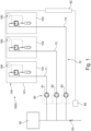
- FIG 1 schematically illustrates an exemplary water supply system 1000.
- the water supply system 1000 may be installed in an aircraft 1 ( Figure 9 ).
- the water supply system 1000 comprises a main water supply tank 50.
- This tank 50 can be filled with (potable) water and can be installed anywhere in the aircraft 1.
- the main water supply tank 50 can be installed in a belly at a (longitudinal) centre of the aircraft 1.
- the tank 50 can be filled, for example at turnarounds of the aircraft 1, via a fill valve 55 (and/or corresponding inlet).
- the water supply system 1000 may be configured to supply water from the main water supply tank 50 to a plurality of water consumers 100.
- Figure 1 illustrates exemplarily three monuments 101, 102, 103, particularly lavatory monuments, each of which includes two water consumers in form of a faucet and a toilet, the details of which will be explained with respect to Figures 7 and 8 .
- water consumers 100 may likewise be installed alone (e.g., humidifiers or water dispensers) or in other types of monuments, such as a galley (e.g., including a water fountain, food heating device including a steamer, coffeemaker, hot water provider, or the like) or a washroom including a shower.
- a galley e.g., including a water fountain, food heating device including a steamer, coffeemaker, hot water provider, or the like
- a washroom including a shower e.g., including a water fountain, food heating device including a steamer, coffeemaker, hot water provider, or the like
- the water supply system 1000 further comprises a plurality of pressurisation units 60.
- the exemplary water supply system 1000 of Figure 1 includes three monuments 100
- the exemplary water supply system 1000 includes three pressurisation units 61, 62, 63.
- Each of the pressurisation units 61, 62, 63 conveys water to a first subset 101, 102, 103 of water consumers via a respective high-pressure water supply line 71, 72, 73.
- each of the subsets 101, 102, 103 includes two water consumers (faucet and toilet), it is to be understood that each subset 101, 102, 103 may also comprise only one water consumer as well as more than two water consumers.
- each subset 101, 102, 103 is illustrated as one monument, it is to be understood that each subset 101, 102, 103 can include more than one monument, a group of monuments, a group of water consumers irrespective of an installation in a monument, such as all faucets of adjacent monuments, or the like.
- the high-pressure water supply lines 71, 72, 73 can be installed in the aircraft 1 in any desired manner and can together form a water supply network 70.
- the water supply system 1000 comprises a control unit 80 that is configured to control an output pressure of each one of the pressurisation units 60 depending on a hydraulic resistance of the associated high-pressure water supply line 70.
- the pressurisation unit 61 can be controlled to convey water from the main water supply tank via water supply line 71 to the first subset 101 of water consumers at an output pressure depending on the hydraulic resistance of the water supply line 71. This allows achieving a water flow rate and water pressure at the water consumer(s) of the first subset 101 that is optimised for this first subset 101.
- a pressure loss will occur that depends specifically on the hydraulic resistance of the line 71.
- the exemplary diagram is based on a water supply line 71 having an inner diameter of 4 mm.
- the pressure difference which equals the pressure loss over the given length, increases with increasing length of the line 71 as well as increasing flow rate.
- control unit 80 can control an output water pressure of the pressurisation unit 61 on the basis of such relationship.
- an optimised water pressure as well as optimised flow rate of water can be provided at each water consumer 100.
- the control unit 80 can be informed about the water consumer 100 activated and requiring water supply from the respective pressurisation unit 60.
- a consumer controller 180 configured to transmit a signal indicating a water need or demand of one or more associated water consumers 100.
- each water consumer 100 may be equipped with a respective individual consumer controller 180, such as an electric or electronic activator for a water supply through the water consumer 100.
- a consumer controller 180 may be installed for controlling a plurality of water consumers 100, such as one or more or all water consumers 100 of a subset 101, 102, 103.
- the consumer controller 180 may comprise or be connected to a pushbutton, a contactless sensor or the like, which a user can employ to receive or use water. The consumer controller 180 can then generate a signal indicating this water usage activation and transmit the signal to the control unit 80.
- the consumer controller 180 can be electrically or electronically connected to the control unit, such as in a wired or wireless fashion.
- the consumer controller can be connected to an aircraft data network 82, which is a prerequisite for the majority of aircrafts.
- the control unit 80 can be connected to such aircraft network 82 and can receive the signal from one or more consumer controllers 180.
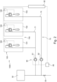
- FIG 2 schematically illustrates another exemplary water supply system 1000, which comprises components similar or identical to those of the water supply system 1000 of Figure 1 . These similar or identical features are provided with the same reference numerals and their description will be omitted for sake of brevity.
- the system of Figure 2 comprises only two pressurisation units 61, 62 and corresponding water supply lines 71, 73.
- a plurality of water consumers are grouped together and form a subset 105.
- the water consumers of two monuments 101, 102 are grouped together as a subset 105 and receive water from the same pressurisation unit 61.
- the water consumers 100 of the subset 105 may require a water supply line of substantially the same length, i.e. having a substantially similar hydraulic resistance.
- the pressurisation unit 61 can be operated with the same parameters and/or characteristics, i.e.
- the pressurisation unit 61 can be controlled (e.g., by control unit 80) to supply an output pressure sufficient for all active water consumers 100.
- Figure 2 illustrates one consumer controller 180 for each monument 101, 102, it is to be understood that a single consumer controller 180 can be employed for all water consumers 100 of this subset 105.
- FIGS 3 to 5 schematically illustrates examples of an arrangement of pressurisation units 60.
- the water supply system 1000 can further comprise another pressurisation unit 62 that conveys water to the first subset 101, 102, 103, 105.
- a plurality of pressurisation units 61, 62 can be employed to convey water to the same water supply line 70.
- two pressurisation units 61, 62 are arranged parallel to one another, in order to achieve a higher flow rate with substantially the same output pressure.
- two pressurisation units 61, 62 are arranged in series, in order to achieve a higher output pressure.
- the pressurisation units 61, 62 can be fluidly connected directly to one another or with only a short duct or pipe there between.
- the downstream pressurisation unit 62 can be arranged further away from the first pressurisation unit 61, such as after 25%, 50% or 75% of the entire length of the high-pressure water supply line 70, in order for the second pressurisation unit 62 to function as a booster pump.
- Figure 5 illustrates a further example, which involves four pressurisation units 61, 62, 63, 64.
- the pressurisation units of this example are arranged, so that they can be connected to one another pairwise in parallel or in series, and optionally with another pressurisation unit that can be connected in parallel or series.
- a cross feed valve 65 or multiway valve in a connecting line between the pressurisation units 60 can be employed to convey water from pressurisation units 61 and 63 to pressurisation unit 62 and/or 64, which allows controlling the output pressure of all pressurisation units 60 into water supply line 70.
- any desired water pressure can be achieved by operating one or more pressurisation units 61, 62, 63, 64 at one or more restrictive parameters or characteristics.
- FIG. 6 schematically illustrates details of a further exemplary water supply system 1000.
- This water supply system 1000 further comprises a pressure sensor 91, 92 (or pressure switch) in the high pressure water supply line 71, 72, respectively.
- the pressure sensor 91, 92 can be installed close to a downstream output of the pressurisation unit 61, 62.
- the control unit 80 can then be further configured to maintain an output pressure of the pressurisation unit 61, 62 at a predefined pressure level.
- the pressure sensor 91, 92 can be connected to the control unit 80, so that the control unit 80 receives a signal from the respective pressure sensor 91, 92.
- control unit 80 can solely operate on the basis of the signals from the pressure sensors 91, 92.
- the control unit 80 can control the respective pressurisation unit 61, 62 to uphold/maintain the output pressure.
- a further exemplary measure can be in form of a pressure equalising reservoir 93, 94 (or pressure maintaining reservoir) fluidly connected to the high pressure water supply line 71, 72 and configured to mechanically maintain a predefined pressure level in the high pressure water supply line 71, 72.
- This pressure equalising reservoir 93, 94 can be a simple reservoir having a gas, such as air or nitrogen, therein that is compressed if water enters the reservoir.
- the reservoir 93, 94 can include an elastic or biased element, such as a membrane or a spring-loaded piston.
- Figure 6 illustrates reservoir 93 with a spring-loaded piston, while reservoir 94 only includes gas or a membrane.
- a specific pressure is applied to the water in the water supply line 71, 72, this pressure may be maintained, if the water consumer stops water consumption. If the water consumer resumes water consumption, the pressure in the water supply line 71, 72 would drop, if no reservoir 93, 94 would be installed. Until the pressurisation unit 61, 62 can start again or can increase the output water pressure, the pressure in the water supply line 71, 72 is mechanically uphold or maintained by expanding the gas, membrane and/or spring-loaded piston in the reservoir 93, 94.
- the pressure sensor 91, 92 or pressure switch illustrated directly downstream of the corresponding pressurisation units 61, 62 can alternatively be arranged at or in the pressure equalising reservoir 93, 94.
- Figure 6 illustrates another optional feature of any of the water supply systems 1000.
- a cross feed valve 75 can be installed between the water supply lines 71, 72. This allows still using all water consumers 100 at water supply lines 71, 72, in case one of the pressurisation units 61, 62 fails. Likewise, a parallel connection of pressurisation units 61, 62 is possible by opening valve 75.
- FIG. 7 schematically illustrates details of an exemplary water consumer 100, which in this specific example comprises a faucet 110 and a toilet 120.
- the faucet 110 and the toilet 120 may likewise be referred to as water consumers 100. Since they are grouped together in this monument 100, they can also be viewed as a subset 101, 102, 103 of water consumers 100.
- the faucet 110 (with or without a water heater (not illustrated)) is connected to the water supply line 70 via a valve 112, and the toilet 120 is also connected to the water supply line 70 via a valve 127. Since a faucet 110 and a toilet 120 require different flow rates of water and, particularly, a different pressure (the toilet 120 requires a higher pressure for a shorter time period), the associated pressurisation unit 60 has to be operated with a corresponding, respective output pressure depending on whether the faucet 110 and/or the toilet 120 is activated.
- the pressurisation unit 60 may be configured to operate at an output pressure suitable for the faucet 110.
- a micro storage device 125 is installed and fluidly connected to the high pressure water supply line 70.
- the micro storage device 125 is configured to store an amount of water required for flushing a toilet 120, and to achieve a water pressure sufficient for a nozzle rinsing the toilet 120.
- valve 127 water from the water supply line 70 can be filled into the micro storage device 125, where it can build up a particular pressure.
- valve 127 is closed.
- valve 122 is opened, and the built-up pressure in micro storage device 125 releases the water through a nozzle (not explicitly illustrated) flushing the toilet 120.
- the micro storage device 125 may be equipped with a biasing element, such as the reservoir 93, 94, in order to facilitate a fast release of the water from the micro storage device 125 under the required pressure.
- a biasing element such as the reservoir 93, 94
- FIG 8 schematically illustrates details of another exemplary water consumer 100.
- the water consumer 100 is also a lavatory monument comprising a faucet 110 and a toilet 120.
- the toilet 120 is solely connected to the water supply line 70 via a corresponding valve 122.
- the output pressure of the associated pressurisation unit 60 may be controlled in such a manner that flushing the toilet can easily be achieved.
- the exemplary lavatory monument 100 includes a water buffer tank 115 and a water conveying device 114 configured to convey water from the water buffer tank 115 to the faucet 110.
- the water buffer tank 115 can be an unpressurised tank, which is only filled via valve 117 from the high-pressure water supply line 70.
- the faucet can be used anytime, irrespective of whether water is supplied via water supply line 70.
- the water buffer tank 115 can be (re-) filled timely independent from its usage.
- the water buffer tank 115 may further be equipped with a water heater (not explicitly illustrated).
- a consumer controller 180 can be configured to control a valve 112, 117, 122, 127 to operate the respective water consumer (faucet 110 or toilet 120) and/or fill the micro storage device 125 and/or water buffer tank 115.
- the valves 112, 117, 122, 127 can provide the consumer controller 180 with information about their respective state, such as opened or closed.
- the consumer controller 180 may be connected to the water conveying device 114, in order to operate the same or receive a signal therefrom about the state of the water conveying device 114.
- the micro storage device 125 and/or water buffer tank 115 can include a respective water level measuring device indicating a water level in the micro storage device 125 or water buffer tank 115.
- the consumer controller 180 may comprise or be connected to such water level measuring device, for example, in order to control one or more of the valves 117, 127.
- the consumer controller 180 can be configured to generate and transmit a signal to the control unit 80, which signal indicates a water consumption, the state of a valve 112, 117, 122, 127, a water level in the micro storage device 125, a water level in the water buffer tank 115 or other information about the water consumers 100.
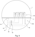
- FIG 9 schematically illustrates an aircraft 1 comprising a water supply system 1000.
- portions of the water supply system 1000 can be arranged in a bottom region of the aircraft 1, such as a cargo deck below floor 5.
- the main water tank 50 and the pressurisation units 60 can be installed in the lower deck.
- the main water tank 50 can be filled via an inlet 57 and a fill valve 55.
- a control unit 80 can be arranged close to the pressurisation units 60, such as in the lower deck of the aircraft 1.
- the water consumers 100 are mainly arranged in an upper deck, i.e. above the floor 5. However, water consumers 100 can likewise be installed in a lower deck, such as a lower deck toilet reachable through a stair case.
- a substantially or mainly vertical pipe routing can be applied between the main water tank 50 and the associated monument(s).
- the high-pressure water supply line(s) 70 could then be provided with a larger inner diameter, i.e. greater than 4 mm or greater than 6 mm. This would allow draining the water supply line(s) 70 by gravity.
- An aircraft network 82 may be installed anywhere in the aircraft, and particularly runs through the aircraft in a longitudinal direction. Thus, irrespective of a location of a water consumer 100 along the longitudinal axis of the aircraft 1, the control unit 80 can be connected to the aircraft network 82, and also anywhere along the longitudinal axis of the aircraft 1.
- Such high-pressure water supply system 1000 for an aircraft 1 allows a simplified water supply system with respect to arrangement of the pressurisation units 60 as well as running the network of water supply lines 70.
- the pressurisation units 60 by controlling the pressurisation units 60 based on a hydraulic resistance of the corresponding water supply lines and optionally other factors, different models of supplying water to water consumers 100 can be embedded.
- the pressurisation units 60 can be controlled on the basis of a type and number of water consumers 100 used at the same time, a location of the water consumer 100 in the aircraft 1 (e.g., a position of the water consumer 100 having a particular distance from the pressurisation unit 60 and requiring a certain length for the water supply line 70), a passenger class (first class, business class, economy class or the like) associated with the subset of water consumers, a time of day or time of flight (daylight, night, sleeping phases, food service phases, etc.), and the like.
- a location of the water consumer 100 in the aircraft 1 e.g., a position of the water consumer 100 having a particular distance from the pressurisation unit 60 and requiring a certain length for the water supply line 70
- a passenger class first class, business class, economy class or the like
- time of day or time of flight daylight, night, sleeping phases, food service phases, etc.
- a proportional valve or pressure reducer can be employed with this particular water consumer 100.
- the hydraulic resistance of the water supply line 70 requires a certain output pressure, but the minimum pressure value arriving at the subset 101, 102, 103, 105 of water consumers 100 still being too high for a particular water consumer 100, that particular water consumer 100 may be supplied with a restricted water pressure by employing a proportional valve or pressure reducer.
- adjustable pressure restrictors can be employed at such water consumers 100. Such adjustable pressure restrictors could further be connected to the control unit 80, which is further configured to control a pressure restriction of the respective adjustable pressure restrictor.
Landscapes
- Engineering & Computer Science (AREA)
- Health & Medical Sciences (AREA)
- Life Sciences & Earth Sciences (AREA)
- Hydrology & Water Resources (AREA)
- Public Health (AREA)
- Water Supply & Treatment (AREA)
- Physics & Mathematics (AREA)
- Aviation & Aerospace Engineering (AREA)
- Fluid Mechanics (AREA)
- General Physics & Mathematics (AREA)
- Automation & Control Theory (AREA)
- Sanitary Device For Flush Toilet (AREA)
Abstract
Description
- The present disclosure generally relates to a high pressure water supply system for an aircraft and an aircraft having such water supply system. Particularly, the present disclosure relates to a water supply system comprising a plurality of pressurisation units, each conveying water to one more of a plurality of water consumers, wherein an output pressure of the pressurisation units is controlled based on a hydraulic resistance of a high pressure water supply line between the respective pressurisation unit and the water consumer. Furthermore, the present disclosure relates to an aircraft comprising such water supply system.
- A conventional water supply system for aircrafts includes a central water tank and a water conveying device supplying water to all water consumers in the aircraft. Such water consumers include lavatory monuments (e.g. having a faucet and a toilet) and galleys (e.g. having a faucet, a hot water dispenser, food preparation devices, etc.).
- The water conveying device is designed to provide a sufficient amount of water to all water consumers (sufficient water flow rate), and to provide the necessary overall water pressure for the entire system. As a mere example, a rinsing nozzle for a toilet usually requires a higher water pressure than a faucet. Moreover, a monument further away from the central water conveying device requires a higher water pressure due to the pressure loss in the water supply duct. The central water conveying device, hence, is designed for a maximum water pressure depending on the highest pressure demand, and pressure reducers are installed at water consumers that do not require the maximum water pressure.
- Thus, the water supply system for an aircraft is usually overdesigned and, hence, requires extensive energy and involves high costs.
- It is therefore an object of the present disclosure to provide a simplified water supply system.
- This object is solved by the present invention as defined in the independent claims. Preferred embodiments are defined by the dependent claims.
- According to a first aspect to better understand the present disclosure, a high pressure water supply system for an aircraft comprises a main water supply tank, a plurality of water consumers, a plurality of pressurisation units configured to convey water from the main water supply tank to the plurality of water consumers, and a control unit.
- The water supply system, particularly, includes one pressurisation unit of the plurality of pressurisation units that conveys water to a first subset of water consumers of the plurality of water consumers via a corresponding high pressure water supply line. The control unit is configured to control an output pressure of said one pressurisation unit depending on a hydraulic resistance of the high pressure water supply line. The hydraulic resistance is based on a length, inner diameter, inner surface roughness, and number and types of bends of the high pressure water supply line, as well as a difference in height between pressurisation unit and water consumers and flow rate currently used.
- This provides for a simplified water supply system. Particularly, since the output pressure depends on a hydraulic resistance of the high-pressure water supply line (e.g., only a length of the water supply line or one or more further parameters characterising the water supply line), the entire water supply system does not need to be "overdesigned". In addition, pressure reducers can be omitted, for example, if the first subset of water consumers is connected to the one pressurisation unit via a water supply line of substantially same hydraulic resistance and/or if the first subset of water consumers requires a similar water pressure. A "substantially same hydraulic resistance" of the water supply lines in this disclosure means a hydraulic resistance difference of two water supply lines of +/-5%, +/-10% or +/-20%. As a mere example, assuming the distance between the one pressurisation unit and a water consumer of the first subset is about 20 m and requiring several bends in the water supply line, which has an inner diameter of 4 mm, another water consumer of the same first subset having a water supply line length of 18 m to 22 m, or 16 m to 24 m with similar number of bends and of same in a diameter, would still fall under "substantially same hydraulic resistance".
- Since more than one water consumer may have a water supply demand (i.e. the water consumers are activated) at the same time, the control unit can be configured to control the pressurisation unit in accordance with the hydraulic resistance specific for one of these activated water consumers. This may require that other water consumers, such as sensible water consumers or water consumers requiring a rather low-pressure, can be equipped with a throttling device or pressure reducer. Likewise, water consumers connected to a rather short supply line or of rather low hydraulic resistance may also be equipped with a throttling device or pressure reducer, also referred to as an (adjustable) restrictor as a mere example, a proportional valve could be employed and/or other active restrictors, so that a dynamic adjustment of the water pressure at each individual water consumer can be provided. This allows a hydraulic balancing of all water consumers, while achieving an optimised pressurisation unit operation.
- A pressurisation unit of the plurality of pressurisation units can be a pump, a positive displacement pump (such as a gear pump, membrane pump, piston pump, impeller pump), a centrifugal pump (such as an impeller pump or a site channel pump), a compressor, a micro-pump, or any other fluid conveying device.
- In an implementation variant, each of the plurality of water consumers can be supplied with high pressure water from a respective one of the plurality of pressurisation units via a respective high pressure water supply line. In other words, the number of pressurisation units is equal to the number of water consumers. This allows installing small pressurisation units, such as micro-pumps, since only a small amount of water has to be conveyed at a predefined pressure. In addition, any variable control of a flow rate or pressure of the pressurisation unit can be omitted, since such parameters can be preset.
- Alternatively, the first subset of water consumers can comprise two or more water consumers of the plurality of water consumers. For instance, the two or more water consumers may form a group of water consumers that are similar or have a particular characteristic in common, such as water consumers in the same monument, and/or water consumers in different monuments in a region of the aircraft requiring a water supply line of substantially same hydraulic resistance, and/or the same type of water consumers in a region of the aircraft requiring a water supply line of substantially same hydraulic resistance. As a mere example, the same type of water consumers in the first subset can be all faucets that are spatially close to one another, such as faucets of adjacent lavatories and/or galleys. This allows providing a pressurisation unit for the particular first subset of water consumers that can be operated in the same manner for each of the water consumers, which simplifies control of the pressurisation unit or allows omitting any control, but preset parameters of the pressurisation unit. For instance, if one pressurisation unit supplies water to a small number of faucets or other water consumers of same type, the pressurisation unit can be operated with the same parameters or characteristics independent of which water consumer is currently running.
- It is to be understood that in case of multiple water consumers of the same subset or group running at the same time, the control unit is further configured to control an output pressure of the pressurisation unit associated with this subset or group depending on the number of concurrently running water consumers. Nevertheless, a main factor for the required output pressure is the hydraulic resistance of the associated water supply line running from the pressurisation unit to the subset or group of water consumers.
- In another implementation variant, the water supply system can further comprise a second subset of water consumers of the plurality of water consumers, the second subset comprising one or more water consumers. In other words, the plurality of water consumers is divided into a first and second subset. It is to be understood that the number of subsets is not restricted to two, but that the present disclosure covers any number of subsets. Each subset can be supplied with water from a respective pressurisation unit of the plurality of pressurisation units.
- In a further implementation variant, the control unit can be further configured to control an output pressure of each of the plurality of pressurisation units depending on a hydraulic resistance of the respective high pressure water supply line. Thus, the water supply system is simplified by allowing installation of a plurality of pressurisation units, each being operated with preset parameters or conditions, depending on the water consumers associated with the respective pressurisation unit.
- In yet a further implementation variant, the control unit can be further configured to control the output pressure of one or more of the plurality of pressurisation units depending on a type of water consumer that is currently activated, i.e. that needs a water supply, a number of water consumers being currently activated, i.e. that need a water supply simultaneously, or other characteristics of the water consumers.
- In another implementation variant, another pressurisation unit of the plurality of pressurisation units can convey water to the first subset of water consumers via the corresponding high pressure water supply line. Thus, the other pressurisation unit can be employed to increase a flow rate and/or output pressure in the high-pressure water supply line to the first subset of water consumers.
- For instance, the other pressurisation unit can be fluidly connected to the one pressurisation unit in parallel or in series. This allows an increase of flow rate and pressure, respectively.
- It is to be understood that more than two pressurisation units can be connected to one another in parallel and/or in series or combinations thereof, in order to achieve a desired flow rate and/or output pressure.
- Furthermore, the control unit can be further configured to control the one pressurisation unit and the other pressurisation unit depending on a required flow rate of water at the first subset of water consumers. Alternatively or additionally, the control unit can be further configured to control the one pressurisation unit depending on a required water pressure at the first subset of water consumers. For instance, if two water consumers request water at the same time, the flow rate may be increased. Likewise, if a water consumer that requires a higher pressure than other water consumers (of the same subset) requests a water demand, a higher pressure of the water supply can be provided via the multiple pressurisation units. As a mere example, in a lavatory monument, a rinsing nozzle of a toilet requires a higher pressure than a faucet installed in the same monument. This higher pressure can be achieved by controlling the other pressurisation unit to operate only in case the rinsing nozzle is activated.
- In an implementation variant, the water supply system can further comprise a pressure sensor in the high pressure water supply line. The control unit can then be further configured to maintain the output pressure of said one pressurisation unit at a predefined pressure level. This allows pressurizing the high pressure water supply line at the predefined pressure level, so that any time water is required at an associated water consumer the water has the predefined pressure level. This allows omission of any control devices at the water consumers, which control devices would otherwise send information to the control unit. Thus, all control components can be located at the pressurisation unit, which simplifies the overall system.
- In another implementation variant, the water supply system can further comprise a pressure equalising reservoir fluidly connected to the high pressure water supply line and configured to mechanically maintain the predefined pressure level in the high pressure water supply line. As a mere example, the reservoir can be any compressible or elastic element, including an elastic hose section, or any container, in which a water pressure can be built up and can be released into the high pressure water supply line, for example, until the pressurisation unit begins operating or increases its output pressure. The mechanically maintaining of the predefined pressure level can be achieved by an elastic or biased element, such as a membrane or a spring-loaded piston.
- In yet another implementation variant, at least one of the plurality of water consumers can comprise a micro storage device fluidly connected to the high pressure water supply line, configured to store an amount of water required for flushing a toilet and to achieve a water pressure sufficient for a nozzle rinsing/flushing the toilet. For instance, the micro storage device can include a mechanical water conveying means, such as an elastic element, for example, a spring-loaded piston, a membrane or other biased element. Thus, water from the high pressure water supply line may be filled into the micro storage device, e.g., an amount sufficient for flushing the toilet. When the toilet flushing is activated, the mechanical water conveying means presses the water to the nozzle for rinsing/flushing the toilet. At this time, a fluid connection to the high pressure water supply line may be open or closed, so that the flushing of the toilet is achieved under support of the water supply from the high-pressure water supply line or solely by the mechanical water conveying means. Such micro storage device allows operating the pressurisation unit associated with the toilet with a particular flow rate that may not be high enough for operating the nozzle for rinsing the toilet, but is preset in view of a flow rate required for a faucet also associated with the pressurisation unit. In other words, the pressurisation unit is preset in view of the faucet (e.g., requiring a larger amount of water at a lower pressure), while the micro storage device achieves flushing the toilet in a fast manner, but requiring a small amount of water at a higher pressure (compared to the faucet).
- In a further implementation variant, at least one of the plurality of water consumers can comprise an unpressurised water buffer tank and a water conveying device configured to convey water from the unpressurised water buffer tank to a faucet. As a mere example, the unpressurised water buffer tank and water conveying device may be associated with a faucet or similar water fountain device. The unpressurised water buffer tank is fluidly connected to the high pressure water supply line, for example, via a shutoff valve, and is vented to the ambient, so that no or only a small pressure inside the unpressurised water buffer tank can build up. For instance, a venting line or overflow line can be connected to the unpressurised water buffer tank for venting the tank to the ambient. Such venting or overflow line can have a larger diameter than the high pressure supply line, in order to avoid an unwanted pressure build-up in the buffer. A duct or pipe between the unpressurised water buffer tank, conveying device and water consumer can have a different diameter (particularly larger) as the high-pressure water supply duct. Thus, the one pressurisation unit can be operated in accordance with parameters and characteristics for another water consumer requiring a higher pressure, such as a nozzle for rinsing a toilet. Via the unpressurised water buffer tank, the faucet can be decoupled from the high-pressure water supply line (particularly with respect to the provided water pressure) in any operational state fluidly downstream of the shutoff valve for filling the unpressurised water buffer tank.
- Furthermore, the control unit can further be configured to control the pressurisation unit associated with the unpressurised water buffer tank to control and output pressure of the pressurisation unit depending on the needs to refill the unpressurised water buffer tank. Likewise, the control unit can further be configured to control the pressurisation unit depending on whether the unpressurised water buffer tank is to be refilled and a further water consumer needs a water supply at the same time.
- In yet a further implementation variant, at least one of the plurality of water consumers can comprise a consumer controller configured to transmit a signal indicating a water usage at the associated consumer, and the control unit can be further configured to receive the signal transmitted from the consumer controller and to control the output pressure of said one pressurisation unit based on the received signal. This allows operating the one pressurisation unit only if the consumer controller indicates a required water supply.
- As a mere example, the consumer controller can further specify which type of water consumer requests water, so that the control unit can adapt the output pressure of the one pressurisation unit not only depending on the hydraulic resistance of the high-pressure water supply line, but also depending on the type of water consumer. For instance, a nozzle for rinsing a toilet requires a higher pressure than a faucet or similar water consumer in a galley.
- Alternatively or additionally, the consumer controller can further identify the water consumer requesting water, which further allows the control unit to determine the hydraulic resistance of the high-pressure water supply line. As a mere example, the control unit can have a look up table or the like were the hydraulic resistance of a plurality of high-pressure water supply lines is stored together with an identification of the high-pressure water supply lines and/or the connected water consumers. The control unit can then adapt the output pressure accordingly.
- It is to be understood that the consumer controller can additionally or alternatively store the hydraulic resistance of the high-pressure water supply line connecting the associated water consumer and provide the hydraulic resistance information to the control unit either alone or together with an identity of the water consumer. Further alternatively or additionally, instead of an identity of the water consumer, a type of water consumer can be indicated by the consumer controller to the control unit. Since an aircraft usually comprises a plurality of water consumers of the same type, the control unit can determine the required water pressure and/or flow rate in accordance with the hydraulic resistance of the high-pressure water supply line and the type of water consumer.
- According to a second aspect to better understand the present disclosure, an aircraft comprises at least one water supply system of the first aspect or one of its variants and/or examples.
- Furthermore, the aircraft can comprise one or more monuments including respective water consumers.
- In an implementation variant, the aircraft can comprise a network of high-pressure water supply lines connecting the plurality of pressurisation units with the one or more monuments (which can include an internal water supply network) and/or with the plurality of water consumers (directly).
- The high-pressure water supply lines can be configured to withstand a water pressure up to 20 bar, or even up to 50 bar, which could be provided by the pressurisation unit. Such high-pressure allows provision of water supply lines having only a small diameter. As a mere example and irrespective of the aspect and implementation variant, the internal diameter of a high-pressure water supply line can be between 3 mm and 10 mm, preferably between 4 mm and 6 mm. This allows installing a plurality of such water supply lines in the aircraft, since they are space-saving and can be easily guided through installations basis of the aircraft, like electric cables.
- It is to be understood that the fluid connection between pressurisation unit and a water consumer, particularly a subset of water consumers, can consist of water supply lines having different diameters. As a mere example, in case the subset of water consumers is far away from the pressurisation unit, the main portion of the high-pressure water supply line can have an increased inner diameter, such as 6 mm to 8 mm, while the remaining water supply lines, particularly, the branches to the individual water consumers, have an inner diameter of 4 mm to 6 mm.
- In another implementation variant, the aircraft can comprise an aircraft data network. The control unit of the high-pressure water supply system can be connected to the aircraft data network. For example, this allows receiving by the control unit a signal from a water consumer and/or a consumer controller that a water supply is requested. Based on this received signal, the control unit can operate the one pressurisation unit in accordance with preset parameters or characteristics of the pressurisation unit to achieve the requested water supply (in terms of flow rate and/or pressure).
- As a mere example, the signal received by the control unit can be triggered by a decrease of filling level of a buffer or micro storage device, and/or the activation of a consumer equipment (e.g., triggered by an infrared sensor or an electrical contact etc.).
- Furthermore, once several consumers of a same subset or group are requesting water simultaneously, a prioritization of the water consumers can be implemented by the control unit, such as based on a buffer / micro storage device filling level, a class information (passenger class, such as first, business or economy class), and/or a type of the water consumer or any other parameter associated with the water consumer that is collected and can be send via the consumer controller or the data network. Different priorities are conceivable to organize the refilling and supply of the different water consumers in case of normal water supply operation and also to grant high priority and low priority in case of very high consumption phases. As a mere example, in certain times of the flight, the lavatories may give in a higher priority, or a galley may be given a higher priority during food preparation phases.
- Based on the signal and/or prioritisation, the control unit can control an output pressure of the pressurisation unit(s) associated with the water consumers currently requesting water.As a further example, the control unit can be triggered by a general signal, such as a signal initiated by a pilot panel or flight assistant panel. For instance, at the beginning of a flight or start-up of the system, the control unit can receive a initiation signal. This may trigger a certain protocol or mode to fill buffer tanks or micro storage devices, depending on their filling level, and/or to flush all toilets once or the like. Here the prioritisation of each water consumer may be taken into account by the protocol or mode and, hence, by the control unit.
- In a further implementation variant, the control unit can be further configured to perform special high-pressure protocols. This is particularly possible, as most of the individual water consumers are not equipped with a water restrictor or similar pressure reducer. For example, a high-pressure toilet cleaning, a high flow water faucet (e.g., to fill a drowning device for overheated or burning batteries), and/or a high-pressure fire extinguisher can be operated with a high water pressure supplied by one or more pressurisation units and via the corresponding high-pressure water supply line.
- In yet a further implementation variant, the control unit can be further configured to determine a pump performance, for example, to compensate for biofilm growth or scaling of a valve or the water supply line, et cetera. Such determination may be sensor based, based on a time of operation of the individual devices, and/or based on a manual observation and corresponding adjustment signal provided to the control unit. Thus, the output pressure of the pressurisation unit can be adjusted or adapted to certain circumstances determined by the control unit.
- The present disclosure is not restricted to the aspects and variants in the described form and order. Specifically, the description of aspects and variants is not to be understood as a specific limiting grouping of features. It is to be understood that the present disclosure also covers combinations of the aspects and variants. Thus, each variant or optional feature can be combined with any other aspect, variant, optional feature or even combinations thereof.
- In the following, the present disclosure will further be described with reference to exemplary implementations illustrated in the figures, in which:
- Figure 1
- schematically illustrates an exemplary water supply system;
- Figure 2
- schematically illustrates another exemplary water supply system;
- Figures 3 to 5
- schematically illustrates examples of an arrangement of pressurisation units;
- Figure 6
- schematically illustrates details of a further exemplary water supply system;
- Figure 7
- schematically illustrates details of an exemplary water consumer;
- Figure 8
- schematically illustrates details of another exemplary water consumer; and
- Figure 9
- schematically illustrates an aircraft comprising a water supply system.
- In the following description, for purposes of explanation and not limitation, specific details are set forth in order to provide a thorough understanding of the present disclosure. It will be apparent to one skilled in the art that the present disclosure may be practiced in other implementations that depart from these specific details.
-
Figure 1 schematically illustrates an exemplarywater supply system 1000. Suchwater supply system 1000 may be installed in an aircraft 1 (Figure 9 ). Thewater supply system 1000 comprises a mainwater supply tank 50. Thistank 50 can be filled with (potable) water and can be installed anywhere in the aircraft 1. As a mere example, the mainwater supply tank 50 can be installed in a belly at a (longitudinal) centre of the aircraft 1. Thetank 50 can be filled, for example at turnarounds of the aircraft 1, via a fill valve 55 (and/or corresponding inlet). - The
water supply system 1000 may be configured to supply water from the mainwater supply tank 50 to a plurality ofwater consumers 100.Figure 1 illustrates exemplarily threemonuments Figures 7 and8 . It is to be understood thatwater consumers 100 may likewise be installed alone (e.g., humidifiers or water dispensers) or in other types of monuments, such as a galley (e.g., including a water fountain, food heating device including a steamer, coffeemaker, hot water provider, or the like) or a washroom including a shower. - The
water supply system 1000 further comprises a plurality ofpressurisation units 60. As the exemplarywater supply system 1000 ofFigure 1 includes threemonuments 100, the exemplarywater supply system 1000 includes threepressurisation units pressurisation units first subset water supply line subsets subset subset subset - The high-pressure
water supply lines water supply network 70. - Furthermore, the
water supply system 1000 comprises acontrol unit 80 that is configured to control an output pressure of each one of thepressurisation units 60 depending on a hydraulic resistance of the associated high-pressurewater supply line 70. As a mere example, thepressurisation unit 61 can be controlled to convey water from the main water supply tank viawater supply line 71 to thefirst subset 101 of water consumers at an output pressure depending on the hydraulic resistance of thewater supply line 71. This allows achieving a water flow rate and water pressure at the water consumer(s) of thefirst subset 101 that is optimised for thisfirst subset 101. Particularly, due to the hydraulic resistance of thewater supply line 71, a pressure loss will occur that depends specifically on the hydraulic resistance of theline 71. - Below is a diagram illustrating an exemplary relationship between flow rate and pressure difference depending on the lengths of the water supply line 71 (the length of the
water supply line 71 being one factor influencing the hydraulic resistance). The exemplary diagram is based on awater supply line 71 having an inner diameter of 4 mm.
- As can be derived from this diagram, the pressure difference, which equals the pressure loss over the given length, increases with increasing length of the
line 71 as well as increasing flow rate. - Thus, the
control unit 80 can control an output water pressure of thepressurisation unit 61 on the basis of such relationship. As a mere example, thepressurisation unit 61 can be operated (controlled bycontroller unit 80 to convey water) with an output pressure according to:
pressurisation unit 60, Ploss is the pressure loss in thepipe 70 depending on the hydraulic resistance (e.g., length, etc.) of the pipe 70 (as well as depending on the required flow rate at the water consumer), and Pconsumer is the required water pressure at the water consumer of therespective subset - By providing one
pressurisation unit 60 for eachsubset water consumer 100. - In order to allow the
control unit 80 to control eachpressurisation unit 60 to provide the optimised water pressure, thecontrol unit 80 can be informed about thewater consumer 100 activated and requiring water supply from therespective pressurisation unit 60. This can be achieved by aconsumer controller 180 configured to transmit a signal indicating a water need or demand of one or more associatedwater consumers 100. For instance, eachwater consumer 100 may be equipped with a respectiveindividual consumer controller 180, such as an electric or electronic activator for a water supply through thewater consumer 100. Alternatively or additionally, aconsumer controller 180 may be installed for controlling a plurality ofwater consumers 100, such as one or more or allwater consumers 100 of asubset - As a mere example, the
consumer controller 180 may comprise or be connected to a pushbutton, a contactless sensor or the like, which a user can employ to receive or use water. Theconsumer controller 180 can then generate a signal indicating this water usage activation and transmit the signal to thecontrol unit 80. For example, theconsumer controller 180 can be electrically or electronically connected to the control unit, such as in a wired or wireless fashion. Alternatively or additionally, the consumer controller can be connected to anaircraft data network 82, which is a prerequisite for the majority of aircrafts. Likewise, thecontrol unit 80 can be connected tosuch aircraft network 82 and can receive the signal from one ormore consumer controllers 180. -
Figure 2 schematically illustrates another exemplarywater supply system 1000, which comprises components similar or identical to those of thewater supply system 1000 ofFigure 1 . These similar or identical features are provided with the same reference numerals and their description will be omitted for sake of brevity. - The difference between the water supply systems of
Figures 1 and2 is that the system ofFigure 2 comprises only twopressurisation units water supply lines Figure 2 , a plurality of water consumers are grouped together and form asubset 105. In the illustrated example, the water consumers of twomonuments subset 105 and receive water from thesame pressurisation unit 61. For example, thewater consumers 100 of thesubset 105 may require a water supply line of substantially the same length, i.e. having a substantially similar hydraulic resistance. Thus, thepressurisation unit 61 can be operated with the same parameters and/or characteristics, i.e. can be operated to output the same water pressure, for eachwater consumer 100 in thesubset 105. Furthermore, in case more than onewater consumer 100 of thesubset 105 is activated at the same time, thepressurisation unit 61 can be controlled (e.g., by control unit 80) to supply an output pressure sufficient for allactive water consumers 100. - Although
Figure 2 illustrates oneconsumer controller 180 for eachmonument single consumer controller 180 can be employed for allwater consumers 100 of thissubset 105. -
Figures 3 to 5 schematically illustrates examples of an arrangement ofpressurisation units 60. Specifically, while one ormore water consumers 100 can be supplied with water from a single pressurisation unit, thewater supply system 1000 can further comprise anotherpressurisation unit 62 that conveys water to thefirst subset pressurisation units water supply line 70. - In
Figure 3 , twopressurisation units Figure 4 , twopressurisation units Figure 4 , thepressurisation units downstream pressurisation unit 62 can be arranged further away from thefirst pressurisation unit 61, such as after 25%, 50% or 75% of the entire length of the high-pressurewater supply line 70, in order for thesecond pressurisation unit 62 to function as a booster pump. -
Figure 5 illustrates a further example, which involves fourpressurisation units cross feed valve 65 or multiway valve in a connecting line between thepressurisation units 60 can be employed to convey water frompressurisation units pressurisation unit 62 and/or 64, which allows controlling the output pressure of allpressurisation units 60 intowater supply line 70. Thus, any desired water pressure can be achieved by operating one ormore pressurisation units -
Figure 6 schematically illustrates details of a further exemplarywater supply system 1000. Thiswater supply system 1000 further comprises apressure sensor 91, 92 (or pressure switch) in the high pressurewater supply line pressure sensor pressurisation unit control unit 80 can then be further configured to maintain an output pressure of thepressurisation unit pressure sensor control unit 80, so that thecontrol unit 80 receives a signal from therespective pressure sensor consumer controller 180, as thecontrol unit 80 can solely operate on the basis of the signals from thepressure sensors water supply line 71, 72 (measured by therespective pressure sensor 91, 92) thecontrol unit 80 can control therespective pressurisation unit - A further exemplary measure can be in form of a
pressure equalising reservoir 93, 94 (or pressure maintaining reservoir) fluidly connected to the high pressurewater supply line water supply line pressure equalising reservoir reservoir Figure 6 illustratesreservoir 93 with a spring-loaded piston, whilereservoir 94 only includes gas or a membrane. For instance, if a specific pressure is applied to the water in thewater supply line water supply line reservoir pressurisation unit water supply line reservoir - The
pressure sensor corresponding pressurisation units pressure equalising reservoir - Furthermore,
Figure 6 illustrates another optional feature of any of thewater supply systems 1000. For instance, across feed valve 75 can be installed between thewater supply lines water consumers 100 atwater supply lines pressurisation units pressurisation units valve 75. -
Figure 7 schematically illustrates details of anexemplary water consumer 100, which in this specific example comprises afaucet 110 and atoilet 120. Thefaucet 110 and thetoilet 120 may likewise be referred to aswater consumers 100. Since they are grouped together in thismonument 100, they can also be viewed as asubset water consumers 100. - In any case, the faucet 110 (with or without a water heater (not illustrated)) is connected to the
water supply line 70 via avalve 112, and thetoilet 120 is also connected to thewater supply line 70 via avalve 127. Since afaucet 110 and atoilet 120 require different flow rates of water and, particularly, a different pressure (thetoilet 120 requires a higher pressure for a shorter time period), the associatedpressurisation unit 60 has to be operated with a corresponding, respective output pressure depending on whether thefaucet 110 and/or thetoilet 120 is activated. - If such operation of the
pressurisation unit 60 is not desired, thepressurisation unit 60 may be configured to operate at an output pressure suitable for thefaucet 110. In order to correctly flush the toilet, amicro storage device 125 is installed and fluidly connected to the high pressurewater supply line 70. Themicro storage device 125 is configured to store an amount of water required for flushing atoilet 120, and to achieve a water pressure sufficient for a nozzle rinsing thetoilet 120. For example, by openingvalve 127, water from thewater supply line 70 can be filled into themicro storage device 125, where it can build up a particular pressure. Thenvalve 127 is closed. When thetoilet 120 is flushed,valve 122 is opened, and the built-up pressure inmicro storage device 125 releases the water through a nozzle (not explicitly illustrated) flushing thetoilet 120. - As a mere example, the
micro storage device 125 may be equipped with a biasing element, such as thereservoir micro storage device 125 under the required pressure. -
Figure 8 schematically illustrates details of anotherexemplary water consumer 100. In this case, thewater consumer 100 is also a lavatory monument comprising afaucet 110 and atoilet 120. In this case, thetoilet 120 is solely connected to thewater supply line 70 via acorresponding valve 122. Thus, the output pressure of the associatedpressurisation unit 60 may be controlled in such a manner that flushing the toilet can easily be achieved. - However, such pressure may be too high for the water outlet at the
faucet 110 or a water heater (not illustrated) implemented together with thefaucet 110. Thus, theexemplary lavatory monument 100 includes awater buffer tank 115 and awater conveying device 114 configured to convey water from thewater buffer tank 115 to thefaucet 110. Thewater buffer tank 115 can be an unpressurised tank, which is only filled viavalve 117 from the high-pressurewater supply line 70. Thus, the faucet can be used anytime, irrespective of whether water is supplied viawater supply line 70. As a mere example, thewater buffer tank 115 can be (re-) filled timely independent from its usage. In addition, thewater buffer tank 115 may further be equipped with a water heater (not explicitly illustrated). - In any of the examples illustrated in and explained with respect to
Figures 7 and8 , aconsumer controller 180 can be configured to control avalve faucet 110 or toilet 120) and/or fill themicro storage device 125 and/orwater buffer tank 115. Alternatively, thevalves consumer controller 180 with information about their respective state, such as opened or closed. In addition, theconsumer controller 180 may be connected to thewater conveying device 114, in order to operate the same or receive a signal therefrom about the state of thewater conveying device 114. Furthermore, also optionally themicro storage device 125 and/orwater buffer tank 115 can include a respective water level measuring device indicating a water level in themicro storage device 125 orwater buffer tank 115. As a mere example, theconsumer controller 180 may comprise or be connected to such water level measuring device, for example, in order to control one or more of thevalves - In any case, the
consumer controller 180 can be configured to generate and transmit a signal to thecontrol unit 80, which signal indicates a water consumption, the state of avalve micro storage device 125, a water level in thewater buffer tank 115 or other information about thewater consumers 100. -
Figure 9 schematically illustrates an aircraft 1 comprising awater supply system 1000. For instance, portions of thewater supply system 1000 can be arranged in a bottom region of the aircraft 1, such as a cargo deck belowfloor 5. Particularly, themain water tank 50 and thepressurisation units 60 can be installed in the lower deck. As illustrated, themain water tank 50 can be filled via aninlet 57 and afill valve 55. Acontrol unit 80 can be arranged close to thepressurisation units 60, such as in the lower deck of the aircraft 1. - The
water consumers 100 are mainly arranged in an upper deck, i.e. above thefloor 5. However,water consumers 100 can likewise be installed in a lower deck, such as a lower deck toilet reachable through a stair case. - In case the
water consumers 100, particularly the associated monument(s), are located (directly) above themain water tank 50, a substantially or mainly vertical pipe routing can be applied between themain water tank 50 and the associated monument(s). The high-pressure water supply line(s) 70 could then be provided with a larger inner diameter, i.e. greater than 4 mm or greater than 6 mm. This would allow draining the water supply line(s) 70 by gravity. - An
aircraft network 82 may be installed anywhere in the aircraft, and particularly runs through the aircraft in a longitudinal direction. Thus, irrespective of a location of awater consumer 100 along the longitudinal axis of the aircraft 1, thecontrol unit 80 can be connected to theaircraft network 82, and also anywhere along the longitudinal axis of the aircraft 1. - Such high-pressure
water supply system 1000 for an aircraft 1 allows a simplified water supply system with respect to arrangement of thepressurisation units 60 as well as running the network ofwater supply lines 70. In addition, by controlling thepressurisation units 60 based on a hydraulic resistance of the corresponding water supply lines and optionally other factors, different models of supplying water towater consumers 100 can be embedded. - As mere examples, the
pressurisation units 60 can be controlled on the basis of a type and number ofwater consumers 100 used at the same time, a location of thewater consumer 100 in the aircraft 1 (e.g., a position of thewater consumer 100 having a particular distance from thepressurisation unit 60 and requiring a certain length for the water supply line 70), a passenger class (first class, business class, economy class or the like) associated with the subset of water consumers, a time of day or time of flight (daylight, night, sleeping phases, food service phases, etc.), and the like. - Furthermore, in case one or
more water consumers 100 of aparticular subset respective water consumer 100, a proportional valve or pressure reducer can be employed with thisparticular water consumer 100. In other words, if the hydraulic resistance of thewater supply line 70 requires a certain output pressure, but the minimum pressure value arriving at thesubset water consumers 100 still being too high for aparticular water consumer 100, thatparticular water consumer 100 may be supplied with a restricted water pressure by employing a proportional valve or pressure reducer. - Likewise, adjustable pressure restrictors (not illustrated) can be employed at
such water consumers 100. Such adjustable pressure restrictors could further be connected to thecontrol unit 80, which is further configured to control a pressure restriction of the respective adjustable pressure restrictor. - It is believed that the advantages of the technique presented herein will be fully understood from the foregoing description, and it will be apparent that various changes may be made in the form, constructions and arrangement of the exemplary aspects thereof without departing from the scope of the disclosure or without sacrificing all of its advantageous effects. Because the technique presented herein can be varied in many ways, it will be recognized that the disclosure should be limited only by the scope of the claims that follow.
Claims (10)
- A high pressure water supply system (1000) for an aircraft (1), comprising:a main water supply tank (50);a plurality of water consumers (100);a plurality of pressurisation units (60) configured to convey water from the main water supply tank (50) to the plurality of water consumers (100); anda control unit (80),characterised in thatone pressurisation unit (61) of the plurality of pressurisation units (60) conveys water to a first subset (101, 105) of water consumers of the plurality of water consumers (100) via a corresponding high pressure water supply line (71),the control unit (80) is configured to control an output pressure of said one pressurisation unit (61) depending on a hydraulic resistance of the high pressure water supply line (71).
- The water supply system of claim 1, wherein each of the plurality of water consumers (100) is supplied with high pressure water from a respective one of the plurality of pressurisation units (60) via a respective high pressure water supply line (70), orwherein the first subset (101, 105) of water consumers comprises two or more water consumers (100) of the plurality of water consumers (100), and/orwherein the water supply system further comprises a second subset (102, 105) of water consumers of the plurality of water consumers (100), the second subset comprising one or more water consumers (100).
- The water supply system of claim 2, wherein the control unit (80) is further configured to control an output pressure of each of the plurality of pressurisation units (60) depending on a hydraulic resistance of the respective high pressure water supply line (70).
- The water supply system one of claims 1 to 3, wherein another pressurisation unit (62) of the plurality of pressurisation units (60) conveys water to the first subset (101, 105) of water consumers via the corresponding high pressure water supply line (71),wherein the other pressurisation unit (62) is fluidly connected to the one pressurisation unit (61) in parallel or in series, andwherein the control unit (180) is further configured to control the one pressurisation unit (61) and the other pressurisation unit (62) depending on a required flow rate of water at the first subset of water consumers.
- The water supply system one of claims 1 to 4, further comprising:a pressure sensor (91, 92) in the high pressure water supply line (71),wherein the control unit (80) is further configured to maintain the output pressure of said one pressurisation unit (61) at a predefined pressure level.
- The water supply system of claim 5, further comprising:
a pressure equalising reservoir (93, 94) fluidly connected to the high pressure water supply line (71) and configured to mechanically maintain the predefined pressure level in the high pressure water supply line (71). - The water supply system of one of claims 1 to 6, wherein at least one of the plurality of water consumers (100) comprises a micro storage device (125) fluidly connected to the high pressure water supply line (71), configured to store an amount of water required for flushing a toilet, and to achieve a water pressure sufficient for a nozzle rinsing the toilet.
- The water supply system of one of claims 1 to 7, wherein at least one of the plurality of water consumers (100) comprises an unpressurised water buffer tank (115) and a water conveying device (114) configured to convey water from the unpressurised water buffer tank (115) to a faucet (110).
- The water supply system of one of claims 1 to 8, wherein at least one of the plurality of water consumers (100) comprises a consumer controller (180) configured to transmit a signal indicating a water usage at the associated consumer, and
wherein the control unit (80) is further configured to receive the signal transmitted from the consumer controller (180) and to control the pump output pressure of said one pressurisation unit (61) based on the received signal. - An aircraft (1) comprising a water supply system (1000) of one of claims 1 to 9.
Priority Applications (2)
| Application Number | Priority Date | Filing Date | Title |
|---|---|---|---|
| EP23181043.3A EP4480819A1 (en) | 2023-06-22 | 2023-06-22 | High pressure water supply system and aircraft equipped with such system |
| US18/749,706 US12534887B2 (en) | 2023-06-22 | 2024-06-21 | High pressure water supply system and aircraft equipped with such system |
Applications Claiming Priority (1)
| Application Number | Priority Date | Filing Date | Title |
|---|---|---|---|
| EP23181043.3A EP4480819A1 (en) | 2023-06-22 | 2023-06-22 | High pressure water supply system and aircraft equipped with such system |
Publications (1)
| Publication Number | Publication Date |
|---|---|
| EP4480819A1 true EP4480819A1 (en) | 2024-12-25 |
Family
ID=86942581
Family Applications (1)
| Application Number | Title | Priority Date | Filing Date |
|---|---|---|---|
| EP23181043.3A Pending EP4480819A1 (en) | 2023-06-22 | 2023-06-22 | High pressure water supply system and aircraft equipped with such system |
Country Status (2)
| Country | Link |
|---|---|
| US (1) | US12534887B2 (en) |
| EP (1) | EP4480819A1 (en) |
Citations (4)
| Publication number | Priority date | Publication date | Assignee | Title |
|---|---|---|---|---|
| US20180238765A1 (en) * | 2017-02-22 | 2018-08-23 | Max H. GRAMESPACHER | Method and system for water metering and unusual water flow detection |
| US20180291595A1 (en) * | 2017-04-07 | 2018-10-11 | Airbus Operations Gmbh | Aircraft comprising a high-pressure water supply and distribution system |
| US20220342431A1 (en) * | 2021-04-23 | 2022-10-27 | Airbus Operations Gmbh | Water supply system for an aircraft |
| US20220404228A1 (en) * | 2021-06-18 | 2022-12-22 | The Boeing Company | Water leak detection systems and methods for an internal cabin of an aircraft |
Family Cites Families (4)
| Publication number | Priority date | Publication date | Assignee | Title |
|---|---|---|---|---|
| US20040186634A1 (en) * | 2003-03-17 | 2004-09-23 | Lucky Patrick W. | Adaptive potable water fill system for an aircraft |
| CA2984308C (en) * | 2017-10-27 | 2021-01-05 | International Water-Guard Industries Inc. | Methods and systems for supplying water to an aircraft |
| US11726505B2 (en) * | 2020-01-21 | 2023-08-15 | Mag Aerospace Industries, Llc | Water control system for aircraft |
| DE102021128133A1 (en) * | 2021-10-28 | 2023-05-04 | Diehl Aviation Gilching Gmbh | Water supply system for an aircraft |
-
2023
- 2023-06-22 EP EP23181043.3A patent/EP4480819A1/en active Pending
-
2024
- 2024-06-21 US US18/749,706 patent/US12534887B2/en active Active
Patent Citations (4)
| Publication number | Priority date | Publication date | Assignee | Title |
|---|---|---|---|---|
| US20180238765A1 (en) * | 2017-02-22 | 2018-08-23 | Max H. GRAMESPACHER | Method and system for water metering and unusual water flow detection |
| US20180291595A1 (en) * | 2017-04-07 | 2018-10-11 | Airbus Operations Gmbh | Aircraft comprising a high-pressure water supply and distribution system |
| US20220342431A1 (en) * | 2021-04-23 | 2022-10-27 | Airbus Operations Gmbh | Water supply system for an aircraft |
| US20220404228A1 (en) * | 2021-06-18 | 2022-12-22 | The Boeing Company | Water leak detection systems and methods for an internal cabin of an aircraft |
Also Published As
| Publication number | Publication date |
|---|---|
| US20240426086A1 (en) | 2024-12-26 |
| US12534887B2 (en) | 2026-01-27 |
Similar Documents
| Publication | Publication Date | Title |
|---|---|---|
| JP7398791B2 (en) | Recirculating fluid heating system | |
| CN115230968A (en) | Water supply system for an aircraft | |
| EP2452875A2 (en) | Aircraft potable water system | |
| US20140010522A1 (en) | Tap water device for storing and heating tap water | |
| US9316412B2 (en) | High capacity water heater | |
| US5309938A (en) | Fresh water supply system for an aircraft | |
| CN101991921A (en) | Emergency oxygen supply device | |
| KR100813181B1 (en) | Extinguishing water supply system that does not require rooftop expensive tank and pressure tank | |
| US12534887B2 (en) | High pressure water supply system and aircraft equipped with such system | |
| US12503232B2 (en) | Method for draining a local water distribution system | |
| JP2003508314A (en) | Water tank and pump system | |
| JP6603051B2 (en) | Hot water supply system | |
| US11702832B2 (en) | Vacuum-assisted toilet systems and methods of using the same | |
| CN102213462A (en) | Device for distribution of water for heating | |
| EP4361040B1 (en) | Water supply system with cross-feed link and aircraft having a water supply system | |
| EP2902714A1 (en) | Hot-water supply system | |
| US20240425198A1 (en) | Adjustable water supply system and aircraft equipped with a water supply system | |
| US20250128817A1 (en) | Method and system for operating a pump and valve in a water supply system of an aircraft | |
| EP4650275A1 (en) | Multifunctional water supply system with buffer tank for potable water delivery | |
| GB2527751A (en) | Accumulator system | |
| WO2023031743A1 (en) | Device for saving water, in particular for showers and similar utilities | |
| US6047721A (en) | Air introduction device for a hydro-pneumatic reservoir | |
| CN120863878A (en) | aircraft sections and aircraft | |
| DK2724084T3 (en) | Device for dispensing a quantity of liquid to a withdrawal station | |
| EP4696603A1 (en) | Water supply and drainage system for an aircraft and corresponding aircraft |
Legal Events
| Date | Code | Title | Description |
|---|---|---|---|
| PUAI | Public reference made under article 153(3) epc to a published international application that has entered the european phase |
Free format text: ORIGINAL CODE: 0009012 |
|
| STAA | Information on the status of an ep patent application or granted ep patent |
Free format text: STATUS: THE APPLICATION HAS BEEN PUBLISHED |
|
| AK | Designated contracting states |
Kind code of ref document: A1 Designated state(s): AL AT BE BG CH CY CZ DE DK EE ES FI FR GB GR HR HU IE IS IT LI LT LU LV MC ME MK MT NL NO PL PT RO RS SE SI SK SM TR |
|
| STAA | Information on the status of an ep patent application or granted ep patent |
Free format text: STATUS: REQUEST FOR EXAMINATION WAS MADE |
|
| 17P | Request for examination filed |
Effective date: 20250625 |
|
| GRAP | Despatch of communication of intention to grant a patent |
Free format text: ORIGINAL CODE: EPIDOSNIGR1 |
|
| STAA | Information on the status of an ep patent application or granted ep patent |
Free format text: STATUS: GRANT OF PATENT IS INTENDED |