EP4480818A1 - Adjustable water supply system and aircraft equipped with a water supply system - Google Patents
Adjustable water supply system and aircraft equipped with a water supply system Download PDFInfo
- Publication number
- EP4480818A1 EP4480818A1 EP23181036.7A EP23181036A EP4480818A1 EP 4480818 A1 EP4480818 A1 EP 4480818A1 EP 23181036 A EP23181036 A EP 23181036A EP 4480818 A1 EP4480818 A1 EP 4480818A1
- Authority
- EP
- European Patent Office
- Prior art keywords
- water
- water supply
- consumer
- unit
- pressurisation
- Prior art date
- Legal status (The legal status is an assumption and is not a legal conclusion. Google has not performed a legal analysis and makes no representation as to the accuracy of the status listed.)
- Pending
Links
Images


Classifications
-
- B—PERFORMING OPERATIONS; TRANSPORTING
- B64—AIRCRAFT; AVIATION; COSMONAUTICS
- B64D—EQUIPMENT FOR FITTING IN OR TO AIRCRAFT; FLIGHT SUITS; PARACHUTES; ARRANGEMENT OR MOUNTING OF POWER PLANTS OR PROPULSION TRANSMISSIONS IN AIRCRAFT
- B64D11/00—Passenger or crew accommodation; Flight-deck installations not otherwise provided for
- B64D11/04—Galleys
-
- B—PERFORMING OPERATIONS; TRANSPORTING
- B64—AIRCRAFT; AVIATION; COSMONAUTICS
- B64D—EQUIPMENT FOR FITTING IN OR TO AIRCRAFT; FLIGHT SUITS; PARACHUTES; ARRANGEMENT OR MOUNTING OF POWER PLANTS OR PROPULSION TRANSMISSIONS IN AIRCRAFT
- B64D11/00—Passenger or crew accommodation; Flight-deck installations not otherwise provided for
- B64D11/02—Toilet fittings
-
- E—FIXED CONSTRUCTIONS
- E03—WATER SUPPLY; SEWERAGE
- E03B—INSTALLATIONS OR METHODS FOR OBTAINING, COLLECTING, OR DISTRIBUTING WATER
- E03B7/00—Water main or service pipe systems
- E03B7/07—Arrangement of devices, e.g. filters, flow controls, measuring devices, siphons or valves, in the pipe systems
- E03B7/075—Arrangement of devices for control of pressure or flow rate
-
- G—PHYSICS
- G05—CONTROLLING; REGULATING
- G05B—CONTROL OR REGULATING SYSTEMS IN GENERAL; FUNCTIONAL ELEMENTS OF SUCH SYSTEMS; MONITORING OR TESTING ARRANGEMENTS FOR SUCH SYSTEMS OR ELEMENTS
- G05B19/00—Program-control systems
- G05B19/02—Program-control systems electric
- G05B19/04—Program control other than numerical control, i.e. in sequence controllers or logic controllers
- G05B19/042—Program control other than numerical control, i.e. in sequence controllers or logic controllers using digital processors
-
- G—PHYSICS
- G05—CONTROLLING; REGULATING
- G05B—CONTROL OR REGULATING SYSTEMS IN GENERAL; FUNCTIONAL ELEMENTS OF SUCH SYSTEMS; MONITORING OR TESTING ARRANGEMENTS FOR SUCH SYSTEMS OR ELEMENTS
- G05B2219/00—Program-control systems
- G05B2219/20—Pc systems
- G05B2219/26—Pc applications
- G05B2219/2625—Sprinkler, irrigation, watering
Definitions
- the present disclosure generally relates to an adjustable water supply system for an aircraft and an aircraft having such water supply system.
- the present disclosure relates to a water supply system capable of controlling a pressurisation unit conveying water from a water supply tank to a plurality of water consumers, and an aircraft having such water supply system.
- a conventional water supply system for aircrafts includes a central water tank and water conveying device supplying water to all water consumers in the aircraft.
- water consumers include lavatory monuments (e.g. having a faucet and a toilet) and galleys (e.g. having a faucet, a hot water dispenser, food preparation devices, etc.).
- the water conveying device is designed to provide a sufficient amount of water to all water consumers, and provide the necessary overall water pressure.
- a rinsing nozzle for a toilet usually requires a higher water pressure than a faucet.
- the water conveying device is designed to provide the maximum water amount and pressure in the aircraft.
- a plurality of water consumers require a sufficient water supply.
- the central water conveying device hence, is further designed for this maximum supply (i.e., a maximum amount or flow rate).
- a water supply system for an aircraft region comprises a water supply tank, a plurality of water consumers, a pressurisation unit configured to convey water from the water supply tank to the plurality of water consumers, and a plurality of water consumer supply units.
- the plurality of water consumers are connected to the water supply tank via the pressurisation unit with corresponding ducts or pipes.
- Such ducts or pipes are designed to duct water under the pressure induced by the pressurisation unit.
- the pressurisation unit can be a pump, such as a unidirectional or reverse water pump, a micro pump a positive displacement pump (e.g., a membrane pump, gear pump, impeller pump) or non-positive displacement pump (e.g., a centrifugal pump) or the like.
- the pressurisation unit can be operated in a forward as well as a reverse mode.
- the aircraft region comprises a dedicated number of water consumers.
- an aircraft region can be a monument, such as a lavatory monument or a galley, or can be a group of monuments, particularly arranged spatially close to one another. This allows sharing the water supply tank between the water consumers in this aircraft region.
- Each of the plurality of water consumer supply units is configured to control water supply from the pressurisation unit to one of the plurality of water consumers. In other words, the water consumer supply units initiate water supply to the water consumers.
- each of the plurality of water consumer supply units is configured to output a consumer signal indicating a water supply of the respective water consumer.
- each water consumer supply unit can trigger a water supply to a respective water consumer.
- the water supply system comprises a control unit that is configured to receive the consumer signal of the plurality of water consumer supply units and to control a flow rate and/or pressure of the pressurisation unit depending on the consumer signal.
- the water supply system provides (conveys) water to a water consumer, only if the consumer signal is output by the respective water consumer supply unit.
- an energy supply for the pressurisation unit can be adjusted.
- a low-energy supply to the pressurisation unit can lead to a small flow rate and/or low pressure of the water provided by the pressurisation unit, while a high energy supply to the pressurisation unit can lead to a high flow rate and/or pressure of the water.
- a pump speed can be adjusted by the control unit.
- the control unit can be made aware of the water consumer (through the output consumer signal), the water supply can be adjusted in view of or adapted to the water consumer. Particularly, the flow rate and/or pressure output by the pressurisation unit can be adjusted or preset with respect to the water consumer requesting a water supply. As a mere example, if a faucet is activated, the pressurisation unit may provide a lower flow rate than in case of a rinsing nozzle of a toilet bowl being activated. Likewise, if the water consumer is a galley insert, such as a coffeemaker, the control unit can be configured to control the pressurisation unit with a constant and sufficiently high pressure and flow rate required for the coffeemaker.
- the energy used by the pressurisation pump can be significantly reduced, since not the maximum pressure and flow rate is to be provided.
- faucets have been equipped with aerators and/or pressure regulators, in order to avoid spilling due to too high pressure water output.
- the water supply system of the present disclosure does not only save energy, but further reduces sound emissions of the pressurisation unit, as it does not operate at its maximum level all the time.
- each of the plurality of water consumer supply units can be coupled to or comprise a water consumer valve configured to activate and deactivate the water supply from the pressurisation unit to the respective water consumer.
- the water consumer supply unit can, for example, control the water consumer valve.
- the water consumer supply unit can include a sensor and/or switch configured to open and close (activate and deactivate) the water consumer valve.
- the sensor and/or switch can further be configured to set an opening degree of the water consumer valve, in order to adjust the water supply (amount and/or flow rate and/or pressure).
- each of the plurality of water consumer supply units is configured to output the consumer signal further indicating the activation or deactivation of the water supply and/or an opening degree of the water consumer valve.
- the control unit can further be configured to control a flow rate of the pressurisation unit depending on the consumer signal, i.e. depending on the activation or deactivation of the water supply, and/or depending on the opening degree of the water consumer valve.
- a further optimisation of the water supply can be achieved by correspondingly controlling the pressurisation unit (i.e. the flow rate and/or pressure provided by pressurisation unit).
- the water consumer supply unit can generate the consumer signal indicating the activation and deactivation of the water supply and/or a desired opening degree of the water consumer valve.
- the control unit can then be further configured to control the water consumer valve in accordance with the consumer signal.
- the control unit can open the water consumer valve up to a desired opening degree and operate the pressurisation unit at a flow rate and/or pressure corresponding to the opening degree (including fully open, which equals an open water consumer valve) or close the water consumer valve.
- the control unit can be connected to the water consumer valve and transmit a signal to the water consumer valve indicating the opening, opening degree or closing of the water consumer valve.
- the water consumer valve may include an actuator (e.g., a motor or the like) configured to steplessly open and close the water consumer valve.
- a water consumer supply unit associated with a faucet outputs a consumer signal
- the control unit can control the water consumer valve to provide a fluid connection between the pressurisation unit and the faucet, and to further control the flow rate of the pressurisation unit in correspondence with the needs of the faucet.
- more than one water consumer supply unit can output a consumer signal, such as a rinsing switch for a toilet and a switch or sensor of a faucet.
- the control unit can control the respective water consumer valve to provide a fluid connection between the pressurisation unit and the rinsing nozzle of the toilet as well as the faucet, and further to control the flow rate of the pressurisation unit in correspondence with the combined needs of the rinsing nozzle and the faucet.
- the water supply system can further comprise a multiport water supply valve configured to activate and deactivate the water supply from the pressurisation unit to one or more of the plurality of water consumers.
- a multiport water supply valve can be configured to provide a fluid connection between a supply line from the pressurisation unit to one or more supply lines to the water consumers.
- the multiport water supply valve can be implemented as a shuttle valve.
- control unit can be further configured to control the multiport water supply valve depending on the consumer signal.
- control unit can control the multiport water supply valve to allow a fluid connection between the pressurisation unit and one or more of the plurality of water consumers depending on the consumer signal.
- the control unit can control the multiport water supply valve to provide a fluid connection between the pressurisation unit and the faucet, and to further control the flow rate of the pressurisation unit in correspondence with the needs of the faucet.
- more than one water consumer supply unit can output a consumer signal, such as a rinsing switch for a toilet and a switch or sensor of a faucet.
- control unit can control the multiport water supply valve to provide a fluid connection between the pressurisation unit and the rinsing nozzle of the toilet as well as the faucet, and further to control the flow rate of the pressurisation unit in correspondence with the combined needs of the rinsing nozzle and the faucet.
- control unit can be configured to control the flow rate and/or pressure of the pressurisation unit to a first flow rate and/or a first pressure for a first water consumer of the plurality of water consumers, and to a second flow rate and/or second pressure for a second water consumer of the plurality of water consumers, wherein the second flow rate and/or pressure is larger than the first flow rate and/or pressure.
- control unit can be configured to control the flow rate and/or pressure of the pressurisation unit to a third flow rate and/or third pressure, wherein the third flow rate and/or pressure is larger than the first and second flow rate and/or pressure.
- control unit can optionally be further configured to control the first and second flow rate and/or pressure of the pressurisation unit depending on one or more water consumer parameters.
- consumer parameters can include the type of water consumer (such as faucet, toilet, galley insert, or the like), a water supply request at the water consumer (such as high, medium or low flow rate request), or a priority level of the water consumer (such as high priority to a coffeemaker requesting continuous flow rate and pressure, or medium to high priority to a toilet in business class, etc.).
- the consumer parameter may further include a filling level of the water supply tank, although the water supply tank is not a consumer. For instance, a load filling level may be an indication for the control unit to reduce the first and/or second flow rate and/water pressure.
- control unit can be configured to control the flow rate of the pressurisation unit depending on a type of the water consumer and/or a location of the water consumer in the aircraft, for which the consumer signal is output.
- an optimisation of the flow rate can be achieved.
- some types of water consumers such as a food or beverage maker, require a constant flow rate and/or pressure of water, in order to properly function. Otherwise, food or beverage may not have the desired quality. This can be taken into account by the control unit.
- the type of the water consumer can include a faucet for a wash basin, a rinse nozzle for a toilet, and a water consuming galley insert in a galley.
- Such water consuming galley insert can be a coffeemaker, hot water dispenser, steam oven, galley faucet or the like.
- the control unit receiving a consumer signal indicating such type of water consumer can have a predefined flow rate and/or pressure of water to be supplied to such consumer type. As indicated above, some water consumer types are more sensitive to fluctuating water flow rate and/or pressure, so that the control unit controls the pressurisation unit accordingly, i.e. provides a constant flow rate and/or pressure of water via the pressurisation unit.
- control unit may either increase the flow rate and/or pressure of water provided by the pressurisation unit, and/or postpone or delay the activation of the less sensitive water consumer until the sensitive water consumer has finished its operation (does not require a dedicated water supply).
- the location of the water consumer can include a front section, middle section and rear section of the aircraft, a first or business class or economy class installed in the aircraft, lavatory monument, and/or a galley.
- the location of the water consumer may result in different priorities given to the associated water consumers.
- the control unit can, hence, control the pressurisation unit in order to provide a flow rate and/or pressure of water at each water consumer based on the priority given to the respective water consumer.
- control unit may be configured to control the pressurisation unit to provide a higher flow rate and/or pressure of water for all water consumers at this "premium location". This avoids the usually negative personal impression, if the water is supplied with a low flow rate and/or pressure.
- control unit can further be configured to control the pressurisation unit to provide a higher pressure to compensate an increased overall water consumption.
- the water supply system can further comprise a further pressurisation unit configured to convey water from the water supply tank to the plurality of water consumers.
- the further pressurisation unit also referred to as a second pressurisation unit
- the further pressurisation unit is provided in addition to the (first) pressurisation unit described so far.
- the further pressurisation unit can be connected to the water supply tank in parallel or series with the pressurisation unit.
- a parallel arrangement of the (first and second) pressurisation units allows a higher flow rate, if both pressurisation units are operating.
- Multiple pressurisation units provided in series allow increasing the pressure of water supplied by the pressurisation units.
- control unit can be further configured to control a flow rate and/or pressure of the further pressurisation unit individually or simultaneously with the pressurisation unit. Particularly, operating the (first and second) pressurisation units simultaneously, allows increasing the flow rate and/or pressure of the water supply. Operating the (first or second) pressurisation units individually, allows a flow rate and/or pressure of the water supply of a desired value.
- the further pressurisation unit can have a different throughput (water supplying power) than the (first) pressurisation unit.
- operation of one of the (first or second) pressurisation units allows providing a predefined flow rate and/or pressure of the water supply.
- control unit can be configured to control the flow rate and/or pressure of the water conveyed to the plurality of water consumers by activating or deactivating the pressurisation unit and/or the further pressurisation unit.
- a simple control of the supplied water can be achieved by switching on and off one or more pressurisation units.
- one or more power levels of the respective pressurisation unit may be predefined.
- the control unit can then activate or deactivate the respective pressurisation unit at one of the one or more power levels. This allows achieving any flow rate and/or pressure output by the plurality of pressurisation units.
- the water supply system can further comprise a refill valve coupled to a central water supply system and configured to fill water into the water supply tank.
- the refill valve is fluidly connected to a water pipe of the central water supply system. Opening the refill valve allows refilling the water supply tank.
- the operation of the refill valve can be controlled by the control unit.
- the control unit since the control unit controls the water supply based on the consumer signal(s), the control unit may evaluate or gauge or predict a water level in the water supply tank based on the current water consumption. This allows refilling water into the water supply tank corresponding to the current and/or future needs.
- control unit can be configured to control the refill valve, in order to refill the water supply tank.
- control unit can send a corresponding signal to the central water supply system, in order to inform the central water supply system of the demand of refill water.
- an aircraft comprises at least one water supply system of the first aspect or one of its variants and/or examples.
- the aircraft can comprise a central water tank, a central water conveying device configured to convey water to the at least one water supply system, and a central control device connected to the control unit and configured to output a central water supply signal.
- the central control device can be a cabin assignment module operated by a flight attendant for setting certain conditions regarding the cabin of the aircraft. As a mere example, a flight attendant may set the cabin of the aircraft into a sleeping phase mode, where the majority of passengers will sleep. During this time the light of the cabin is usually switched off.
- the control unit of the at least one water supply system can receive a corresponding information signal from the central control device, so that the respective pressurisation unit is operated in a low flow rate and/or pressure mode, in order to avoid loud sound emission from the pressurisation unit.
- the information signal from the central control device may be interpreted by the control unit to operate the pressurisation unit at 90%, 80%, 70% or even 60% for all predefined flow rate and/or pressure values.
- central control device may operate fully automatically, i.e. without flight attendant involvement.
- the central control device can be connected to the control unit via a data network or data link provided in the aircraft to communicate data and information between different central control units, flight attendant panels and/or pilot controls.
- control unit of the at least one water supply system can be further configured to receive the central water supply signal from the central control device and to control the flow rate and/or pressure of the pressurisation unit depending on the central water supply signal.
- control unit of each of the at least one water supply system can have predefined flow rates and/or pressure values for the respective water consumers, such values may be adapted or overwritten depending on the central water supply signal.
- the central water supply signal can indicate one or more of a water level of the central water tank, a remaining flight time, a high water consumption time, cabin occupancy, usage frequency of the water consumers, a flight phase, a cabin scenario (such as sleeping, wake up, washing, catering cycle, etc.), a filling level of the water supply tank of the at least one water supply system, an integral over filling levels of all water supply tanks, a filling level of the water supply tank of a prioritised one of the at least one water supply system, the general standard time (UTC), and a venting or rinsing phase of the at least one water supply system.
- a water level of the central water tank can indicate one or more of a water level of the central water tank, a remaining flight time, a high water consumption time, cabin occupancy, usage frequency of the water consumers, a flight phase, a cabin scenario (such as sleeping, wake up, washing, catering cycle, etc.), a filling level of the water supply tank of the at least one water supply system, an integral over filling
- a low water level of the central water tank may result in the control unit of each of the at least one water supply system to reduce the flow rate and/or pressure of water supply provided by the pressurisation unit.
- the control unit of each of the at least one water supply system generally reduces a flow rate and/or pressure of water supply provided by the respective pressurisation unit.
- exceptions may again be made depending on the location of the water supply system (e.g., first or economy class) and/or depending on the type of water consumer (e.g., a galley insert).
- the central water supply signal can further indicate one or more of time dependent effects of the water supply system and, particularly, the pressurisation unit of the at least one water supply system and/or the central water conveying device. For instance, hydraulic restrictions may occur over time (e.g., scaling of an aerator or nozzle, a biofilm deposit, a particle deposit, or the like). Likewise, the pump performance may be reduced over time due to ageing effects. In such case, the central water supply signal received by the control unit of the at least one water supply system allows the control unit to adapt the operation of the pressurisation unit to compensate for such differences.
- the central control device can further be configured to control the central water conveying device in accordance with a "soft start", i.e. a speed of the conveying device in accordance with a ramp curve.
- the central water conveying device may be operated in reverse mode, for example, during a drainage of the central water tank and corresponding water system of the aircraft.
- the central control device may be configured to control the central water conveying device depending on a reduced performance of the central water conveying device (e.g., due to ageing).
- the aircraft can comprise one or more monuments.
- the at least one water supply system can be installed in one of such monuments.
- a monument can be a lavatory monument having a faucet and a toilet, and/or a galley having a faucet, a hot water dispenser, a food preparation device, or the like.
- the central control device can further be configured to control the central water conveying device to convey water with a flow rate and/or pressure depending on the number of water consumers of the at least one water supply system currently running (i.e., running at the same time), the total number of water consumers currently running, an integral of a water level of each water supply tank in the at least one water supply system, and/or if one or more water supply tanks have reached a critically low water level, such as below 20% or below 10%, or even an empty tank. This allows keeping a minimum water level buffered in the water supply tank of the at least one water supply system.
- the central control device can be further configured to control the central water conveying device to convey water with a flow rate and/or pressure depending on one or more water consumer parameters.
- consumer parameters which can be derived by the central control device from the control unit of the at least one water supply system, can include the type of water consumer (such as faucet, toilet, galley insert, or the like) currently requesting water, a water supply request at the water consumer (such as high, medium or low flow rate request), or a priority level of the water consumer (such as high priority to a coffeemaker requesting continuous flow rate and pressure, or medium to high priority to a toilet in business class, etc.).
- the central control device can be further configured to control the central water conveying device on the basis of a filling level of the water supply tank of the at least one water supply system.
- This can include a prioritisation of one or more water supply tanks in case of a plurality of water supply systems.
- the water supply tank or tanks with the lowest fill level may receive water via the refill valve.
- This may include sending a corresponding signal to the control unit of the at least one water supply system identifying the priority of the respective water supply system, so that the associated control unit refills the water supply tank or waits with the refill process.
- a video surveillance unit may determine whether there is a queue in front of one of the lavatories.
- statistical data may be provided by a corresponding computing device of the aircraft. Based on such data, one of the at least one water supply system may be prioritised.
- a further option for the central control device to control the central water conveying device can be the number of refill valves currently opened at the water supply systems. In other words, if more than one water supply system is currently refilling the associated water supply tank, an increased flow rate and/or pressure can be provided by the central water conveying device.
- FIG. 1 schematically illustrates a plurality of water supply systems 100a-d, wherein one water supply system 100a is illustrated in more detail.
- each water supply system 100a-d may be associated with a particular water consumer, group of water consumers and/or monument in an aircraft.
- Water supply system 100a for example, can be associated with a lavatory monument.
- Water supply systems 100b-d can respectively be associated with a further lavatory monument, a galley, a washroom including a shower, a water dispenser niche and the like.
- the components described with respect to the water supply system 100a, or at least a subgroup of these components, may also be included in the other water supply systems 100b-d.
- the water supply system 100 comprises a water supply tank 110 storing or buffering a certain amount of water associated with the water supply system 100.
- the water supply tank 110 may be designed larger than in a water supply system 100a for a lavatory, but smaller than in a water supply system 100 for a washroom including a shower (not illustrated).
- the water supply tank 110 may be filled with water from a central water supply system, for example, from a central water tank 50 and by a water conveying device 60 and corresponding ducts and pipes distributing the water from the water conveying device 60 to the different water supply systems 100. For instance, by opening a refill valve 105 coupled to the central water supply system, the water supply tank 110 can be filled with water. It is to be understood that a fill level reached by the filling of the water supply tank 110 may depend on different parameters, including the priority given to the water supply system (galley, business class lavatory, etc.) and/or a filling level of the central water tank 50.
- the central water tank 50 may include a water level sensor (not explicitly illustrated).
- the water supply system 100 further comprises a plurality of water consumers, such as a washbasin 131 or faucet and a toilet bowl 132 or rinsing nozzle (not individually illustrated).
- a plurality of water consumers such as a washbasin 131 or faucet and a toilet bowl 132 or rinsing nozzle (not individually illustrated).
- Each of the plurality of water consumers 131, 132 is fluidly connected to the water supply tank 110 via a respective pipe or duct as illustrated.
- the water supply system 100 includes a pressurisation unit 120 configured to convey water from the water supply tank 110 to the plurality of water consumers 131, 132.
- a pressurisation unit 120 configured to convey water from the water supply tank 110 to the plurality of water consumers 131, 132.
- a distributing piping or ducting may be provided, having pipe or duct branches to each of the plurality of water consumers 131, 132.
- a plurality of water consumer supply units 141, 142 are provided in the water supply system 100.
- Each water consumer supply unit 141, 142 is configured to control a water supply from the pressurisation unit 120 to a respective one of the plurality of water consumers 131, 132 and is further configured to output a consumer signal indicating a water supply of the respective water consumer 131, 132.
- a water consumer supply unit 141 is associated with a water consumer 131, here an exemplary washbasin, usually having a faucet (not individually illustrated). If a passenger requires water from the faucet, a sensor or switch is activated by the passenger, in order to start a water supply. This sensor or switch can be integrated into the water consumer supply unit 141.
- the water supply system 100 further comprises a control unit 180 that is electrically and/or electronically coupled (illustrated as dashed lines) to at least the plurality of water consumer supply units 141, 142.
- a control unit 180 that is electrically and/or electronically coupled (illustrated as dashed lines) to at least the plurality of water consumer supply units 141, 142.
- the control unit is configured to receive the consumer signal and to control a flow rate and/or pressure of the pressurisation unit 120 depending on the consumer signal.
- the pressurisation unit 120 can be operated only when the consumer signal is received by the control unit 180, and the pressurisation unit 120 can be operated in an optimised manner for the activated water consumer(s) 131, 132.
- the pressurisation unit 120 and/or the water consumer supply units 141, 142 may be remotely controlled.
- remotely controlling can be achieved by a central control device 80, e.g., connected to the control unit 180 via an aircraft data network.
- Such remote control may be performed during a disinfection of the water supply system, maintenance, tests or the like.
- control unit 180 may have stored a predefined water supply, i.e. may have stored which consumer receives a specific water supply (flow rate and/or pressure).
- This predefined water supply may include a (hardcoded) default value for the flow rate and/or pressure required by the respective water consumer.
- the predefined water supply may be retrieved from a general data and/or information centre (not illustrated). It is to be understood that the predefined water supply (values) can be programmed into the control unit 180 any time, for example, by a flight attendant or a more general aircraft system.
- control unit 180 can be further configured to control the flow rate and/or pressure of the pressurisation unit 120 to be a first flow rate and/or pressure for a first water consumer (e.g., washbasin 131), and to a second flow rate and/or pressure for a second water consumer (e.g. rinsing nozzle of toilet bowl 132). Since each water consumer can be related to a different predefined water supply (flow rate and/or pressure), the first and second flow rate and/or pressure can be different. As a mere example, the second water consumer 132 may require a higher flow rate and/or higher water pressure for rinsing and cleaning the toilet bowl. Thus, the control unit 180 may provide a higher second flow rate and/or pressure for the second water consumer 131 by operating the pressurisation unit 120 at a higher level.
- the power of the pressurisation unit 120 can be adjusted by the control unit 180 according to the predefined water supply linking the water consumer arrangement with an associated water supply rate.
- the power control of the pressurisation unit 120 can include adaptation of an electrical input (voltage, current, frequency, pulse width modulation, etc.) to the pressurisation unit 120.
- control unit 180 can be further configured to control the flow rate and/or pressure of the pressurisation unit 120 in accordance with dependencies on other parameters, such as which water consumers are currently running (at the same time) or the like. Furthermore, the control unit 180 can be further configured to control the flow rate and/or pressure of the pressurisation unit 120 depending on a filling level of the water supply tank 110. For instance, depending on the filling level, a flow rate could be reduced, such as below 30% or below 20% filling level.
- FIG. 1 illustrates a plurality of exemplary water consumer valves 133, 134 respectively arranged in a branch of the pipe or duct network downstream of the pressurisation unit 120.
- Each water consumer valve 133, 134 can be configured to activate and deactivate the water supply from the pressurisation unit 120 to the respective water consumer 131, 132.
- the control of the water consumer valves 133, 134 can be performed by the associated water consumer supply unit 141, 142.
- the associated water consumer supply unit 141, 142 can output the consumer signal as further indicating the activation or deactivation of the water supply (i.e., an open or closed valve 133, 134) and/or an opening degree of the water consumer valve 133, 134. This allows the control unit 180 to operate the pressurisation unit 120 in accordance with the water consumer valve 133, 134.
- each water consumer valve 133, 134 is controlled by the control unit 180 depending on the consumer signal received from the water consumer supply unit 141, 142.
- the control unit 180 can control water supply through the pressurisation unit 120 in interaction with the opening and closing of the water consumer valve(s) 133, 134.
- the passenger will not notice any difference of the actual water supply compared to conventional water supply systems. Nevertheless, the water supply system 100 of the present disclosure will lead to less sound emission, i.e. a quieter water supply, as well as less energy consumption.
- the water supply system 100 may further comprise an optional water filter 150, e.g., upstream of the faucet for the washbasin 131.
- the control unit 180 may hold a predefined first water supply (flow rate and/or pressure) for the faucet for the washbasin 131 as well as a predefined second water supply for the combination of water filter 150 and faucet for the washbasin 131.
- the second water supply may be larger (e.g., higher flow rate and/or higher pressure) in order to compensate any pressure drop in a specific water consumer arrangement, such as the water filter 150 plus faucet for the washbasin 131.
- the control unit 180 may further be provided with information about a type of water filter 150, in order to compensate any pressure drop specific to the type of water filter 150.
- the water consumers 131, 132 may further include a galley insert (GAIN) in a galley (e.g., being part of a further water supply system 100b-d), such as a coffeemaker, hot water dispenser, steam oven, etc..
- GAIN galley insert
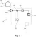
- FIG. 2 illustrates another exemplary water supply system 100.
- Components of the water supply system 100 already illustrated in and explained with respect to Figure 1 will not be described again, for the sake of brevity. Same components are indicated by the same reference numerals.
- the water supply system 100 of Figure 2 includes a multiport water supply valve 135 configured to activate and deactivate the water supply from the pressurisation unit 120 to one or more of the plurality of water consumers 131, 132.
- the multiport water supply valve 135 e.g., a shuttle valve
- the multiport water supply valve 135 can be configured to distribute water from the pressurisation unit 120 to one or more pipe or duct branches leading to the water consumers 131, 132.
- the control unit 180 can be further configured to control the multiport water supply valve 135 depending on the consumer signal.
- the consumer signal indicates a water supply of a respective water consumer 131, 132 (or of more than one water consumer 131, 132), so that the control unit 180 can open the multiport water supply valve 135 with respect to the corresponding pipe or duct branch(es).
- This water supply system 100 allows omission of individual water consumer valves 133, 134, which reduces the overall complexity of the water supply system.
- the control of the water supply system 100 via control unit 180 may be performed in the same manner as explained with respect to Figure 1 , with the exception of controlling the multiport water supply valve 135 instead of the individual water consumer valves 133, 134.
- FIG 3 illustrates a portion of a further exemplary water supply system 100.
- Components of the water supply system 100 already illustrated in and explained with respect to Figure 1 or 2 will not be described again, for the sake of brevity. Same components are indicated by the same reference numerals.
- the further exemplary water supply system 100 is equipped with a further (second) pressurisation unit 122 connected to the water supply tank 110 in series with the (first) pressurisation unit 120.
- the (first) pressurisation unit 120 can be the one illustrated and described with respect to Figures 1 and 2 .
- an additional (second) pressurisation unit 122 is provided. This allows increasing the pressure of the water supply downstream of the first and second pressurisation units 120, 122.
- the second pressurisation unit 122 can likewise be controlled by the control unit 180, particularly the flow rate and/or pressure of the further pressurisation unit 122 can be individually or simultaneously be controlled with the (first) pressurisation unit 120 by the control unit 180.
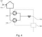
- FIG 4 illustrates a portion of a further exemplary water supply system 100.
- Components of the water supply system 100 already illustrated in and explained with respect to Figure 1 or 2 will not be described again, for the sake of brevity. Same components are indicated by the same reference numerals.
- the further exemplary water supply system 100 is equipped with a further (second) pressurisation unit 123 connected to the water supply tank 110 parallel to the (first) pressurisation unit 120.
- the (first) pressurisation unit 120 can be the one illustrated and described with respect to Figures 1 and 2 .
- an additional (second) pressurisation unit 123 is provided. This allows increasing a flow rate of the water supply downstream of the first and second pressurisation units 120, 123.
- the second pressurisation unit 123 can likewise be controlled by the control unit, particularly the flow rate at/or pressure of the further pressurisation unit 123 can be individually or simultaneously be controlled with the (first) pressurisation unit 120 by the control unit 180.
- the respective control unit 180 can be configured to adjust the water supply to the water consumers 131, 132 not only by adaptation of the electrical input of the (first) pressurisation unit 120, but also by activation of a specific number of pressurisation units 120, 122, 123.
- the (second) pressurisation unit 122, 123 can be controlled by adaptation of an electrical input (voltage, current, frequency, pulse width modulation, etc.).
- Figures 3 and 4 illustrate a multiport water supply valve 135, it is to be understood that the (second) pressurisation unit 122, 123 can likewise be employed in the water supply system 100 of Figure 1 comprising water consumer valves 133, 134.
- pressurisation units 120, 122, 123 can be arranged in a water supply system 100, wherein one pair of pressurisation units 120, 122 is connected in series to one another, while another pair of pressurisation units 120, 123 is connected parallel to one another.
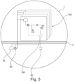
- FIG. 5 schematically illustrates an aircraft 1 comprising at least one water supply system 100.
- This at least one water supply system 100 can be any of the water supply systems 100a-d illustrated and described with respect to one of Figures 1 to 4 .
- the aircraft 1 is equipped with a central water supply system including a central water tank 50 and central water conveying device 60. Furthermore, the aircraft 1 can have a plurality of monuments or other structures requiring water supply, such as one or more galleys, one or more lavatories, one or more washrooms, etc.. Each of these monuments or structures includes a respective water supply system 100a-d having the water consumers required for the monument or structure.
- the aircraft can comprise a central control device 80 connected to the control unit 180 of each of the water supply systems 100.
- the central control device 80 can be configured to output a central water supply signal.
- This central water supply signal can indicate one or more of a water level of the central water tank 50, a remaining flight time, a high water consumption time, cabin occupancy, usage frequency of the water consumers, the general standard time (UTC), and a venting or rinsing phase of the at least one water supply system 100.
- the control unit 180 of the at least one water supply system 100 can further be configured to receive the central water supply signal from the central control device 80 and to control the flow rate of the respective pressurisation unit 120 depending on the central water supply signal. This may include that the central water supply signal overwrites any predefined settings in the control unit 180 and/or that the control unit 180 adjusts any predefined setting in the control unit 180 based on the central water supply signal. For example, during start-up and/or venting/rinsing phase of the central water system and/or one or more of the plurality of water supply systems 100, the respective control unit 180 can operate the respective pressurisation units 120 to fulfil the start-up requirements and/or venting/rinsing air or water supply.
- the central control device 80 may be coupled to a cabin attendant panel or include a cabin attendant interface, which allows a cabin attendant to perform certain water supply settings.
- a water boost function may be initiated via the central control device 80. For instance, on long haul flights the faucet flow rate (at a wash basin 131) can be increased for washing periods (e.g. after food and beverage service, after sleeping phases, etc.) while it is reduced for the remaining time. This allows a controllable water-saving feature.
- the central control device 80 can be connected to an aircraft data network, so that all required information (e.g., flight phase, lavatory data, galley data, etc.) can be retrieved via the aircraft data network.
- the central control device 80 may be programmed to automatically control the central water conveying device 60 as well as the at least one water supply system 100, in order to reduce a workload of the cabin attendants.
- the water supply provided by the central water conveying device 60 as well as the respective pressurisation units 120 of the water supply systems 100 can be reduced, in order to save water.
Landscapes
- Engineering & Computer Science (AREA)
- Aviation & Aerospace Engineering (AREA)
- Physics & Mathematics (AREA)
- General Physics & Mathematics (AREA)
- Automation & Control Theory (AREA)
- Fluid Mechanics (AREA)
- Health & Medical Sciences (AREA)
- Life Sciences & Earth Sciences (AREA)
- Hydrology & Water Resources (AREA)
- Public Health (AREA)
- Water Supply & Treatment (AREA)
- Sanitary Device For Flush Toilet (AREA)
Abstract
The present disclosure relates to a water supply system (100) for an aircraft (1) that comprises a water supply tank (110), a plurality of water consumers (131, 132), a pressurisation unit (120) configured to convey water from the water supply tank (110) to the plurality of water consumers (131, 132), a plurality of water consumer supply units (141, 142), each of the plurality of water consumer supply units (141, 142) being configured to control water supply from the pressurisation unit (120) to one of the plurality of water consumers (131, 132); and a control unit (180). Each of the plurality of water consumer supply units (141, 142) is configured to output a consumer signal indicating a water supply of the respective water consumer (131, 132), wherein the control unit (180) is configured to receive the consumer signal of the plurality of water consumer supply units (141, 142) and to control a flow rate and/or pressure of the pressurisation unit (120) depending on the consumer signal.
Description
- The present disclosure generally relates to an adjustable water supply system for an aircraft and an aircraft having such water supply system. Particularly, the present disclosure relates to a water supply system capable of controlling a pressurisation unit conveying water from a water supply tank to a plurality of water consumers, and an aircraft having such water supply system.
- A conventional water supply system for aircrafts includes a central water tank and water conveying device supplying water to all water consumers in the aircraft. Such water consumers include lavatory monuments (e.g. having a faucet and a toilet) and galleys (e.g. having a faucet, a hot water dispenser, food preparation devices, etc.).
- The water conveying device is designed to provide a sufficient amount of water to all water consumers, and provide the necessary overall water pressure. As a mere example, a rinsing nozzle for a toilet usually requires a higher water pressure than a faucet. The water conveying device, however, is designed to provide the maximum water amount and pressure in the aircraft. In addition, at times of a frequent use of water, such as during washing times during a flight, a plurality of water consumers require a sufficient water supply. The central water conveying device, hence, is further designed for this maximum supply (i.e., a maximum amount or flow rate).
- Thus, a conventional water supply system for an aircraft is easily overdesigned, which may lead to an increased energy consumption.
- It is therefore an object of the present disclosure to provide an improved water supply system, particularly saving energy and overall weight.
- This object is solved by the present invention as defined in the independent claims. Preferred embodiments are defined by the dependent claims.
- According to a first aspect to better understand the present disclosure, a water supply system for an aircraft region comprises a water supply tank, a plurality of water consumers, a pressurisation unit configured to convey water from the water supply tank to the plurality of water consumers, and a plurality of water consumer supply units. The plurality of water consumers are connected to the water supply tank via the pressurisation unit with corresponding ducts or pipes. Such ducts or pipes are designed to duct water under the pressure induced by the pressurisation unit. The pressurisation unit can be a pump, such as a unidirectional or reverse water pump, a micro pump a positive displacement pump (e.g., a membrane pump, gear pump, impeller pump) or non-positive displacement pump (e.g., a centrifugal pump) or the like. The pressurisation unit can be operated in a forward as well as a reverse mode.
- The aircraft region comprises a dedicated number of water consumers. For example, an aircraft region can be a monument, such as a lavatory monument or a galley, or can be a group of monuments, particularly arranged spatially close to one another. This allows sharing the water supply tank between the water consumers in this aircraft region.
- Each of the plurality of water consumer supply units is configured to control water supply from the pressurisation unit to one of the plurality of water consumers. In other words, the water consumer supply units initiate water supply to the water consumers. For example, each of the plurality of water consumer supply units is configured to output a consumer signal indicating a water supply of the respective water consumer. Thus, each water consumer supply unit can trigger a water supply to a respective water consumer.
- Furthermore, the water supply system comprises a control unit that is configured to receive the consumer signal of the plurality of water consumer supply units and to control a flow rate and/or pressure of the pressurisation unit depending on the consumer signal. Thus, the water supply system provides (conveys) water to a water consumer, only if the consumer signal is output by the respective water consumer supply unit.
- As a mere example, an energy supply for the pressurisation unit can be adjusted. A low-energy supply to the pressurisation unit can lead to a small flow rate and/or low pressure of the water provided by the pressurisation unit, while a high energy supply to the pressurisation unit can lead to a high flow rate and/or pressure of the water. For instance, a pump speed can be adjusted by the control unit.
- Since the control unit can be made aware of the water consumer (through the output consumer signal), the water supply can be adjusted in view of or adapted to the water consumer. Particularly, the flow rate and/or pressure output by the pressurisation unit can be adjusted or preset with respect to the water consumer requesting a water supply. As a mere example, if a faucet is activated, the pressurisation unit may provide a lower flow rate than in case of a rinsing nozzle of a toilet bowl being activated. Likewise, if the water consumer is a galley insert, such as a coffeemaker, the control unit can be configured to control the pressurisation unit with a constant and sufficiently high pressure and flow rate required for the coffeemaker.
- Compared to conventional water supply systems, the energy used by the pressurisation pump can be significantly reduced, since not the maximum pressure and flow rate is to be provided. For example, in conventional water supply systems faucets have been equipped with aerators and/or pressure regulators, in order to avoid spilling due to too high pressure water output.
- With the disclosed water supply system such aerators and/or pressure regulators can be omitted, since the pressurisation unit can now be controlled based on the consumer signal. This further reduces maintenance efforts, which usually come with the checking and changing of aerators and/or pressure regulators.
- In addition, the water supply system of the present disclosure does not only save energy, but further reduces sound emissions of the pressurisation unit, as it does not operate at its maximum level all the time.
- In an implementation variant, each of the plurality of water consumer supply units can be coupled to or comprise a water consumer valve configured to activate and deactivate the water supply from the pressurisation unit to the respective water consumer. The water consumer supply unit can, for example, control the water consumer valve. For example, the water consumer supply unit can include a sensor and/or switch configured to open and close (activate and deactivate) the water consumer valve. In addition, the sensor and/or switch can further be configured to set an opening degree of the water consumer valve, in order to adjust the water supply (amount and/or flow rate and/or pressure).
- Alternatively or additionally, each of the plurality of water consumer supply units is configured to output the consumer signal further indicating the activation or deactivation of the water supply and/or an opening degree of the water consumer valve. Thus, the control unit can further be configured to control a flow rate of the pressurisation unit depending on the consumer signal, i.e. depending on the activation or deactivation of the water supply, and/or depending on the opening degree of the water consumer valve. Thus, a further optimisation of the water supply can be achieved by correspondingly controlling the pressurisation unit (i.e. the flow rate and/or pressure provided by pressurisation unit).
- Further alternatively or additionally, the water consumer supply unit, particularly a sensor and/or switch of the water consumer supply unit, can generate the consumer signal indicating the activation and deactivation of the water supply and/or a desired opening degree of the water consumer valve. The control unit can then be further configured to control the water consumer valve in accordance with the consumer signal. For example, the control unit can open the water consumer valve up to a desired opening degree and operate the pressurisation unit at a flow rate and/or pressure corresponding to the opening degree (including fully open, which equals an open water consumer valve) or close the water consumer valve. For instance, the control unit can be connected to the water consumer valve and transmit a signal to the water consumer valve indicating the opening, opening degree or closing of the water consumer valve. As a mere example, the water consumer valve may include an actuator (e.g., a motor or the like) configured to steplessly open and close the water consumer valve.
- Furthermore, if a water consumer supply unit associated with a faucet outputs a consumer signal, the control unit can control the water consumer valve to provide a fluid connection between the pressurisation unit and the faucet, and to further control the flow rate of the pressurisation unit in correspondence with the needs of the faucet. Likewise, more than one water consumer supply unit can output a consumer signal, such as a rinsing switch for a toilet and a switch or sensor of a faucet. In this case, the control unit can control the respective water consumer valve to provide a fluid connection between the pressurisation unit and the rinsing nozzle of the toilet as well as the faucet, and further to control the flow rate of the pressurisation unit in correspondence with the combined needs of the rinsing nozzle and the faucet.
- In another implementation variant, the water supply system can further comprise a multiport water supply valve configured to activate and deactivate the water supply from the pressurisation unit to one or more of the plurality of water consumers. Such multiport water supply valve can be configured to provide a fluid connection between a supply line from the pressurisation unit to one or more supply lines to the water consumers. As a mere example, the multiport water supply valve can be implemented as a shuttle valve.
- In any case, the control unit can be further configured to control the multiport water supply valve depending on the consumer signal. Thus, the control unit can control the multiport water supply valve to allow a fluid connection between the pressurisation unit and one or more of the plurality of water consumers depending on the consumer signal. As a mere example, if a water consumer supply unit associated with a faucet outputs a consumer signal, the control unit can control the multiport water supply valve to provide a fluid connection between the pressurisation unit and the faucet, and to further control the flow rate of the pressurisation unit in correspondence with the needs of the faucet. Likewise, more than one water consumer supply unit can output a consumer signal, such as a rinsing switch for a toilet and a switch or sensor of a faucet. In this case, the control unit can control the multiport water supply valve to provide a fluid connection between the pressurisation unit and the rinsing nozzle of the toilet as well as the faucet, and further to control the flow rate of the pressurisation unit in correspondence with the combined needs of the rinsing nozzle and the faucet.
- In a further implementation variant, the control unit can be configured to control the flow rate and/or pressure of the pressurisation unit to a first flow rate and/or a first pressure for a first water consumer of the plurality of water consumers, and to a second flow rate and/or second pressure for a second water consumer of the plurality of water consumers, wherein the second flow rate and/or pressure is larger than the first flow rate and/or pressure. Likewise, the control unit can be configured to control the flow rate and/or pressure of the pressurisation unit to a third flow rate and/or third pressure, wherein the third flow rate and/or pressure is larger than the first and second flow rate and/or pressure. Thus, different flow rates and/or pressures of the pressurisation unit can be achieved depending on the needs of the one or more water consumers requesting a water supply through the respective, associated water consumer supply unit. This allows using only the energy by the pressurisation unit required for the present needs (the present requested water supply).
- Moreover, the control unit can optionally be further configured to control the first and second flow rate and/or pressure of the pressurisation unit depending on one or more water consumer parameters. Such consumer parameters can include the type of water consumer (such as faucet, toilet, galley insert, or the like), a water supply request at the water consumer (such as high, medium or low flow rate request), or a priority level of the water consumer (such as high priority to a coffeemaker requesting continuous flow rate and pressure, or medium to high priority to a toilet in business class, etc.). The consumer parameter may further include a filling level of the water supply tank, although the water supply tank is not a consumer. For instance, a load filling level may be an indication for the control unit to reduce the first and/or second flow rate and/water pressure.
- In yet a further implementation variant, the control unit can be configured to control the flow rate of the pressurisation unit depending on a type of the water consumer and/or a location of the water consumer in the aircraft, for which the consumer signal is output. Thus, an optimisation of the flow rate can be achieved. As a mere example, some types of water consumers, such as a food or beverage maker, require a constant flow rate and/or pressure of water, in order to properly function. Otherwise, food or beverage may not have the desired quality. This can be taken into account by the control unit.
- In an implementation variant, the type of the water consumer can include a faucet for a wash basin, a rinse nozzle for a toilet, and a water consuming galley insert in a galley. Such water consuming galley insert can be a coffeemaker, hot water dispenser, steam oven, galley faucet or the like. The control unit receiving a consumer signal indicating such type of water consumer can have a predefined flow rate and/or pressure of water to be supplied to such consumer type. As indicated above, some water consumer types are more sensitive to fluctuating water flow rate and/or pressure, so that the control unit controls the pressurisation unit accordingly, i.e. provides a constant flow rate and/or pressure of water via the pressurisation unit. As a mere example, if such a sensitive water consumer requests a water supply, while a further consumer signal is received from another but less sensitive water consumer, the control unit may either increase the flow rate and/or pressure of water provided by the pressurisation unit, and/or postpone or delay the activation of the less sensitive water consumer until the sensitive water consumer has finished its operation (does not require a dedicated water supply).
- Likewise, the location of the water consumer can include a front section, middle section and rear section of the aircraft, a first or business class or economy class installed in the aircraft, lavatory monument, and/or a galley. For instance, the location of the water consumer may result in different priorities given to the associated water consumers. The control unit can, hence, control the pressurisation unit in order to provide a flow rate and/or pressure of water at each water consumer based on the priority given to the respective water consumer.
- Furthermore, if the consumer signal indicates a location in a premium class, such as first or business class, the control unit may be configured to control the pressurisation unit to provide a higher flow rate and/or pressure of water for all water consumers at this "premium location". This avoids the usually negative personal impression, if the water is supplied with a low flow rate and/or pressure. Likewise, in economy class, more passengers may require water during washing times, so that the control unit can further be configured to control the pressurisation unit to provide a higher pressure to compensate an increased overall water consumption.
- In another implementation variant, the water supply system can further comprise a further pressurisation unit configured to convey water from the water supply tank to the plurality of water consumers. The further pressurisation unit (also referred to as a second pressurisation unit) is provided in addition to the (first) pressurisation unit described so far.
- For instance, the further pressurisation unit can be connected to the water supply tank in parallel or series with the pressurisation unit. A parallel arrangement of the (first and second) pressurisation units allows a higher flow rate, if both pressurisation units are operating. Multiple pressurisation units provided in series, on the other hand, allow increasing the pressure of water supplied by the pressurisation units.
- Furthermore, the control unit can be further configured to control a flow rate and/or pressure of the further pressurisation unit individually or simultaneously with the pressurisation unit. Particularly, operating the (first and second) pressurisation units simultaneously, allows increasing the flow rate and/or pressure of the water supply. Operating the (first or second) pressurisation units individually, allows a flow rate and/or pressure of the water supply of a desired value.
- Alternatively or additionally, the further pressurisation unit can have a different throughput (water supplying power) than the (first) pressurisation unit. Thus, operation of one of the (first or second) pressurisation units allows providing a predefined flow rate and/or pressure of the water supply.
- Further alternatively or additionally, the control unit can be configured to control the flow rate and/or pressure of the water conveyed to the plurality of water consumers by activating or deactivating the pressurisation unit and/or the further pressurisation unit. Thus, a simple control of the supplied water can be achieved by switching on and off one or more pressurisation units. As a mere example, one or more power levels of the respective pressurisation unit may be predefined. The control unit can then activate or deactivate the respective pressurisation unit at one of the one or more power levels. This allows achieving any flow rate and/or pressure output by the plurality of pressurisation units.
- In yet another implementation variant, the water supply system can further comprise a refill valve coupled to a central water supply system and configured to fill water into the water supply tank. As a mere example, the refill valve is fluidly connected to a water pipe of the central water supply system. Opening the refill valve allows refilling the water supply tank. The operation of the refill valve can be controlled by the control unit. Particularly, since the control unit controls the water supply based on the consumer signal(s), the control unit may evaluate or gauge or predict a water level in the water supply tank based on the current water consumption. This allows refilling water into the water supply tank corresponding to the current and/or future needs.
- Furthermore, the control unit can be configured to control the refill valve, in order to refill the water supply tank. At the same time, the control unit can send a corresponding signal to the central water supply system, in order to inform the central water supply system of the demand of refill water.
- According to a second aspect to better understand the present disclosure, an aircraft comprises at least one water supply system of the first aspect or one of its variants and/or examples.
- In an implementation variant, the aircraft can comprise a central water tank, a central water conveying device configured to convey water to the at least one water supply system, and a central control device connected to the control unit and configured to output a central water supply signal. The central control device can be a cabin assignment module operated by a flight attendant for setting certain conditions regarding the cabin of the aircraft. As a mere example, a flight attendant may set the cabin of the aircraft into a sleeping phase mode, where the majority of passengers will sleep. During this time the light of the cabin is usually switched off. The control unit of the at least one water supply system can receive a corresponding information signal from the central control device, so that the respective pressurisation unit is operated in a low flow rate and/or pressure mode, in order to avoid loud sound emission from the pressurisation unit. As a mere example, the information signal from the central control device may be interpreted by the control unit to operate the pressurisation unit at 90%, 80%, 70% or even 60% for all predefined flow rate and/or pressure values.
- It is to be understood that the central control device may operate fully automatically, i.e. without flight attendant involvement.
- Furthermore, the central control device can be connected to the control unit via a data network or data link provided in the aircraft to communicate data and information between different central control units, flight attendant panels and/or pilot controls.
- Moreover, the control unit of the at least one water supply system can be further configured to receive the central water supply signal from the central control device and to control the flow rate and/or pressure of the pressurisation unit depending on the central water supply signal. Thus, while the control unit of each of the at least one water supply system can have predefined flow rates and/or pressure values for the respective water consumers, such values may be adapted or overwritten depending on the central water supply signal.
- In a further implementation variant, the central water supply signal can indicate one or more of a water level of the central water tank, a remaining flight time, a high water consumption time, cabin occupancy, usage frequency of the water consumers, a flight phase, a cabin scenario (such as sleeping, wake up, washing, catering cycle, etc.), a filling level of the water supply tank of the at least one water supply system, an integral over filling levels of all water supply tanks, a filling level of the water supply tank of a prioritised one of the at least one water supply system, the general standard time (UTC), and a venting or rinsing phase of the at least one water supply system. A low water level of the central water tank may result in the control unit of each of the at least one water supply system to reduce the flow rate and/or pressure of water supply provided by the pressurisation unit. Thus, water can be saved and a situation where the central water tank is empty may be avoided. Likewise, if the remaining flight time is shorter than a predefined threshold, a water saving phase may be started, wherein the control unit of each of the at least one water supply system generally reduces a flow rate and/or pressure of water supply provided by the respective pressurisation unit. Here, exceptions may again be made depending on the location of the water supply system (e.g., first or economy class) and/or depending on the type of water consumer (e.g., a galley insert).
- Furthermore, the central water supply signal can further indicate one or more of time dependent effects of the water supply system and, particularly, the pressurisation unit of the at least one water supply system and/or the central water conveying device. For instance, hydraulic restrictions may occur over time (e.g., scaling of an aerator or nozzle, a biofilm deposit, a particle deposit, or the like). Likewise, the pump performance may be reduced over time due to ageing effects. In such case, the central water supply signal received by the control unit of the at least one water supply system allows the control unit to adapt the operation of the pressurisation unit to compensate for such differences.
- The central control device can further be configured to control the central water conveying device in accordance with a "soft start", i.e. a speed of the conveying device in accordance with a ramp curve. Likewise, the central water conveying device may be operated in reverse mode, for example, during a drainage of the central water tank and corresponding water system of the aircraft. Alternatively or additionally, the central control device may be configured to control the central water conveying device depending on a reduced performance of the central water conveying device (e.g., due to ageing).
- In an implementation variant, the aircraft can comprise one or more monuments. The at least one water supply system can be installed in one of such monuments. A monument can be a lavatory monument having a faucet and a toilet, and/or a galley having a faucet, a hot water dispenser, a food preparation device, or the like.
- In another implementation variant, the central control device can further be configured to control the central water conveying device to convey water with a flow rate and/or pressure depending on the number of water consumers of the at least one water supply system currently running (i.e., running at the same time), the total number of water consumers currently running, an integral of a water level of each water supply tank in the at least one water supply system, and/or if one or more water supply tanks have reached a critically low water level, such as below 20% or below 10%, or even an empty tank. This allows keeping a minimum water level buffered in the water supply tank of the at least one water supply system.
- Moreover, the central control device can be further configured to control the central water conveying device to convey water with a flow rate and/or pressure depending on one or more water consumer parameters. Such consumer parameters, which can be derived by the central control device from the control unit of the at least one water supply system, can include the type of water consumer (such as faucet, toilet, galley insert, or the like) currently requesting water, a water supply request at the water consumer (such as high, medium or low flow rate request), or a priority level of the water consumer (such as high priority to a coffeemaker requesting continuous flow rate and pressure, or medium to high priority to a toilet in business class, etc.).
- In addition, the central control device can be further configured to control the central water conveying device on the basis of a filling level of the water supply tank of the at least one water supply system. This can include a prioritisation of one or more water supply tanks in case of a plurality of water supply systems. For instance, the water supply tank or tanks with the lowest fill level may receive water via the refill valve. This may include sending a corresponding signal to the control unit of the at least one water supply system identifying the priority of the respective water supply system, so that the associated control unit refills the water supply tank or waits with the refill process.
- Furthermore, it can even be contemplated that a video surveillance unit may determine whether there is a queue in front of one of the lavatories. Alternatively or additionally, statistical data may be provided by a corresponding computing device of the aircraft. Based on such data, one of the at least one water supply system may be prioritised.
- A further option for the central control device to control the central water conveying device can be the number of refill valves currently opened at the water supply systems. In other words, if more than one water supply system is currently refilling the associated water supply tank, an increased flow rate and/or pressure can be provided by the central water conveying device.
- The present disclosure is not restricted to the aspects and variants in the described form and order. Specifically, the description of aspects and variants is not to be understood as a specific limiting grouping of features. It is to be understood that the present disclosure also covers combinations of the aspects and variants. Thus, each variant or optional feature can be combined with any other aspect, variant, optional feature or even combinations thereof.
- In the following, the present disclosure will further be described with reference to exemplary implementations illustrated in the figures, in which:
- Figure 1
- schematically illustrates a plurality of water supply systems;
- Figure 2
- schematically illustrates an exemplary water supply system;
- Figure 3
- schematically illustrates another exemplary water supply system;
- Figure 4
- schematically illustrates a further exemplary water supply system; and
- Figure 5
- schematically illustrates an aircraft comprising a plurality of water supply systems.
- In the following description, for purposes of explanation and not limitation, specific details are set forth in order to provide a thorough understanding of the present disclosure. It will be apparent to one skilled in the art that the present disclosure may be practiced in other implementations that depart from these specific details.
-
Figure 1 schematically illustrates a plurality ofwater supply systems 100a-d, wherein onewater supply system 100a is illustrated in more detail. For instance, eachwater supply system 100a-d may be associated with a particular water consumer, group of water consumers and/or monument in an aircraft.Water supply system 100a, for example, can be associated with a lavatory monument.Water supply systems 100b-d can respectively be associated with a further lavatory monument, a galley, a washroom including a shower, a water dispenser niche and the like. The components described with respect to thewater supply system 100a, or at least a subgroup of these components, may also be included in the otherwater supply systems 100b-d. - For example, the
water supply system 100 comprises awater supply tank 110 storing or buffering a certain amount of water associated with thewater supply system 100. As a mere example, as a galley may require more water in a particular time period during which food and beverages are provided, thewater supply tank 110 may be designed larger than in awater supply system 100a for a lavatory, but smaller than in awater supply system 100 for a washroom including a shower (not illustrated). - The
water supply tank 110 may be filled with water from a central water supply system, for example, from acentral water tank 50 and by awater conveying device 60 and corresponding ducts and pipes distributing the water from thewater conveying device 60 to the differentwater supply systems 100. For instance, by opening arefill valve 105 coupled to the central water supply system, thewater supply tank 110 can be filled with water. It is to be understood that a fill level reached by the filling of thewater supply tank 110 may depend on different parameters, including the priority given to the water supply system (galley, business class lavatory, etc.) and/or a filling level of thecentral water tank 50. As a mere example, if thecentral water tank 50 has a fill level of 20% or less, low prioritywater supply systems 100 may not be re-filled or may only be filled with less water. In this regard, thecentral water tank 50 may include a water level sensor (not explicitly illustrated). - The
water supply system 100 further comprises a plurality of water consumers, such as awashbasin 131 or faucet and atoilet bowl 132 or rinsing nozzle (not individually illustrated). Each of the plurality ofwater consumers water supply tank 110 via a respective pipe or duct as illustrated. - The
water supply system 100 includes apressurisation unit 120 configured to convey water from thewater supply tank 110 to the plurality ofwater consumers pressurisation unit 120, a distributing piping or ducting may be provided, having pipe or duct branches to each of the plurality ofwater consumers - Furthermore, a plurality of water
consumer supply units water supply system 100. Each waterconsumer supply unit pressurisation unit 120 to a respective one of the plurality ofwater consumers respective water consumer consumer supply unit 141 is associated with awater consumer 131, here an exemplary washbasin, usually having a faucet (not individually illustrated). If a passenger requires water from the faucet, a sensor or switch is activated by the passenger, in order to start a water supply. This sensor or switch can be integrated into the waterconsumer supply unit 141. - The
water supply system 100 further comprises acontrol unit 180 that is electrically and/or electronically coupled (illustrated as dashed lines) to at least the plurality of waterconsumer supply units consumer supply unit 141 outputs the consumer signal, for example, due to activation of a faucet (sensor or switch) by the passenger, the control unit is configured to receive the consumer signal and to control a flow rate and/or pressure of thepressurisation unit 120 depending on the consumer signal. Thus, thepressurisation unit 120 can be operated only when the consumer signal is received by thecontrol unit 180, and thepressurisation unit 120 can be operated in an optimised manner for the activated water consumer(s) 131, 132. It is to be understood that thepressurisation unit 120 and/or the waterconsumer supply units central control device 80, e.g., connected to thecontrol unit 180 via an aircraft data network. Such remote control may be performed during a disinfection of the water supply system, maintenance, tests or the like. - Moreover, the
control unit 180 may have stored a predefined water supply, i.e. may have stored which consumer receives a specific water supply (flow rate and/or pressure). This predefined water supply may include a (hardcoded) default value for the flow rate and/or pressure required by the respective water consumer. In addition, the predefined water supply may be retrieved from a general data and/or information centre (not illustrated). It is to be understood that the predefined water supply (values) can be programmed into thecontrol unit 180 any time, for example, by a flight attendant or a more general aircraft system. - On the other hand, the
control unit 180 can be further configured to control the flow rate and/or pressure of thepressurisation unit 120 to be a first flow rate and/or pressure for a first water consumer (e.g., washbasin 131), and to a second flow rate and/or pressure for a second water consumer (e.g. rinsing nozzle of toilet bowl 132). Since each water consumer can be related to a different predefined water supply (flow rate and/or pressure), the first and second flow rate and/or pressure can be different. As a mere example, thesecond water consumer 132 may require a higher flow rate and/or higher water pressure for rinsing and cleaning the toilet bowl. Thus, thecontrol unit 180 may provide a higher second flow rate and/or pressure for thesecond water consumer 131 by operating thepressurisation unit 120 at a higher level. - For instance, the power of the
pressurisation unit 120 can be adjusted by thecontrol unit 180 according to the predefined water supply linking the water consumer arrangement with an associated water supply rate. The power control of thepressurisation unit 120 can include adaptation of an electrical input (voltage, current, frequency, pulse width modulation, etc.) to thepressurisation unit 120. - It is to be understood that the
control unit 180 can be further configured to control the flow rate and/or pressure of thepressurisation unit 120 in accordance with dependencies on other parameters, such as which water consumers are currently running (at the same time) or the like. Furthermore, thecontrol unit 180 can be further configured to control the flow rate and/or pressure of thepressurisation unit 120 depending on a filling level of thewater supply tank 110. For instance, depending on the filling level, a flow rate could be reduced, such as below 30% or below 20% filling level. -
Figure 1 illustrates a plurality of exemplarywater consumer valves pressurisation unit 120. Eachwater consumer valve pressurisation unit 120 to therespective water consumer water consumer valves consumer supply unit consumer supply unit closed valve 133, 134) and/or an opening degree of thewater consumer valve control unit 180 to operate thepressurisation unit 120 in accordance with thewater consumer valve - Alternatively, each
water consumer valve control unit 180 depending on the consumer signal received from the waterconsumer supply unit control unit 180 can control water supply through thepressurisation unit 120 in interaction with the opening and closing of the water consumer valve(s) 133, 134. - In any case, the passenger will not notice any difference of the actual water supply compared to conventional water supply systems. Nevertheless, the
water supply system 100 of the present disclosure will lead to less sound emission, i.e. a quieter water supply, as well as less energy consumption. - Moreover, the
water supply system 100 may further comprise anoptional water filter 150, e.g., upstream of the faucet for thewashbasin 131. Thecontrol unit 180 may hold a predefined first water supply (flow rate and/or pressure) for the faucet for thewashbasin 131 as well as a predefined second water supply for the combination ofwater filter 150 and faucet for thewashbasin 131. The second water supply may be larger (e.g., higher flow rate and/or higher pressure) in order to compensate any pressure drop in a specific water consumer arrangement, such as thewater filter 150 plus faucet for thewashbasin 131. Thecontrol unit 180 may further be provided with information about a type ofwater filter 150, in order to compensate any pressure drop specific to the type ofwater filter 150. - The same applies to the type of
water consumer washbasin 131 and rinsing nozzle for atoilet bowl 132, thewater consumers water supply system 100b-d), such as a coffeemaker, hot water dispenser, steam oven, etc.. -
Figure 2 illustrates another exemplarywater supply system 100. Components of thewater supply system 100 already illustrated in and explained with respect toFigure 1 will not be described again, for the sake of brevity. Same components are indicated by the same reference numerals. - The
water supply system 100 ofFigure 2 includes a multiportwater supply valve 135 configured to activate and deactivate the water supply from thepressurisation unit 120 to one or more of the plurality ofwater consumers pressurisation unit 120 to one or more pipe or duct branches leading to thewater consumers - The
control unit 180 can be further configured to control the multiportwater supply valve 135 depending on the consumer signal. In other words, the consumer signal, as explained above, indicates a water supply of arespective water consumer 131, 132 (or of more than onewater consumer 131, 132), so that thecontrol unit 180 can open the multiportwater supply valve 135 with respect to the corresponding pipe or duct branch(es). - This
water supply system 100 allows omission of individualwater consumer valves water supply system 100 viacontrol unit 180 may be performed in the same manner as explained with respect toFigure 1 , with the exception of controlling the multiportwater supply valve 135 instead of the individualwater consumer valves -
Figure 3 illustrates a portion of a further exemplarywater supply system 100. Components of thewater supply system 100 already illustrated in and explained with respect toFigure 1 or2 will not be described again, for the sake of brevity. Same components are indicated by the same reference numerals. - The further exemplary
water supply system 100 is equipped with a further (second)pressurisation unit 122 connected to thewater supply tank 110 in series with the (first)pressurisation unit 120. The (first)pressurisation unit 120 can be the one illustrated and described with respect toFigures 1 and2 . Thus, an additional (second)pressurisation unit 122 is provided. This allows increasing the pressure of the water supply downstream of the first andsecond pressurisation units second pressurisation unit 122 can likewise be controlled by thecontrol unit 180, particularly the flow rate and/or pressure of thefurther pressurisation unit 122 can be individually or simultaneously be controlled with the (first)pressurisation unit 120 by thecontrol unit 180. -
Figure 4 illustrates a portion of a further exemplarywater supply system 100. Components of thewater supply system 100 already illustrated in and explained with respect toFigure 1 or2 will not be described again, for the sake of brevity. Same components are indicated by the same reference numerals. - The further exemplary
water supply system 100 is equipped with a further (second)pressurisation unit 123 connected to thewater supply tank 110 parallel to the (first)pressurisation unit 120. The (first)pressurisation unit 120 can be the one illustrated and described with respect toFigures 1 and2 . Thus, an additional (second)pressurisation unit 123 is provided. This allows increasing a flow rate of the water supply downstream of the first andsecond pressurisation units second pressurisation unit 123 can likewise be controlled by the control unit, particularly the flow rate at/or pressure of thefurther pressurisation unit 123 can be individually or simultaneously be controlled with the (first)pressurisation unit 120 by thecontrol unit 180. - Thus, in view of each of the
water supply systems 100 ofFigures 3 and4 , therespective control unit 180 can be configured to adjust the water supply to thewater consumers pressurisation unit 120, but also by activation of a specific number ofpressurisation units pressurisation unit - Although
Figures 3 and4 illustrate a multiportwater supply valve 135, it is to be understood that the (second)pressurisation unit water supply system 100 ofFigure 1 comprisingwater consumer valves - It is further to be understood that a combination of the
water supply systems 100 ofFigures 3 and4 is likewise possible. Thus, at least threepressurisation units water supply system 100, wherein one pair ofpressurisation units pressurisation units -
Figure 5 schematically illustrates an aircraft 1 comprising at least onewater supply system 100. This at least onewater supply system 100 can be any of thewater supply systems 100a-d illustrated and described with respect to one ofFigures 1 to 4 . - The aircraft 1 is equipped with a central water supply system including a
central water tank 50 and centralwater conveying device 60. Furthermore, the aircraft 1 can have a plurality of monuments or other structures requiring water supply, such as one or more galleys, one or more lavatories, one or more washrooms, etc.. Each of these monuments or structures includes a respectivewater supply system 100a-d having the water consumers required for the monument or structure. - In addition, the aircraft can comprise a
central control device 80 connected to thecontrol unit 180 of each of thewater supply systems 100. Thecentral control device 80 can be configured to output a central water supply signal. This central water supply signal can indicate one or more of a water level of thecentral water tank 50, a remaining flight time, a high water consumption time, cabin occupancy, usage frequency of the water consumers, the general standard time (UTC), and a venting or rinsing phase of the at least onewater supply system 100. - The
control unit 180 of the at least onewater supply system 100 can further be configured to receive the central water supply signal from thecentral control device 80 and to control the flow rate of therespective pressurisation unit 120 depending on the central water supply signal. This may include that the central water supply signal overwrites any predefined settings in thecontrol unit 180 and/or that thecontrol unit 180 adjusts any predefined setting in thecontrol unit 180 based on the central water supply signal. For example, during start-up and/or venting/rinsing phase of the central water system and/or one or more of the plurality ofwater supply systems 100, therespective control unit 180 can operate therespective pressurisation units 120 to fulfil the start-up requirements and/or venting/rinsing air or water supply. - Moreover, the
central control device 80 may be coupled to a cabin attendant panel or include a cabin attendant interface, which allows a cabin attendant to perform certain water supply settings. As a mere example, a water boost function may be initiated via thecentral control device 80. For instance, on long haul flights the faucet flow rate (at a wash basin 131) can be increased for washing periods (e.g. after food and beverage service, after sleeping phases, etc.) while it is reduced for the remaining time. This allows a controllable water-saving feature. As a mere example, thecentral control device 80 can be connected to an aircraft data network, so that all required information (e.g., flight phase, lavatory data, galley data, etc.) can be retrieved via the aircraft data network. In addition, thecentral control device 80 may be programmed to automatically control the centralwater conveying device 60 as well as the at least onewater supply system 100, in order to reduce a workload of the cabin attendants. - Furthermore, depending on a water level in the
central water tank 50 and/or a remaining flight time, the water supply provided by the centralwater conveying device 60 as well as therespective pressurisation units 120 of thewater supply systems 100 can be reduced, in order to save water. - It is believed that the advantages of the technique presented herein will be fully understood from the foregoing description, and it will be apparent that various changes may be made in the form, constructions and arrangement of the exemplary aspects thereof without departing from the scope of the disclosure or without sacrificing all of its advantageous effects. Because the technique presented herein can be varied in many ways, it will be recognized that the disclosure should be limited only by the scope of the claims that follow.
Claims (13)
- A water supply system (100) for an aircraft region (100), comprising:a water supply tank (110);a plurality of water consumers (131, 132);a pressurisation unit (120) configured to convey water from the water supply tank (110) to the plurality of water consumers (131, 132);a plurality of water consumer supply units (141, 142), each of the plurality of water consumer supply units (141, 142) being configured to control water supply from the pressurisation unit (120) to one of the plurality of water consumers (131, 132); anda control unit (180),characterised in thateach of the plurality of water consumer supply units (141, 142) is configured to output a consumer signal indicating a water supply of the respective water consumer (131, 132), andthe control unit (180) is configured to receive the consumer signal of the plurality of water consumer supply units (141, 142) and to control a flow rate and/or pressure of the pressurisation unit (120) depending on the consumer signal.
- The water supply system (100) of claim 1, wherein each of the plurality of water consumer supply units (141, 142) is coupled to or comprises a water consumer valve (133, 134) configured to activate and deactivate the water supply from the pressurisation unit (120) to the respective water consumer (131, 132), and/or
wherein each of the plurality of water consumer supply units (141, 142) is configured to output the consumer signal further indicating the activation or deactivation of the water supply and/or an opening degree of the water consumer valve (133, 134). - The water supply system (100) of claim 1, further comprising:a multiport water supply valve (135) configured to activate and deactivate the water supply from the pressurisation unit (120) to one or more of the plurality of water consumers (131, 132),wherein the control unit (180) is further configured to control the multiport water supply valve (135) depending on the consumer signal.
- The water supply system (100) of one of claims 1 to 3, wherein the control unit (180) is configured to control the flow rate and/or pressure of the pressurisation unit (120) to a first flow rate and/or pressure for a first water consumer (131) of the plurality of water consumers, and to a second flow rate and/or pressure for a second water consumer (132) of the plurality of water consumers, wherein the second flow rate and/or pressure is larger than the first flow rate and/or pressure,
wherein, preferably, the control unit (180) is further configured to control the first and/or second flow rate and/or pressure of the pressurisation unit (120) depending on one or more water consumer parameters. - The water supply system (100) of one of claims 1 to 4, wherein the control unit (180) is configured to control the flow rate and/or pressure of the pressurisation unit (120) depending on a type of the water consumer (131, 132) and/or a location of the water consumer (131, 132) in the aircraft (1), for which the consumer signal is output.
- The water supply system (100) of claim 5, wherein the type of the water consumer (131, 132) includes a faucet for a wash basin (131), a rinse nozzle for a toilet (132), and a water consuming galley insert in a galley, and/or
wherein the location of the water consumer (131, 132) includes a front section, middle section and rear section of the aircraft (1), a first or business class or economy class installed in the aircraft (1), and/or a galley. - The water supply system (100) of one of claims 1 to 6, further comprising:a further pressurisation unit (122, 123) configured to convey water from the water supply tank (110) to the plurality of water consumers (131, 132),wherein the further pressurisation unit (122, 123) is connected to the water supply tank (110) in parallel or series with the pressurisation unit (120), and/orwherein the control unit (180) is further configured to control a flow rate and/or pressure of the further pressurisation unit (122, 123) individually or simultaneously with the pressurisation unit (120), and/orwherein the control unit (180) is further configured to control the flow rate and/or pressure of the water conveyed to the plurality of water consumers (131, 132) by activating or deactivating the pressurisation unit (120) and/or the further pressurisation unit (122, 123), preferably at one or more predefined power levels of the respective pressurisation unit (120, 122, 123).
- The water supply system (100) of one of claims 1 to 7, further comprising:
a refill valve (105) coupled to a central water supply system and configured to fill water into the water supply tank (110). - An aircraft (1), comprising:
at least one water supply system (100) of one of claims 1 to 8. - The aircraft (1) of claim 9, further comprising:a central water tank (50);a central water conveying device (60) configured to convey water to the at least one water supply system (100); anda central control device (80) connected to the control unit (180) and configured to output a central water supply signal,wherein the control unit (180) of the at least one water supply system (100) is further configured to receive the central water supply signal from the central control device (80) and to control the flow rate and/or pressure of the pressurisation unit (120) depending on the central water supply signal.
- The aircraft (1) of claim 10, wherein the central water supply signal indicates one or more of a water level of the central water tank (50), a remaining flight time, a high water consumption time, cabin occupancy, usage frequency of the water consumers (131, 132) and a venting or rinsing phase of the at least one water supply system (100).
- The aircraft (1) of claim 10 or 11, wherein the at least one water supply system (100) is installed in a monument, preferably a lavatory monument (100a) having a faucet (131) and a toilet (132), and/or a galley having a faucet (131), a hot water dispenser, and/or a food preparation devices.
- The aircraft (1) of claim 12, wherein the central control device (80) is further configured to control the central water conveying device (60) to convey water with a flow rate and/or pressure depending on the number of water consumers of the at least one water supply system (100) currently running, the total number of water consumers currently running, and/or an integral of a water level of each water supply tank (110) in the at least one water supply system (100).
Priority Applications (2)
| Application Number | Priority Date | Filing Date | Title |
|---|---|---|---|
| EP23181036.7A EP4480818A1 (en) | 2023-06-22 | 2023-06-22 | Adjustable water supply system and aircraft equipped with a water supply system |
| US18/749,695 US20240425198A1 (en) | 2023-06-22 | 2024-06-21 | Adjustable water supply system and aircraft equipped with a water supply system |
Applications Claiming Priority (1)
| Application Number | Priority Date | Filing Date | Title |
|---|---|---|---|
| EP23181036.7A EP4480818A1 (en) | 2023-06-22 | 2023-06-22 | Adjustable water supply system and aircraft equipped with a water supply system |
Publications (1)
| Publication Number | Publication Date |
|---|---|
| EP4480818A1 true EP4480818A1 (en) | 2024-12-25 |
Family
ID=86942286
Family Applications (1)
| Application Number | Title | Priority Date | Filing Date |
|---|---|---|---|
| EP23181036.7A Pending EP4480818A1 (en) | 2023-06-22 | 2023-06-22 | Adjustable water supply system and aircraft equipped with a water supply system |
Country Status (2)
| Country | Link |
|---|---|
| US (1) | US20240425198A1 (en) |
| EP (1) | EP4480818A1 (en) |
Citations (3)
| Publication number | Priority date | Publication date | Assignee | Title |
|---|---|---|---|---|
| US20180238765A1 (en) * | 2017-02-22 | 2018-08-23 | Max H. GRAMESPACHER | Method and system for water metering and unusual water flow detection |
| US20220342431A1 (en) * | 2021-04-23 | 2022-10-27 | Airbus Operations Gmbh | Water supply system for an aircraft |
| US20220404228A1 (en) * | 2021-06-18 | 2022-12-22 | The Boeing Company | Water leak detection systems and methods for an internal cabin of an aircraft |
Family Cites Families (5)
| Publication number | Priority date | Publication date | Assignee | Title |
|---|---|---|---|---|
| CA2686836C (en) * | 2008-12-01 | 2017-04-11 | International Water-Guard Industries, Inc. | Water distribution system with dual use water treatment unit |
| JP7003885B2 (en) * | 2018-09-18 | 2022-02-04 | 横浜ゴム株式会社 | Aircraft hot water supply system |
| US20210031923A1 (en) * | 2019-07-30 | 2021-02-04 | B/E Aerospace, Inc. | Aircraft Galley Plumbing System |
| US11726505B2 (en) * | 2020-01-21 | 2023-08-15 | Mag Aerospace Industries, Llc | Water control system for aircraft |
| US12626196B2 (en) * | 2023-03-27 | 2026-05-12 | B/E Aerospace, Inc. | Central cabin control systems and methods |
-
2023
- 2023-06-22 EP EP23181036.7A patent/EP4480818A1/en active Pending
-
2024
- 2024-06-21 US US18/749,695 patent/US20240425198A1/en active Pending
Patent Citations (3)
| Publication number | Priority date | Publication date | Assignee | Title |
|---|---|---|---|---|
| US20180238765A1 (en) * | 2017-02-22 | 2018-08-23 | Max H. GRAMESPACHER | Method and system for water metering and unusual water flow detection |
| US20220342431A1 (en) * | 2021-04-23 | 2022-10-27 | Airbus Operations Gmbh | Water supply system for an aircraft |
| US20220404228A1 (en) * | 2021-06-18 | 2022-12-22 | The Boeing Company | Water leak detection systems and methods for an internal cabin of an aircraft |
Also Published As
| Publication number | Publication date |
|---|---|
| US20240425198A1 (en) | 2024-12-26 |
Similar Documents
| Publication | Publication Date | Title |
|---|---|---|
| US12105541B2 (en) | Water supply system for an aircraft | |
| US8074933B2 (en) | Aircraft graywater ejection system | |
| US11459106B2 (en) | Aircraft water supply system | |
| US10059454B2 (en) | Aircraft galley plumbing system | |
| US20240425198A1 (en) | Adjustable water supply system and aircraft equipped with a water supply system | |
| US20190365936A1 (en) | Method For Disinfecting A Water System Of An Aircraft | |
| US20190203456A1 (en) | Method of Controlling a Vacuum Waste System and a Vacuum Waste System | |
| US12503232B2 (en) | Method for draining a local water distribution system | |
| EP2999629B1 (en) | Grey water interface for high flow applications in vacuum systems | |
| US20210404162A1 (en) | Vacuum-assisted toilet systems and methods of using the same | |
| EP4361040B1 (en) | Water supply system with cross-feed link and aircraft having a water supply system | |
| JP5839761B1 (en) | Faucet for aircraft water supply unit | |
| EP4480819A1 (en) | High pressure water supply system and aircraft equipped with such system | |
| WO2017040541A1 (en) | Cruciform water distribution valve for aircraft galley plumbing system | |
| US20250128817A1 (en) | Method and system for operating a pump and valve in a water supply system of an aircraft | |
| US20260117499A1 (en) | Faucet for an aircraft cabin | |
| CN120863878A (en) | aircraft sections and aircraft | |
| EP4650275A1 (en) | Multifunctional water supply system with buffer tank for potable water delivery | |
| JP2023034493A (en) | Washing water tank device and flush toilet bowl device comprising the same | |
| JP2006257666A (en) | Sanitary washing device |
Legal Events
| Date | Code | Title | Description |
|---|---|---|---|
| PUAI | Public reference made under article 153(3) epc to a published international application that has entered the european phase |
Free format text: ORIGINAL CODE: 0009012 |
|
| STAA | Information on the status of an ep patent application or granted ep patent |
Free format text: STATUS: THE APPLICATION HAS BEEN PUBLISHED |
|
| AK | Designated contracting states |
Kind code of ref document: A1 Designated state(s): AL AT BE BG CH CY CZ DE DK EE ES FI FR GB GR HR HU IE IS IT LI LT LU LV MC ME MK MT NL NO PL PT RO RS SE SI SK SM TR |
|
| STAA | Information on the status of an ep patent application or granted ep patent |
Free format text: STATUS: REQUEST FOR EXAMINATION WAS MADE |
|
| 17P | Request for examination filed |
Effective date: 20250625 |
|
| STAA | Information on the status of an ep patent application or granted ep patent |
Free format text: STATUS: EXAMINATION IS IN PROGRESS |