EP4480816A2 - Cargo restraint system with individually retractable restraints - Google Patents
Cargo restraint system with individually retractable restraints Download PDFInfo
- Publication number
- EP4480816A2 EP4480816A2 EP24208490.3A EP24208490A EP4480816A2 EP 4480816 A2 EP4480816 A2 EP 4480816A2 EP 24208490 A EP24208490 A EP 24208490A EP 4480816 A2 EP4480816 A2 EP 4480816A2
- Authority
- EP
- European Patent Office
- Prior art keywords
- plunger
- restraint
- head
- shroud
- lever
- Prior art date
- Legal status (The legal status is an assumption and is not a legal conclusion. Google has not performed a legal analysis and makes no representation as to the accuracy of the status listed.)
- Pending
Links
Images







Classifications
-
- B—PERFORMING OPERATIONS; TRANSPORTING
- B64—AIRCRAFT; AVIATION; COSMONAUTICS
- B64D—EQUIPMENT FOR FITTING IN OR TO AIRCRAFT; FLIGHT SUITS; PARACHUTES; ARRANGEMENT OR MOUNTING OF POWER PLANTS OR PROPULSION TRANSMISSIONS IN AIRCRAFT
- B64D9/00—Equipment for handling freight; Equipment for facilitating passenger embarkation or the like
- B64D9/003—Devices for retaining pallets or freight containers
-
- B—PERFORMING OPERATIONS; TRANSPORTING
- B60—VEHICLES IN GENERAL
- B60P—VEHICLES ADAPTED FOR LOAD TRANSPORTATION OR TO TRANSPORT, TO CARRY, OR TO COMPRISE SPECIAL LOADS OR OBJECTS
- B60P7/00—Securing or covering of load on vehicles
- B60P7/06—Securing of load
- B60P7/08—Securing to the vehicle floor or sides
- B60P7/0807—Attachment points
-
- B—PERFORMING OPERATIONS; TRANSPORTING
- B60—VEHICLES IN GENERAL
- B60P—VEHICLES ADAPTED FOR LOAD TRANSPORTATION OR TO TRANSPORT, TO CARRY, OR TO COMPRISE SPECIAL LOADS OR OBJECTS
- B60P7/00—Securing or covering of load on vehicles
- B60P7/06—Securing of load
- B60P7/08—Securing to the vehicle floor or sides
- B60P7/0892—Securing to the vehicle floor or sides by preventing lateral movement of the load, e.g. using stop blocks
-
- B—PERFORMING OPERATIONS; TRANSPORTING
- B60—VEHICLES IN GENERAL
- B60P—VEHICLES ADAPTED FOR LOAD TRANSPORTATION OR TO TRANSPORT, TO CARRY, OR TO COMPRISE SPECIAL LOADS OR OBJECTS
- B60P7/00—Securing or covering of load on vehicles
- B60P7/06—Securing of load
- B60P7/13—Securing freight containers or forwarding containers on vehicles
-
- B—PERFORMING OPERATIONS; TRANSPORTING
- B64—AIRCRAFT; AVIATION; COSMONAUTICS
- B64D—EQUIPMENT FOR FITTING IN OR TO AIRCRAFT; FLIGHT SUITS; PARACHUTES; ARRANGEMENT OR MOUNTING OF POWER PLANTS OR PROPULSION TRANSMISSIONS IN AIRCRAFT
- B64D9/00—Equipment for handling freight; Equipment for facilitating passenger embarkation or the like
- B64D2009/006—Rollers or drives for pallets of freight containers, e.g. PDU
Definitions
- the present disclosure is directed to cargo restraint systems and, more particularly, to a cargo restraint system capable of actuating restraints in groups and individually.
- cargo bays designed to receive cargo.
- cargo bays include cargo loading systems that include rollers located on a floor of the cargo bay to provide conveyance for moving a unit load device (ULD) or other cargo through the cargo bay.
- ULD unit load device
- ULDs have pockets along the sides of the ULD. Restraints may be located in the pockets to provide longitudinal and/or lateral restraint. Such restraint reduces the likelihood of cargo shifting relative to the cargo bay during taxi, takeoff, flight, and landing.
- Some current restraint actuation systems gang (or group) together multiple restraints such that restraints can be actuated (e.g., raised or stowed) from a single point and/or with a single action. Raising or stowing all of the ganged restraints limit the number of available cargo load configurations. In this regard, additional cargo load configurations would be possible if individual restraints, within the ganged restraints, could be selectively rotated to a stowed position.
- the restraint may comprise a head defining a plunger channel and a plunger including a plunger rod and a plunger lever.
- the plunger rod may be located, at least, partially in the plunger channel.
- a plunger torsion spring may be configured to apply a first biasing load to the plunger lever.
- a compression spring may be configured to bias a first end of the plunger away from an upper surface of the head.
- a drive cap may be located around the first end of the plunger rod.
- a shroud may be located proximate the first end of the plunger rod. The shroud may define a plunger opening configured to receive the first end of the plunger rod.
- the shroud may include a protrusion extending radially outward from an outer circumferential surface of the shroud.
- the protrusion may be configured to contact the drive cap.
- the head may include a first lever interference surface configured to contact a first lever surface of the plunger lever, when the first end of the plunger rod is located in the plunger opening of the shroud.
- an end of the plunger lever may be configured to rotate above the upper surface of the head in response to the first end of the plunger rod being located radially outward of an outer circumferential surface of the shroud.
- the cargo restraint system may comprise a first restraint configured to rotate about an axis, a second restraint configured to rotate about the axis, and an actuator assembly configured to simultaneously rotate the first restraint and the second restraint between a raised position and a stowed position.
- the first restraint may include a head configured to rotate about the axis, and a plunger configured to translate between an engaged state and a disengaged state. In the engaged state the head may be rotationally coupled to the actuator assembly, and in the disengaged state the head of the first restraint may rotate independently of the second restraint and the actuator assembly.
- the plunger may include a plunger rod and a plunger lever.
- the plunger rod may be configured to translate in a radial direction relative to the axis.
- the plunger lever may be configured to rotate about a pin located through the plunger rod.
- the first restraint may further include a plunger torsion spring configured to apply a first biasing load to the plunger lever, and a compression spring configured to bias a first end of the plunger rod toward the axis.
- the head of the first restraint may include a first lever interference surface configured to contact a first lever surface of the plunger when the plunger is in the engaged state.
- the actuator assembly may comprise an actuator shaft configured to rotate about the axis.
- the first restraint and the second restraint may be located about the actuator shaft.
- the first restraint may further include a shroud located radially between the actuator shaft and the head of the first restraint.
- the shroud may define a plunger opening configured to receive the plunger. In the engaged state, the plunger is located in the plunger opening. In the disengaged state, the plunger is located radially outward of an outer circumferential surface of the shroud.
- the first restraint may further include a drive cap coupled to the head.
- the shroud may include a protrusion extending radially outward from the outer circumferential surface of the shroud.
- the protrusion may be configured to contact the drive cap.
- a key may be located in a key opening defined by the shroud and in a key channel defined by the actuator shaft.
- the cargo loading system may comprise a panel defining an orifice, a restraint located in the orifice, and an actuator shaft configured to rotate the restraint between a raised position and a stowed position.
- the restraint may comprise a head configured to rotate about an axis and a plunger configured to translate between an engaged state and a disengaged state. In the engaged state, the head is rotationally coupled to the actuator shaft. In the disengaged state, the head may rotate independently of the actuator shaft.
- the plunger may include a plunger rod and a plunger lever.
- the restraint may further include a plunger torsion spring configured to apply a biasing load to the plunger lever and a compression spring configured to bias a first end of the plunger rod away from an upper surface of the head.
- the plunger lever in the disengaged state, may be configured to contact an underside surface of the panel when the restraint is in the stowed position.
- the restraint may further include a shroud located radially between the actuator shaft and the head of the first restraint.
- the shroud may define a plunger opening configured to receive the plunger. In the engaged state, the plunger may be located in the plunger opening, and in the disengaged state, the plunger may be located radially outward of an outer circumferential surface of the shroud.
- the restraint may further include a drive cap coupled to the head.
- the shroud may include a protrusion extending radially outward from the outer circumferential surface of the shroud. The protrusion may be configured to contact the drive cap.
- the present disclosure provides a restraint for an aircraft cargo restraint system that is individually retractable.
- the restraint may be rotated (e.g., using any appropriate motion or combination of motions) from a raised (or deployed) position to a stowed position, while the other restraints in the system remain in the raised position.
- the restraint system includes an actuation assembly configured to translate and/or rotate a first group of the restraints.
- Each of the restraints in the first group of restraints includes a plunger. The plunger may be translated between an engaged state and a disengaged state.
- the restraint When a restraint's plunger is in the engaged state, the restraint is rotationally coupled to its respective actuation assembly, such that rotation of the actuation assembly causes rotation of the restraint.
- the restraint When a restraint's plunger is in the disengaged state, the restraint may be actuated (e.g., rotated) independently from the other restraints coupled to the actuation assembly. Allowing the restraints to be actuated as a group or independently from one another allows for both control of groups from a single actuation, while increasing the number of available restraining configurations throughout the cargo deck.
- FIG. 1 illustrates an aircraft 20 with cargo 22 being loadable through a loading door 24 of the aircraft 20.
- Cargo 22 e.g., a ULD, pallet, or the like
- FIG. 2 illustrates cargo deck 26.
- An X-Y-Z axis is shown in various drawings to illustrate various orientations of components.
- cargo deck 26 includes a cargo deck floor 30, which may be formed by one or more panels 32 that are coupled to various structural components of aircraft 20 (e.g., to beams, floors, etc.).
- cargo deck 26 includes a cargo restraint system 50.
- cargo restraint system 50 may be installed along cargo deck 26.
- Cargo deck 26 may also include a cargo loading system 60 comprising a plurality of freely rotating conveyance rollers and/or powder drive units (PDUs) mounted in the cargo deck 26 to define the conveyance plane. Cargo loaded onto the aircraft cargo deck 26 can be moved throughout the cargo deck 26 using the cargo loading system 60.
- PDUs powder drive units
- Cargo restraint system 50 may be used to restrain cargo (e.g., unit load devices (ULDs)) within/relative to the cargo deck 26.
- the cargo restraint system 50 may include a plurality of first restraints 102, one or more secondary restraints 104, and a plurality of third restraints 106.
- the first restraints 102 may be referred to as X-restraints as they may restrict cargo from translating in the X (or longitudinal) direction.
- the secondary restraints 104 may be referred to as Z-restraints as they may restrict cargo from translating in the Z (or vertical) direction.
- the third restraints 106 may be referred to as YZ-restraints as they may restrict translation of cargo in the Z direction and the Y (or lateral) direction.
- the restraints 102, 104, 106 may be used to restrain cargo in any other directions (e.g., the first restraints 102 may restrain cargo in the Y direction, secondary restraints may restrain cargo in the X direction, etc.).
- the restraint system 50 may include an actuation assembly 110.
- a control region 112 of actuation assembly 110 may be located, for example, proximate loading door 24, a forward end of the aircraft, and/or at any other location that may be readily accessible to crew responsible for loading cargo into cargo deck 26.
- various components of actuation assembly 110 may be located under panels 32.
- Actuation assembly 110 is configured to control the actuation of the first restraints 102.
- actuation assembly 110 may be employed to simultaneously rotate first restraints 102 between a raised position and a stowed position.
- actuation assembly 110 may also control actuation of the second restraints 104 and/or the third restraints 106.
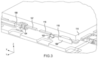
- FIG. 3 illustrates how the various restraints of restraint system 50 may restrain a ULD 114.
- the first restraint 102 may rest between tab 116 and tab 118 of the ULD 114, restricting movement of the ULD 114 in the X direction.
- the second restraint 104 may rest above and between tab 107 and tab 109 of the ULD 114, restricting movement of the ULD 114 in the Z direction and the X direction.
- the third restraint 106 may rest adjacent and above the tab 118 of the ULD 114, restricting movement of the ULD 114 in the Y direction and the Z direction.
- first restraint 102 may be actuated between a raised position (as shown in FIG. 4A ) and a stowed position (as shown in FIG. 4B ).
- First restraint 102 may include a head (or restraint body) 120, which may be both raised and stowed. In the raised position, head 120 extends above the cargo deck floor 30. Stated differently, in the raised position, at least, a portion of head 120 is located above an upper surface 36 of the panel 32. In the stowed position, head 120 may fit within an orifice 122 formed in the cargo deck floor 30.
- panel 32 may define an orifice 122 configured to receive head 120.
- a first surface 124 of head 120 may be substantially flush (e.g., ⁇ 15° from flush) and/or planar with upper surface 36 of the panel 32.
- first restraint 102 is illustrated in the raised position.
- panel 32 is removed to illustrate components of cargo restraint system 50 that may be located under upper surface 36 of panel 32.
- First restraint 102 may be raised into (e.g., located within) a pocket 117 of ULD 114.
- Pocket 117 may be defined by a flange 119 located about a perimeter of ULD 114.
- Flange 119 may form one or more of tabs 107, 109, 116, 118 in FIG. 3 .
- a mount 140 ( FIG. 5B ) may be coupled to panel 32 via fasteners 142.
- an actuator shaft 150 may be located through, and may extend through, mount 140 and head 120. Stated differently, mount 140 and head 120 may be located on, and/or mounted on, actuator shaft 150. Mount 140 may be a stationary structure. Head 120 and actuator shaft 150 may rotate relative to mount 140. Actuator shaft 150 rotates about an axis A-A'.
- first restraint 102 may include one or more head torsion spring(s) 160.
- head torsion spring 160 may be configured to bias head 120 toward the raised position. Stated differently, head torsion spring 160 may be configured to bias head 120 in a first circumferential direction C1 ( FIG. 6 ) about axis A-A'. In various embodiments, head torsion spring 160 may be configured to bias head 120 toward the stowed position. In various embodiments, the head torsion spring may be eliminated.
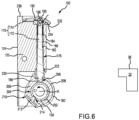
- first restraint 102 includes a plunger 170 ( FIG. 6 ), which may engage actuator shaft 150, such that rotation of actuation shaft is transferred to head 120. Stated differently, when the plunger 170 is in an engaged state, head 120 rotates with actuator shaft 150.
- first restraint 102 includes a plunger 170.
- first restraint 102 is in the raised position and plunger 170 is in an engaged state.
- Plunger 170 includes a plunger rod 172 and a plunger lever 174.
- Plunger rod 172 is configured to translate radially (i.e., perpendicular to axis A-A'). In this regard, plunger rod 172 translates toward and away from actuator shaft 150 and axis A-A'.
- plunger rod 172 may be located in a plunger channel 176 defined by head 120.
- a compression spring 180 may be located about plunger rod 172.
- Compression spring 180 may be compressed between a spring interference surface 182 of plunger rod 172 and a bushing 184 located about plunger rod 172.
- bushing 184 may be eliminated and compression spring 180 may be compressed between spring interference surface 182 of plunger rod 172 and a second spring interference surface formed by head 120.
- Compression spring 180 biases a first end 186 of plunger rod 172 in the radially inward direction (i.e., toward actuator shaft 150 and axis A-A').
- a pin 188 may be located through plunger rod 172 and plunger lever 174. Pin 188 may be located proximate a second end 190 of plunger rod 172. Second end 190 is opposite first end 186. Plunger lever 174 may rotate about pin 188. A plunger torsion spring 192 may be located about pin 188 and may apply a biasing load to plunger lever 174. Plunger torsion spring 192 may bias plunger lever 174 in a first circumferential direction C2 about pin 188.
- a shroud 200 may be located about actuator shaft 150. Stated differently, an inner circumferential surface 202 of shroud 200 may define a shaft channel 204 configured to receive actuator shaft 150. In accordance with various embodiments, a plunger opening 206 is formed in the outer circumferential surface 208 of shroud 200. Stated differently, shroud 200 defines plunger opening 206. Plunger opening 206 is configured to receive first end 186 of plunger rod 172. Locating plunger rod 172 in plunger opening 206 creates an interference between plunger rod 172 and shroud 200, such that plunger rod 172 is prevented from translating relative to shroud 200.
- shroud 200 defines a key opening (e.g., a bore) 210 configured to receive a key 212.
- Actuator shaft 150 may define a key channel 214.
- Key 212 may be located through key opening 210 and in key channel 214, in response to radially aligning key opening 210 and key channel 214. Locating key 212 in key opening 210 and key channel 214 rotationally couples shroud 200 to actuator shaft 150, such that rotation of actuator shaft 150 about axis A-A' causes shroud 200 to rotate about axis A-A'.
- Shroud 200 includes a protrusion 220.
- Protrusion 220 extends radially outward from outer circumferential surface 208 of shroud 200.
- a drive cap 222 may be located around first end 186 of plunger rod 172, and between plunger rod 172 and head 120. Drive cap 222 may be coupled to head 120.
- protrusion 220 When plunger 170 is an engaged state (i.e., when plunger rod 172 is located in plunger opening 206), protrusion 220 may be located proximate drive cap 222 and/or may abut drive cap 222.
- Rotation of actuator shaft 150 about axis A-A' causes shroud 200 to rotate in the same direction about axis A-A' as actuator shaft 150 due to key 212 being located in and contacting both actuator shaft 150 and shroud 200.
- rotation of shroud 200 in a second circumferential direction C4 causes head 120 to rotate in the second circumferential direction C4 about axis A-A' due to the contact between protrusion 220 and drive cap 222.
- plunger torsion spring 192 is configured to bias first lever surface 232 toward first lever interference surface 234.
- first lever surface 232 and first lever interference surface 234 blocks, or prevents, further rotation of plunger lever 174 in the first circumferential direction C2 about pin 188 (i.e., the inference overcomes the biasing load being applied by plunger torsion spring 192).
- plunger lever 174 may be located radially inward of an upper surface 236 of head 120.
- a distance between plunger lever 174 and axis A-A' may be less than a distance between upper surface 236 and axis A-A'.
- Upper surface 236 may be approximately perpendicular to first surface 124 and side surfaces 132 ( FIG. 5B ).
- the spring constant of compression spring 180 is selected (e.g., is great enough) to overcome the biasing load applied by plunger torsion spring 192.
- first restraint 102 taken along line 6-6 in FIG. 5B , is illustrated, with first restraint 102 in the raised position and plunger 170 in a disengaged state.
- a load L1 is applied to plunger lever 174, thereby causing plunger lever 174 to rotate in a second circumferential C3 about pin 188 (e.g., in a direction opposite the biasing force applied by plunger torsion spring 192).
- the load L1 along with an interference between an end 240 of plunger lever 174 and a second lever interference surface 242 of head 120, forces pin 188, second end 190 of plunger rod 172, and first lever surface 232 away from first lever interference surface 234 of head 120 and axis A-A'.
- the translation of plunger rod 172 away from axis A-A' causes first end 186 of plunger rod 172 to translate out of plunger opening 206.
- the translation of plunger rod 172 away from axis A-A' also compresses compression spring 180 between spring interference surface 182 and bushing 184.
- first restraint 102 taken along line 6-6 in FIG. 5B , is illustrated, with plunger 170 in the disengaged state and first restraint 102 beginning to rotate toward the stowed position.
- head 120 can rotate about shroud 200.
- first end 186 of plunger rod 172 radially outward of outer circumferential surface 208 of shroud 200 removes the interference between shroud 200 and plunger rod 172, thereby allowing first end 186 of plunger rod 172 to translate circumferentially about axis A-A' and along the outer circumferential surface 208 of shroud 200.
- Shroud 200 does not rotate with head 120 due, at least in part, to the contact between key 212 and actuator shaft 150.
- head 120 With plunger 170 in the disengaged state, head 120 can be rotated in a second circumferential direction C4 about shroud 200, actuator shaft 150, and axis A-A' (e.g., toward the stowed position) in response to a load L2 greater than the biasing force of head torsion spring 160 being applied to head 120.
- outer circumferential surface 208 of shroud 200 blocks first end 186 of plunger rod 172 from translating radially inward (i.e., toward axis A-A'), thereby maintaining the distance between pin 188 and first lever interference surface 234 of head 120 and between second end 190 of plunger rod 172 and first lever interference surface 234.
- Plunger lever 174 may rotate about pin 188 until first lever surface 232 contacts head 120 (e.g., until plunger lever 174 contacts first lever interference surface 234). In the disengaged state, end 240 of plunger lever 174 may be located above upper surface 236 of head 120. Stated differently, a distance between end 240 of plunger lever 174 and axis A-A' may be greater than the distance between upper surface 236 of head 120 and axis A-A', when plunger 170 is in the disengaged state.
- first restraint 102 taken along line 6-6 in FIG. 5B , is illustrated, with plunger 170 in the disengaged state and first restraint 102 in the stowed position.
- plunger torsion spring 192 forces plunger lever 174 to rotate in the first circumferential direction C2 about pin 188, thereby forcing end 240 of plunger lever 174 to translate past (e.g., above) upper surface 236 of head 120.
- Load L2 FIG.
- head torsion spring 160 may bias head 120 in the first circumferential direction C 1 about axis A-A'.
- the biasing force of head torsion spring 160 forces end 240 of plunger lever 274 toward an underside surface 262 of panel 32.
- Underside surface 262 of panel is oriented away from upper surface 36 of panel.
- the contact between end 240 of plunger lever 174 and underside surface 262 of panel 32 maintains head 120 in the stowed position. Stated differently, the interference between plunger lever 174 and underside surface 262 prevents first restraint 102 from rotating to the raised position.
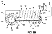
- first restraint 102 taken along line 6-6 in FIG. 5B , is illustrated, with the plunger in the disengaged state and prior to first restraint 102 being rotated from the stowed state toward the raised state.
- plunger 170 is translated to the engaged position, thereby rotationally coupling head 120 to shroud 200 and actuator shaft 150.
- actuator shaft 150 is rotated about axis A-A', thereby causing shroud 200 to rotate about axis A-A'.
- protrusion 220 of shroud 200 brings protrusion 220 of shroud 200 into contact with drive cap 222.
- Protrusion 220 and drive cap 222 are configured such that plunger opening 206 is radially aligned with the first end 186 of plunger rod 172 when protrusion 220 contacts drive cap 222, however, the frictional force between underside surface 262 and plunger lever 174 prevents plunger rod 172 from translating into plunger opening 206.
- the contact between protrusion 220 and drive cap 222 may force head 120 to rotate in the second circumferential direction C4 about axis A-A' (i.e., away from the raised position and in the direction opposite the direction of the biasing load applied by head torsion spring 160).
- the rotation of head 120 in the second circumferential direction C4 about axis A-A' forces end 240 of plunger lever 174 away from underside surface 262 of panel 32.
- first restraint 102 taken along line 6-6 in FIG. 5B , is illustrated, with plunger 170 in the engaged state and with first restraint 102 in position for the first restraint 102 to be rotated from the stowed position toward the raised position.
- removing the frictional force between plunger lever 174 and underside surface 262 of panel 32, along with the biasing force applied by compression spring 180 and the alignment of first end 186 of plunger rod 172 with plunger opening 206 causes first end 186 of plunger rod 172 to translate radially inward, toward axis A-A' and into plunger opening 206.
- plunger rod 172 translates second end 190 of plunger rod 172 and pin 188 toward first lever interference surface 234, thereby forcing first lever surface 232 into contact with first lever interference surface 234.
- the contact between first lever interference surface 234 and first lever surface 232 forces end 240 of plunger lever 174 toward second lever interference surface 242, thereby locating end 240 of plunger lever 174 radially inward of upper surface 136 of head 120.
- head 120 may be rotated in the first circumferential direction C1 about axis A-A' and into the raised position.
- FIGs. 4A-8C describe details of first restraint 102, it is further contemplated and understood that secondary restraints 104 and/or third restraints 106 in FIGs. 2 and 3 may include the features and functionalities described herein with reference to first restraint 102.
- secondary restraints 104 and/or third restraints 106 may include a plunger, similar to plunger 170, and rotation of the secondary restraints 104 and/or third restraints 106 between a raised position and a stowed position may be controlled by actuation assembly 110 when the plungers are in an engaged state, and by rotating the restraints independently of one another when the plungers are in a disengaged state.
- references to "one embodiment”, “an embodiment”, “an example embodiment”, etc. indicate that the embodiment described may include a particular feature, structure, or characteristic, but every embodiment may not necessarily include the particular feature, structure, or characteristic. Moreover, such phrases are not necessarily referring to the same embodiment. Further, when a particular feature, structure, or characteristic is described in connection with an embodiment, it is submitted that it is within the knowledge of one skilled in the art to affect such feature, structure, or characteristic in connection with other embodiments whether or not explicitly described. After reading the description, it will be apparent to one skilled in the relevant art(s) how to implement the disclosure in alternative embodiments.
Landscapes
- Engineering & Computer Science (AREA)
- Transportation (AREA)
- Mechanical Engineering (AREA)
- Aviation & Aerospace Engineering (AREA)
- Superstructure Of Vehicle (AREA)
- Handcart (AREA)
- Pivots And Pivotal Connections (AREA)
- Seats For Vehicles (AREA)
- Transmission Devices (AREA)
Abstract
Description
- The present disclosure is directed to cargo restraint systems and, more particularly, to a cargo restraint system capable of actuating restraints in groups and individually.
- Many aircraft have at least one cargo bay designed to receive cargo. Such cargo bays include cargo loading systems that include rollers located on a floor of the cargo bay to provide conveyance for moving a unit load device (ULD) or other cargo through the cargo bay. After cargo has been loaded into the cargo bay, it may be desirable to restrain the cargo. Some ULDs have pockets along the sides of the ULD. Restraints may be located in the pockets to provide longitudinal and/or lateral restraint. Such restraint reduces the likelihood of cargo shifting relative to the cargo bay during taxi, takeoff, flight, and landing. Some current restraint actuation systems gang (or group) together multiple restraints such that restraints can be actuated (e.g., raised or stowed) from a single point and/or with a single action. Raising or stowing all of the ganged restraints limit the number of available cargo load configurations. In this regard, additional cargo load configurations would be possible if individual restraints, within the ganged restraints, could be selectively rotated to a stowed position.
- According to an aspect, a restraint for use with a cargo loading system is disclosed herein. In accordance with various embodiments, the restraint may comprise a head defining a plunger channel and a plunger including a plunger rod and a plunger lever. The plunger rod may be located, at least, partially in the plunger channel. A plunger torsion spring may be configured to apply a first biasing load to the plunger lever. A compression spring may be configured to bias a first end of the plunger away from an upper surface of the head.
- In various embodiments, a drive cap may be located around the first end of the plunger rod. In various embodiments, a shroud may be located proximate the first end of the plunger rod. The shroud may define a plunger opening configured to receive the first end of the plunger rod.
- In various embodiments, the shroud may include a protrusion extending radially outward from an outer circumferential surface of the shroud. In various embodiments, the protrusion may be configured to contact the drive cap.
- In various embodiments, the head may include a first lever interference surface configured to contact a first lever surface of the plunger lever, when the first end of the plunger rod is located in the plunger opening of the shroud. In various embodiments, an end of the plunger lever may be configured to rotate above the upper surface of the head in response to the first end of the plunger rod being located radially outward of an outer circumferential surface of the shroud.
- According to an aspect, a cargo restraint system is also disclosed herein. In accordance with various embodiments, the cargo restraint system may comprise a first restraint configured to rotate about an axis, a second restraint configured to rotate about the axis, and an actuator assembly configured to simultaneously rotate the first restraint and the second restraint between a raised position and a stowed position. The first restraint may include a head configured to rotate about the axis, and a plunger configured to translate between an engaged state and a disengaged state. In the engaged state the head may be rotationally coupled to the actuator assembly, and in the disengaged state the head of the first restraint may rotate independently of the second restraint and the actuator assembly.
- In various embodiments, the plunger may include a plunger rod and a plunger lever. The plunger rod may be configured to translate in a radial direction relative to the axis. The plunger lever may be configured to rotate about a pin located through the plunger rod.
- In various embodiments, the first restraint may further include a plunger torsion spring configured to apply a first biasing load to the plunger lever, and a compression spring configured to bias a first end of the plunger rod toward the axis. In various embodiments, the head of the first restraint may include a first lever interference surface configured to contact a first lever surface of the plunger when the plunger is in the engaged state.
- In various embodiments, the actuator assembly may comprise an actuator shaft configured to rotate about the axis. The first restraint and the second restraint may be located about the actuator shaft.
- In various embodiments, the first restraint may further include a shroud located radially between the actuator shaft and the head of the first restraint. The shroud may define a plunger opening configured to receive the plunger. In the engaged state, the plunger is located in the plunger opening. In the disengaged state, the plunger is located radially outward of an outer circumferential surface of the shroud.
- In various embodiments, the first restraint may further include a drive cap coupled to the head. The shroud may include a protrusion extending radially outward from the outer circumferential surface of the shroud. The protrusion may be configured to contact the drive cap. In various embodiments, a key may be located in a key opening defined by the shroud and in a key channel defined by the actuator shaft.
- According to an aspect, a cargo loading system is also disclosed herein. In accordance with various embodiments, the cargo loading system may comprise a panel defining an orifice, a restraint located in the orifice, and an actuator shaft configured to rotate the restraint between a raised position and a stowed position. The restraint may comprise a head configured to rotate about an axis and a plunger configured to translate between an engaged state and a disengaged state. In the engaged state, the head is rotationally coupled to the actuator shaft. In the disengaged state, the head may rotate independently of the actuator shaft.
- In various embodiments, the plunger may include a plunger rod and a plunger lever. The restraint may further include a plunger torsion spring configured to apply a biasing load to the plunger lever and a compression spring configured to bias a first end of the plunger rod away from an upper surface of the head.
- In various embodiments, in the disengaged state, the plunger lever may be configured to contact an underside surface of the panel when the restraint is in the stowed position.
- In various embodiments, the restraint may further include a shroud located radially between the actuator shaft and the head of the first restraint. The shroud may define a plunger opening configured to receive the plunger. In the engaged state, the plunger may be located in the plunger opening, and in the disengaged state, the plunger may be located radially outward of an outer circumferential surface of the shroud.
- In various embodiments, the restraint may further include a drive cap coupled to the head. The shroud may include a protrusion extending radially outward from the outer circumferential surface of the shroud. The protrusion may be configured to contact the drive cap.
- The foregoing features and elements may be combined in various combinations without exclusivity, unless expressly indicated herein otherwise. These features and elements as well as the operation of the disclosed embodiments will become more apparent in light of the following description and accompanying drawings.
- The subject matter of the present disclosure is particularly pointed out and distinctly claimed in the concluding portion of the specification. A more complete understanding of the present disclosures, however, may best be obtained by referring to the detailed description and claims when considered in connection with the drawing figures, wherein like numerals denote like elements.
-
FIG. 1 illustrates an aircraft being loaded with cargo, in accordance with various embodiments; -
FIG. 2 illustrates a portion of an aircraft cargo deck having a cargo restraint system, in accordance with various embodiments; -
FIG. 3 illustrates a portion of the cargo restraint system ofFIG. 2 , in accordance with various embodiments; -
FIGS. 4A and 4B illustrate a first restraint of the cargo restraint system ofFIG. 2 in a raised position and a stowed position, respectively, in accordance with various embodiments; -
FIGs. 5A and5B illustrate the first restraint of the cargo restraint system ofFIG. 2 in the raised position, in accordance with various embodiments; -
FIG. 6 illustrates a cross-section view of the first restraint of the cargo restraint system ofFIG. 2 in the raised position, with the cross-section taken along the line 6-6 inFIG. 5B , -
FIGs. 7A ,7B ,7C ,7D and7E illustrate a cross-section view of the first restraint of the cargo restraint system ofFIG. 2 taken along the line 6-6 inFIG. 5B as the first restraint rotates from the raised position to the stowed position, in accordance with various embodiments; and -
FIGs. 8A ,8B , and8C illustrate a cross-section view of the first restraint of the cargo restraint system ofFIG. 2 taken along the line 6-6 inFIG. 5B as the first restraint rotates from the stowed position to the raised position, in accordance with various embodiments. - The detailed description of exemplary embodiments herein makes reference to the accompanying drawings, which show exemplary embodiments by way of illustration and their best mode. While these exemplary embodiments are described in sufficient detail to enable those skilled in the art to practice the disclosure, it should be understood that other embodiments may be realized and that logical, chemical, and mechanical changes may be made without departing from scope of the disclosure. Thus, the detailed description herein is presented for purposes of illustration only and not of limitation. For example, the steps recited in any of the method or process descriptions may be executed in any order and are not necessarily limited to the order presented. Furthermore, any reference to singular includes plural embodiments, and any reference to more than one component or step may include a singular embodiment or step. Also, any reference to attached, fixed, connected or the like may include permanent, removable, temporary, partial, full and/or any other possible attachment option. Additionally, any reference to without contact (or similar phrases) may also include reduced contact or minimal contact.
- The present disclosure provides a restraint for an aircraft cargo restraint system that is individually retractable. In this regard, the restraint may be rotated (e.g., using any appropriate motion or combination of motions) from a raised (or deployed) position to a stowed position, while the other restraints in the system remain in the raised position. In accordance with various embodiments, the restraint system includes an actuation assembly configured to translate and/or rotate a first group of the restraints. Each of the restraints in the first group of restraints includes a plunger. The plunger may be translated between an engaged state and a disengaged state. When a restraint's plunger is in the engaged state, the restraint is rotationally coupled to its respective actuation assembly, such that rotation of the actuation assembly causes rotation of the restraint. When a restraint's plunger is in the disengaged state, the restraint may be actuated (e.g., rotated) independently from the other restraints coupled to the actuation assembly. Allowing the restraints to be actuated as a group or independently from one another allows for both control of groups from a single actuation, while increasing the number of available restraining configurations throughout the cargo deck.
-
FIG. 1 illustrates anaircraft 20 withcargo 22 being loadable through aloading door 24 of theaircraft 20. Cargo 22 (e.g., a ULD, pallet, or the like) may be loaded throughloading door 24 and onto acargo deck 26.FIG. 2 illustratescargo deck 26. An X-Y-Z axis is shown in various drawings to illustrate various orientations of components. With reference toFIG. 2 ,cargo deck 26 includes acargo deck floor 30, which may be formed by one ormore panels 32 that are coupled to various structural components of aircraft 20 (e.g., to beams, floors, etc.). - With continued reference to
FIG. 2 , in accordance with various embodiments,cargo deck 26 includes acargo restraint system 50. Stated differently,cargo restraint system 50 may be installed alongcargo deck 26.Cargo deck 26 may also include acargo loading system 60 comprising a plurality of freely rotating conveyance rollers and/or powder drive units (PDUs) mounted in thecargo deck 26 to define the conveyance plane. Cargo loaded onto theaircraft cargo deck 26 can be moved throughout thecargo deck 26 using thecargo loading system 60. -
Cargo restraint system 50 may be used to restrain cargo (e.g., unit load devices (ULDs)) within/relative to thecargo deck 26. Thecargo restraint system 50 may include a plurality offirst restraints 102, one or moresecondary restraints 104, and a plurality ofthird restraints 106. In various embodiments, thefirst restraints 102 may be referred to as X-restraints as they may restrict cargo from translating in the X (or longitudinal) direction. Thesecondary restraints 104 may be referred to as Z-restraints as they may restrict cargo from translating in the Z (or vertical) direction. Thethird restraints 106 may be referred to as YZ-restraints as they may restrict translation of cargo in the Z direction and the Y (or lateral) direction. However, one skilled in the art will realize that therestraints first restraints 102 may restrain cargo in the Y direction, secondary restraints may restrain cargo in the X direction, etc.). - The
restraint system 50 may include anactuation assembly 110. Acontrol region 112 ofactuation assembly 110 may be located, for example,proximate loading door 24, a forward end of the aircraft, and/or at any other location that may be readily accessible to crew responsible for loading cargo intocargo deck 26. As described in further detail below, various components ofactuation assembly 110 may be located underpanels 32.Actuation assembly 110 is configured to control the actuation of thefirst restraints 102. In this regard,actuation assembly 110 may be employed to simultaneously rotatefirst restraints 102 between a raised position and a stowed position. In various embodiments,actuation assembly 110 may also control actuation of thesecond restraints 104 and/or thethird restraints 106. -
FIG. 3 illustrates how the various restraints ofrestraint system 50 may restrain aULD 114. As shown, thefirst restraint 102 may rest betweentab 116 andtab 118 of theULD 114, restricting movement of theULD 114 in the X direction. Thesecond restraint 104 may rest above and betweentab 107 andtab 109 of theULD 114, restricting movement of theULD 114 in the Z direction and the X direction. Thethird restraint 106 may rest adjacent and above thetab 118 of theULD 114, restricting movement of theULD 114 in the Y direction and the Z direction. - Referring now to
FIG. 4A and FIG. 4B , additional details of afirst restraint 102 are shown. As shown,first restraint 102 may be actuated between a raised position (as shown inFIG. 4A ) and a stowed position (as shown inFIG. 4B ).First restraint 102 may include a head (or restraint body) 120, which may be both raised and stowed. In the raised position,head 120 extends above thecargo deck floor 30. Stated differently, in the raised position, at least, a portion ofhead 120 is located above anupper surface 36 of thepanel 32. In the stowed position,head 120 may fit within anorifice 122 formed in thecargo deck floor 30. For example,panel 32 may define anorifice 122 configured to receivehead 120. In the stowed position, afirst surface 124 ofhead 120 may be substantially flush (e.g., ± 15° from flush) and/or planar withupper surface 36 of thepanel 32. - With reference to
FIG. 5A andFIG. 5B ,first restraint 102 is illustrated in the raised position. InFIG. 5B ,panel 32 is removed to illustrate components ofcargo restraint system 50 that may be located underupper surface 36 ofpanel 32.First restraint 102 may be raised into (e.g., located within) apocket 117 ofULD 114.Pocket 117 may be defined by aflange 119 located about a perimeter ofULD 114.Flange 119 may form one or more oftabs FIG. 3 . A mount 140 (FIG. 5B ) may be coupled topanel 32 viafasteners 142. In accordance with various embodiments, anactuator shaft 150 may be located through, and may extend through, mount 140 andhead 120. Stated differently, mount 140 andhead 120 may be located on, and/or mounted on,actuator shaft 150.Mount 140 may be a stationary structure.Head 120 andactuator shaft 150 may rotate relative to mount 140.Actuator shaft 150 rotates about an axis A-A'. - In various embodiments,
first restraint 102 may include one or more head torsion spring(s) 160. In various embodiments,head torsion spring 160 may be configured to biashead 120 toward the raised position. Stated differently,head torsion spring 160 may be configured to biashead 120 in a first circumferential direction C1 (FIG. 6 ) about axis A-A'. In various embodiments,head torsion spring 160 may be configured to biashead 120 toward the stowed position. In various embodiments, the head torsion spring may be eliminated. As described in further detail below,first restraint 102 includes a plunger 170 (FIG. 6 ), which may engageactuator shaft 150, such that rotation of actuation shaft is transferred tohead 120. Stated differently, when theplunger 170 is in an engaged state,head 120 rotates withactuator shaft 150. - With reference to
FIG. 6 , a cross-section view offirst restraint 102, taken along line 6-6 inFIG. 5B , is illustrated. In accordance with various embodiments,first restraint 102 includes aplunger 170. InFIG. 6 ,first restraint 102 is in the raised position andplunger 170 is in an engaged state.Plunger 170 includes aplunger rod 172 and aplunger lever 174.Plunger rod 172 is configured to translate radially (i.e., perpendicular to axis A-A'). In this regard,plunger rod 172 translates toward and away fromactuator shaft 150 and axis A-A'. In various embodiments,plunger rod 172 may be located in aplunger channel 176 defined byhead 120. Acompression spring 180 may be located aboutplunger rod 172.Compression spring 180 may be compressed between aspring interference surface 182 ofplunger rod 172 and abushing 184 located aboutplunger rod 172. In various embodiments, bushing 184 may be eliminated andcompression spring 180 may be compressed betweenspring interference surface 182 ofplunger rod 172 and a second spring interference surface formed byhead 120.Compression spring 180 biases afirst end 186 ofplunger rod 172 in the radially inward direction (i.e., towardactuator shaft 150 and axis A-A'). - A
pin 188 may be located throughplunger rod 172 andplunger lever 174.Pin 188 may be located proximate asecond end 190 ofplunger rod 172.Second end 190 is oppositefirst end 186.Plunger lever 174 may rotate aboutpin 188. Aplunger torsion spring 192 may be located aboutpin 188 and may apply a biasing load toplunger lever 174.Plunger torsion spring 192 may biasplunger lever 174 in a first circumferential direction C2 aboutpin 188. - In accordance with various embodiments, a
shroud 200 may be located aboutactuator shaft 150. Stated differently, an innercircumferential surface 202 ofshroud 200 may define ashaft channel 204 configured to receiveactuator shaft 150. In accordance with various embodiments, aplunger opening 206 is formed in the outercircumferential surface 208 ofshroud 200. Stated differently,shroud 200 definesplunger opening 206.Plunger opening 206 is configured to receivefirst end 186 ofplunger rod 172. Locatingplunger rod 172 inplunger opening 206 creates an interference betweenplunger rod 172 andshroud 200, such thatplunger rod 172 is prevented from translating relative toshroud 200. In accordance with various embodiments,shroud 200 defines a key opening (e.g., a bore) 210 configured to receive a key 212.Actuator shaft 150 may define akey channel 214.Key 212 may be located throughkey opening 210 and inkey channel 214, in response to radially aligningkey opening 210 andkey channel 214. Locating key 212 inkey opening 210 andkey channel 214rotationally couples shroud 200 toactuator shaft 150, such that rotation ofactuator shaft 150 about axis A-A' causesshroud 200 to rotate about axis A-A'. -
Shroud 200 includes aprotrusion 220.Protrusion 220 extends radially outward from outercircumferential surface 208 ofshroud 200. Adrive cap 222 may be located aroundfirst end 186 ofplunger rod 172, and betweenplunger rod 172 andhead 120.Drive cap 222 may be coupled tohead 120. Whenplunger 170 is an engaged state (i.e., whenplunger rod 172 is located in plunger opening 206),protrusion 220 may be locatedproximate drive cap 222 and/or may abut drivecap 222. - Rotation of
actuator shaft 150 about axis A-A' causesshroud 200 to rotate in the same direction about axis A-A' asactuator shaft 150 due tokey 212 being located in and contacting bothactuator shaft 150 andshroud 200. Whenplunger 170 is in the engaged state, rotation ofshroud 200 in a second circumferential direction C4 (FIG. 7A ) causeshead 120 to rotate in the second circumferential direction C4 about axis A-A' due to the contact betweenprotrusion 220 and drivecap 222. Whenplunger 170 is in the engaged state, rotation ofshroud 200 in first circumferential direction C1 causeshead 120 to rotate in the first circumferential direction C1 about axis A-A' due to the contact betweenshroud 200 andfirst end 186 ofplunger rod 172. In this regard, whenplunger 170 is in the engaged state, rotational force in the second circumferential direction C4 (FIG. 7A ) is transferred fromshroud 200 to head 120 via contact betweenprotrusion 220 and drivecap 222, and rotational force in the first circumferential direction C1 is transferred fromshroud 200 to head 120 via contact betweenfirst end 186 ofplunger rod 172 and the surface definingshroud opening 206. - When
plunger rod 172 is radially aligned withplunger opening 206,compression spring 180 forces first end 186 ofplunger rod 172 into plunger opening 206 (i.e.,plunger 170 is forced into the engaged state). Whenplunger rod 172 is located inplunger opening 206, the location ofsecond end 190 ofplunger rod 172 andpin 188 generates an interference between afirst lever surface 232 ofplunger lever 174 and a firstlever interference surface 234 ofhead 120. In accordance with various embodiments,plunger torsion spring 192 is configured to biasfirst lever surface 232 toward firstlever interference surface 234. The interference (e.g., contact) betweenfirst lever surface 232 and firstlever interference surface 234 blocks, or prevents, further rotation ofplunger lever 174 in the first circumferential direction C2 about pin 188 (i.e., the inference overcomes the biasing load being applied by plunger torsion spring 192). In the engaged state,plunger lever 174 may be located radially inward of anupper surface 236 ofhead 120. In this regard, a distance betweenplunger lever 174 and axis A-A' may be less than a distance betweenupper surface 236 and axis A-A'.Upper surface 236 may be approximately perpendicular tofirst surface 124 and side surfaces 132 (FIG. 5B ). As used in the previous context only, "approximately" means ± 15° from perpendicular. In accordance with various embodiments, the spring constant ofcompression spring 180 is selected (e.g., is great enough) to overcome the biasing load applied byplunger torsion spring 192. - With reference to
FIG. 7A , a cross-section view offirst restraint 102, taken along line 6-6 inFIG. 5B , is illustrated, withfirst restraint 102 in the raised position andplunger 170 in a disengaged state. To translateplunger 170 from the engaged state (FIG. 6 ) to the disengaged state (FIG. 7A ), a load L1 is applied toplunger lever 174, thereby causingplunger lever 174 to rotate in a second circumferential C3 about pin 188 (e.g., in a direction opposite the biasing force applied by plunger torsion spring 192). The load L1, along with an interference between anend 240 ofplunger lever 174 and a secondlever interference surface 242 ofhead 120, forces pin 188,second end 190 ofplunger rod 172, andfirst lever surface 232 away from firstlever interference surface 234 ofhead 120 and axis A-A'. The translation ofplunger rod 172 away from axis A-A' causesfirst end 186 ofplunger rod 172 to translate out ofplunger opening 206. The translation ofplunger rod 172 away from axis A-A' also compressescompression spring 180 betweenspring interference surface 182 andbushing 184. - With reference to
FIG. 7B , a cross-section view offirst restraint 102, taken along line 6-6 inFIG. 5B , is illustrated, withplunger 170 in the disengaged state andfirst restraint 102 beginning to rotate toward the stowed position. In response tofirst end 186 ofplunger rod 172 being located outside ofplunger opening 206,head 120 can rotate aboutshroud 200. Stated differently, locatingfirst end 186 ofplunger rod 172 radially outward of outercircumferential surface 208 ofshroud 200 removes the interference betweenshroud 200 andplunger rod 172, thereby allowingfirst end 186 ofplunger rod 172 to translate circumferentially about axis A-A' and along the outercircumferential surface 208 ofshroud 200.Shroud 200 does not rotate withhead 120 due, at least in part, to the contact betweenkey 212 andactuator shaft 150. Withplunger 170 in the disengaged state,head 120 can be rotated in a second circumferential direction C4 aboutshroud 200,actuator shaft 150, and axis A-A' (e.g., toward the stowed position) in response to a load L2 greater than the biasing force ofhead torsion spring 160 being applied tohead 120. - As
head 120 is rotated in the second circumferential direction C4 (i.e., toward to stowed position), outercircumferential surface 208 ofshroud 200 blocks first end 186 ofplunger rod 172 from translating radially inward (i.e., toward axis A-A'), thereby maintaining the distance betweenpin 188 and firstlever interference surface 234 ofhead 120 and betweensecond end 190 ofplunger rod 172 and firstlever interference surface 234. The increased distance from firstlever interference surface 234, along with the biasing force applied byplunger torsion spring 192, forces plungerlever 174 to rotate in the first circumferential direction C2 aboutpin 188.Plunger lever 174 may rotate aboutpin 188 untilfirst lever surface 232 contacts head 120 (e.g., untilplunger lever 174 contacts first lever interference surface 234). In the disengaged state, end 240 ofplunger lever 174 may be located aboveupper surface 236 ofhead 120. Stated differently, a distance betweenend 240 ofplunger lever 174 and axis A-A' may be greater than the distance betweenupper surface 236 ofhead 120 and axis A-A', whenplunger 170 is in the disengaged state. - With reference to
FIGs. 7C and7D , ashead 120 is rotated towardpanel 32, contact is generated between avertical surface 260 ofpanel 32 andplunger lever 174.Vertical surface 260 may be approximately perpendicular toupper surface 36 ofpanel 32. As used in the previous context only, "approximately" means ± 15° from perpendicular. The contact betweenvertical surface 260 andplunger lever 174 overcomes the biasing force applied byplunger torsion spring 192, thereby forcingplunger lever 174 to rotate aboutpin 188 in the second circumferential direction C3 (i.e., in a direction opposite the direction of the biasing load applied by plunger torsion spring 192). Stated differently, the contact betweenvertical surface 260 andplunger lever 174 translatesend 240 ofplunger lever 174 toward secondlever interference surface 242, thereby decreasing the distance betweenend 240 ofplunger lever 174 and axis A-A'. - With reference to
FIG. 7E , a cross-section view offirst restraint 102, taken along line 6-6 inFIG. 5B , is illustrated, withplunger 170 in the disengaged state andfirst restraint 102 in the stowed position. In response to end 240 ofplunger lever 174 translating past abottom edge 261 ofvertical surface 260,plunger torsion spring 192 forces plungerlever 174 to rotate in the first circumferential direction C2 aboutpin 188, thereby forcingend 240 ofplunger lever 174 to translate past (e.g., above)upper surface 236 ofhead 120. Load L2 (FIG. 7D ) may be removed from, and/or no longer applied to,head 120 in response to end 240 ofplunger lever 174 translatingpast edge 261 ofvertical surface 260. In response to the load L2 being removed fromhead 120,head torsion spring 160 may biashead 120 in the first circumferential direction C 1 about axis A-A'. The biasing force ofhead torsion spring 160 forces end 240 of plunger lever 274 toward anunderside surface 262 ofpanel 32.Underside surface 262 of panel is oriented away fromupper surface 36 of panel. The contact betweenend 240 ofplunger lever 174 andunderside surface 262 ofpanel 32 maintainshead 120 in the stowed position. Stated differently, the interference betweenplunger lever 174 andunderside surface 262 preventsfirst restraint 102 from rotating to the raised position. - With reference to
FIG. 8A , a cross-section view offirst restraint 102, taken along line 6-6 inFIG. 5B , is illustrated, with the plunger in the disengaged state and prior tofirst restraint 102 being rotated from the stowed state toward the raised state. In accordance with various embodiments, to rotatefirst restraint 102 from the stowed position to the raised position,plunger 170 is translated to the engaged position, thereby rotationally couplinghead 120 toshroud 200 andactuator shaft 150. In this regard,actuator shaft 150 is rotated about axis A-A', thereby causingshroud 200 to rotate about axis A-A'. The rotation ofshroud 200 bringsprotrusion 220 ofshroud 200 into contact withdrive cap 222.Protrusion 220 and drivecap 222 are configured such thatplunger opening 206 is radially aligned with thefirst end 186 ofplunger rod 172 whenprotrusion 220 contacts drivecap 222, however, the frictional force betweenunderside surface 262 andplunger lever 174 preventsplunger rod 172 from translating intoplunger opening 206. In this regard, the contact betweenprotrusion 220 and drivecap 222 may forcehead 120 to rotate in the second circumferential direction C4 about axis A-A' (i.e., away from the raised position and in the direction opposite the direction of the biasing load applied by head torsion spring 160). The rotation ofhead 120 in the second circumferential direction C4 about axis A-A' forces end 240 ofplunger lever 174 away fromunderside surface 262 ofpanel 32. - With reference to
FIG. 8B , a cross-section view offirst restraint 102, taken along line 6-6 inFIG. 5B , is illustrated, withplunger 170 in the engaged state and withfirst restraint 102 in position for thefirst restraint 102 to be rotated from the stowed position toward the raised position. In accordance with various embodiments, removing the frictional force betweenplunger lever 174 andunderside surface 262 ofpanel 32, along with the biasing force applied bycompression spring 180 and the alignment offirst end 186 ofplunger rod 172 withplunger opening 206, causesfirst end 186 ofplunger rod 172 to translate radially inward, toward axis A-A' and intoplunger opening 206. The radially inward translation ofplunger rod 172 translatessecond end 190 ofplunger rod 172 and pin 188 toward firstlever interference surface 234, thereby forcingfirst lever surface 232 into contact with firstlever interference surface 234. The contact between firstlever interference surface 234 andfirst lever surface 232 forces end 240 ofplunger lever 174 toward secondlever interference surface 242, thereby locatingend 240 ofplunger lever 174 radially inward of upper surface 136 ofhead 120. With additional reference toFIG. 8C , withend 240 ofplunger lever 174 radially inward of upper surface 136,head 120 may be rotated in the first circumferential direction C1 about axis A-A' and into the raised position. - While the
FIGs. 4A-8C describe details offirst restraint 102, it is further contemplated and understood thatsecondary restraints 104 and/orthird restraints 106 inFIGs. 2 and3 may include the features and functionalities described herein with reference tofirst restraint 102. For example,secondary restraints 104 and/orthird restraints 106 may include a plunger, similar toplunger 170, and rotation of thesecondary restraints 104 and/orthird restraints 106 between a raised position and a stowed position may be controlled byactuation assembly 110 when the plungers are in an engaged state, and by rotating the restraints independently of one another when the plungers are in a disengaged state. - Benefits, other advantages, and solutions to problems have been described herein with regard to specific embodiments. Furthermore, the connecting lines shown in the various figures contained herein are intended to represent exemplary functional relationships and/or physical couplings between the various elements. It should be noted that many alternative or additional functional relationships or physical connections may be present in a practical system. However, the benefits, advantages, solutions to problems, and any elements that may cause any benefit, advantage, or solution to occur or become more pronounced are not to be construed as critical, required, or essential features or elements of the disclosure. The scope of the disclosure is accordingly to be limited by nothing other than the appended claims, in which reference to an element in the singular is not intended to mean "one and only one" unless explicitly so stated, but rather "one or more." Moreover, where a phrase similar to "at least one of A, B, or C" is used in the claims, it is intended that the phrase be interpreted to mean that A alone may be present in an embodiment, B alone may be present in an embodiment, C alone may be present in an embodiment, or that any combination of the elements A, B and C may be present in a single embodiment; for example, A and B, A and C, B and C, or A and B and C. Different cross-hatching is used throughout the figures to denote different parts but not necessarily to denote the same or different materials.
- Systems, methods, and apparatus are provided herein. In the detailed description herein, references to "one embodiment", "an embodiment", "an example embodiment", etc., indicate that the embodiment described may include a particular feature, structure, or characteristic, but every embodiment may not necessarily include the particular feature, structure, or characteristic. Moreover, such phrases are not necessarily referring to the same embodiment. Further, when a particular feature, structure, or characteristic is described in connection with an embodiment, it is submitted that it is within the knowledge of one skilled in the art to affect such feature, structure, or characteristic in connection with other embodiments whether or not explicitly described. After reading the description, it will be apparent to one skilled in the relevant art(s) how to implement the disclosure in alternative embodiments.
- Furthermore, no element, component, or method step in the present disclosure is intended to be dedicated to the public regardless of whether the element, component, or method step is explicitly recited in the claims. No claim element herein is intended to invoke 35 U.S.C. 112(f), unless the element is expressly recited using the phrase "means for." As used herein, the terms "comprises", "comprising", or any other variation thereof, are intended to cover a non-exclusive inclusion, such that a process, method, article, or apparatus that comprises a list of elements does not include only those elements but may include other elements not expressly listed or inherent to such process, method, article, or apparatus.
Claims (12)
- A restraint for use with a cargo loading system, the restraint comprising:a head defining a plunger channel;a plunger including a plunger rod and a plunger lever, the plunger rod being located, at least, partially in the plunger channel;a plunger torsion spring configured to apply a first biasing load to the plunger lever; anda compression spring configured to bias a first end of the plunger away from an upper surface of the head.
- The restraint of claim 1, further comprising a drive cap located around the first end of the plunger rod.
- The restraint of claim 1 or 2, further comprising a shroud located proximate the first end of the plunger rod, the shroud defining a plunger opening configured to receive the first end of the plunger rod.
- The restraint of claim 3 when dependent on claim 2, wherein the shroud includes a protrusion extending radially outward from an outer circumferential surface of the shroud.
- The restrain of claim 4, wherein the protrusion is configured to contact the drive cap.
- The restraint of claim 3, 4 or 5, wherein the head includes a first lever interference surface configured to contact a first lever surface of the plunger lever when the first end of the plunger rod is located in the plunger opening of the shroud.
- The restraint of any of claims 3 to 6, wherein an end of the plunger lever is configured to rotate above the upper surface of the head in response to the first end of the plunger rod being located radially outward of an outer circumferential surface of the shroud.
- A cargo loading system, comprising:a panel defining an orifice;a restraint located in the orifice; andan actuator shaft configured to rotate the restraint between a raised position and a stowed position;wherein the restraint comprises:a head configured to rotate about an axis; anda plunger configured to translate between an engaged state and a disengaged state, wherein in the engaged state the head is rotationally coupled to the actuator shaft, and wherein in the disengaged state the head rotates independently of the actuator shaft.
- The cargo loading system of claim 8, wherein the plunger comprises a plunger rod and a plunger lever, and wherein the restraint further comprises:a plunger torsion spring configured to apply a biasing load to the plunger lever; anda compression spring configured to bias a first end of the plunger rod away from an upper surface of the head.
- The cargo loading system of claim 9, wherein in the disengaged state, the plunger lever is configured to contact an underside surface of the panel when the restraint is in the stowed position.
- The cargo loading system of claim 8, 9 or 10, wherein the restraint further includes a shroud located radially between the actuator shaft and the head of the first restraint, the shroud defining a plunger opening configured to receive the plunger, and wherein in the engaged state the plunger is located in the plunger opening, and wherein in the disengaged state the plunger is located radially outward of an outer circumferential surface of the shroud.
- The cargo loading system of claim 11, wherein the restraint further includes a drive cap coupled to the head, and wherein the shroud includes a protrusion extending radially outward from the outer circumferential surface of the shroud, the protrusion being configured to contact the drive cap.
Applications Claiming Priority (2)
| Application Number | Priority Date | Filing Date | Title |
|---|---|---|---|
| US17/397,813 US12234031B2 (en) | 2021-08-09 | 2021-08-09 | Cargo restraint system with individually retractable restraints |
| EP22186546.2A EP4134307B1 (en) | 2021-08-09 | 2022-07-22 | Cargo restraint system with individually retractable restraints |
Related Parent Applications (2)
| Application Number | Title | Priority Date | Filing Date |
|---|---|---|---|
| EP22186546.2A Division EP4134307B1 (en) | 2021-08-09 | 2022-07-22 | Cargo restraint system with individually retractable restraints |
| EP22186546.2A Division-Into EP4134307B1 (en) | 2021-08-09 | 2022-07-22 | Cargo restraint system with individually retractable restraints |
Publications (2)
| Publication Number | Publication Date |
|---|---|
| EP4480816A2 true EP4480816A2 (en) | 2024-12-25 |
| EP4480816A3 EP4480816A3 (en) | 2025-01-15 |
Family
ID=82701832
Family Applications (2)
| Application Number | Title | Priority Date | Filing Date |
|---|---|---|---|
| EP24208490.3A Pending EP4480816A3 (en) | 2021-08-09 | 2022-07-22 | Cargo restraint system with individually retractable restraints |
| EP22186546.2A Active EP4134307B1 (en) | 2021-08-09 | 2022-07-22 | Cargo restraint system with individually retractable restraints |
Family Applications After (1)
| Application Number | Title | Priority Date | Filing Date |
|---|---|---|---|
| EP22186546.2A Active EP4134307B1 (en) | 2021-08-09 | 2022-07-22 | Cargo restraint system with individually retractable restraints |
Country Status (2)
| Country | Link |
|---|---|
| US (1) | US12234031B2 (en) |
| EP (2) | EP4480816A3 (en) |
Families Citing this family (1)
| Publication number | Priority date | Publication date | Assignee | Title |
|---|---|---|---|---|
| US20250128814A1 (en) * | 2023-10-20 | 2025-04-24 | Goodrich Corporation | Cargo restraint system for joint modular intermodal containers |
Family Cites Families (63)
| Publication number | Priority date | Publication date | Assignee | Title |
|---|---|---|---|---|
| US3377040A (en) | 1966-12-05 | 1968-04-09 | Boeing Co | Retractable cargo securing device |
| US3693919A (en) | 1971-05-06 | 1972-09-26 | Boeing Co | Cargo handling system automatic center |
| US3759476A (en) | 1972-02-18 | 1973-09-18 | Mc Donnell Douglas Corp | Latching system |
| DE2432245B2 (en) | 1974-07-05 | 1976-07-01 | Messerschmitt-Bölkow-Blohm GmbH, 8000 München | ROLLABLE DEVICE FOR LOCKING CARRIERS |
| US4049286A (en) | 1976-01-12 | 1977-09-20 | Saginaw Products Corporation | Latch assembly for containerized baggage trailer |
| US4077590A (en) | 1976-03-11 | 1978-03-07 | The Boeing Company | Integrated treadway cargo handling system |
| US4331412A (en) | 1979-11-23 | 1982-05-25 | Brooks & Perkins, Incorporated | Retractable pallet securing device |
| AU6712381A (en) | 1980-02-13 | 1981-08-20 | Visser, K. | Device for loading goods |
| US4349302A (en) | 1980-07-07 | 1982-09-14 | Lockheed Corporation | Pallet latching mechanism |
| US4395172A (en) | 1980-12-12 | 1983-07-26 | The Boeing Company | Cargo restraint system with spring fuse |
| DE3107745C2 (en) | 1981-02-28 | 1987-03-19 | Messerschmitt-Bölkow-Blohm GmbH, 8012 Ottobrunn | Locking element for locking cargo items |
| US4375932A (en) | 1981-05-07 | 1983-03-08 | The Boeing Company | Powered cargo restraint |
| US4461437A (en) | 1981-07-16 | 1984-07-24 | Brooks & Perkins, Inc. | Tension release |
| US4867622A (en) | 1988-07-21 | 1989-09-19 | Bethlehem Steel Corporation | Lateral restraining device for cargo containers having more than one width |
| US5000635A (en) | 1989-11-17 | 1991-03-19 | The Boeing Company | Spring-loaded outboard side lock |
| US5131606A (en) | 1991-04-01 | 1992-07-21 | Arnold Nordstrom | Seat pallet and cargo pallet restraining system |
| DE4210702C2 (en) | 1992-04-01 | 1995-09-21 | Daimler Benz Aerospace Airbus | Device for guiding |
| DE59807512D1 (en) | 1997-05-28 | 2003-04-24 | Telair Int Gmbh | Installation device for a roller drive unit |
| US6193453B1 (en) | 1997-07-24 | 2001-02-27 | Willem J. A. Kernkamp | Cargo lock for fixing cargo pallets to seat tracks in aircraft |
| US5957406A (en) | 1997-12-03 | 1999-09-28 | The Boeing Company | Bi-directional cargo restraint |
| DE19816892C2 (en) | 1998-04-16 | 2000-05-18 | Telair Int Gmbh | bars |
| US6425717B1 (en) | 2000-11-08 | 2002-07-30 | The Boeing Company | Cargo restraint device |
| US6485238B2 (en) | 2001-03-16 | 2002-11-26 | Pemco Aviation Group | Restraint apparatus |
| US6557800B2 (en) | 2001-09-26 | 2003-05-06 | The Boeing Company | Cargo handling system for aircraft compartments |
| DE10205871B4 (en) | 2002-02-13 | 2006-05-04 | Telair International Gmbh | Mounting device for a functional element |
| DE10258439B4 (en) | 2002-12-13 | 2007-04-05 | Pfw Aerospace Ag | Locking device for cargo loading systems |
| US6729818B1 (en) | 2003-01-14 | 2004-05-04 | The Boeing Company | Supplemental cargo restraint system for oversized cargo |
| US20040265085A1 (en) | 2003-06-27 | 2004-12-30 | Mayer Henry P. | Cargo restraint device |
| DE102004039666B4 (en) | 2004-08-16 | 2008-09-04 | Airbus Deutschland Gmbh | Device for locking objects |
| US7086517B2 (en) | 2004-10-29 | 2006-08-08 | The Boeing Company | Cargo system roller/lock/power drive unit tray integration |
| DE102005017425B4 (en) | 2005-04-15 | 2010-08-19 | Airbus Deutschland Gmbh | Loading aids for cargo holds in aircraft |
| US7429157B2 (en) | 2005-10-13 | 2008-09-30 | Goodrich Corporation | Overrideable guide and vertical restraint for an air cargo system |
| US7435043B2 (en) * | 2005-10-14 | 2008-10-14 | Goodrich Corporation | Air cargo vertical restraint assembly |
| US7665938B2 (en) | 2006-03-30 | 2010-02-23 | Goodrich Corporation | Coaxially mounted retracting guide and restraint for an air cargo system |
| US7713009B2 (en) * | 2006-03-31 | 2010-05-11 | The Boeing Company | Apparatus and methods for removably securing payloads in an aircraft |
| US7731460B2 (en) | 2006-10-30 | 2010-06-08 | Goodrich Corporation | Self-adjusting ULD loading guide and restraint |
| FR2916422B1 (en) | 2007-05-25 | 2016-09-30 | Goodrich Corp | METHOD FOR MODIFYING THE CARGO AIRBAR FOR RECEIVING STANDARD PALLETS OF DIFFERENT LENGTHS, KIT OF IMPLEMENTATION AND PLANE SO EQUIPPED |
| US20080310944A1 (en) | 2007-06-14 | 2008-12-18 | Goodrich Corporation | Power drive unit with eccentric roller lift system |
| US7854579B2 (en) | 2007-07-13 | 2010-12-21 | Goodrich Corporation | Air cargo rollout stop |
| US7530774B2 (en) | 2007-07-13 | 2009-05-12 | Goodrich Corporation | Air cargo rollout stop |
| WO2009061347A1 (en) | 2007-10-17 | 2009-05-14 | Woodland Richard L K | Aircraft based non-dedicated special mission pod mounting apparatus |
| US8038373B2 (en) | 2008-12-05 | 2011-10-18 | Drs Training & Control Systems, Llc | Folding pallet latch with integral rollout prevention |
| US7988391B2 (en) | 2009-02-17 | 2011-08-02 | Goodrich Corporation | Self-locking, overrideable and attenuating cargo guide and restraint |
| DE102009012427B4 (en) | 2009-03-10 | 2015-08-27 | Telair International Gmbh | roller conveyor |
| DE102010036983B4 (en) | 2010-08-13 | 2012-05-03 | Telair International Gmbh | Side guide, side guide group, cargo deck |
| DE102010035099A1 (en) | 2010-08-23 | 2012-02-23 | Airbus Operations Gmbh | Fully automatic freight loading system |
| US8585334B2 (en) | 2012-04-03 | 2013-11-19 | Ancra International Llc | Attenuating cargo restraint device |
| US9079665B2 (en) | 2012-06-18 | 2015-07-14 | Goodrich Corporation | Sequential latch for palletized cargo |
| DE102012213104A1 (en) | 2012-07-25 | 2014-01-30 | Jost-Werke Gmbh | CONTAINER LOCK |
| US8936419B1 (en) | 2013-08-15 | 2015-01-20 | Aar Corp. | Restraint system for restraining a unit load device in an aircraft |
| US20160001870A1 (en) | 2014-07-07 | 2016-01-07 | Ancra International Llc | Method for loading cargo into an aircraft |
| US20160194082A1 (en) | 2015-01-05 | 2016-07-07 | Goodrich Corporation | Conformal manually operated aircraft cargo restraint mechanism with integrated tie off |
| BR102016000552B1 (en) | 2016-01-11 | 2022-12-27 | Embraer S.A | LONGITUDINAL LOCKING DEVICE FOR LOADING IN AIRCRAFT |
| US10017251B2 (en) * | 2016-06-06 | 2018-07-10 | Ancra International, Llc | Cargo restraint for aircraft |
| US10118700B2 (en) | 2016-10-12 | 2018-11-06 | Goodrich Corporation | SMA actuated restraint assembly |
| ES2788133T3 (en) | 2016-11-24 | 2020-10-20 | Airbus Defence & Space Sau | Anti-rattle device for pallets in cargo aircraft |
| US9932113B1 (en) | 2016-12-02 | 2018-04-03 | Goodrich Corporation | Restraint assembly for cargo system |
| US10450066B2 (en) | 2017-02-09 | 2019-10-22 | Goodrich Corporation | Lock assembly with rotating inner pawl |
| US10392111B2 (en) | 2017-03-23 | 2019-08-27 | Goodrich Corporation | Semi-automated lock assembly |
| US10577106B2 (en) | 2017-08-31 | 2020-03-03 | The Boeing Company | System and method for restraining cargo |
| US10562627B2 (en) | 2018-01-09 | 2020-02-18 | Goodrich Corporation | Tray mounted longitudinal guide with conveyance in the lowered position and vertical restraint in the raised position |
| US11072425B2 (en) | 2018-06-14 | 2021-07-27 | Goodrich Corporation | Synchronous locking pin assembly |
| US11383837B2 (en) | 2020-01-09 | 2022-07-12 | Goodrich Corporation | Under floor stored pallet sequential/independent locking system |
-
2021
- 2021-08-09 US US17/397,813 patent/US12234031B2/en active Active
-
2022
- 2022-07-22 EP EP24208490.3A patent/EP4480816A3/en active Pending
- 2022-07-22 EP EP22186546.2A patent/EP4134307B1/en active Active
Also Published As
| Publication number | Publication date |
|---|---|
| US12234031B2 (en) | 2025-02-25 |
| EP4134307A1 (en) | 2023-02-15 |
| EP4480816A3 (en) | 2025-01-15 |
| US20230045185A1 (en) | 2023-02-09 |
| EP4134307B1 (en) | 2024-12-11 |
Similar Documents
| Publication | Publication Date | Title |
|---|---|---|
| EP3508422B1 (en) | Tray mounted longitudinal guide with conveyance in the lowered position and vertical restraint in the raised position | |
| US9248906B2 (en) | Method and apparatus for changing a deployed position for a tail skid assembly | |
| EP3778395B1 (en) | Restraint assembly for cargo system | |
| US20140209748A1 (en) | External Maintenance Step and Hand Hold | |
| EP4480816A2 (en) | Cargo restraint system with individually retractable restraints | |
| US11383837B2 (en) | Under floor stored pallet sequential/independent locking system | |
| EP3778302B1 (en) | Stowable cargo guide for cargo roller trays | |
| EP3875362B1 (en) | Cargo restraint assembly | |
| EP4180328B1 (en) | Restraint system utilizing co-axial actuation | |
| CN110615105B (en) | Retractable cargo deck entry guide assembly for palletized loads in cargo aircraft | |
| EP3922552A1 (en) | Positive up lock 2-pawl pallet restraint | |
| US20250026477A1 (en) | Compact vertically actuated anti-rollout restraint for use in internal cargo restraint system | |
| EP3744631B1 (en) | Shock strut shrinking system | |
| EP3415429B1 (en) | Lift roller for power drive unit | |
| EP4541714A1 (en) | Cargo restraint system for joint modular intermodal containers | |
| US12017794B2 (en) | Systems and methods for restraining cargo on aircraft loading systems using indexing mechanisms | |
| US20250128813A1 (en) | Cargo restraint system for joint modular intermodal containers | |
| US20240140605A1 (en) | Cargo handling system repositionable side guide | |
| US20260109543A1 (en) | Attenuated braking roller | |
| US20250197004A1 (en) | Manual override and position sensor (mops) for automatic latch | |
| US12116211B2 (en) | Eccentric shaft blind spacer assembly | |
| EP4520659A1 (en) | No-back brake having a limited authority damper |
Legal Events
| Date | Code | Title | Description |
|---|---|---|---|
| PUAI | Public reference made under article 153(3) epc to a published international application that has entered the european phase |
Free format text: ORIGINAL CODE: 0009012 |
|
| STAA | Information on the status of an ep patent application or granted ep patent |
Free format text: STATUS: THE APPLICATION HAS BEEN PUBLISHED |
|
| PUAL | Search report despatched |
Free format text: ORIGINAL CODE: 0009013 |
|
| AC | Divisional application: reference to earlier application |
Ref document number: 4134307 Country of ref document: EP Kind code of ref document: P |
|
| AK | Designated contracting states |
Kind code of ref document: A2 Designated state(s): AL AT BE BG CH CY CZ DE DK EE ES FI FR GB GR HR HU IE IS IT LI LT LU LV MC MK MT NL NO PL PT RO RS SE SI SK SM TR |
|
| AK | Designated contracting states |
Kind code of ref document: A3 Designated state(s): AL AT BE BG CH CY CZ DE DK EE ES FI FR GB GR HR HU IE IS IT LI LT LU LV MC MK MT NL NO PL PT RO RS SE SI SK SM TR |
|
| RIC1 | Information provided on ipc code assigned before grant |
Ipc: B64D 9/00 20060101AFI20241212BHEP |
|
| STAA | Information on the status of an ep patent application or granted ep patent |
Free format text: STATUS: REQUEST FOR EXAMINATION WAS MADE |
|
| 17P | Request for examination filed |
Effective date: 20250715 |
|
| STAA | Information on the status of an ep patent application or granted ep patent |
Free format text: STATUS: EXAMINATION IS IN PROGRESS |
|
| 17Q | First examination report despatched |
Effective date: 20260205 |