EP4480795A1 - Electric lock of bicycle battery - Google Patents
Electric lock of bicycle battery Download PDFInfo
- Publication number
- EP4480795A1 EP4480795A1 EP24182169.3A EP24182169A EP4480795A1 EP 4480795 A1 EP4480795 A1 EP 4480795A1 EP 24182169 A EP24182169 A EP 24182169A EP 4480795 A1 EP4480795 A1 EP 4480795A1
- Authority
- EP
- European Patent Office
- Prior art keywords
- latch seat
- base
- battery
- battery box
- seat
- Prior art date
- Legal status (The legal status is an assumption and is not a legal conclusion. Google has not performed a legal analysis and makes no representation as to the accuracy of the status listed.)
- Withdrawn
Links
Images







Classifications
-
- B—PERFORMING OPERATIONS; TRANSPORTING
- B62—LAND VEHICLES FOR TRAVELLING OTHERWISE THAN ON RAILS
- B62H—CYCLE STANDS; SUPPORTS OR HOLDERS FOR PARKING OR STORING CYCLES; APPLIANCES PREVENTING OR INDICATING UNAUTHORIZED USE OR THEFT OF CYCLES; LOCKS INTEGRAL WITH CYCLES; DEVICES FOR LEARNING TO RIDE CYCLES
- B62H5/00—Appliances preventing or indicating unauthorised use or theft of cycles; Locks integral with cycles
- B62H5/001—Preventing theft of parts or accessories used on cycles, e.g. lamp, dynamo
-
- B—PERFORMING OPERATIONS; TRANSPORTING
- B62—LAND VEHICLES FOR TRAVELLING OTHERWISE THAN ON RAILS
- B62M—RIDER PROPULSION OF WHEELED VEHICLES OR SLEDGES; POWERED PROPULSION OF SLEDGES OR SINGLE-TRACK CYCLES; TRANSMISSIONS SPECIALLY ADAPTED FOR SUCH VEHICLES
- B62M6/00—Rider propulsion of wheeled vehicles with additional source of power, e.g. combustion engine or electric motor
- B62M6/80—Accessories, e.g. power sources; Arrangements thereof
- B62M6/90—Batteries
-
- B—PERFORMING OPERATIONS; TRANSPORTING
- B60—VEHICLES IN GENERAL
- B60L—PROPULSION OF ELECTRICALLY-PROPELLED VEHICLES; SUPPLYING ELECTRIC POWER FOR AUXILIARY EQUIPMENT OF ELECTRICALLY-PROPELLED VEHICLES; ELECTRODYNAMIC BRAKE SYSTEMS FOR VEHICLES IN GENERAL; MAGNETIC SUSPENSION OR LEVITATION FOR VEHICLES; MONITORING OPERATING VARIABLES OF ELECTRICALLY-PROPELLED VEHICLES; ELECTRIC SAFETY DEVICES FOR ELECTRICALLY-PROPELLED VEHICLES
- B60L50/00—Electric propulsion with power supplied within the vehicle
- B60L50/50—Electric propulsion with power supplied within the vehicle using propulsion power supplied by batteries or fuel cells
- B60L50/60—Electric propulsion with power supplied within the vehicle using propulsion power supplied by batteries or fuel cells using power supplied by batteries
- B60L50/64—Constructional details of batteries specially adapted for electric vehicles
-
- B—PERFORMING OPERATIONS; TRANSPORTING
- B62—LAND VEHICLES FOR TRAVELLING OTHERWISE THAN ON RAILS
- B62J—CYCLE SADDLES OR SEATS; AUXILIARY DEVICES OR ACCESSORIES SPECIALLY ADAPTED TO CYCLES AND NOT OTHERWISE PROVIDED FOR, e.g. ARTICLE CARRIERS OR CYCLE PROTECTORS
- B62J43/00—Arrangements of batteries
- B62J43/10—Arrangements of batteries for propulsion
- B62J43/13—Arrangements of batteries for propulsion on rider-propelled cycles with additional electric propulsion
-
- B—PERFORMING OPERATIONS; TRANSPORTING
- B62—LAND VEHICLES FOR TRAVELLING OTHERWISE THAN ON RAILS
- B62J—CYCLE SADDLES OR SEATS; AUXILIARY DEVICES OR ACCESSORIES SPECIALLY ADAPTED TO CYCLES AND NOT OTHERWISE PROVIDED FOR, e.g. ARTICLE CARRIERS OR CYCLE PROTECTORS
- B62J43/00—Arrangements of batteries
- B62J43/20—Arrangements of batteries characterised by the mounting
-
- B—PERFORMING OPERATIONS; TRANSPORTING
- B62—LAND VEHICLES FOR TRAVELLING OTHERWISE THAN ON RAILS
- B62J—CYCLE SADDLES OR SEATS; AUXILIARY DEVICES OR ACCESSORIES SPECIALLY ADAPTED TO CYCLES AND NOT OTHERWISE PROVIDED FOR, e.g. ARTICLE CARRIERS OR CYCLE PROTECTORS
- B62J43/00—Arrangements of batteries
- B62J43/20—Arrangements of batteries characterised by the mounting
- B62J43/23—Arrangements of batteries characterised by the mounting dismounted when charging
-
- B—PERFORMING OPERATIONS; TRANSPORTING
- B62—LAND VEHICLES FOR TRAVELLING OTHERWISE THAN ON RAILS
- B62J—CYCLE SADDLES OR SEATS; AUXILIARY DEVICES OR ACCESSORIES SPECIALLY ADAPTED TO CYCLES AND NOT OTHERWISE PROVIDED FOR, e.g. ARTICLE CARRIERS OR CYCLE PROTECTORS
- B62J43/00—Arrangements of batteries
- B62J43/20—Arrangements of batteries characterised by the mounting
- B62J43/28—Arrangements of batteries characterised by the mounting hidden within the cycle frame
-
- B—PERFORMING OPERATIONS; TRANSPORTING
- B62—LAND VEHICLES FOR TRAVELLING OTHERWISE THAN ON RAILS
- B62K—CYCLES; CYCLE FRAMES; CYCLE STEERING DEVICES; RIDER-OPERATED TERMINAL CONTROLS SPECIALLY ADAPTED FOR CYCLES; CYCLE AXLE SUSPENSIONS; CYCLE SIDECARS, FORECARS, OR THE LIKE
- B62K19/00—Cycle frames
- B62K19/30—Frame parts shaped to receive other cycle parts or accessories
- B62K19/40—Frame parts shaped to receive other cycle parts or accessories for attaching accessories, e.g. article carriers, lamps
-
- E—FIXED CONSTRUCTIONS
- E05—LOCKS; KEYS; WINDOW OR DOOR FITTINGS; SAFES
- E05B—LOCKS; ACCESSORIES THEREFOR; HANDCUFFS
- E05B81/00—Power-actuated vehicle locks
- E05B81/02—Power-actuated vehicle locks characterised by the type of actuators used
- E05B81/04—Electrical
- E05B81/06—Electrical using rotary motors
-
- E—FIXED CONSTRUCTIONS
- E05—LOCKS; KEYS; WINDOW OR DOOR FITTINGS; SAFES
- E05B—LOCKS; ACCESSORIES THEREFOR; HANDCUFFS
- E05B81/00—Power-actuated vehicle locks
- E05B81/12—Power-actuated vehicle locks characterised by the function or purpose of the powered actuators
- E05B81/18—Power-actuated vehicle locks characterised by the function or purpose of the powered actuators to effect movement of a bolt or bolts
-
- E—FIXED CONSTRUCTIONS
- E05—LOCKS; KEYS; WINDOW OR DOOR FITTINGS; SAFES
- E05B—LOCKS; ACCESSORIES THEREFOR; HANDCUFFS
- E05B81/00—Power-actuated vehicle locks
- E05B81/54—Electrical circuits
- E05B81/64—Monitoring or sensing, e.g. by using switches or sensors
- E05B81/66—Monitoring or sensing, e.g. by using switches or sensors the bolt position, i.e. the latching status
-
- H—ELECTRICITY
- H01—ELECTRIC ELEMENTS
- H01M—PROCESSES OR MEANS, e.g. BATTERIES, FOR THE DIRECT CONVERSION OF CHEMICAL ENERGY INTO ELECTRICAL ENERGY
- H01M50/00—Constructional details or processes of manufacture of the non-active parts of electrochemical cells other than fuel cells, e.g. hybrid cells
- H01M50/20—Mountings; Secondary casings or frames; Racks, modules or packs; Suspension devices; Shock absorbers; Transport or carrying devices; Holders
- H01M50/249—Mountings; Secondary casings or frames; Racks, modules or packs; Suspension devices; Shock absorbers; Transport or carrying devices; Holders specially adapted for aircraft or vehicles, e.g. cars or trains
-
- H—ELECTRICITY
- H01—ELECTRIC ELEMENTS
- H01M—PROCESSES OR MEANS, e.g. BATTERIES, FOR THE DIRECT CONVERSION OF CHEMICAL ENERGY INTO ELECTRICAL ENERGY
- H01M50/00—Constructional details or processes of manufacture of the non-active parts of electrochemical cells other than fuel cells, e.g. hybrid cells
- H01M50/20—Mountings; Secondary casings or frames; Racks, modules or packs; Suspension devices; Shock absorbers; Transport or carrying devices; Holders
- H01M50/262—Mountings; Secondary casings or frames; Racks, modules or packs; Suspension devices; Shock absorbers; Transport or carrying devices; Holders with fastening means, e.g. locks
-
- H—ELECTRICITY
- H01—ELECTRIC ELEMENTS
- H01M—PROCESSES OR MEANS, e.g. BATTERIES, FOR THE DIRECT CONVERSION OF CHEMICAL ENERGY INTO ELECTRICAL ENERGY
- H01M50/00—Constructional details or processes of manufacture of the non-active parts of electrochemical cells other than fuel cells, e.g. hybrid cells
- H01M50/20—Mountings; Secondary casings or frames; Racks, modules or packs; Suspension devices; Shock absorbers; Transport or carrying devices; Holders
- H01M50/262—Mountings; Secondary casings or frames; Racks, modules or packs; Suspension devices; Shock absorbers; Transport or carrying devices; Holders with fastening means, e.g. locks
- H01M50/264—Mountings; Secondary casings or frames; Racks, modules or packs; Suspension devices; Shock absorbers; Transport or carrying devices; Holders with fastening means, e.g. locks for cells or batteries, e.g. straps, tie rods or peripheral frames
-
- H—ELECTRICITY
- H01—ELECTRIC ELEMENTS
- H01M—PROCESSES OR MEANS, e.g. BATTERIES, FOR THE DIRECT CONVERSION OF CHEMICAL ENERGY INTO ELECTRICAL ENERGY
- H01M2220/00—Batteries for particular applications
- H01M2220/20—Batteries in motive systems, e.g. vehicle, ship, plane
-
- Y—GENERAL TAGGING OF NEW TECHNOLOGICAL DEVELOPMENTS; GENERAL TAGGING OF CROSS-SECTIONAL TECHNOLOGIES SPANNING OVER SEVERAL SECTIONS OF THE IPC; TECHNICAL SUBJECTS COVERED BY FORMER USPC CROSS-REFERENCE ART COLLECTIONS [XRACs] AND DIGESTS
- Y02—TECHNOLOGIES OR APPLICATIONS FOR MITIGATION OR ADAPTATION AGAINST CLIMATE CHANGE
- Y02E—REDUCTION OF GREENHOUSE GAS [GHG] EMISSIONS, RELATED TO ENERGY GENERATION, TRANSMISSION OR DISTRIBUTION
- Y02E60/00—Enabling technologies; Technologies with a potential or indirect contribution to GHG emissions mitigation
- Y02E60/10—Energy storage using batteries
Definitions
- the present invention relates to a lock that electronically controls whether a battery box can be removed or not, especially to a battery box lock for an electric bicycle (E-bike).
- E-bike electric bicycle
- the present invention provides an electronically control battery box lock to mitigate or obviate the aforementioned problems.
- the main objective of the present invention is to provide an electronically control battery box lock that can be unlocked by electronic control with no need to use or carry a key, thus facilitating ease in use.
- the electronic control battery box lock has a base and a battery box.
- the base comprises a first base latch seat.
- the first base latch seat includes an electronic controller and a latching member.
- the latching member is moveable or rotatable under the control of the electronic controller.
- the battery box is detachably mounted on the base and comprises a first battery latch seat.
- the latching member of the first base latch seat is movable or rotatable to engage with the first battery latch seat. When the latching member engages with the first battery latch seat, the battery box is not separated from the base; the latching member is moveable or rotatable to disengage from the first battery latch seat under the control of the electronic controller of the first base latch seat.
- the advantage of the present invention is that an electronic controller and a latching member are mounted on a base of the battery box, and the latching member is moveable and rotatable to engage with the first battery latch seat of the battery box. Therefore, normally the battery box cannot be disengaged from the base due to the engagement between the latching member on the base and the first battery latch seat. To unlock the battery box, it is only necessary to control the electronic controller by signal (e.g. through a smartphone application), and then the latching member on the base is disengaged from the first battery latch seat, so that the battery box can be unlocked from the base and removed.
- the present invention can lock the battery box to avoid theft, and the battery box can be unlocked from the base without using a key, thus facilitating ease in use.
- an electronically control battery box lock in accordance with the present invention comprises a base 10 and a battery box 20.
- the electronically control battery box lock further includes a manual unlocking member 30, a guidance structure 40 and a latching member sensor 50.
- the present invention is preferably used on a bicycle and may be used on an electric bicycle.
- the base 10 is part of the bicycle frame and is preferably mounted on a down tube 90 of the bicycle frame, but it is not limited thereto, and the base 10 may be mounted in other positions of the bicycle or applied in any other occasion.
- the battery box 20 is a compartment for holding a battery, but can also be regarded as a casing for the battery.
- the battery box 20 may be a case or a casing for batteries of different sizes and uses.
- the aforementioned base 10 comprises a first base latch seat 11.
- the base 10 further includes a connection seat 13 and a second base latch seat 12.
- the connection seat 13 preferably extends in a straight line.
- the first base latch seat 11 and the second base latch seat 12 are respectively connected to two ends of the connection seat 13, but it is not limited thereto.
- the base 10 may be in other shapes, and the first base latch seat 11 and the second base latch seat 12 may not be located on the two ends of the straight line.
- the battery box 20 is detachably mounted on the base 10 and comprises a first battery latch seat 21.
- the battery box 20 further includes a second battery latch seat 22.
- the first battery latch seat 21 and the second battery latch seat 22 are respectively located on two ends of the battery box 20.
- the battery box 20 may be located between the first base latch seat 11 and the second base latch seat 12 of the base 10.
- the distance between the first base latch seat 11 and the second base latch seat 12 corresponds to the length of the battery box 20, so that the two ends of the battery box 20 (the first battery latch seat 21 and the second battery latch seat 22) may respectively abut the first base latch seat 11 and the second base latch seat 12 of the base 10.
- the first base latch seat 11 and the second base latch seat 12 of the base 10 respectively engage with the first battery latch seat 21 and the second battery latch seat 22 of the battery box 20, but it is not limited thereto.
- the electronic control battery box lock may not comprise the second base latch seat 12 and the second battery latch seat 22, and the battery box 20 can be engaged with the first battery latch seat 21 only through the first base latch seat 11.
- a groove is formed on the base 10, and the battery box 20 is accommodated in the groove.
- the first battery latch seat 21 faces the groove bottom, the first base latch seat 11 is also located on the groove bottom, so that the battery box 20 can be engaged only through the first base latch seat 11 and the first battery latch seat 21.
- the aforementioned first base latch seat 11 includes an electronic controller 111 and a latching member 112.
- the latching member 112 is movable or rotatable to engage with the first battery latch seat 21 under the control of the electronic controller 111.
- the latching member 112 engages with the first battery latch seat 21, the battery box 20 cannot be separated from the base 10, and the latching member 112 is movable or rotatable to disengage from the first battery latch seat 21 under the control of the electronic controller 111.
- the electronic controller 111 drives the latching member 112 to rotate to disengage the first battery latch seat 21.
- the electronic controller 111 comprises a controller area network bus (CAN bus) and a Bluetooth low energy (BLE) system, and also can comprise a Global Positioning System (GPS). Therefore, the electronic controller 111 may be controlled via wired or wireless methods preferably via a mobile application.
- CAN bus controller area network bus
- BLE Bluetooth low energy
- GPS Global Positioning System
- the latching member 112 regularly moves or rotates toward a direction of engaging the first battery latch seat 21.
- the electronic controller 111 is only used to disengage the latching member 112 from the first battery latch seat 21.
- the first battery latch seat 21 can push the latching member 112 away without reversing the movement or rotation of the latching member 112, so that the battery box 20 is convenient to install.
- the latching member 112 comprises a retreat part 1121 being preferably curved and abutted by the first battery latch seat 21, so as to better facilitate the first battery latch seat 21 to push the latching member 112 away.
- the first base latch seat 11 comprises at least one latching flexible member 113.
- the latching flexible member 113 is a torsion spring and is configured to regularly rotate the latching member 112 in the direction of engaging the first battery latch seat 21, but it is not limited thereto, as other methods can be used, such as changing to two opposite magnetic magnets.
- the latching member 112 may not regularly be moved or rotated in the direction of engaging the first battery latch seat 21, but the electronic controller 111 directly moves the latching member 112 in the direction of engaging the first battery latch seat 21.
- the electronic controller 111 is a motor (preferably a servomotor or a stepper motor) and moves or rotates the latching member 112 through a rotating member 114.
- An eccentric part 1141 protrudes from the rotating member 114.
- the electronic controller 111 moves or rotates the latching member 112 in a direction away from the first battery latch seat 21 by rotating the rotating member 114, and the latching member 112 is disengaged from the first battery latch seat 21.
- the eccentric part 1141 protrudes from the rotating member 114 along an axial direction of the rotating member 114 but deviates from the center of the rotating member 114.
- the eccentric part 1141 can abut against and drive the latching member 112 to rotate, but it is not limited thereto.
- the eccentric part 1141 may also protrude radially from the periphery of the rotating member 114, so that the rotating member 114 can be regarded as a cam, and can also abut against and drive the latching member 112 to rotate.
- the electronic controller 111 may also rotate the latching member 112 by pushing one end of the latching member 112, in which case the electronic controller 111 may be a pressure cylinder or a linear motor.
- the latching member 112 may not rotate but move; when engaging the first battery latch seat 21, the latching member 112 is simply moved to extend into the first battery latch seat 21, which also prevents the first battery latch seat 21 from separating.
- the manual unlocking member 30 is mounted on the first base latch seat 11 or the first battery latch seat 21, and selectively engages the other of the first base latch seat 11 and the first battery latch seat 21.
- the battery box 20 is capable of disengaging the base 10.
- the manual unlocking member 30 is mounted on the first battery latch seat 21 and selectively engages with the first base latch seat 11.
- the manual unlocking member 30 is flexible and can be triggered.
- at least one support part 31 of the manual unlocking member 30 abuts the first base latch seat 11 and prevents the battery box 20 from moving (upwardly) away from the base 10 (as shown in Fig. 8 ).
- the support part 31 of the manual unlocking member 30 is detachable from the first base latch seat 11 (as shown in Fig. 9 ), and no longer prevents the battery box 20 from disengaging from the base 10.
- the first base latch seat 11 comprises at least one separation member 115 tending to push (upwardly) the first battery latch seat 21 away from the base 10.
- the separation member 115 pushes (upwardly) the first battery latch seat 21 away from the base 10.
- the manual unlocking member 30 preferably engages with the other of the first base latch seat 11 and the first battery latch seat 21.
- the support part 31 of the manual unlocking member 30 (upwardly) abuts the first base latch seat 11, and then the manual unlocking member 30 can be operated so that the battery box 20 can be disengaged from the base 10, but it is not limited thereto.
- the latching member 112 and the manual unlocking member 30 also can be clamped at the same time, in which case the manual unlocking member 30 can be unlocked first, and then the latching member 112 can be disengaged from the first battery latch seat 21, but it is not limited thereto.
- the separation member 115 can also be used without the manual unlocking member 30, after the latching member 112 is disengaged from the first battery latch seat 21, the first battery latch seat 21 of the battery box 20 will be pushed away from the base 10, and the first battery latch seat 21 can then be separated from the first base latch seat 11.
- the separation member 115 is a flexible element and preferably is a compression spring, but it is not limited thereto.
- the second battery latch seat 22 and the second base latch seat 12 engage with each other.
- the latching member 112 of the first base latch seat 11 disengages the first battery latch seat 21
- the second battery latch seat 22 may be tilted (upwardly) away from the base 10 to disengage from the second base latch seat 12.
- At least one side protrusion part 121 and a top protrusion part 122 protrude from the second base latch seat 12; preferably, there are two side protrusion parts 121.
- the second battery latch seat 22 is recessed with at least one side recessed part 221 and a top recessed part 222; preferably, there are two side recessed parts 221.
- the side recessed part 221 and the top recessed part 222 are configured to respectively accommodate the side protrusion part 121 and the top protrusion part 122, but it is not limited thereto.
- the quantities and positions of the protrusion parts and the recessed parts can be adjusted according to need, the recessed parts may also be modified to be located on the second base latch seat 12, and the protrusion parts are modified to be located on the second battery latch seat 22.
- the top and bottom surfaces of the side protrusion part 121 and the top protrusion part 122 may be inclined, and the top side inner surfaces and the bottom side inner surfaces of the side recessed part 221 and the top recessed part 222 may be inclined, thereby facilitating the second battery latch seat 22 to be tilted (upwardly) away from the base 10 to disengage from the second base latch seat 12.
- the aforementioned guidance structure 40 is mounted on the first base latch seat 11 and the first battery latch seat 21.
- the first battery latch seat 21 may be inserted into the first base latch seat 11 along the guidance structure 40 and toward the base 10 (downwardly), so as to prevent the first battery latch seat 21 from swinging (left or right) relative to the first base latch seat 11.
- the guidance structure 40 includes at least one guidance block 41 and at least one guidance slot 42, and preferably there are three guidance blocks 41 and three guidance slots 42.
- the guidance blocks 41 are formed on the first battery latch seat 21, and the guidance slots 42 are formed on the first base latch seat 11, but it is not limited thereto.
- the guidance blocks 41 may also be formed on the first base latch seat 11, and the guidance slots 42 may be formed on the first battery latch seat 21.
- the place where the support part 31 of the manual unlocking member 30 abuts (upwardly) the first base latch seat 11 is the periphery of the guidance slot 42, and the place where the separation member 115 pushes against the first battery latch seat 21 is the guidance block 41, but it is not limited thereto.
- the aforementioned latching member sensor 50 is electrically connected to the electronic controller 111, and is configured to sense whether the latching member 112 moves or rotates to engage with the first battery latch seat 21.
- the latching member sensor 50 includes two sensor units 51 and two sensory units 52, and the two sensor units 51 are electrically connected to the electronic controller 111.
- the electronic controller 111 is capable of rotating the rotating member 114 in two opposite directions, the rotation of the rotating member 114 in two opposite directions will push the two sensory units 52 towards the two sensor units 51, and each of the sensory units 52 is sensed by the corresponding sensor unit 51 after being pushed.
- the two sensor units 51 are configured to determine whether the latching member 112 is unlocked or locked (engaged).
- a rotating guide member 1142 protrudes from one side of the rotating member 114, and the rotating guide member 1142 extends in an arc centered on the axis of the rotating member 114.
- the two ends of the rotating guide member 1142 respectively comprise an incline
- each of the sensory units 52 is mounted on a mobile seat, and the mobile seat comprises an incline.
- the sensory unit 52 is preferably a magnet
- the sensor unit 51 is preferably a Hall sensor. It is not limited thereto, as the sensory unit 52 and the sensor unit 51 can also be reversed.
- the second battery latch seat 22 at one end of the battery box 20 is obliquely inserted into the second base latch seat 12 of the base 10, so that the side recessed part 221 and the top recessed part 222 accommodate the side protrusion part 121 and the top protrusion part 122 respectively.
- the guidance block 41 of the first battery latch seat 21 at the other end of the battery box 20 is downwardly inserted into the first base latch seat 11 along the guidance slot 42 of the first base latch seat 11.
- each of the recessed parts 221, 222 of the second battery latch seat 22 also completely accommodates each of the protrusion parts 121, 122 of the second base latch seat 12. Thereby, the second base latch seat 12 and the first base latch seat 11 clamp and engage the battery box 20 in two opposing directions, so that the battery box 20 cannot be separated from the base 10.
- the electronic controller 111 rotates the rotating member 114 to rotate the latching member 112 away from the first battery latch seat 21. Then, the separation member 115 will rapidly push (upwardly) the first battery latch seat 21 away from the base 10, until the manual unlocking member 30 (upwardly) abuts the first base latch seat 11. Then the manual unlocking member 30 is triggered so that the first battery latch seat 21 is disengaged (upwardly) from the first base latch seat 11, and then the second battery latch seat 22 is disengaged obliquely from the second base latch seat 12.
- the electronic controller 111 when the electronic controller 111 begins to rotate the rotating member 114, if the sensor unit 51 that determines whether or not to unlock senses the sensory unit 52, the sensing unit 51 will determine that the rotating member 114 has reached the unlocked position, and the electronic controller 111 will stop rotating. After a specific time (e.g., one second), the electronic controller 111 will start to rotate the rotating member 114 in the reverse direction, and if the sensor unit 51 that determines whether or not to lock senses the sensory unit 52, the sensor unit 51 will determine that the rotating member 114 has reached the locked position, and the electronic controller 111 will stop rotating.
- a specific time e.g., one second
- the electronic controller 111 when the electronic controller 111 starts to rotate (or reverse rotation) after a specific time (e.g., two seconds), if the sensor unit 51 that determines whether or not to unlock (or the sensor unit 51 that determines whether or not to lock) has not sensed the sensory unit 52, then the electronic controller 111 will stop rotating.
- a specific time e.g., two seconds
- the present invention can lock the battery box 20 to avoid theft, there is no need to use or carry a key, the battery box 20 can be unlocked from the base 10 through an electronic controller (e.g., through a mobile application), so that the battery box 20 can be removed, thus facilitating ease in use.
- an electronic controller e.g., through a mobile application
Landscapes
- Engineering & Computer Science (AREA)
- Mechanical Engineering (AREA)
- Chemical & Material Sciences (AREA)
- Chemical Kinetics & Catalysis (AREA)
- Electrochemistry (AREA)
- General Chemical & Material Sciences (AREA)
- Transportation (AREA)
- Combustion & Propulsion (AREA)
- Aviation & Aerospace Engineering (AREA)
- Sustainable Energy (AREA)
- Power Engineering (AREA)
- Sustainable Development (AREA)
- Life Sciences & Earth Sciences (AREA)
- Battery Mounting, Suspending (AREA)
- Lock And Its Accessories (AREA)
Abstract
An electric lock of a bicycle battery has a base (10) and a battery box (20). A first base latch seat (111) of the base (10) has an electronic controller (111) and a latching member (112). The battery box (20) is detachably mounted on the base (10). The latching member (112) is movable or rotatable to engage with a first battery latch seat (21) of the battery box (20). The latching member (112) is moveable or rotatable to disengage from the first battery latch seat (21) under the control of the electronic controller (111). To unlock the battery box (20), it is only necessary to control the electronic controller (111) by signal, and then the latching member (112) on the base (10) may be disengaged from the first battery latch seat (21), so that the battery box (20) can be removed.
Description
- The present invention relates to a lock that electronically controls whether a battery box can be removed or not, especially to a battery box lock for an electric bicycle (E-bike).
- Nowadays, many electronic devices use batteries as a power source, and these batteries are often attached to the electronic device only by a clasp without actually locking them. Such a design is fine for electronic devices at home or portable electronic devices, but if the battery is used in an electronic device that will be placed outdoors, the battery may be prone to theft.
- If a lock can be installed on the battery to prevent theft, the user will need a key to remove the battery, causing inconvenience.
- To overcome the shortcomings, the present invention provides an electronically control battery box lock to mitigate or obviate the aforementioned problems.
- The main objective of the present invention is to provide an electronically control battery box lock that can be unlocked by electronic control with no need to use or carry a key, thus facilitating ease in use.
- The electronic control battery box lock has a base and a battery box. The base comprises a first base latch seat. The first base latch seat includes an electronic controller and a latching member. The latching member is moveable or rotatable under the control of the electronic controller. The battery box is detachably mounted on the base and comprises a first battery latch seat. The latching member of the first base latch seat is movable or rotatable to engage with the first battery latch seat. When the latching member engages with the first battery latch seat, the battery box is not separated from the base; the latching member is moveable or rotatable to disengage from the first battery latch seat under the control of the electronic controller of the first base latch seat.
- The advantage of the present invention is that an electronic controller and a latching member are mounted on a base of the battery box, and the latching member is moveable and rotatable to engage with the first battery latch seat of the battery box. Therefore, normally the battery box cannot be disengaged from the base due to the engagement between the latching member on the base and the first battery latch seat. To unlock the battery box, it is only necessary to control the electronic controller by signal (e.g. through a smartphone application), and then the latching member on the base is disengaged from the first battery latch seat, so that the battery box can be unlocked from the base and removed. The present invention can lock the battery box to avoid theft, and the battery box can be unlocked from the base without using a key, thus facilitating ease in use.
- Other objectives, advantages and novel features of the invention will become more apparent from the following detailed description when taken in conjunction with the accompanying drawings.
-
-
Fig. 1 is a schematic view of an electronic control battery box lock mounted on a bicycle in accordance with the present invention; -
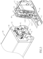
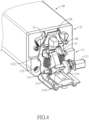
Fig. 2 to Fig. 4 are exploded views of the electronic control battery box lock inFig. 1 ; -
Fig. 5 andFig. 6 are side cross-sectional views of the electronic control battery box lock inFig. 1 ; -
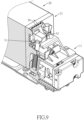
Fig. 7 to Fig. 9 are side cross-sectional views of the electronic control battery box lock inFig. 1 ; -
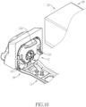
Fig. 10 to Fig. 11 are exploded views of the electronic control battery box lock inFig. 1 ; -
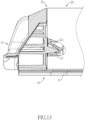
Fig. 12 andFig. 13 are side cross-sectional views of protrusion parts and recessed parts of the electronic control battery box lock inFig. 1 ; -
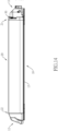
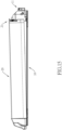
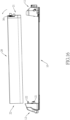
Fig. 14 to Fig. 16 are operation schematic views showing separation of a battery box inFig. 1 ; -
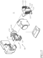
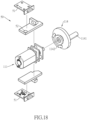
Fig. 17 andFig. 18 are exploded views of a first base latch seat of the electronic control battery box lock inFig. 1 ; and -
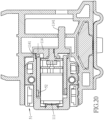
Fig. 19 andFig. 20 are sectional operation views of a latching member sensor of the electronic control battery box lock inFig. 1 . - With reference to
Fig. 1 ,Fig. 2 andFig. 17 , an electronically control battery box lock in accordance with the present invention comprises abase 10 and abattery box 20. Preferably, the electronically control battery box lock further includes amanual unlocking member 30, aguidance structure 40 and alatching member sensor 50. The present invention is preferably used on a bicycle and may be used on an electric bicycle. Meanwhile, thebase 10 is part of the bicycle frame and is preferably mounted on adown tube 90 of the bicycle frame, but it is not limited thereto, and thebase 10 may be mounted in other positions of the bicycle or applied in any other occasion. - The
battery box 20 is a compartment for holding a battery, but can also be regarded as a casing for the battery. In addition, thebattery box 20 may be a case or a casing for batteries of different sizes and uses. - With reference to
Fig. 2 ,Fig. 3 andFig. 10 , theaforementioned base 10 comprises a firstbase latch seat 11. In this embodiment, thebase 10 further includes aconnection seat 13 and a secondbase latch seat 12. Theconnection seat 13 preferably extends in a straight line. The firstbase latch seat 11 and the secondbase latch seat 12 are respectively connected to two ends of theconnection seat 13, but it is not limited thereto. Thebase 10 may be in other shapes, and the firstbase latch seat 11 and the secondbase latch seat 12 may not be located on the two ends of the straight line. - The
battery box 20 is detachably mounted on thebase 10 and comprises a firstbattery latch seat 21. In this embodiment, thebattery box 20 further includes a secondbattery latch seat 22. The firstbattery latch seat 21 and the secondbattery latch seat 22 are respectively located on two ends of thebattery box 20. Thebattery box 20 may be located between the firstbase latch seat 11 and the secondbase latch seat 12 of thebase 10. Preferably, the distance between the firstbase latch seat 11 and the secondbase latch seat 12 corresponds to the length of thebattery box 20, so that the two ends of the battery box 20 (the firstbattery latch seat 21 and the second battery latch seat 22) may respectively abut the firstbase latch seat 11 and the secondbase latch seat 12 of thebase 10. Preferably, the firstbase latch seat 11 and the secondbase latch seat 12 of thebase 10 respectively engage with the firstbattery latch seat 21 and the secondbattery latch seat 22 of thebattery box 20, but it is not limited thereto. The electronic control battery box lock may not comprise the secondbase latch seat 12 and the secondbattery latch seat 22, and thebattery box 20 can be engaged with the firstbattery latch seat 21 only through the firstbase latch seat 11. For example, a groove is formed on thebase 10, and thebattery box 20 is accommodated in the groove. The firstbattery latch seat 21 faces the groove bottom, the firstbase latch seat 11 is also located on the groove bottom, so that thebattery box 20 can be engaged only through the firstbase latch seat 11 and the firstbattery latch seat 21. - With reference to
Fig. 3 to Fig. 6 andFig. 17 , the aforementioned firstbase latch seat 11 includes anelectronic controller 111 and alatching member 112. Thelatching member 112 is movable or rotatable to engage with the firstbattery latch seat 21 under the control of theelectronic controller 111. When thelatching member 112 engages with the firstbattery latch seat 21, thebattery box 20 cannot be separated from thebase 10, and thelatching member 112 is movable or rotatable to disengage from the firstbattery latch seat 21 under the control of theelectronic controller 111. - In this embodiment, the
electronic controller 111 drives thelatching member 112 to rotate to disengage the firstbattery latch seat 21. Theelectronic controller 111 comprises a controller area network bus (CAN bus) and a Bluetooth low energy (BLE) system, and also can comprise a Global Positioning System (GPS). Therefore, theelectronic controller 111 may be controlled via wired or wireless methods preferably via a mobile application. - In this embodiment, the
latching member 112 regularly moves or rotates toward a direction of engaging the firstbattery latch seat 21. In other words, theelectronic controller 111 is only used to disengage thelatching member 112 from the firstbattery latch seat 21. During the installation of thebattery box 20, when the firstbattery latch seat 21 engages with the firstbase latch seat 11, the firstbattery latch seat 21 can push thelatching member 112 away without reversing the movement or rotation of thelatching member 112, so that thebattery box 20 is convenient to install. In addition, thelatching member 112 comprises aretreat part 1121 being preferably curved and abutted by the firstbattery latch seat 21, so as to better facilitate the firstbattery latch seat 21 to push thelatching member 112 away. - Preferably, the first
base latch seat 11 comprises at least one latchingflexible member 113. Precisely, the latchingflexible member 113 is a torsion spring and is configured to regularly rotate thelatching member 112 in the direction of engaging the firstbattery latch seat 21, but it is not limited thereto, as other methods can be used, such as changing to two opposite magnetic magnets. In addition, the latchingmember 112 may not regularly be moved or rotated in the direction of engaging the firstbattery latch seat 21, but theelectronic controller 111 directly moves the latchingmember 112 in the direction of engaging the firstbattery latch seat 21. - In this embodiment, the
electronic controller 111 is a motor (preferably a servomotor or a stepper motor) and moves or rotates the latchingmember 112 through a rotatingmember 114. Aneccentric part 1141 protrudes from the rotatingmember 114. Theelectronic controller 111 moves or rotates the latchingmember 112 in a direction away from the firstbattery latch seat 21 by rotating the rotatingmember 114, and the latchingmember 112 is disengaged from the firstbattery latch seat 21. Preferably, theeccentric part 1141 protrudes from the rotatingmember 114 along an axial direction of the rotatingmember 114 but deviates from the center of the rotatingmember 114. Therefore, after the rotatingmember 114 rotates, theeccentric part 1141 can abut against and drive the latchingmember 112 to rotate, but it is not limited thereto. Theeccentric part 1141 may also protrude radially from the periphery of the rotatingmember 114, so that the rotatingmember 114 can be regarded as a cam, and can also abut against and drive the latchingmember 112 to rotate. In addition, theelectronic controller 111 may also rotate the latchingmember 112 by pushing one end of the latchingmember 112, in which case theelectronic controller 111 may be a pressure cylinder or a linear motor. The latchingmember 112 may not rotate but move; when engaging the firstbattery latch seat 21, the latchingmember 112 is simply moved to extend into the firstbattery latch seat 21, which also prevents the firstbattery latch seat 21 from separating. - With reference to
Fig. 4 ,Fig. 5 andFig. 7 , themanual unlocking member 30 is mounted on the firstbase latch seat 11 or the firstbattery latch seat 21, and selectively engages the other of the firstbase latch seat 11 and the firstbattery latch seat 21. When the latchingmember 112 disengages the firstbattery latch seat 21 and the manual unlockingmember 30 disengages the other of the firstbase latch seat 11 and the firstbattery latch seat 21, thebattery box 20 is capable of disengaging thebase 10. - With reference to
Fig. 4 ,Fig. 8 andFig. 9 , in this embodiment, themanual unlocking member 30 is mounted on the firstbattery latch seat 21 and selectively engages with the firstbase latch seat 11. Preferably, themanual unlocking member 30 is flexible and can be triggered. Normally, at least onesupport part 31 of the manual unlockingmember 30 abuts the firstbase latch seat 11 and prevents thebattery box 20 from moving (upwardly) away from the base 10 (as shown inFig. 8 ). After triggering the manual unlockingmember 30, thesupport part 31 of the manual unlockingmember 30 is detachable from the first base latch seat 11 (as shown inFig. 9 ), and no longer prevents thebattery box 20 from disengaging from thebase 10. - With reference to
Fig. 4 ,Fig. 7 andFig. 17 , in this embodiment, the firstbase latch seat 11 comprises at least oneseparation member 115 tending to push (upwardly) the firstbattery latch seat 21 away from thebase 10. When the latchingmember 112 is disengaged from the firstbattery latch seat 21, theseparation member 115 pushes (upwardly) the firstbattery latch seat 21 away from thebase 10. Meanwhile, themanual unlocking member 30 preferably engages with the other of the firstbase latch seat 11 and the firstbattery latch seat 21. In this embodiment, thesupport part 31 of the manual unlocking member 30 (upwardly) abuts the firstbase latch seat 11, and then the manual unlockingmember 30 can be operated so that thebattery box 20 can be disengaged from thebase 10, but it is not limited thereto. The latchingmember 112 and the manual unlockingmember 30 also can be clamped at the same time, in which case the manual unlockingmember 30 can be unlocked first, and then the latchingmember 112 can be disengaged from the firstbattery latch seat 21, but it is not limited thereto. Theseparation member 115 can also be used without the manual unlockingmember 30, after the latchingmember 112 is disengaged from the firstbattery latch seat 21, the firstbattery latch seat 21 of thebattery box 20 will be pushed away from thebase 10, and the firstbattery latch seat 21 can then be separated from the firstbase latch seat 11. In addition, in this embodiment, theseparation member 115 is a flexible element and preferably is a compression spring, but it is not limited thereto. - With reference to
Fig. 2 andFig. 10 toFig. 13 , in this embodiment, when thebattery box 20 is located between the firstbase latch seat 11 and the secondbase latch seat 12 of thebase 10, the secondbattery latch seat 22 and the secondbase latch seat 12 engage with each other. When the latchingmember 112 of the firstbase latch seat 11 disengages the firstbattery latch seat 21, the secondbattery latch seat 22 may be tilted (upwardly) away from the base 10 to disengage from the secondbase latch seat 12. - In this embodiment, at least one
side protrusion part 121 and atop protrusion part 122 protrude from the secondbase latch seat 12; preferably, there are twoside protrusion parts 121. The secondbattery latch seat 22 is recessed with at least one side recessedpart 221 and a top recessedpart 222; preferably, there are two side recessedparts 221. The side recessedpart 221 and the top recessedpart 222 are configured to respectively accommodate theside protrusion part 121 and thetop protrusion part 122, but it is not limited thereto. The quantities and positions of the protrusion parts and the recessed parts can be adjusted according to need, the recessed parts may also be modified to be located on the secondbase latch seat 12, and the protrusion parts are modified to be located on the secondbattery latch seat 22. - Preferably, the top and bottom surfaces of the
side protrusion part 121 and thetop protrusion part 122 may be inclined, and the top side inner surfaces and the bottom side inner surfaces of the side recessedpart 221 and the top recessedpart 222 may be inclined, thereby facilitating the secondbattery latch seat 22 to be tilted (upwardly) away from the base 10 to disengage from the secondbase latch seat 12. - With reference to
Fig. 3 ,Fig. 5 andFig. 7 , theaforementioned guidance structure 40 is mounted on the firstbase latch seat 11 and the firstbattery latch seat 21. When the secondbattery latch seat 22 and the secondbase latch seat 12 are tilted in engagement with each other, the firstbattery latch seat 21 may be inserted into the firstbase latch seat 11 along theguidance structure 40 and toward the base 10 (downwardly), so as to prevent the firstbattery latch seat 21 from swinging (left or right) relative to the firstbase latch seat 11. Preferably, theguidance structure 40 includes at least oneguidance block 41 and at least oneguidance slot 42, and preferably there are three guidance blocks 41 and threeguidance slots 42. The guidance blocks 41 are formed on the firstbattery latch seat 21, and theguidance slots 42 are formed on the firstbase latch seat 11, but it is not limited thereto. The guidance blocks 41 may also be formed on the firstbase latch seat 11, and theguidance slots 42 may be formed on the firstbattery latch seat 21. - With reference to
Fig. 8 , in this embodiment, the place where thesupport part 31 of the manual unlockingmember 30 abuts (upwardly) the firstbase latch seat 11 is the periphery of theguidance slot 42, and the place where theseparation member 115 pushes against the firstbattery latch seat 21 is theguidance block 41, but it is not limited thereto. - With reference to
Fig. 17 to Fig. 20 , the aforementionedlatching member sensor 50 is electrically connected to theelectronic controller 111, and is configured to sense whether the latchingmember 112 moves or rotates to engage with the firstbattery latch seat 21. Preferably, the latchingmember sensor 50 includes twosensor units 51 and twosensory units 52, and the twosensor units 51 are electrically connected to theelectronic controller 111. Theelectronic controller 111 is capable of rotating the rotatingmember 114 in two opposite directions, the rotation of the rotatingmember 114 in two opposite directions will push the twosensory units 52 towards the twosensor units 51, and each of thesensory units 52 is sensed by the correspondingsensor unit 51 after being pushed. The twosensor units 51 are configured to determine whether the latchingmember 112 is unlocked or locked (engaged). - In this embodiment, a
rotating guide member 1142 protrudes from one side of the rotatingmember 114, and therotating guide member 1142 extends in an arc centered on the axis of the rotatingmember 114. The two ends of therotating guide member 1142 respectively comprise an incline, each of thesensory units 52 is mounted on a mobile seat, and the mobile seat comprises an incline. When the rotatingmember 114 rotates in two opposite directions, the two inclines of the rotatingmember 114 will respectively abut the incline of the mobile seat of thesensory unit 52, thus pushing the mobile seat and thesensory unit 52. Thesensory unit 52 is preferably a magnet, and thesensor unit 51 is preferably a Hall sensor. It is not limited thereto, as thesensory unit 52 and thesensor unit 51 can also be reversed. - With reference to
Fig. 2 ,Fig. 3 ,Fig. 12 andFig. 13 , to install thebattery box 20 in thebase 10, firstly, the secondbattery latch seat 22 at one end of thebattery box 20 is obliquely inserted into the secondbase latch seat 12 of thebase 10, so that the side recessedpart 221 and the top recessedpart 222 accommodate theside protrusion part 121 and thetop protrusion part 122 respectively. Then, theguidance block 41 of the firstbattery latch seat 21 at the other end of thebattery box 20 is downwardly inserted into the firstbase latch seat 11 along theguidance slot 42 of the firstbase latch seat 11. - During the insertion process, the
guidance block 41 in the middle of the firstbattery latch seat 21 is pushed against theretreat part 1121 of the latchingmember 112 so that the latchingmember 112 compresses the latchingflexible member 113 and rotates. Until the firstbattery latch seat 21 has moved into position, the latchingflexible member 113 again pushes the latchingmember 112 back to the original position and engages with the firstbattery latch seat 21. At this time, each of the recessedparts battery latch seat 22 also completely accommodates each of theprotrusion parts base latch seat 12. Thereby, the secondbase latch seat 12 and the firstbase latch seat 11 clamp and engage thebattery box 20 in two opposing directions, so that thebattery box 20 cannot be separated from thebase 10. - With reference to
Fig. 5 to Fig. 10 andFig. 14 to Fig. 16 , to remove thebattery box 20, firstly, theelectronic controller 111 rotates the rotatingmember 114 to rotate the latchingmember 112 away from the firstbattery latch seat 21. Then, theseparation member 115 will rapidly push (upwardly) the firstbattery latch seat 21 away from thebase 10, until the manual unlocking member 30 (upwardly) abuts the firstbase latch seat 11. Then the manual unlockingmember 30 is triggered so that the firstbattery latch seat 21 is disengaged (upwardly) from the firstbase latch seat 11, and then the secondbattery latch seat 22 is disengaged obliquely from the secondbase latch seat 12. - Preferably, in the aforementioned unlocking process, when the
electronic controller 111 begins to rotate the rotatingmember 114, if thesensor unit 51 that determines whether or not to unlock senses thesensory unit 52, thesensing unit 51 will determine that the rotatingmember 114 has reached the unlocked position, and theelectronic controller 111 will stop rotating. After a specific time (e.g., one second), theelectronic controller 111 will start to rotate the rotatingmember 114 in the reverse direction, and if thesensor unit 51 that determines whether or not to lock senses thesensory unit 52, thesensor unit 51 will determine that the rotatingmember 114 has reached the locked position, and theelectronic controller 111 will stop rotating. In the aforementioned process, when theelectronic controller 111 starts to rotate (or reverse rotation) after a specific time (e.g., two seconds), if thesensor unit 51 that determines whether or not to unlock (or thesensor unit 51 that determines whether or not to lock) has not sensed thesensory unit 52, then theelectronic controller 111 will stop rotating. The use of thesensor unit 51 and thesensory unit 52 is not limited to the above. - The present invention can lock the
battery box 20 to avoid theft, there is no need to use or carry a key, thebattery box 20 can be unlocked from the base 10 through an electronic controller (e.g., through a mobile application), so that thebattery box 20 can be removed, thus facilitating ease in use.
Claims (10)
- An electronically control battery box lock, and characterized in that the electronically control battery box lock comprises:a base (10) comprising
a first base latch seat (11) comprisingan electronic controller (111); anda latching member (112) being moveable or rotatable under the control of the electronic controller (111);a battery box (20) detachably mounted on the base (10), and comprising
a first battery latch seat (21); the latching member (112) of the first base latch seat (11) being movable or rotatable to engage with the first battery latch seat (21); when the latching member (112) engages with the first battery latch seat (21), the battery box (20) being inseparable from the base (10); the latching member (112) being moveable or rotatable to disengage the first battery latch seat (21) under the control of the electronic controller (111) of the first base latch seat (11). - The electronically control battery box lock as claimed in claim 1, whereinthe base (10) further comprises
a second base latch seat (12), the first base latch seat (11) and the second base latch seat (12) respectively located on two ends of the base (10);the battery box (20) further comprises
a second battery latch seat (22); the first battery latch seat (21) and the second battery latch seat (22) respectively located on two ends of the battery box (20); the battery box (20) detachably located between the first base latch seat (11) and the second base latch seat (12) of the base (10);when the battery box (20) is located between the first base latch seat (11) and the second base latch seat (12) of the base (10), the second battery latch seat (22) and the second base latch seat (12) engage with each other;when the latching member (112) of the first base latch seat (11) is disengaged from the first battery latch seat (21), the second battery latch seat (22) is capable of being tilted away from the base (10) to disengage from the second base latch seat (12). - The electronically control battery box lock as claimed in claim 2 further comprising:
a guidance structure (40) mounted on the first base latch seat (11) and the first battery latch seat (21); when the second battery latch seat (22) and the second base latch seat (12) are tilted and coupled to each other, the first battery latch seat (21) inserted into the first base latch seat (11) along the guidance structure (40) toward the base (10). - The electronically control battery box lock as claimed in any one of claims 1 to 3, wherein the latching member (112) tends to be moved or rotated to engage the first battery latch seat (21).
- The electronically control battery box (20) lock as claimed in any one of claims 1 to 3, wherein the electronic controller (111) comprises
a rotating member (114) comprising
an eccentric part (1141) protruding from the rotating member (114), the electronic controller (111) moving or rotating the latching member (112) in a direction away from the first battery latch seat (21) to disengage the latching member (112) from the first battery latch seat (21) by rotating the rotating member (114). - The electronically control battery box lock as claimed in any one of claims 1 to 3 further comprising:
a manual unlocking member (30) mounted on one of the first base latch seat (11) and the first battery latch seat (21), and selectively engaging the other of the first base latch seat (11) and the first battery latch seat (21); when the latching member (112) is disengaged from the first battery latch seat (21) and the manual unlocking member (30) is disengaged from said the other of the first base latch seat (11) and the first battery latch seat (21), the battery box (20) being capable of disengaging the base (10). - The electronically control battery box lock as claimed in claim 6, wherein the first base latch seat (11) comprises
at least one separation member (115) tending to push the first battery latch seat (21) away from the base (10); when the latching member (112) is disengaged from the first battery latch seat (21), the separation member (115) pushing the first battery latch seat (21) away from the base (10), thereby engaging the manual unlocking member (30) with said the other of the first base latch seat (11) and the first battery latch seat (21). - The electronically control battery box lock as claimed in any one of claims 1 to 3, wherein the first base latch seat (11) comprises
at least one separation member (115) tending to push the first battery latch seat (21) away from the base (10); when the latching member (112) is disengaged from the first battery latch seat (21), the separation member (115) pushing the first battery latch seat (21) away from the base (10). - The electronically control battery box lock as claimed in any one of claims 1 to 3 further comprising:
a latching member (112) sensor electrically connected to the electronic controller (111), and configured to sense whether the latching member (112) moves or rotates to engage the first battery latch seat (21). - The electronically control battery box (20) lock as claimed in claim 9, whereinthe latching member (112) sensor comprisestwo sensor units (51) electrically connected to the electronic controller (111); andtwo sensory units (52) respectively corresponding to the two sensor units (51);the electronic controller (111) comprises
a rotating member (114); the electronic controller (111) moving or rotating the latching member (112) by rotating the rotating member (114); the electronic controller (111) being capable of rotating the rotating member (114) in two opposite directions, the rotation of the rotating member (114) in two opposite directions respectively pushing the two sensory units (52) towards the two sensor units (51); each of the sensory units (52) sensed by the corresponding sensor unit (51) after being pushed.
Applications Claiming Priority (1)
| Application Number | Priority Date | Filing Date | Title |
|---|---|---|---|
| US202363509092P | 2023-06-20 | 2023-06-20 |
Publications (1)
| Publication Number | Publication Date |
|---|---|
| EP4480795A1 true EP4480795A1 (en) | 2024-12-25 |
Family
ID=91581017
Family Applications (1)
| Application Number | Title | Priority Date | Filing Date |
|---|---|---|---|
| EP24182169.3A Withdrawn EP4480795A1 (en) | 2023-06-20 | 2024-06-14 | Electric lock of bicycle battery |
Country Status (5)
| Country | Link |
|---|---|
| US (1) | US20240425130A1 (en) |
| EP (1) | EP4480795A1 (en) |
| JP (1) | JP3248086U (en) |
| CN (1) | CN222347210U (en) |
| TW (1) | TWM660089U (en) |
Families Citing this family (1)
| Publication number | Priority date | Publication date | Assignee | Title |
|---|---|---|---|---|
| FR3165859A1 (en) * | 2024-08-28 | 2026-03-06 | Decathlon | A device for attaching a battery to a frame, and an electric vehicle incorporating such a device. |
Citations (4)
| Publication number | Priority date | Publication date | Assignee | Title |
|---|---|---|---|---|
| DE202016104156U1 (en) * | 2016-07-28 | 2016-09-09 | Robert Bosch Gmbh | Device for securing the removal of an accumulator |
| DE102019207103A1 (en) * | 2018-05-18 | 2019-11-21 | Shimano Inc. | LOCKING DEVICE, BATTERY UNIT AND BATTERY MOUNT |
| US11235838B2 (en) * | 2016-10-13 | 2022-02-01 | Abus August Bremicker Sohne Kg | Battery lock for an electric vehicle |
| US11572132B2 (en) * | 2018-05-07 | 2023-02-07 | Trek Bicycle Corporation | Bicycle battery assembly |
-
2024
- 2024-05-28 TW TW113205453U patent/TWM660089U/en unknown
- 2024-05-30 CN CN202421214135.3U patent/CN222347210U/en active Active
- 2024-06-04 JP JP2024001823U patent/JP3248086U/en active Active
- 2024-06-12 US US18/740,654 patent/US20240425130A1/en active Pending
- 2024-06-14 EP EP24182169.3A patent/EP4480795A1/en not_active Withdrawn
Patent Citations (4)
| Publication number | Priority date | Publication date | Assignee | Title |
|---|---|---|---|---|
| DE202016104156U1 (en) * | 2016-07-28 | 2016-09-09 | Robert Bosch Gmbh | Device for securing the removal of an accumulator |
| US11235838B2 (en) * | 2016-10-13 | 2022-02-01 | Abus August Bremicker Sohne Kg | Battery lock for an electric vehicle |
| US11572132B2 (en) * | 2018-05-07 | 2023-02-07 | Trek Bicycle Corporation | Bicycle battery assembly |
| DE102019207103A1 (en) * | 2018-05-18 | 2019-11-21 | Shimano Inc. | LOCKING DEVICE, BATTERY UNIT AND BATTERY MOUNT |
Also Published As
| Publication number | Publication date |
|---|---|
| JP3248086U (en) | 2024-08-27 |
| TWM660089U (en) | 2024-09-01 |
| US20240425130A1 (en) | 2024-12-26 |
| CN222347210U (en) | 2025-01-14 |
Similar Documents
| Publication | Publication Date | Title |
|---|---|---|
| US20240425130A1 (en) | Electronically control battery box lock | |
| US6761051B1 (en) | Electric padlock | |
| US11529711B2 (en) | Sanding machine, operating method thereof and working baseplate disassembly-assembly method | |
| JP4624912B2 (en) | Electric steering lock device | |
| US11879274B2 (en) | Lock assembly for a bicycle | |
| EP3196388A1 (en) | Redundant actuation lock decoupling system and methods of use | |
| JP2004231123A (en) | Electric steering lock device | |
| CN114233999A (en) | Quick assembly disassembly device and photographic equipment | |
| JP3706934B2 (en) | Vehicle locking device with enhanced anti-theft function | |
| CN114484189A (en) | Quick assembly disassembly device and photographic equipment | |
| TW202508886A (en) | Electronic frame lock | |
| JP6276421B2 (en) | Improved ignition switch with steering lock | |
| EP3681789A1 (en) | An automated handle bar lock for vehicles | |
| CN118024974B (en) | Electric rotation locking structure and mode of seat and child safety seat | |
| CN108820082B (en) | locks for vehicles | |
| CN213659569U (en) | Shared power pushers and shared power devices | |
| CN218257987U (en) | Push to unlock car mount | |
| TWI856174B (en) | Holding device for releasably holding an energy store on a frame, in particular on a bicycle frame | |
| KR100780023B1 (en) | Steering lock device interworking with electronic authentication system and its manufacturing method | |
| TW201938896A (en) | Switching device that can be unlocked by way of detection | |
| EP3707034B1 (en) | A multi-function smart ignition lock for vehicles | |
| JP3905685B2 (en) | Engine starter for vehicle | |
| JP4173982B2 (en) | Cabinet locking and unlocking device | |
| CN224061083U (en) | Electric control foot stand lock for bicycle | |
| CN111422284B (en) | A lock bracket |
Legal Events
| Date | Code | Title | Description |
|---|---|---|---|
| PUAI | Public reference made under article 153(3) epc to a published international application that has entered the european phase |
Free format text: ORIGINAL CODE: 0009012 |
|
| STAA | Information on the status of an ep patent application or granted ep patent |
Free format text: STATUS: THE APPLICATION HAS BEEN PUBLISHED |
|
| AK | Designated contracting states |
Kind code of ref document: A1 Designated state(s): AL AT BE BG CH CY CZ DE DK EE ES FI FR GB GR HR HU IE IS IT LI LT LU LV MC ME MK MT NL NO PL PT RO RS SE SI SK SM TR |
|
| STAA | Information on the status of an ep patent application or granted ep patent |
Free format text: STATUS: THE APPLICATION IS DEEMED TO BE WITHDRAWN |
|
| 18D | Application deemed to be withdrawn |
Effective date: 20250626 |