EP4480791A1 - Vehicular hood - Google Patents
Vehicular hood Download PDFInfo
- Publication number
- EP4480791A1 EP4480791A1 EP22926951.9A EP22926951A EP4480791A1 EP 4480791 A1 EP4480791 A1 EP 4480791A1 EP 22926951 A EP22926951 A EP 22926951A EP 4480791 A1 EP4480791 A1 EP 4480791A1
- Authority
- EP
- European Patent Office
- Prior art keywords
- hood
- outer panel
- vehicle
- wall member
- longitudinal direction
- Prior art date
- Legal status (The legal status is an assumption and is not a legal conclusion. Google has not performed a legal analysis and makes no representation as to the accuracy of the status listed.)
- Withdrawn
Links
Images


Classifications
-
- B—PERFORMING OPERATIONS; TRANSPORTING
- B62—LAND VEHICLES FOR TRAVELLING OTHERWISE THAN ON RAILS
- B62D—MOTOR VEHICLES; TRAILERS
- B62D25/00—Superstructure or monocoque structure sub-units; Parts or details thereof not otherwise provided for
- B62D25/08—Front or rear portions
- B62D25/10—Bonnets or lids, e.g. for trucks, tractors, busses, work vehicles
- B62D25/105—Bonnets or lids, e.g. for trucks, tractors, busses, work vehicles for motor cars
-
- B—PERFORMING OPERATIONS; TRANSPORTING
- B62—LAND VEHICLES FOR TRAVELLING OTHERWISE THAN ON RAILS
- B62D—MOTOR VEHICLES; TRAILERS
- B62D29/00—Superstructures, understructures, or sub-units thereof, characterised by the material thereof
- B62D29/001—Superstructures, understructures, or sub-units thereof, characterised by the material thereof characterised by combining metal and synthetic material
- B62D29/005—Superstructures, understructures, or sub-units thereof, characterised by the material thereof characterised by combining metal and synthetic material preformed metal and synthetic material elements being joined together, e.g. by adhesives
Definitions
- the present invention relates to a hood for a vehicle.
- a hood (bonnet).
- the hood is attached to a vehicle body by hinges.
- the hood generally has a double-plate structure with metal outer and inner panels in consideration of its rigidity and strength. Steel is commonly used as its metal, but aluminum alloys are sometimes used to reduce vehicle weight in order to improve vehicle dynamics and fuel economy.
- a hood made of FRP is also available but is not common.
- a Patent Literature 1 listed below discloses a hood for a vehicle that has a double-plate structure.
- Patent Literature 1 Japanese Patent Application Publication No. 2004-82796
- an internal combustion engine (ICE) and a motor generator (MG) are installed in its compartment as well as an electronic control module, such as an inverter, and a transmission unit (transfer unit).
- an electronic control module and a transfer unit are installed in its compartment in addition to a motor generator.
- the number of other supplemental devices also tends to increase, and there is a desire to expand the volume of said compartment.
- a hood with a three-dimensional structure that requires height in the vertical direction inhibits expansion of the volume. In other words, there is a need to reduce the height of the hood in order to improve design flexibility.
- a hood needs to meet vehicle body performance requirements related to vehicle frontal collisions. Specifically, a hood is required to be bent at the middle in its longitudinal direction during a frontal collision (collision energy absorption and prevention of its intrusion into the passenger compartment). Therefore, the present invention is to provide a hood for a vehicle with a novel structure that improves design flexibility, reduces weight, and satisfies required frontal-collision performance.
- a hood for a vehicle includes an outer panel that is made of metal and is convex upwardly, an inner panel that is made of metal and is disposed beneath the outer panel, and at least one wall member that is made of plastic and connects a bottom face of the outer panel to a top face of the inner panel.
- a width of a cross-bridge portion of the inner panel in a longitudinal direction of the vehicle is smaller than a length of the outer panel in the longitudinal direction.
- the cross-bridge portion extends straight in a lateral direction of the vehicle and is located beneath a front portion of the outer panel, and both ends thereof are joined to both side edges of the outer panel, respectively.
- a hood for a vehicle will be described with reference to the drawings.
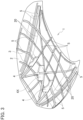
- a hood 1 according to a first embodiment will be described with reference to Fig. 1 and Fig. 2 .
- Fig. 1 and Fig. 2 are perspective views in which the hood 1 is viewed from beneath with a bottom face of the hood 1 is oriented upward.
- the hood 1 includes a metal outer panel 2 and a metal inner panel 3.
- the outer panel 2 and the inner panel 3 are directly joined at both ends in a lateral direction of a vehicle, but a gap is formed between them.
- the two panels are joined by pinching the side edges of the inner panel 3 when hemming the perimeter edges of the outer panel 2 (adhesives or sealants may be used in combination).
- Wall members 4 made of plastic are provided in the above-mentioned gap, and the wall members 4 connect the bottom face of the outer panel 2 to the top face of the inner panel 3.
- Tape members 5 made of plastic are also attached to the bottom face of the outer panel 2 to improve the out-of-plane rigidity of the outer panel 2 (i.e., of the hood 1).
- the tape members 5 extend in the above-mentioned lateral direction, in a longitudinal direction which is approximately orthogonal to the lateral direction, and in diagonal directions each of which intersects both the lateral direction and the lateral direction.
- the above-mentioned wall members 4 are disposed on the tape members 5.
- the outer panel 2 in the present embodiment is made of steel or aluminum alloy.
- the outer panel 2 is manufactured from a metal sheet by press forming or incremental forming.
- the outer panel 2 is made convex upwardly.
- Undulations are also formed in the outer panel 2, and ridge lines and valley lines (so-called character lines 20) extend in the longitudinal direction.
- the character lines 20 give an aesthetic appearance to the hood 1 and improve the rigidity of the hood 1.
- Some of the above-mentioned tape members 5 extending in the longitudinal direction are attached to the bottom face of the outer panel 2 along these undulations (the character lines 20).
- the inner panel 3 is also made of steel or aluminum alloy, and is generally made of the same material as the material of the outer panel 2.
- the inner panel 3 is also manufactured from a metal sheet by press forming or incremental forming.
- the inner panel 3 has a U-shape, including a cross-bridge portion 3C and a pair of side-extension portions 3S.
- the cross-bridge portion 3C extends almost straight in the lateral direction.
- the width of the cross-bridge section 3C in the longitudinal direction is smaller than the length of the outer panel 2 in the longitudinal direction.
- the cross-bridge section 3C is located beneath the front portion of the outer panel 2. In the center of the cross-bridge portion 3C, a locking portion 30 that engages a locking striker on a vehicle body is formed.
- the side-extension portions 3S extend in the longitudinal direction. More particularly, the side-extension portions 3S extend rearward from the side ends of the cross-bridge portion 3C along the side edges of the outer panel 2, respectively.
- a hinge 31 for attaching the hood 1 to the vehicle body is attached to each rear end of the side-extension portions 3S by means of bolts and nuts.
- a reinforcement 32 is welded on the upper face of the rear end to ensure the mounting strength of the hinge 31. That is, the reinforcement 32, the inner panel 3 and the hinge 31 are jointly tightened by the bolts and the nuts welded on an upper face of the reinforcement 32.
- a bracket 33 for aligning the vertical position of the closed hood 1 with respect to the vehicle body is welded at the middle of the side-extension portion 3S in the longitudinal direction (a rubber bush attached to the bracket 33 is not shown in the drawings).
- the wall members 4 are attached in this gap to connect the bottom face of the outer panel 2 to the top face of the inner panel 3.
- three wall members 4 are provided on the left side, the center, and the right side in the lateral direction.
- the center wall member 4 is positioned at the location of the above-mentioned locking section 30.
- Each of the wall members 4 has a plate-wall shape extending in the longitudinal direction.
- the wall members 4 in the present embodiment are made of Carbon Fiber Reinforced Plastic (CFRP).
- CFRP Carbon Fiber Reinforced Plastic
- the matrix resin of CFRP can be a thermosetting resin or a thermoplastic resin (CFRTP).
- the carbon fibers of CFRP (including CFRTP) in the present embodiment are continuous fibers, but may also be non-continuous fibers. Furthermore, the continuous carbon fibers are oriented in the longitudinal direction.
- the wall members 4 may be made of Fiber Reinforced Plastic (FRP) containing reinforcing fibers other than carbon fibers. As the reinforcing fibers, glass fibers, aramid fibers or the like can be adopted. The wall members 4 do not have to contain reinforcing fibers as long as they are made of plastic.
- FRP Fiber Reinforced Plastic
- each of the tape members 5 is also made of CFRP. And its carbon fibers are continuous fibers and oriented in the extending direction of the tape members 5.
- the matrix resin of CFRP may be thermosetting resin or thermoplastic resin, and the carbon fibers may be continuous or non-continuous fibers.
- the matrix resin is a thermoplastic resin and continuous carbon fibers are used.
- the tape members 5 may be made of FRP containing reinforcing fibers other than carbon fibers, or may not have to contain reinforcing fibers as long as they are made of plastic.
- the tape members 5 in the present embodiment are formed by laminating a thin CFRTP tape material (30 mm wide and 0.2 mm thick) multiple times.
- the height (thickness) of the tape member 5 is adjusted according to the number of lamination times.
- the rigidity of the outer panel 2 can be increased.
- the height of the tape member 5 is adjusted according to the rigidity required at the position where it is provided.
- the height of the tape member 5 between the outer panel 2 and the above-mentioned reinforcement 32 is made large, and the tape member 5 connects the bottom face of the outer panel 2 to the top face of the reinforcement 32 to improve the strength of the attachment portion of the hinge 31.
- the tape member 5 is formed by stacking the above-mentioned tape materials by an NC-controlled automatic laminating device.
- the automatic laminating device impregnates the carbon fibers, which are continuous fiber, with melted thermoplastic resin while extruding it in tape form from a nozzle located at the tip of a robot arm.
- the extruded tape material is laminated on the bottom face of the outer panel 2 oriented upward and then cured as its temperature drops to be fixed on the outer panel 2 as the tape member 5.
- a surface treatment is applied in advance on the bottom face of the outer panel 2 to improve the fixing strength of the tape member 5.
- the surface treatment is done by laser processing or chemical treatment. These surface treatments form micro asperity, and the resin enters into the micro asperity to develop an anchoring effect. Silane coupling may also be used as the surface treatment.
- the method of forming the tape member 5 is not limited to the above method.
- the tape material 5, which has been adjusted to the desired height in advance, may be attached to the bottom face of the outer panel 2 automatically or manually.
- the tape member 5 may also be formed by laminating tape materials using thermosetting resin instead of thermoplastic resin with the above-mentioned automatic laminating device.
- the tape member 5 may be fixed on the bottom face of the outer panel 2 by an adhesive or sealant.
- the tape member 5 may be previously molded using a molding machine capable of injection molding a tape with varying molding height, and then the tape member 5 may be fixed on the bottom face of the outer panel 2.
- the wall member 4 is formed by further laminating the above tape materials continuously after the tape member 5 is laminated on the bottom face of the outer panel 2.
- the wall member 4 is formed by further laminating 100 to 200 layers of the tape materials on the tape member 5 using the above-mentioned automatic laminating device.
- the method of forming the wall member 4 is not limited to this method.
- the wall member 4 previously made may be adhered onto the tape member 5.
- the tape materials may also be laminated using thermosetting resin instead of thermoplastic resin by using the above-mentioned automatic laminating device.
- the wall member 4 may be fixed on the tape material 5 by means of an adhesive or sealant. Alternatively, the wall member 4 may be previously molded and then fixed on the tape member 5.
- the wall member 4 is provided together with the tape member 5.
- the wall member 4 may be fixed directly on the bottom face of the outer panel 2 without the tape member 5 interposed.
- the method similar to the above-mentioned method of fixing the tape member 5 on the bottom face of the outer panel 2 can be adopted as the method of fixing the wall member 4 on the bottom face of the outer panel 2.
- the wall member 4 can be formed directly on the bottom face of the outer panel 2 by laminating the tape materials using the above-mentioned automatic laminating device.
- the wall member 4 may be formed by fabricating a filament made by impregnating continuous carbon fibers with resin by use of a 3D printer (CFRP-FMD method: Fused Deposition Modeling).
- Fig. 1 the structure shown in Fig. 1 is constructed before the hood 1 is painted in the present embodiment. This process is preferable in consideration of the joint strength between the wall member 4 and the tape member 5, and the outer panel 2 and the inner panel 3.
- the wall members 4 and the tape members 5 may be fixed on the surface of the outer panel 2 and the inner panel 3 after the outer panel 2 and the inner panel 3 are painted.
- the wall members 4 and the tape members 5 are formed of thermoplastic resin (CFRTP) in the present embodiment.
- CFRTP thermoplastic resin
- the inner panel 3 is fixed on the wall members 4 with adhesive or sealant after forming the wall members 4 and the tape members 5 on the bottom face of the outer panel 2 as described above.
- the reinforcements 32 are also fixed to the ends of the tape members 5 by adhesive or sealant.
- the both ends of the cross-bridge portion 3C of the inner panel 3 (and the side edges of the side-extension portion 3S) are joined with the perimeter edges of the outer panel 2, respectively, by hemming the perimeter edges of the outer panel 2.
- the wall members 4 and the tape members 5 are formed with CFRP of thermosetting resin
- the wall members 4 and the tape members 5 are formed on the bottom face of the outer panel 2 with pre-cured prepreg, and then the inner panel 3 with the reinforcements 32 welded thereon is placed on the wall members 4. Then, the prepreg is cured in an oven or the like.
- the thermosetting resin matrix resin
- the perimeter edge of the outer panel 2 may be hemmed before or after the prepreg is cured.
- the width of the cross-bridge portion 3C of the inner panel 3 in the longitudinal direction is smaller than the length of the outer panel 2 in the longitudinal direction, and the cross-bridge portion 3C is located beneath the front portion of the outer panel 2.
- both ends of the cross-bridge portion 3C are joined to both side edges of the outer panel 2, respectively.
- the bottom face of the outer panel 2 and the top face of the inner panel 3 are connected by the wall members 4 made of plastic. Since the outer panel 2, the inner panel 3 and the wall members 4 form a three-dimensional closed-cross-section structure, the out-of-plane rigidity, the torsional rigidity and the bending rigidity of the hood 1 can be ensured. In addition, since the size of the metal inner panel 3 is made small, the weight of the hood 1 can be reduced. Although the size of the inner panel 3 is small, the above-mentioned rigidities can be ensured due to the existence of the wall members 4.
- the cross-bridge portion 3C of the inner panel 3 is located beneath the front portion of the outer panel 2. This allows the volume of the rear space in the engine/motor compartment to be expanded, and thereby the design flexibility of the various units in the compartment can be enhanced. Furthermore, the modeling flexibility of the hood 1 itself can also be enhanced. Furthermore, pedestrian protection performance can be improved by leaving the upper rear space in the compartment. Furthermore, in the event of a vehicle frontal collision, the impact load is input to the front end of the outer panel 2, but the load can also be received by the inner panel 3 while mitigating the stress through the wall members 4.
- the hood 1 can be bent at the low-strength portion behind the cross-bridge portion 3C, i.e., at the middle of the hood 1 in the longitudinal direction.
- the required frontal-collision performance can also be satisfied.
- the inner panel 3 also has a pair of the side-extension portions 3S extending from both ends of the cross-bridge portion 3C along both side edges of the outer panel 2, respectively. That is, the inner panel 3 as a whole has a U-shape having a size smaller than that of the outer panel 2. This further improves the rigidity of the hood 1 while reducing the weight of the hood 1 as described above. Even though the inner panel 3 has such a U-shape, the side-extension portions 3S do not obstruct the volume expansion of the rear space in the compartment described above. Therefore, the above-mentioned enhancements in the design flexibility and the modeling flexibility are not inhibited. Furthermore, it is possible to provide the attachment portions of the hinges 31 at the rear ends of the side-extension portions 3S, which are required to have sufficient strength.
- the plural plastic tape members 5 are also extended on the bottom face of the outer panel 2. This further improves the rigidity of the hood 1. If metal members are welded to the bottom face of the outer panel 2 to reinforce it, weld marks will appear on the top face of the outer panel 2 or the outer panel 2 will be distorted by heat. In a case where the plastic tape members 5 are fixed on the bottom face of the outer panel 2, the appearance of the outer panel 2 will not be disturbed. Also, the plastic tape members 5 are small in weight and do not hinder the weight reduction. The inner panel 3 would rather be made smaller by providing the tape members 5, and further weight reduction is possible. Furthermore, the tape members 5 can flex and deform under large loads and thus do not deteriorate pedestrian protection performance. Rather, it is easier to balance the rigidity of the hood 1 with the pedestrian protection performance. Furthermore, in the event of a frontal collision, they can improve collision energy absorption of the hood 1.
- the tape members 5 are formed of carbon fiber reinforced plastic (CFRP). And the carbon fibers of the carbon fiber reinforced plastic are continuous fibers, and the continuous fibers are oriented in the extending direction of the tape member 5.
- CFRP is lightweight but has high rigidity, and thereby it can facilitate further weight reduction.
- the height of the tape member 5 can be reduced compared to forming the tape member 5 using only plastic, and thus the compartment volume can be further expanded. As a result, the design flexibility and the modeling flexibility can be further improved. Furthermore, it becomes easier to ensure the rigidity of the hood 1 by orienting the continuous carbon fibers in the extending direction.
- the tape members 5 are extended in the longitudinal direction, it is preferable for satisfying the above-mentioned required performance against a frontal collision. Furthermore, if the tape members 5 are also extended in the lateral direction and thus the tape members 5 are arranged in a grid pattern, the rigidity of the hood 1 can be effectively secured. In addition, since the rigidity of the hood 1 can be totally improved, its further weight reduction can be done by reducing the thickness of the outer panel 2.
- the rigidity of the hood 1 can be more effectively secured when the tape members 5 are also extended in the diagonal directions. In particular, it can effectively resist local bending and twisting.
- the two tape members 5 extending in the diagonal directions are located above (beneath in the drawings) a locking portion 30. This makes it possible for the tape members 5 and the outer panel 2 to also receive the load input to the locking portion 30 of the inner panel 3 via the central wall member 4 when the hood 1 is closed.
- the rigidity of the hood 1 can be more effectively secured when the tape member 5 is also extended along the perimeter edges of the outer panel 2.
- the perimeter edges of the outer panel 2 are prone to stress and deformation when a load applies thereto. Therefore, the outer panel 2 can be protected by extending the tape members 5 along the perimeter edges.
- the rigidity of the hood 1 can be more effectively secured when the tape members 5 are also extended along the undulations (the ridge or valley lines: the character lines 20) of the outer panel 2.
- the position and shape of the undulations may be sometimes limited due to restrictions on the rigidity and the strength required for the hood 1.
- the rigidity and the strength can be secured by the tape members 5, the forming flexibility of the undulations on the outer panel 2 can be enhanced. As a result, the design flexibility and the modeling flexibility can be further improved.
- the wall member 4 has a plate-wall shape extending long in the longitudinal direction, and it is preferable for satisfying the above-mentioned required frontal-collision performance.
- the impact load input to the front end of the outer panel 2 during a frontal collision can be transmitted to the inner panel 3 while mitigating the stress through the wall members 4.
- the wall members 4, which extend in the longitudinal direction, are less likely to fall down in the longitudinal direction, and thereby it becomes easier to bend the hood 1 at the middle of the hood 1 in the longitudinal direction.
- the outer panel 2 can also receive the load input to the inner panel 3 via the wall members 4 when the hood 1 is closed.
- the wall members 4 are formed of carbon fiber reinforced plastic (CFRP). And the carbon fibers of the carbon fiber reinforced plastic are continuous fibers, and the continuous fibers are oriented in the extending direction of the wall member 4.
- CFRP is lightweight but has high rigidity, and thereby it facilitates further weight reduction.
- the height of the wall member 4 can be reduced compared to forming the wall member 4 using only plastic, and thus the volume beneath the cross-bridge portion 3C, i.e., the volume of the front side of the compartment, can be expanded.
- the design flexibility and the modeling flexibility can be further improved.
- the CFRP wall members 4 extending in the longitudinal direction are formed on the CFRP tape members 5 extending in the longitudinal direction. And their continuous unit fibers are oriented in the extending direction. Therefore, the above-mentioned advantages brought by the CFRP tape members 5 including the continuous carbon fibers and the above-mentioned advantages brought by the CFRP wall members 4 including the continuous carbon fibers can be realized synergistically.
- the wall members 4 and the tape members 5 are formed by laminating the tape materials and thus these members can be formed continuously, both the manufacturing equipment and the manufacturing process can be simplified.
- a hood 1 according to a second embodiment will be described with reference to Fig. 3 .
- its central wall member 4X has a cross-wall shape formed by two plate-walls extending long in the diagonal directions each of which intersects both the lateral direction and the longitudinal direction, instead of the plate-wall shape extending long in the longitudinal direction in the embodiment.
- Other configurations are similar to those in the hood 1 of the first embodiment. Therefore, identical and equivalent configurations are labelled with the identical numbers and their detailed descriptions will be omitted.
- the wall member 4X is located beneath the locking portion 30 of the inner panel 3 and is formed on the intersection point of the tape members 5 extended in the diagonal directions. Both the wall member 4X and the tape members 5 are made of CFRTP, and their continuous carbon fibers are oriented in the extending direction.
- the method of forming the wall member 4X and fixing it to the outer panel 2 and the inner panel 3 is the same as that in the first embodiment. Since the left and right wall members 4 also extend in the longitudinal direction in this embodiment, the above-mentioned advantages of the first embodiment can be also brought by the present embodiment.
- the wall member 4X is also formed in the above-mentioned cross-wall shape. Also with the wall member 4X like this, the impact load input to the front end of the outer panel 2 during a frontal collision can be transmitted to the inner panel 3 via the wall member 4X (and the wall members 4) while mitigating the stress.
- the wall member 4X has the cross-wall shape and is less likely to fall down in the longitudinal direction, and thereby it becomes easier to bend the hood 1 in the middle of the hood 1 in the longitudinal direction.
- the outer panel 2 can also receive the load input to the inner panel 3 via the wall member 4X (and the wall members 4) when the hood 1 is closed.
- the wall member 4X has the cross-wall shape, the hood 1 can more effectively resist its torsional deformation.
- the wall member 4X has two plate-walls extending in the diagonal directions, and it can contribute to improving the rigidity in the diagonal directions.
- the two plate-walls form the cross-wall shape, it can contribute to improving the rigidity not only in the diagonal directions but also in the longitudinal direction and the lateral direction.
- the wall member 4X is located above (beneath in the drawings) the locking portion 30, and this makes it possible for the tape members 5 and the outer panel 2 to also receive the load input to the locking portion 30 of the inner panel 3 via the wall member 4X when the hood 1 is closed.
- the wall member 4X is formed of carbon fiber reinforced plastic (CFRP). And the carbon fibers of the carbon fiber reinforced plastic are continuous fibers, and the continuous fibers are oriented in the extending direction of the wall member 4X.
- CFRP is lightweight but has high rigidity, and thereby it facilitates further weight reduction.
- the height of the wall member 4X can be reduced compared to forming the wall member 4X using only plastic, and thus the volume beneath the cross-bridge portion 3C, i.e., the volume of the front side of the compartment, can be expanded.
- the design flexibility and the modeling flexibility can be further improved.
- the wall member 4X extending the diagonal directions is formed on the CFRP tape members 5 extending in the diagonal directions. And its continuous unit fibers are oriented in the extending directions. Therefore, the above-mentioned advantage brought by the CFRP tape members 5 including the continuous carbon fibers and the above-mentioned advantages brought by the CFRP wall member 4X including the continuous carbon fibers can be realized synergistically.
- the wall members 4 and the tape members 5 are formed by laminating the tape materials and thus these members can be formed continuously, both the manufacturing equipment and the manufacturing process can be simplified.
- the wall member 4 in the above embodiments has a shape long in the longitudinal direction, but each may have a columnar shape with a short length in the longitudinal direction.
- the wall member 4 may have a circular or polygonal hollow cylindrical wall shape (like a tower shape).
- the wall member 4 may have a solid cylindrical shape instead of the hollow cylindrical shape.
- the inner panel 3 in the above embodiment has the U-shape with the cross-bridge portion 3C and the side-extension portions 3 S.
- the side-extension portion 3S may be also extended further forward than the cross-bridge portion 3C, in which case the inner panel 3 has an H-shape. That is, this H shape is one of variations of the U-shape.
Landscapes
- Engineering & Computer Science (AREA)
- Chemical & Material Sciences (AREA)
- Combustion & Propulsion (AREA)
- Transportation (AREA)
- Mechanical Engineering (AREA)
- Architecture (AREA)
- Structural Engineering (AREA)
- Superstructure Of Vehicle (AREA)
Abstract
Description
- The present invention relates to a hood for a vehicle.
- An engine/motor compartment at a front section of a vehicle is covered by a hood (bonnet). The hood is attached to a vehicle body by hinges. The hood generally has a double-plate structure with metal outer and inner panels in consideration of its rigidity and strength. Steel is commonly used as its metal, but aluminum alloys are sometimes used to reduce vehicle weight in order to improve vehicle dynamics and fuel economy. A hood made of FRP is also available but is not common. A Patent Literature 1 listed below discloses a hood for a vehicle that has a double-plate structure.
- Many holes are formed on its inner panel to reduce the weight of the hood, but its size is the same as the size of its outer panel. By hemming the perimeter edges of the outer panel with the perimeter edges of the inner panel, the outer panel and the inner panel are secured to each other. Considering the appearance of the outer panel surface, the inner panel is not welded to the outer panel, but they are joined to each other face to face by forming a gap between them and filling the gap with a sealant. This three-dimensional structure ensures out-of-plane rigidity.
- Patent Literature 1:
Japanese Patent Application Publication No. 2004-82796 - In a hybrid electric vehicle (HEV), an internal combustion engine (ICE) and a motor generator (MG) are installed in its compartment as well as an electronic control module, such as an inverter, and a transmission unit (transfer unit). Also in a battery electric vehicle having no ICE, an electronic control module and a transfer unit, which are mentioned above, are installed in its compartment in addition to a motor generator. The number of other supplemental devices also tends to increase, and there is a desire to expand the volume of said compartment. Here, a hood with a three-dimensional structure that requires height in the vertical direction inhibits expansion of the volume. In other words, there is a need to reduce the height of the hood in order to improve design flexibility.
- On the other hand, there is another strong demand for a hood to be lightweight in order to reduce carbon dioxide emissions (i.e., improve fuel economy) in recent years. Furthermore, a hood needs to meet vehicle body performance requirements related to vehicle frontal collisions. Specifically, a hood is required to be bent at the middle in its longitudinal direction during a frontal collision (collision energy absorption and prevention of its intrusion into the passenger compartment). Therefore, the present invention is to provide a hood for a vehicle with a novel structure that improves design flexibility, reduces weight, and satisfies required frontal-collision performance.
- A hood for a vehicle according to an aspect of the present invention includes an outer panel that is made of metal and is convex upwardly, an inner panel that is made of metal and is disposed beneath the outer panel, and at least one wall member that is made of plastic and connects a bottom face of the outer panel to a top face of the inner panel. A width of a cross-bridge portion of the inner panel in a longitudinal direction of the vehicle is smaller than a length of the outer panel in the longitudinal direction. The cross-bridge portion extends straight in a lateral direction of the vehicle and is located beneath a front portion of the outer panel, and both ends thereof are joined to both side edges of the outer panel, respectively.
- According to the aspect, improvement of design flexibility, weight reduction and required frontal-collision performance can be brought due to its novel structure.
-
- [
FIG. 1] FIG. 1 is a perspective view showing a bottom face of a hood according to a first embodiment. - [
FIG. 2] FIG. 2 is a perspective view showing a state where an inner panel is removed from the hood. - [
FIG. 3] FIG. 3 is a perspective view showing a bottom face of a hood according to a second embodiment in a state where its inner panel is removed therefrom. - Hereinafter, a hood for a vehicle according to embodiments will be described with reference to the drawings. First, a hood 1 according to a first embodiment will be described with reference to
Fig. 1 andFig. 2 . Note thatFig. 1 andFig. 2 are perspective views in which the hood 1 is viewed from beneath with a bottom face of the hood 1 is oriented upward. - The hood 1 according to the first embodiment includes a metal
outer panel 2 and a metalinner panel 3. Theouter panel 2 and theinner panel 3 are directly joined at both ends in a lateral direction of a vehicle, but a gap is formed between them. The two panels are joined by pinching the side edges of theinner panel 3 when hemming the perimeter edges of the outer panel 2 (adhesives or sealants may be used in combination). -
Wall members 4 made of plastic are provided in the above-mentioned gap, and thewall members 4 connect the bottom face of theouter panel 2 to the top face of theinner panel 3.Tape members 5 made of plastic are also attached to the bottom face of theouter panel 2 to improve the out-of-plane rigidity of the outer panel 2 (i.e., of the hood 1). Thetape members 5 extend in the above-mentioned lateral direction, in a longitudinal direction which is approximately orthogonal to the lateral direction, and in diagonal directions each of which intersects both the lateral direction and the lateral direction. The above-mentionedwall members 4 are disposed on thetape members 5. - Each component will be described in more detail below.
- The
outer panel 2 in the present embodiment is made of steel or aluminum alloy. Theouter panel 2 is manufactured from a metal sheet by press forming or incremental forming. Theouter panel 2 is made convex upwardly. Undulations are also formed in theouter panel 2, and ridge lines and valley lines (so-called character lines 20) extend in the longitudinal direction. Thecharacter lines 20 give an aesthetic appearance to the hood 1 and improve the rigidity of the hood 1. Some of the above-mentionedtape members 5 extending in the longitudinal direction are attached to the bottom face of theouter panel 2 along these undulations (the character lines 20). - The
inner panel 3 is also made of steel or aluminum alloy, and is generally made of the same material as the material of theouter panel 2. Theinner panel 3 is also manufactured from a metal sheet by press forming or incremental forming. Theinner panel 3 has a U-shape, including across-bridge portion 3C and a pair of side-extension portions 3S. Thecross-bridge portion 3C extends almost straight in the lateral direction. The width of thecross-bridge section 3C in the longitudinal direction is smaller than the length of theouter panel 2 in the longitudinal direction. Thecross-bridge section 3C is located beneath the front portion of theouter panel 2. In the center of thecross-bridge portion 3C, alocking portion 30 that engages a locking striker on a vehicle body is formed. - On the other hand, the side-
extension portions 3S extend in the longitudinal direction. More particularly, the side-extension portions 3S extend rearward from the side ends of thecross-bridge portion 3C along the side edges of theouter panel 2, respectively. Ahinge 31 for attaching the hood 1 to the vehicle body is attached to each rear end of the side-extension portions 3S by means of bolts and nuts. Areinforcement 32 is welded on the upper face of the rear end to ensure the mounting strength of thehinge 31. That is, thereinforcement 32, theinner panel 3 and thehinge 31 are jointly tightened by the bolts and the nuts welded on an upper face of thereinforcement 32. Abracket 33 for aligning the vertical position of the closed hood 1 with respect to the vehicle body is welded at the middle of the side-extension portion 3S in the longitudinal direction (a rubber bush attached to thebracket 33 is not shown in the drawings). - Since the
outer panel 2 is convex upwardly and thecross-bridge portion 3C of theinner panel 3 extends straight, the gap is formed between them. Thewall members 4 are attached in this gap to connect the bottom face of theouter panel 2 to the top face of theinner panel 3. In the present embodiment, threewall members 4 are provided on the left side, the center, and the right side in the lateral direction. Thecenter wall member 4 is positioned at the location of the above-mentionedlocking section 30. Each of thewall members 4 has a plate-wall shape extending in the longitudinal direction. Thewall members 4 in the present embodiment are made of Carbon Fiber Reinforced Plastic (CFRP). The matrix resin of CFRP can be a thermosetting resin or a thermoplastic resin (CFRTP). The carbon fibers of CFRP (including CFRTP) in the present embodiment are continuous fibers, but may also be non-continuous fibers. Furthermore, the continuous carbon fibers are oriented in the longitudinal direction. Thewall members 4 may be made of Fiber Reinforced Plastic (FRP) containing reinforcing fibers other than carbon fibers. As the reinforcing fibers, glass fibers, aramid fibers or the like can be adopted. Thewall members 4 do not have to contain reinforcing fibers as long as they are made of plastic. - In the present embodiment, each of the
tape members 5 is also made of CFRP. And its carbon fibers are continuous fibers and oriented in the extending direction of thetape members 5. Also here, the matrix resin of CFRP may be thermosetting resin or thermoplastic resin, and the carbon fibers may be continuous or non-continuous fibers. In the present embodiment, the matrix resin is a thermoplastic resin and continuous carbon fibers are used. Thetape members 5 may be made of FRP containing reinforcing fibers other than carbon fibers, or may not have to contain reinforcing fibers as long as they are made of plastic. - The
tape members 5 in the present embodiment are formed by laminating a thin CFRTP tape material (30 mm wide and 0.2 mm thick) multiple times. The height (thickness) of thetape member 5 is adjusted according to the number of lamination times. By increasing the height of thetape member 5, the rigidity of theouter panel 2 can be increased. The height of thetape member 5 is adjusted according to the rigidity required at the position where it is provided. In the present embodiment, the height of thetape member 5 between theouter panel 2 and the above-mentionedreinforcement 32 is made large, and thetape member 5 connects the bottom face of theouter panel 2 to the top face of thereinforcement 32 to improve the strength of the attachment portion of thehinge 31. - In the present embodiment, the
tape member 5 is formed by stacking the above-mentioned tape materials by an NC-controlled automatic laminating device. The automatic laminating device impregnates the carbon fibers, which are continuous fiber, with melted thermoplastic resin while extruding it in tape form from a nozzle located at the tip of a robot arm. The extruded tape material is laminated on the bottom face of theouter panel 2 oriented upward and then cured as its temperature drops to be fixed on theouter panel 2 as thetape member 5. At this time, a surface treatment is applied in advance on the bottom face of theouter panel 2 to improve the fixing strength of thetape member 5. The surface treatment is done by laser processing or chemical treatment. These surface treatments form micro asperity, and the resin enters into the micro asperity to develop an anchoring effect. Silane coupling may also be used as the surface treatment. - However, the method of forming the
tape member 5 is not limited to the above method. Thetape material 5, which has been adjusted to the desired height in advance, may be attached to the bottom face of theouter panel 2 automatically or manually. Thetape member 5 may also be formed by laminating tape materials using thermosetting resin instead of thermoplastic resin with the above-mentioned automatic laminating device. Thetape member 5 may be fixed on the bottom face of theouter panel 2 by an adhesive or sealant. Alternatively, thetape member 5 may be previously molded using a molding machine capable of injection molding a tape with varying molding height, and then thetape member 5 may be fixed on the bottom face of theouter panel 2. - As described above, in the present embodiment, the
wall member 4 is formed by further laminating the above tape materials continuously after thetape member 5 is laminated on the bottom face of theouter panel 2. In the present embodiment, thewall member 4 is formed by further laminating 100 to 200 layers of the tape materials on thetape member 5 using the above-mentioned automatic laminating device. However, the method of forming thewall member 4 is not limited to this method. Thewall member 4 previously made may be adhered onto thetape member 5. The tape materials may also be laminated using thermosetting resin instead of thermoplastic resin by using the above-mentioned automatic laminating device. Thewall member 4 may be fixed on thetape material 5 by means of an adhesive or sealant. Alternatively, thewall member 4 may be previously molded and then fixed on thetape member 5. - In the present embodiment, the
wall member 4 is provided together with thetape member 5. However, thewall member 4 may be fixed directly on the bottom face of theouter panel 2 without thetape member 5 interposed. In this case, the method similar to the above-mentioned method of fixing thetape member 5 on the bottom face of theouter panel 2 can be adopted as the method of fixing thewall member 4 on the bottom face of theouter panel 2. Of course, thewall member 4 can be formed directly on the bottom face of theouter panel 2 by laminating the tape materials using the above-mentioned automatic laminating device. Alternatively, thewall member 4 may be formed by fabricating a filament made by impregnating continuous carbon fibers with resin by use of a 3D printer (CFRP-FMD method: Fused Deposition Modeling). - Note that the structure shown in
Fig. 1 is constructed before the hood 1 is painted in the present embodiment. This process is preferable in consideration of the joint strength between thewall member 4 and thetape member 5, and theouter panel 2 and theinner panel 3. However, thewall members 4 and thetape members 5 may be fixed on the surface of theouter panel 2 and theinner panel 3 after theouter panel 2 and theinner panel 3 are painted. - The
wall members 4 and thetape members 5 are formed of thermoplastic resin (CFRTP) in the present embodiment. In this case, theinner panel 3 is fixed on thewall members 4 with adhesive or sealant after forming thewall members 4 and thetape members 5 on the bottom face of theouter panel 2 as described above. At the same time, thereinforcements 32 are also fixed to the ends of thetape members 5 by adhesive or sealant. Then, the both ends of thecross-bridge portion 3C of the inner panel 3 (and the side edges of the side-extension portion 3S) are joined with the perimeter edges of theouter panel 2, respectively, by hemming the perimeter edges of theouter panel 2. - On the other hand, in a case where the
wall members 4 and thetape members 5 are formed with CFRP of thermosetting resin, thewall members 4 and thetape members 5 are formed on the bottom face of theouter panel 2 with pre-cured prepreg, and then theinner panel 3 with thereinforcements 32 welded thereon is placed on thewall members 4. Then, the prepreg is cured in an oven or the like. The thermosetting resin (matrix resin), which softens once before curing, enters into the micro asperity made by the surface treatment of theouter panel 2 and theinner panel 3 to develops the anchoring effect after curing. The perimeter edge of theouter panel 2 may be hemmed before or after the prepreg is cured. - According to the present embodiment, the width of the
cross-bridge portion 3C of theinner panel 3 in the longitudinal direction is smaller than the length of theouter panel 2 in the longitudinal direction, and thecross-bridge portion 3C is located beneath the front portion of theouter panel 2. In addition, both ends of thecross-bridge portion 3C are joined to both side edges of theouter panel 2, respectively. Furthermore, the bottom face of theouter panel 2 and the top face of theinner panel 3 are connected by thewall members 4 made of plastic. Since theouter panel 2, theinner panel 3 and thewall members 4 form a three-dimensional closed-cross-section structure, the out-of-plane rigidity, the torsional rigidity and the bending rigidity of the hood 1 can be ensured. In addition, since the size of the metalinner panel 3 is made small, the weight of the hood 1 can be reduced. Although the size of theinner panel 3 is small, the above-mentioned rigidities can be ensured due to the existence of thewall members 4. - In addition, the
cross-bridge portion 3C of theinner panel 3 is located beneath the front portion of theouter panel 2. This allows the volume of the rear space in the engine/motor compartment to be expanded, and thereby the design flexibility of the various units in the compartment can be enhanced. Furthermore, the modeling flexibility of the hood 1 itself can also be enhanced. Furthermore, pedestrian protection performance can be improved by leaving the upper rear space in the compartment. Furthermore, in the event of a vehicle frontal collision, the impact load is input to the front end of theouter panel 2, but the load can also be received by theinner panel 3 while mitigating the stress through thewall members 4. In this case, the hood 1 can be bent at the low-strength portion behind thecross-bridge portion 3C, i.e., at the middle of the hood 1 in the longitudinal direction. As a result, the required frontal-collision performance can also be satisfied. - In addition, according to the present embodiment, the
inner panel 3 also has a pair of the side-extension portions 3S extending from both ends of thecross-bridge portion 3C along both side edges of theouter panel 2, respectively. That is, theinner panel 3 as a whole has a U-shape having a size smaller than that of theouter panel 2. This further improves the rigidity of the hood 1 while reducing the weight of the hood 1 as described above. Even though theinner panel 3 has such a U-shape, the side-extension portions 3S do not obstruct the volume expansion of the rear space in the compartment described above. Therefore, the above-mentioned enhancements in the design flexibility and the modeling flexibility are not inhibited. Furthermore, it is possible to provide the attachment portions of thehinges 31 at the rear ends of the side-extension portions 3S, which are required to have sufficient strength. - In addition, according to the present embodiment, the plural
plastic tape members 5 are also extended on the bottom face of theouter panel 2. This further improves the rigidity of the hood 1. If metal members are welded to the bottom face of theouter panel 2 to reinforce it, weld marks will appear on the top face of theouter panel 2 or theouter panel 2 will be distorted by heat. In a case where theplastic tape members 5 are fixed on the bottom face of theouter panel 2, the appearance of theouter panel 2 will not be disturbed. Also, theplastic tape members 5 are small in weight and do not hinder the weight reduction. Theinner panel 3 would rather be made smaller by providing thetape members 5, and further weight reduction is possible. Furthermore, thetape members 5 can flex and deform under large loads and thus do not deteriorate pedestrian protection performance. Rather, it is easier to balance the rigidity of the hood 1 with the pedestrian protection performance. Furthermore, in the event of a frontal collision, they can improve collision energy absorption of the hood 1. - Here, according to the present embodiment, the
tape members 5 are formed of carbon fiber reinforced plastic (CFRP). And the carbon fibers of the carbon fiber reinforced plastic are continuous fibers, and the continuous fibers are oriented in the extending direction of thetape member 5. CFRP is lightweight but has high rigidity, and thereby it can facilitate further weight reduction. In addition, the height of thetape member 5 can be reduced compared to forming thetape member 5 using only plastic, and thus the compartment volume can be further expanded. As a result, the design flexibility and the modeling flexibility can be further improved. Furthermore, it becomes easier to ensure the rigidity of the hood 1 by orienting the continuous carbon fibers in the extending direction. - If the
tape members 5 are extended in the longitudinal direction, it is preferable for satisfying the above-mentioned required performance against a frontal collision. Furthermore, if thetape members 5 are also extended in the lateral direction and thus thetape members 5 are arranged in a grid pattern, the rigidity of the hood 1 can be effectively secured. In addition, since the rigidity of the hood 1 can be totally improved, its further weight reduction can be done by reducing the thickness of theouter panel 2. - In addition to the above-mentioned grid arrangement, the rigidity of the hood 1 can be more effectively secured when the
tape members 5 are also extended in the diagonal directions. In particular, it can effectively resist local bending and twisting. Note that, particularly in the present embodiment, the twotape members 5 extending in the diagonal directions are located above (beneath in the drawings) a lockingportion 30. This makes it possible for thetape members 5 and theouter panel 2 to also receive the load input to the lockingportion 30 of theinner panel 3 via thecentral wall member 4 when the hood 1 is closed. - In addition to the above-mentioned grid arrangement, the rigidity of the hood 1 can be more effectively secured when the
tape member 5 is also extended along the perimeter edges of theouter panel 2. In particular, the perimeter edges of theouter panel 2 are prone to stress and deformation when a load applies thereto. Therefore, theouter panel 2 can be protected by extending thetape members 5 along the perimeter edges. In the present embodiment, unlike conventional hoods, there are perimeter edges of theouter panel 2 that are not joined to the inner panel 3 (e.g., its front and rear edges), so it is effective to extend thetape members 5 along the perimeter edges. - In addition to the above-mentioned grid arrangement, the rigidity of the hood 1 can be more effectively secured when the
tape members 5 are also extended along the undulations (the ridge or valley lines: the character lines 20) of theouter panel 2. In addition, the position and shape of the undulations may be sometimes limited due to restrictions on the rigidity and the strength required for the hood 1. However, since the rigidity and the strength can be secured by thetape members 5, the forming flexibility of the undulations on theouter panel 2 can be enhanced. As a result, the design flexibility and the modeling flexibility can be further improved. - According to the present embodiment, the
wall member 4 has a plate-wall shape extending long in the longitudinal direction, and it is preferable for satisfying the above-mentioned required frontal-collision performance. The impact load input to the front end of theouter panel 2 during a frontal collision can be transmitted to theinner panel 3 while mitigating the stress through thewall members 4. In addition, thewall members 4, which extend in the longitudinal direction, are less likely to fall down in the longitudinal direction, and thereby it becomes easier to bend the hood 1 at the middle of the hood 1 in the longitudinal direction. Furthermore, theouter panel 2 can also receive the load input to theinner panel 3 via thewall members 4 when the hood 1 is closed. - Here, according to the present embodiment, the
wall members 4 are formed of carbon fiber reinforced plastic (CFRP). And the carbon fibers of the carbon fiber reinforced plastic are continuous fibers, and the continuous fibers are oriented in the extending direction of thewall member 4. CFRP is lightweight but has high rigidity, and thereby it facilitates further weight reduction. In addition, the height of thewall member 4 can be reduced compared to forming thewall member 4 using only plastic, and thus the volume beneath thecross-bridge portion 3C, i.e., the volume of the front side of the compartment, can be expanded. As a result, the design flexibility and the modeling flexibility can be further improved. Furthermore, it is easier to ensure the rigidity of the hood 1 by orienting the continuous carbon fibers in the extending direction. - Especially according to the present embodiment, the
CFRP wall members 4 extending in the longitudinal direction are formed on theCFRP tape members 5 extending in the longitudinal direction. And their continuous unit fibers are oriented in the extending direction. Therefore, the above-mentioned advantages brought by theCFRP tape members 5 including the continuous carbon fibers and the above-mentioned advantages brought by theCFRP wall members 4 including the continuous carbon fibers can be realized synergistically. In addition, especially in the present embodiment, since thewall members 4 and thetape members 5 are formed by laminating the tape materials and thus these members can be formed continuously, both the manufacturing equipment and the manufacturing process can be simplified. - Next, a hood 1 according to a second embodiment will be described with reference to
Fig. 3 . In the present embodiment, itscentral wall member 4X has a cross-wall shape formed by two plate-walls extending long in the diagonal directions each of which intersects both the lateral direction and the longitudinal direction, instead of the plate-wall shape extending long in the longitudinal direction in the embodiment. Other configurations are similar to those in the hood 1 of the first embodiment. Therefore, identical and equivalent configurations are labelled with the identical numbers and their detailed descriptions will be omitted. - The
wall member 4X is located beneath the lockingportion 30 of theinner panel 3 and is formed on the intersection point of thetape members 5 extended in the diagonal directions. Both thewall member 4X and thetape members 5 are made of CFRTP, and their continuous carbon fibers are oriented in the extending direction. The method of forming thewall member 4X and fixing it to theouter panel 2 and theinner panel 3 is the same as that in the first embodiment. Since the left andright wall members 4 also extend in the longitudinal direction in this embodiment, the above-mentioned advantages of the first embodiment can be also brought by the present embodiment. - Furthermore, according to the present embodiment, the
wall member 4X is also formed in the above-mentioned cross-wall shape. Also with thewall member 4X like this, the impact load input to the front end of theouter panel 2 during a frontal collision can be transmitted to theinner panel 3 via thewall member 4X (and the wall members 4) while mitigating the stress. In addition, thewall member 4X has the cross-wall shape and is less likely to fall down in the longitudinal direction, and thereby it becomes easier to bend the hood 1 in the middle of the hood 1 in the longitudinal direction. Furthermore, theouter panel 2 can also receive the load input to theinner panel 3 via thewall member 4X (and the wall members 4) when the hood 1 is closed. - Furthermore, since the
wall member 4X has the cross-wall shape, the hood 1 can more effectively resist its torsional deformation. In addition, thewall member 4X has two plate-walls extending in the diagonal directions, and it can contribute to improving the rigidity in the diagonal directions. Furthermore, since the two plate-walls form the cross-wall shape, it can contribute to improving the rigidity not only in the diagonal directions but also in the longitudinal direction and the lateral direction. Especially according to the present embodiment, thewall member 4X is located above (beneath in the drawings) the lockingportion 30, and this makes it possible for thetape members 5 and theouter panel 2 to also receive the load input to the lockingportion 30 of theinner panel 3 via thewall member 4X when the hood 1 is closed. - Here, according to the present embodiment, the
wall member 4X is formed of carbon fiber reinforced plastic (CFRP). And the carbon fibers of the carbon fiber reinforced plastic are continuous fibers, and the continuous fibers are oriented in the extending direction of thewall member 4X. CFRP is lightweight but has high rigidity, and thereby it facilitates further weight reduction. In addition, the height of thewall member 4X can be reduced compared to forming thewall member 4X using only plastic, and thus the volume beneath thecross-bridge portion 3C, i.e., the volume of the front side of the compartment, can be expanded. As a result, the design flexibility and the modeling flexibility can be further improved. Furthermore, it is easier to ensure the rigidity of the hood 1 by orienting the continuous carbon fibers in the extending direction. - In addition, especially according to the present embodiment, the
wall member 4X extending the diagonal directions is formed on theCFRP tape members 5 extending in the diagonal directions. And its continuous unit fibers are oriented in the extending directions. Therefore, the above-mentioned advantage brought by theCFRP tape members 5 including the continuous carbon fibers and the above-mentioned advantages brought by theCFRP wall member 4X including the continuous carbon fibers can be realized synergistically. In addition, especially in the present embodiment, since thewall members 4 and thetape members 5 are formed by laminating the tape materials and thus these members can be formed continuously, both the manufacturing equipment and the manufacturing process can be simplified. - The present invention is not limited to the above-mentioned embodiments. For example, the
wall member 4 in the above embodiments has a shape long in the longitudinal direction, but each may have a columnar shape with a short length in the longitudinal direction. Alternatively, thewall member 4 may have a circular or polygonal hollow cylindrical wall shape (like a tower shape). Thewall member 4 may have a solid cylindrical shape instead of the hollow cylindrical shape. In addition, theinner panel 3 in the above embodiment has the U-shape with thecross-bridge portion 3C and the side-extension portions 3 S. The side-extension portion 3S may be also extended further forward than thecross-bridge portion 3C, in which case theinner panel 3 has an H-shape. That is, this H shape is one of variations of the U-shape. -
- 1
- hood
- 2
- outer panel
- 20
- character line (undulation of the outer panel 2)
- 3
- inner panel
- 3C
- cross-bridge portion
- 3S
- side-extension portion
- 4, 4X
- wall member
- 5
- tape member
Claims (15)
- A hood for a vehicle, comprising:an outer panel that is made of metal and is convex upwardly;an inner panel that is made of metal and is disposed beneath the outer panel; andat least one wall member that is made of plastic and connects a bottom face of the outer panel to a top face of the inner panel,wherein the inner panel has a cross-bridge portion whose width in a longitudinal direction of the vehicle is smaller than a length of the outer panel in the longitudinal direction, andwherein the cross-bridge portion extends straight in a lateral direction of the vehicle and is located beneath a front portion of the outer panel, and both ends of the cross-bridge portion are joined to both side edges of the outer panel, respectively.
- The hood for the vehicle, according to claim 1,
wherein the inner panel also has a pair of side-extension portions that extend along the both side edges of the outer panel from both ends of the cross-bridge portion, respectively, to have a U-shape whose size is smaller than a size of the outer panel. - The hood for the vehicle, according to claim 1 or 2, further comprising
a plurality of tape members that are made of plastic and extend on the bottom face of the outer panel. - The hood for the vehicle, according to claim 3,wherein the tape members are made of carbon fiber reinforced plastic,wherein carbon fibers of the carbon fiber reinforced plastic are continuous fibers, andwherein the continuous fibers are oriented in each extending direction of the tape members.
- The hood for the vehicle, according to claim 4,
wherein the tape members are extended in the longitudinal direction. - The hood for the vehicle, according to claim 5,
wherein the tape members are also extended in the lateral direction, and the tape members are arranged in a grid pattern. - The hood for the vehicle, according to claim 6,
wherein the tape members are also extended in a diagonal direction that intersects both the longitudinal direction and the lateral direction. - The hood for the vehicle, according to claim 6 or 7,
wherein the tape members are also extended along a perimeter edge of the outer panel. - The hood for the vehicle, according to any one of claims 6 to 8,
wherein the tape members are also extended along an undulation of the outer panel. - The hood for the vehicle, according to any one of claims 1 to 9,
wherein the wall member has a plate-wall shape extending long in the longitudinal direction. - The hood for the vehicle, according to claim 10,wherein the wall member is made of carbon fiber reinforced plastic,wherein carbon fibers of the carbon fiber reinforced plastic are continuous fibers, andwherein the continuous fibers are oriented in an extending direction of the wall member.
- The hood for the vehicle, according to claim 5,wherein the wall member has a plate-wall shape extending long in the longitudinal direction and formed on the tape members,wherein the wall member is formed of carbon fiber reinforced plastic,wherein carbon fibers of the carbon fiber reinforced plastic are continuous fibers, andwherein the continuous fibers are oriented in an extending direction of the wall member.
- The hood for the vehicle, according to any one of claims 1 to 9,
wherein the wall member has a cross-wall shape formed by two plate walls extending in diagonal directions each of which intersects both the lateral direction and the longitudinal direction. - The hood for the vehicle, according to claim 13,wherein the wall member is formed of carbon fiber reinforced plastic,wherein carbon fibers of the carbon fiber reinforced plastic are continuous fibers, andwherein the continuous fibers are oriented in extending directions of the wall member.
- The hood for the vehicle, according to claim 7,wherein the wall member has a cross-wall shape formed by two plate walls extending in diagonal directions each of which intersects both the lateral direction and the longitudinal direction,wherein the wall member is formed of carbon fiber reinforced plastic,wherein carbon fibers of the carbon fiber reinforced plastic are continuous fibers, andwherein the continuous fibers are oriented in extending directions of the wall member.
Applications Claiming Priority (1)
| Application Number | Priority Date | Filing Date | Title |
|---|---|---|---|
| PCT/JP2022/005791 WO2023157046A1 (en) | 2022-02-15 | 2022-02-15 | Vehicular hood |
Publications (2)
| Publication Number | Publication Date |
|---|---|
| EP4480791A1 true EP4480791A1 (en) | 2024-12-25 |
| EP4480791A4 EP4480791A4 (en) | 2025-04-16 |
Family
ID=87577701
Family Applications (1)
| Application Number | Title | Priority Date | Filing Date |
|---|---|---|---|
| EP22926951.9A Withdrawn EP4480791A4 (en) | 2022-02-15 | 2022-02-15 | VEHICLE HOOD |
Country Status (5)
| Country | Link |
|---|---|
| US (1) | US20250136189A1 (en) |
| EP (1) | EP4480791A4 (en) |
| JP (1) | JP7750371B2 (en) |
| CN (1) | CN118695989A (en) |
| WO (1) | WO2023157046A1 (en) |
Family Cites Families (11)
| Publication number | Priority date | Publication date | Assignee | Title |
|---|---|---|---|---|
| US4308307A (en) * | 1980-02-01 | 1981-12-29 | Ford Motor Company | Plastic panel for vehicular exterior |
| JPH107027A (en) * | 1996-06-26 | 1998-01-13 | Nissan Motor Co Ltd | Automotive front hood |
| JP2001122049A (en) | 1999-10-26 | 2001-05-08 | Kobe Steel Ltd | PANEL STRUCTURE BODY FOR TRANSPORT AIRPLANE EXCELLENT IN SOUND INSULATING PROPERTY IN FREQUENCY BAND OF 1 kHz OR LESS |
| JP2004082796A (en) | 2002-08-23 | 2004-03-18 | Nissan Motor Co Ltd | Vehicle panel structure |
| JP4300907B2 (en) * | 2003-07-01 | 2009-07-22 | トヨタ自動車株式会社 | Vehicle hood structure |
| JP4873309B2 (en) * | 2004-08-31 | 2012-02-08 | 東レ株式会社 | Automotive bonnet |
| JP4664874B2 (en) * | 2006-07-07 | 2011-04-06 | 株式会社神戸製鋼所 | Automotive hood |
| US8991902B2 (en) * | 2013-07-25 | 2015-03-31 | GM Global Technology Operations LLC | Vehicle hood assembly |
| JP2017001553A (en) * | 2015-06-11 | 2017-01-05 | 豊田合成株式会社 | Automobile exterior article |
| EP3196007A1 (en) | 2016-01-21 | 2017-07-26 | Autoneum Management AG | Moulded trim part for a vehicle |
| US11479304B2 (en) * | 2019-05-15 | 2022-10-25 | GM Global Technology Operations LLC | Tunable energy absorber |
-
2022
- 2022-02-15 EP EP22926951.9A patent/EP4480791A4/en not_active Withdrawn
- 2022-02-15 US US18/838,356 patent/US20250136189A1/en active Pending
- 2022-02-15 WO PCT/JP2022/005791 patent/WO2023157046A1/en not_active Ceased
- 2022-02-15 CN CN202280091881.5A patent/CN118695989A/en active Pending
- 2022-02-15 JP JP2024500704A patent/JP7750371B2/en active Active
Also Published As
| Publication number | Publication date |
|---|---|
| EP4480791A4 (en) | 2025-04-16 |
| CN118695989A (en) | 2024-09-24 |
| US20250136189A1 (en) | 2025-05-01 |
| WO2023157046A1 (en) | 2023-08-24 |
| JP7750371B2 (en) | 2025-10-07 |
| JPWO2023157046A1 (en) | 2023-08-24 |
Similar Documents
| Publication | Publication Date | Title |
|---|---|---|
| CN106864223B (en) | Method for manufacturing vehicle door and vehicle door manufactured by the method | |
| US10850772B2 (en) | Vehicle frame structure | |
| EP2796326B1 (en) | Automobile fiber-strengthening resin member and method for producing automobile fiber-strengthening resin member | |
| EP1194327B1 (en) | Front-end module for a motor vehicle | |
| CN108081926B (en) | Vehicle door stiffening beam | |
| JP5862555B2 (en) | Auto body structure | |
| KR20150079595A (en) | Vehicle side door structure and method of making and using the same | |
| EP3538423B1 (en) | Chassis for a vehicle | |
| GB2552852A (en) | A monocoque structure | |
| US20240097256A1 (en) | Battery case of automobile and method for manufacturing the same | |
| EP1792807B1 (en) | Bonnet for automobile | |
| WO2020017662A1 (en) | Vehicle structural member | |
| CN114228418B (en) | Body structure of hovercar and hovercar | |
| KR20030082840A (en) | Side member of vehicle frame and production method thereof | |
| CN115402424A (en) | Floor framework assembly, floor assembly and vehicle | |
| JP2019182166A (en) | Vehicle structure member | |
| US20250136189A1 (en) | Hood for vehicle | |
| JP7511017B2 (en) | Bumper Reinforcement | |
| JP5881117B2 (en) | Auto body structure | |
| CN210653347U (en) | Additional strengthening and have its B post and car | |
| JP7035906B2 (en) | Manufacturing method of roof reinforcement and resin hollow skeleton member | |
| JP5087984B2 (en) | Manufacturing method of automobile bonnet | |
| CN216545743U (en) | Composite material laminated piece for automobile all-plastic instrument board beam | |
| JP2008007012A (en) | Fiber reinforced plastic automotive food panels | |
| CN105317342A (en) | Door and vehicle |
Legal Events
| Date | Code | Title | Description |
|---|---|---|---|
| STAA | Information on the status of an ep patent application or granted ep patent |
Free format text: STATUS: THE INTERNATIONAL PUBLICATION HAS BEEN MADE |
|
| PUAI | Public reference made under article 153(3) epc to a published international application that has entered the european phase |
Free format text: ORIGINAL CODE: 0009012 |
|
| STAA | Information on the status of an ep patent application or granted ep patent |
Free format text: STATUS: REQUEST FOR EXAMINATION WAS MADE |
|
| 17P | Request for examination filed |
Effective date: 20240808 |
|
| AK | Designated contracting states |
Kind code of ref document: A1 Designated state(s): AL AT BE BG CH CY CZ DE DK EE ES FI FR GB GR HR HU IE IS IT LI LT LU LV MC MK MT NL NO PL PT RO RS SE SI SK SM TR |
|
| A4 | Supplementary search report drawn up and despatched |
Effective date: 20250317 |
|
| RIC1 | Information provided on ipc code assigned before grant |
Ipc: B62D 29/00 20060101ALI20250311BHEP Ipc: B62D 25/10 20060101AFI20250311BHEP |
|
| DAV | Request for validation of the european patent (deleted) | ||
| DAX | Request for extension of the european patent (deleted) | ||
| STAA | Information on the status of an ep patent application or granted ep patent |
Free format text: STATUS: THE APPLICATION IS DEEMED TO BE WITHDRAWN |
|
| 18D | Application deemed to be withdrawn |
Effective date: 20251007 |