EP4480759A1 - Mounting plate and cover assembly for steering wheel including the same - Google Patents
Mounting plate and cover assembly for steering wheel including the same Download PDFInfo
- Publication number
- EP4480759A1 EP4480759A1 EP23213729.9A EP23213729A EP4480759A1 EP 4480759 A1 EP4480759 A1 EP 4480759A1 EP 23213729 A EP23213729 A EP 23213729A EP 4480759 A1 EP4480759 A1 EP 4480759A1
- Authority
- EP
- European Patent Office
- Prior art keywords
- cover
- mounting plate
- inner cover
- hook
- rib
- Prior art date
- Legal status (The legal status is an assumption and is not a legal conclusion. Google has not performed a legal analysis and makes no representation as to the accuracy of the status listed.)
- Granted
Links
Images




Classifications
-
- B—PERFORMING OPERATIONS; TRANSPORTING
- B60—VEHICLES IN GENERAL
- B60R—VEHICLES, VEHICLE FITTINGS, OR VEHICLE PARTS, NOT OTHERWISE PROVIDED FOR
- B60R21/00—Arrangements or fittings on vehicles for protecting or preventing injuries to occupants or pedestrians in case of accidents or other traffic risks
- B60R21/02—Occupant safety arrangements or fittings, e.g. crash pads
- B60R21/16—Inflatable occupant restraints or confinements designed to inflate upon impact or impending impact, e.g. air bags
- B60R21/20—Arrangements for storing inflatable members in their non-use or deflated condition; Arrangement or mounting of air bag modules or components
- B60R21/203—Arrangements for storing inflatable members in their non-use or deflated condition; Arrangement or mounting of air bag modules or components in steering wheels or steering columns
- B60R21/2035—Arrangements for storing inflatable members in their non-use or deflated condition; Arrangement or mounting of air bag modules or components in steering wheels or steering columns using modules containing inflator, bag and cover attachable to the steering wheel as a complete sub-unit
-
- B—PERFORMING OPERATIONS; TRANSPORTING
- B60—VEHICLES IN GENERAL
- B60R—VEHICLES, VEHICLE FITTINGS, OR VEHICLE PARTS, NOT OTHERWISE PROVIDED FOR
- B60R21/00—Arrangements or fittings on vehicles for protecting or preventing injuries to occupants or pedestrians in case of accidents or other traffic risks
- B60R21/02—Occupant safety arrangements or fittings, e.g. crash pads
- B60R21/16—Inflatable occupant restraints or confinements designed to inflate upon impact or impending impact, e.g. air bags
- B60R21/20—Arrangements for storing inflatable members in their non-use or deflated condition; Arrangement or mounting of air bag modules or components
- B60R21/203—Arrangements for storing inflatable members in their non-use or deflated condition; Arrangement or mounting of air bag modules or components in steering wheels or steering columns
- B60R21/2035—Arrangements for storing inflatable members in their non-use or deflated condition; Arrangement or mounting of air bag modules or components in steering wheels or steering columns using modules containing inflator, bag and cover attachable to the steering wheel as a complete sub-unit
- B60R21/2037—Arrangements for storing inflatable members in their non-use or deflated condition; Arrangement or mounting of air bag modules or components in steering wheels or steering columns using modules containing inflator, bag and cover attachable to the steering wheel as a complete sub-unit the module or a major component thereof being yieldably mounted, e.g. for actuating the horn switch or for protecting the driver in a non-deployment situation
-
- B—PERFORMING OPERATIONS; TRANSPORTING
- B60—VEHICLES IN GENERAL
- B60R—VEHICLES, VEHICLE FITTINGS, OR VEHICLE PARTS, NOT OTHERWISE PROVIDED FOR
- B60R21/00—Arrangements or fittings on vehicles for protecting or preventing injuries to occupants or pedestrians in case of accidents or other traffic risks
- B60R21/02—Occupant safety arrangements or fittings, e.g. crash pads
- B60R21/16—Inflatable occupant restraints or confinements designed to inflate upon impact or impending impact, e.g. air bags
- B60R21/20—Arrangements for storing inflatable members in their non-use or deflated condition; Arrangement or mounting of air bag modules or components
- B60R21/215—Arrangements for storing inflatable members in their non-use or deflated condition; Arrangement or mounting of air bag modules or components characterised by the covers for the inflatable member
-
- B—PERFORMING OPERATIONS; TRANSPORTING
- B60—VEHICLES IN GENERAL
- B60Q—ARRANGEMENT OF SIGNALLING OR LIGHTING DEVICES, THE MOUNTING OR SUPPORTING THEREOF OR CIRCUITS THEREFOR, FOR VEHICLES IN GENERAL
- B60Q3/00—Arrangement of lighting devices for vehicle interiors; Lighting devices specially adapted for vehicle interiors
- B60Q3/20—Arrangement of lighting devices for vehicle interiors; Lighting devices specially adapted for vehicle interiors for lighting specific fittings of passenger or driving compartments; mounted on specific fittings of passenger or driving compartments
- B60Q3/283—Steering wheels; Gear levers
-
- B—PERFORMING OPERATIONS; TRANSPORTING
- B60—VEHICLES IN GENERAL
- B60R—VEHICLES, VEHICLE FITTINGS, OR VEHICLE PARTS, NOT OTHERWISE PROVIDED FOR
- B60R21/00—Arrangements or fittings on vehicles for protecting or preventing injuries to occupants or pedestrians in case of accidents or other traffic risks
- B60R21/02—Occupant safety arrangements or fittings, e.g. crash pads
- B60R21/16—Inflatable occupant restraints or confinements designed to inflate upon impact or impending impact, e.g. air bags
- B60R21/20—Arrangements for storing inflatable members in their non-use or deflated condition; Arrangement or mounting of air bag modules or components
- B60R21/203—Arrangements for storing inflatable members in their non-use or deflated condition; Arrangement or mounting of air bag modules or components in steering wheels or steering columns
-
- B—PERFORMING OPERATIONS; TRANSPORTING
- B62—LAND VEHICLES FOR TRAVELLING OTHERWISE THAN ON RAILS
- B62D—MOTOR VEHICLES; TRAILERS
- B62D1/00—Steering controls, i.e. means for initiating a change of direction of the vehicle
- B62D1/02—Steering controls, i.e. means for initiating a change of direction of the vehicle vehicle-mounted
- B62D1/04—Hand wheels
- B62D1/10—Hubs; Connecting hubs to steering columns, e.g. adjustable
-
- B—PERFORMING OPERATIONS; TRANSPORTING
- B60—VEHICLES IN GENERAL
- B60R—VEHICLES, VEHICLE FITTINGS, OR VEHICLE PARTS, NOT OTHERWISE PROVIDED FOR
- B60R21/00—Arrangements or fittings on vehicles for protecting or preventing injuries to occupants or pedestrians in case of accidents or other traffic risks
- B60R21/02—Occupant safety arrangements or fittings, e.g. crash pads
- B60R21/16—Inflatable occupant restraints or confinements designed to inflate upon impact or impending impact, e.g. air bags
- B60R21/20—Arrangements for storing inflatable members in their non-use or deflated condition; Arrangement or mounting of air bag modules or components
- B60R21/215—Arrangements for storing inflatable members in their non-use or deflated condition; Arrangement or mounting of air bag modules or components characterised by the covers for the inflatable member
- B60R2021/21506—Arrangements for storing inflatable members in their non-use or deflated condition; Arrangement or mounting of air bag modules or components characterised by the covers for the inflatable member comprising tearing tabs, legs or the like for holding the lid before deployment
-
- B—PERFORMING OPERATIONS; TRANSPORTING
- B60—VEHICLES IN GENERAL
- B60R—VEHICLES, VEHICLE FITTINGS, OR VEHICLE PARTS, NOT OTHERWISE PROVIDED FOR
- B60R21/00—Arrangements or fittings on vehicles for protecting or preventing injuries to occupants or pedestrians in case of accidents or other traffic risks
- B60R21/02—Occupant safety arrangements or fittings, e.g. crash pads
- B60R21/16—Inflatable occupant restraints or confinements designed to inflate upon impact or impending impact, e.g. air bags
- B60R21/20—Arrangements for storing inflatable members in their non-use or deflated condition; Arrangement or mounting of air bag modules or components
- B60R21/215—Arrangements for storing inflatable members in their non-use or deflated condition; Arrangement or mounting of air bag modules or components characterised by the covers for the inflatable member
- B60R2021/21543—Arrangements for storing inflatable members in their non-use or deflated condition; Arrangement or mounting of air bag modules or components characterised by the covers for the inflatable member with emblems
Definitions
- the present invention relates to a mounting plate and a cover assembly for a steering wheel including the same.
- a steering wheel which is responsible for steering a vehicle, may be equipped with an airbag that deploys toward a driver when a vehicle collision accident occurs, a horn device that honks a horn, or a lighting device that illuminates an emblem disposed on the steering wheel.
- a hole having an accommodation space may be formed in the steering wheel to accommodate various devices inside the steering wheel, and a cover assembly may be coupled to the steering wheel to cover the hole formed in the steering wheel.
- the cover assembly coupled to the steering wheel may include an outer cover that closes a cover of the steering wheel and whose outer surface is exposed toward a passenger compartment, an inner cover that is disposed inside the outer cover and emits light to illuminate the emblem disposed on the outer cover, and a mounting plate that is coupled to the inner cover and accommodates an airbag or a lighting device therein.
- the mounting plate may be a component coupled to the inner cover by entering the inside of the outer cover after the inner cover is coupled to the outer cover, and thereby, a hook disposed on an outer surface of the mounting plate may be fixed to the outer cover and the inner cover by passing through a hole formed in the outer cover and the inner cover.
- a cover assembly in the related art has a problem in that damage such as crushing of the inner cover occurs due to a phenomenon in which the hook presses the inner cover as the mounting plate enters the inside of the outer cover, and thus a defective product is produced. Therefore, there is a need for structural improvement so that the hook of the mounting plate does not directly press the inner cover.
- the present invention is directed to providing a mounting plate improved so that a hook of the mounting plate does not directly press an inner cover and a cover assembly for a steering wheel including the same.
- a mounting plate accommodating an airbag or a lighting device and coupled to an outer cover and an inner cover of a cover assembly for a steering wheel, the mounting plate including a plate body provided to form an exterior of the mounting plate, a hook configured to protrude from an outer surface of the plate body to penetrate the outer cover and the inner cover, and a rib configured to form an entry space for the hook to enter between the plate body and the inner cover by pressing the inner cover during assembly.
- the rib may be inclined with respect to the plate body and wherein the rib includes an inclined surface contacting an edge of the inner cover.
- the inclined surface may have a shape in which a size of a cross-sectional area of the shape gradually decreases along a direction in which the mounting plate is coupled to the inner cover.
- the rib may be formed integrally with the plate body and the hook.
- the rib may be detachably disposed on the plate body and the hook.
- a cover assembly for a steering wheel configured to cover an airbag or a lighting device mounted in an inner space of the steering wheel
- the cover assembly including an outer cover coupled to the steering wheel and covering the inner space of the steering wheel, an inner cover coupled to the outer cover and disposed on an inner surface of the outer cover, and a mounting plate accommodating the airbag or the lighting device therein and coupled to the outer cover and the inner cover
- the mounting plate includes a plate body provided to form an exterior of the mounting plate, a hook configured to protrude from an outer surface of the plate body to penetrate the outer cover and the inner cover, and a rib configured to form an entry space of the hook between the plate body and the inner cover by pressing the inner cover during assembly.
- the rib may be inclined with respect to the plate body and include an inclined surface contacting an edge of the inner cover.
- the inclined surface may have a shape in which a size of a cross-sectional area of the shape gradually decreases along a direction in which the mounting plate is coupled to the inner cover.
- the inner cover may include a support portion disposed parallel to the inclined surface and configured to support the inclined surface when the hook is coupled to the outer cover and the inner cover through the entry space.
- the outer surface of the plate body of the mounting plate may come into contact with an inner surface of the inner cover when the inclined surface of the rib comes into contact with the support portion.
- first, second, or the like may be used to describe various elements, these elements are not limited by these terms. These terms are only used to distinguish one element from another element. For example, without departing from the scope of the present invention, a second element could be called a first element, and similarly, a first element could be called a second element.
- the term "and/or" includes a combination of a plurality of related listed items or any of a plurality of related listed items.
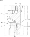
- FIG. 1 is an enlarged view of a portion where respective components of a cover assembly for a steering wheel according to one embodiment of the present invention are coupled
- FIG. 2 is a diagram illustrating a hook and a rib of a mounting plate
- FIG. 3 is a cross-sectional view taken along line A-A in FIG. 1
- FIG. 4 is a diagram illustrating a state before the mounting plate is coupled to an inner cover
- FIG. 5 is a diagram illustrating a state where the rib presses the inner cover.
- a cover assembly 1 for a steering wheel may be coupled to the steering wheel to close an inner space of the steering wheel. That is, the cover assembly 1 for a steering wheel may cover an airbag or a lighting device mounted in the inner space of the steering wheel.
- the cover assembly 1 for a steering wheel includes an outer cover 100 that is coupled to the steering wheel and covers the inner space, an inner cover 200 that is coupled to the outer cover 100 and disposed on an inner surface of the outer cover 100, and a mounting plate 300 that accommodates the airbag or the lighting device therein and is coupled to the outer cover 100 and the inner cover 200.
- the outer cover 100 may accommodate the inner cover 200 and the mounting plate 300 therein.
- the outer cover 100 may include a first cover body 120 and a first accommodation hole 140.
- the first cover body 120 may form the exterior of the outer cover 100.
- the first cover body 120 may be constituted by combination of a first side plate surrounding the inner cover 200 and the mounting plate 300, and a first cover plate covering one open side of the first side plate.
- the first accommodation hole 140 may be formed in the first side plate of the first cover body 120.
- a plurality of first accommodation holes 140 may be formed in the first side plate.
- the first accommodation hole 140 may accommodate a stopper 260 of the inner cover 200 to be described below and a support portion 280 of the mounting plate 300 to be described below.
- the inner cover 200 may be disposed on an inner surface of the first cover plate and an inner surface of the first side plate of the outer cover 100.
- the inner cover 200 may be disposed inside the outer cover 100 to emit light toward the outer cover 100.
- the inner cover 200 may include a second cover body 220, a second accommodation hole 240, and the stopper 260.
- the second cover body 220 may form the exterior of the inner cover 200.
- the second cover body 220 may be constituted by combination of a second side plate coupled to the first side plate of the first cover body 120 of the outer cover 100 and a second cover plate coupled to the first cover plate.
- the second accommodation hole 240 may be formed in the second side plate of the second cover body 220.
- a plurality of second accommodation holes 240 may be formed in the second side plate.
- the second accommodation hole 240 may be disposed in a position where the second accommodation hole 240 communicates with the first accommodation hole 140 of the outer cover 100.
- the second accommodation hole 240 may accommodate the support portion 280 of the mounting plate 300 to be described below together with the first accommodation hole 140.
- the stopper 260 may have a shape that protrudes from an outer surface of the second cover body 220 to the outside of the second cover body 220.
- the stopper 260 may pass through the first accommodation hole 140 of the outer cover 100 and protrude to the outside of the outer cover 100.
- the stopper 260 may prevent the inner cover 200 coupled to the outer cover 100 from being separated.
- the stopper 260 may block movement of a hook 340 so that the hook 340 does not descend further along a direction in which the mounting plate 300 is coupled to the inner cover 200.
- the mounting plate 300 may be accommodated inside the outer cover 100.
- the mounting plate 300 may accommodate an inflator for generating gas therein in addition to the airbag or the lighting device.
- the mounting plate 300 may include a plate body 320, the hook 340, and a rib 360.
- the plate body 320 may form the exterior of the mounting plate 300.
- the plate body 320 may be constituted by combination of a third side plate disposed adjacent to the second side plate of the inner cover 200 and a third cover plate having a shape bent from an end of the third side plate and disposed adjacent to the second cover plate of the inner cover 200.
- An open portion of the plate body 320 may be closed by the second cover plate of the inner cover 200 and the first cover plate of the outer cover 100.
- the hook 340 may be placed on an outer surface of the plate body 320. More specifically, the hook 340 may be disposed on an outer surface of the third side plate of the plate body 320. The hook 340 protrudes from the outer surface of the plate body 320 (the outer surface of the third side plate) and may have a hook shape.
- the hook 340 may penetrate the outer cover 100 and the inner cover 200 when the mounting plate 300 is coupled to the inner cover 200. More specifically, the hook 340 may pass through the first accommodation hole 140 of the outer cover 100 and the second accommodation hole 240 of the inner cover 200 and protrude to the outside of the outer cover 100. Thereby, the mounting plate 300 may be maintained in a state of being coupled to the outer cover 100 and the inner cover 200.
- the rib 360 may be disposed on the outer surface of the third side plate of the plate body 320.
- the rib 360 may be connected to the third side plate and an outer surface of the rib 360 in a state of being disposed on the outer surface of the third side plate. That is, the rib 360 may be formed integrally with the plate body 320 and the hook 340.
- the rib 360 may include an inclined surface 362.
- the inclined surface 362 may be one component of the rib 360 that is exposed to the outside of the mounting plate 300.
- the inclined surface 362 may be disposed to be inclined with respect to the plate body 320. More specifically, the rib 360 may have an inclined shape with respect to the outer surface of the third side plate of the plate body 320.
- the inclined surface 362 may have a shape in which a size of a cross-sectional area gradually decreases along a direction in which the mounting plate 300 is coupled to the inner cover 200.
- the rib 360 may form an entry space S of the hook 340 between the plate body 320 and the inner cover 200 by pressing the inner cover 200 during assembly (a process in which the mounting plate 300 is coupled to the inner cover 200).
- the inclined surface 362 of the rib 360 comes into contact with the edge of the inner cover 200 in a process in which the mounting plate 300 enters the inside of the outer cover 100.
- the inclined surface 362 of the rib 360 presses the inner cover 200 and pushes the inner cover 200 in a direction from the inner cover 200 toward the outer cover 100.
- the inclined surface 362 has a shape in which the size of the cross-sectional area gradually decreases along the direction in which the mounting plate 300 is coupled to the inner cover 200, as the mounting plate 300 enters the inside of the outer cover 100, the space (entry space S) between the inner cover 200 and the mounting plate 300 becomes increasingly wider. Accordingly, the hook 340 disposed on the outer surface of the plate body 320 enters the entry space S formed between the inner cover 200 and the mounting plate 300, and finally, the hook 340 enters the first accommodation hole 140 and the second accommodation hole 240.
- the cover assembly 1 for a steering wheel may have a structure in which the hook 340 enters the first accommodation hole 140 and the second accommodation hole 240 without damaging the inner cover 200 by the rib 360 compared to the existing structure in which the hook 340 does not enter the first accommodation hole 140 and the second accommodation hole 240 due to a phenomenon such as crushing of the end of the inner cover 200 by being pressed by the hook 340 when the mounting plate 300 enters the inside of the outer cover 100. Therefore, assembly defects may be prevented, thereby reducing defective product disposal costs and reducing assembly costs.
- the inner cover 200 may include the support portion 280.
- the support portion 280 may be formed over the inner surface of the second cover body 220 of the inner cover 200 and the stopper 260.
- the support portion 280 may be disposed to be inclined with respect to the inner surface of the second cover body 220.
- the support portion 280 may support the inclined surface 362 of the mounting plate 300 when the hook 340 is coupled to the outer cover 100 and the inner cover 200 through the entry space S.
- the support portion 280 may be disposed parallel to the inclined surface 362.
- the outer surface of the plate body 320 of the mounting plate 300 may come into contact with the inner surface of the inner cover 200. That is, as illustrated in FIG. 3 , since the rib 360 prevents a space from being formed between the inner cover 200 and the mounting plate 300 in a state where the inner cover 200 and the mounting plate 300 are coupled, shaking of the mounting plate 300 may be prevented, thereby securing the stability of the the cover assembly 1 for a steering wheel, and noise caused by the shaking of the mounting plate 300 may be prevented, thereby securing quietness.
- FIG. 6 is a diagram illustrating a rib according to another embodiment.
- a rib 360 may be detachably disposed on a plate body 320 and a hook 340. That is, the rib 360 may be provided separately from the plate body 320 and the hook 340.
- a coupling protrusion may be formed on the rib 360 and a coupling groove for accommodating the coupling protrusion may be formed on the plate body 320 and the hook 340, so that the coupling protrusion is accommodated in the coupling groove, thereby coupling the rib 360 to the plate body 320 and the hook 340.
- the rib 360 may be provided with an inclined surface 362 having various angles that is able to press an inner cover 200. Therefore, the shape of the rib 360 may be appropriately modified according to the shape of a mounting plate 300 or the inner cover 200, which is disposed inside the steering wheel and has a different shape.
- a rib disposed below a hook presses an inner cover and thus a space for the hook to enter is formed between the inner cover and a mounting plate, occurrence of defective products that are likely to occur when the hook presses the inner cover can be prevented.
Landscapes
- Engineering & Computer Science (AREA)
- Mechanical Engineering (AREA)
- Chemical & Material Sciences (AREA)
- Combustion & Propulsion (AREA)
- Transportation (AREA)
- Air Bags (AREA)
- Steering Controls (AREA)
Abstract
Description
- This application claims priority to and the benefit of
Korean Patent Application No. 10-2023-0078036, filed on 19 June, 2023 - The present invention relates to a mounting plate and a cover assembly for a steering wheel including the same.
- In general, a steering wheel, which is responsible for steering a vehicle, may be equipped with an airbag that deploys toward a driver when a vehicle collision accident occurs, a horn device that honks a horn, or a lighting device that illuminates an emblem disposed on the steering wheel.
- Therefore, a hole having an accommodation space may be formed in the steering wheel to accommodate various devices inside the steering wheel, and a cover assembly may be coupled to the steering wheel to cover the hole formed in the steering wheel.
- The cover assembly coupled to the steering wheel may include an outer cover that closes a cover of the steering wheel and whose outer surface is exposed toward a passenger compartment, an inner cover that is disposed inside the outer cover and emits light to illuminate the emblem disposed on the outer cover, and a mounting plate that is coupled to the inner cover and accommodates an airbag or a lighting device therein.
- Here, the mounting plate may be a component coupled to the inner cover by entering the inside of the outer cover after the inner cover is coupled to the outer cover, and thereby, a hook disposed on an outer surface of the mounting plate may be fixed to the outer cover and the inner cover by passing through a hole formed in the outer cover and the inner cover.
- However, a cover assembly in the related art has a problem in that damage such as crushing of the inner cover occurs due to a phenomenon in which the hook presses the inner cover as the mounting plate enters the inside of the outer cover, and thus a defective product is produced. Therefore, there is a need for structural improvement so that the hook of the mounting plate does not directly press the inner cover.
- The present invention is directed to providing a mounting plate improved so that a hook of the mounting plate does not directly press an inner cover and a cover assembly for a steering wheel including the same.
- According to an aspect of the present invention, there is provided a mounting plate accommodating an airbag or a lighting device and coupled to an outer cover and an inner cover of a cover assembly for a steering wheel, the mounting plate including a plate body provided to form an exterior of the mounting plate, a hook configured to protrude from an outer surface of the plate body to penetrate the outer cover and the inner cover, and a rib configured to form an entry space for the hook to enter between the plate body and the inner cover by pressing the inner cover during assembly.
- The rib may be inclined with respect to the plate body and wherein the rib includes an inclined surface contacting an edge of the inner cover.
- The inclined surface may have a shape in which a size of a cross-sectional area of the shape gradually decreases along a direction in which the mounting plate is coupled to the inner cover.
- The rib may be formed integrally with the plate body and the hook.
- The rib may be detachably disposed on the plate body and the hook.
- According to another aspect of the present invention, there is provided a cover assembly for a steering wheel configured to cover an airbag or a lighting device mounted in an inner space of the steering wheel, the cover assembly including an outer cover coupled to the steering wheel and covering the inner space of the steering wheel, an inner cover coupled to the outer cover and disposed on an inner surface of the outer cover, and a mounting plate accommodating the airbag or the lighting device therein and coupled to the outer cover and the inner cover, wherein the mounting plate includes a plate body provided to form an exterior of the mounting plate, a hook configured to protrude from an outer surface of the plate body to penetrate the outer cover and the inner cover, and a rib configured to form an entry space of the hook between the plate body and the inner cover by pressing the inner cover during assembly.
- The rib may be inclined with respect to the plate body and include an inclined surface contacting an edge of the inner cover.
- The inclined surface may have a shape in which a size of a cross-sectional area of the shape gradually decreases along a direction in which the mounting plate is coupled to the inner cover.
- The inner cover may include a support portion disposed parallel to the inclined surface and configured to support the inclined surface when the hook is coupled to the outer cover and the inner cover through the entry space.
- The outer surface of the plate body of the mounting plate may come into contact with an inner surface of the inner cover when the inclined surface of the rib comes into contact with the support portion.
- The above and other objects, features and advantages of the present invention will become more apparent to those of ordinary skill in the art by describing exemplary embodiments thereof in detail with reference to the accompanying drawings, in which:
-
FIG. 1 is an enlarged view of a portion where respective components of a cover assembly for a steering wheel according to one embodiment of the present invention are coupled; -
FIG. 2 is a diagram illustrating a hook and a rib of a mounting plate; -
FIG. 3 is a cross-sectional view taken along line A-A inFIG. 1 ; -
FIG. 4 is a diagram illustrating a state before the mounting plate is coupled to an inner cover; -
FIG. 5 is a diagram illustrating a state where the rib presses the inner cover; and -
FIG. 6 is a diagram illustrating a rib according to another embodiment. - Since the present invention may be variously modified and embodied, particular embodiments thereof will be illustrated in the drawings and described. However, this is not intended to limit the present invention to the specific embodiments, and it should be understood to include all modifications, equivalents, and substitutes included in the spirit and scope of the present invention.
- Although the terms including ordinal numbers such as first, second, or the like, may be used to describe various elements, these elements are not limited by these terms. These terms are only used to distinguish one element from another element. For example, without departing from the scope of the present invention, a second element could be called a first element, and similarly, a first element could be called a second element. The term "and/or" includes a combination of a plurality of related listed items or any of a plurality of related listed items.
- It will be understood that when an element is referred to as being "coupled" or "connected" to another element, the element may be directly coupled or connected to the other element, or intervening elements may also be present. In contrast, it will be understood that when an element is referred to as being "directly coupled" or "directly connected" to another element, there are not intervening elements present.
- In the description of embodiments, when one element is described as being formed "on" or "under" another element, "on" or "under" includes both a case in which the two elements are directly in contact with each other and a case in which at least one additional element is formed to be disposed between the two elements (indirectly). Further, when expressed as "on or under", the expression may include the meaning of not only an upward direction but also a downward direction based on one element.
- The terms used in the present application are merely provided to describe specific embodiments, and are not intended to limit the present invention. The singular forms are intended to include the plural forms as well, unless the context clearly indicates otherwise. In the present application, it will be further understood that the terms "includes" and/or "have", when used in this specification, specify the presence of stated features, integers, steps, operations, elements, components, and/or combinations thereof, but do not preclude the possibility of the presence or addition of one or more other features, integers, steps, operations, elements, components, or combinations thereof.
- Unless otherwise defined, all terms used herein, including technical or scientific terms, have the same meaning as commonly understood by those of ordinary skill in the art to which the present invention belongs. Terms, such as those defined in commonly used dictionaries, should be interpreted as having a meaning that is consistent with their meaning in the context of the related art and will not be interpreted in an idealized or overly formal sense unless expressly so defined herein.
- Hereinafter, a mounting plate and a cover assembly for a steering wheel including the same will be described in detail with reference to the accompanying drawings, but identical or corresponding components are denoted by the same reference numerals regardless of figure numbers, and redundant descriptions thereof will be omitted.
-
FIG. 1 is an enlarged view of a portion where respective components of a cover assembly for a steering wheel according to one embodiment of the present invention are coupled,FIG. 2 is a diagram illustrating a hook and a rib of a mounting plate,FIG. 3 is a cross-sectional view taken along line A-A inFIG. 1 ,FIG. 4 is a diagram illustrating a state before the mounting plate is coupled to an inner cover, andFIG. 5 is a diagram illustrating a state where the rib presses the inner cover. - Referring to
FIGS. 1 to 5 , acover assembly 1 for a steering wheel according to one embodiment of the present invention may be coupled to the steering wheel to close an inner space of the steering wheel. That is, thecover assembly 1 for a steering wheel may cover an airbag or a lighting device mounted in the inner space of the steering wheel. Thecover assembly 1 for a steering wheel includes anouter cover 100 that is coupled to the steering wheel and covers the inner space, aninner cover 200 that is coupled to theouter cover 100 and disposed on an inner surface of theouter cover 100, and amounting plate 300 that accommodates the airbag or the lighting device therein and is coupled to theouter cover 100 and theinner cover 200. - The
outer cover 100 may accommodate theinner cover 200 and themounting plate 300 therein. Theouter cover 100 may include afirst cover body 120 and afirst accommodation hole 140. - The
first cover body 120 may form the exterior of theouter cover 100. Thefirst cover body 120 may be constituted by combination of a first side plate surrounding theinner cover 200 and themounting plate 300, and a first cover plate covering one open side of the first side plate. - The
first accommodation hole 140 may be formed in the first side plate of thefirst cover body 120. A plurality offirst accommodation holes 140 may be formed in the first side plate. Thefirst accommodation hole 140 may accommodate astopper 260 of theinner cover 200 to be described below and asupport portion 280 of themounting plate 300 to be described below. - The
inner cover 200 may be disposed on an inner surface of the first cover plate and an inner surface of the first side plate of theouter cover 100. Theinner cover 200 may be disposed inside theouter cover 100 to emit light toward theouter cover 100. Theinner cover 200 may include asecond cover body 220, asecond accommodation hole 240, and thestopper 260. - The
second cover body 220 may form the exterior of theinner cover 200. Thesecond cover body 220 may be constituted by combination of a second side plate coupled to the first side plate of thefirst cover body 120 of theouter cover 100 and a second cover plate coupled to the first cover plate. - The
second accommodation hole 240 may be formed in the second side plate of thesecond cover body 220. A plurality of second accommodation holes 240 may be formed in the second side plate. When theinner cover 200 is coupled to theouter cover 100, thesecond accommodation hole 240 may be disposed in a position where thesecond accommodation hole 240 communicates with thefirst accommodation hole 140 of theouter cover 100. Thesecond accommodation hole 240 may accommodate thesupport portion 280 of the mountingplate 300 to be described below together with thefirst accommodation hole 140. - The
stopper 260 may have a shape that protrudes from an outer surface of thesecond cover body 220 to the outside of thesecond cover body 220. When theinner cover 200 is coupled to theouter cover 100, thestopper 260 may pass through thefirst accommodation hole 140 of theouter cover 100 and protrude to the outside of theouter cover 100. Thestopper 260 may prevent theinner cover 200 coupled to theouter cover 100 from being separated. In addition, when the mountingplate 300 is coupled to theinner cover 200, thestopper 260 may block movement of ahook 340 so that thehook 340 does not descend further along a direction in which the mountingplate 300 is coupled to theinner cover 200. - The mounting
plate 300 may be accommodated inside theouter cover 100. The mountingplate 300 may accommodate an inflator for generating gas therein in addition to the airbag or the lighting device. The mountingplate 300 may include aplate body 320, thehook 340, and arib 360. - The
plate body 320 may form the exterior of the mountingplate 300. Theplate body 320 may be constituted by combination of a third side plate disposed adjacent to the second side plate of theinner cover 200 and a third cover plate having a shape bent from an end of the third side plate and disposed adjacent to the second cover plate of theinner cover 200. An open portion of theplate body 320 may be closed by the second cover plate of theinner cover 200 and the first cover plate of theouter cover 100. - The
hook 340 may be placed on an outer surface of theplate body 320. More specifically, thehook 340 may be disposed on an outer surface of the third side plate of theplate body 320. Thehook 340 protrudes from the outer surface of the plate body 320 (the outer surface of the third side plate) and may have a hook shape. - The
hook 340 may penetrate theouter cover 100 and theinner cover 200 when the mountingplate 300 is coupled to theinner cover 200. More specifically, thehook 340 may pass through thefirst accommodation hole 140 of theouter cover 100 and thesecond accommodation hole 240 of theinner cover 200 and protrude to the outside of theouter cover 100. Thereby, the mountingplate 300 may be maintained in a state of being coupled to theouter cover 100 and theinner cover 200. - The
rib 360 may be disposed on the outer surface of the third side plate of theplate body 320. Therib 360 may be connected to the third side plate and an outer surface of therib 360 in a state of being disposed on the outer surface of the third side plate. That is, therib 360 may be formed integrally with theplate body 320 and thehook 340. - The
rib 360 may include aninclined surface 362. Theinclined surface 362 may be one component of therib 360 that is exposed to the outside of the mountingplate 300. Theinclined surface 362 may be disposed to be inclined with respect to theplate body 320. More specifically, therib 360 may have an inclined shape with respect to the outer surface of the third side plate of theplate body 320. Theinclined surface 362 may have a shape in which a size of a cross-sectional area gradually decreases along a direction in which the mountingplate 300 is coupled to theinner cover 200. - In the following, a process in which the
hook 340 is disposed in thefirst accommodation hole 140 and thesecond accommodation hole 240 through theinclined surface 362 will be described. - Referring back to
FIGS. 3 to 5 , therib 360 may form an entry space S of thehook 340 between theplate body 320 and theinner cover 200 by pressing theinner cover 200 during assembly (a process in which the mountingplate 300 is coupled to the inner cover 200). As illustrated inFIG. 3 , theinclined surface 362 of therib 360 comes into contact with the edge of theinner cover 200 in a process in which the mountingplate 300 enters the inside of theouter cover 100. Thereby, as in the process of moving fromFIG. 4 to FIG. 5 , theinclined surface 362 of therib 360 presses theinner cover 200 and pushes theinner cover 200 in a direction from theinner cover 200 toward theouter cover 100. - In this case, since the
inclined surface 362 has a shape in which the size of the cross-sectional area gradually decreases along the direction in which the mountingplate 300 is coupled to theinner cover 200, as the mountingplate 300 enters the inside of theouter cover 100, the space (entry space S) between theinner cover 200 and the mountingplate 300 becomes increasingly wider. Accordingly, thehook 340 disposed on the outer surface of theplate body 320 enters the entry space S formed between theinner cover 200 and the mountingplate 300, and finally, thehook 340 enters thefirst accommodation hole 140 and thesecond accommodation hole 240. - In this way, the
cover assembly 1 for a steering wheel according to one embodiment of the present invention may have a structure in which thehook 340 enters thefirst accommodation hole 140 and thesecond accommodation hole 240 without damaging theinner cover 200 by therib 360 compared to the existing structure in which thehook 340 does not enter thefirst accommodation hole 140 and thesecond accommodation hole 240 due to a phenomenon such as crushing of the end of theinner cover 200 by being pressed by thehook 340 when the mountingplate 300 enters the inside of theouter cover 100. Therefore, assembly defects may be prevented, thereby reducing defective product disposal costs and reducing assembly costs. - Meanwhile, the
inner cover 200 may include thesupport portion 280. Thesupport portion 280 may be formed over the inner surface of thesecond cover body 220 of theinner cover 200 and thestopper 260. Thesupport portion 280 may be disposed to be inclined with respect to the inner surface of thesecond cover body 220. Thesupport portion 280 may support theinclined surface 362 of the mountingplate 300 when thehook 340 is coupled to theouter cover 100 and theinner cover 200 through the entry space S. In this case, thesupport portion 280 may be disposed parallel to theinclined surface 362. - Thereby, when the
inclined surface 362 of therib 360 comes into contact with thesupport portion 280, the outer surface of theplate body 320 of the mountingplate 300 may come into contact with the inner surface of theinner cover 200. That is, as illustrated inFIG. 3 , since therib 360 prevents a space from being formed between theinner cover 200 and the mountingplate 300 in a state where theinner cover 200 and the mountingplate 300 are coupled, shaking of the mountingplate 300 may be prevented, thereby securing the stability of the thecover assembly 1 for a steering wheel, and noise caused by the shaking of the mountingplate 300 may be prevented, thereby securing quietness. -
FIG. 6 is a diagram illustrating a rib according to another embodiment. - Referring to
FIG. 6 , arib 360 may be detachably disposed on aplate body 320 and ahook 340. That is, therib 360 may be provided separately from theplate body 320 and thehook 340. For example, a coupling protrusion may be formed on therib 360 and a coupling groove for accommodating the coupling protrusion may be formed on theplate body 320 and thehook 340, so that the coupling protrusion is accommodated in the coupling groove, thereby coupling therib 360 to theplate body 320 and thehook 340. - Accordingly, the
rib 360 may be provided with aninclined surface 362 having various angles that is able to press aninner cover 200. Therefore, the shape of therib 360 may be appropriately modified according to the shape of a mountingplate 300 or theinner cover 200, which is disposed inside the steering wheel and has a different shape. - According to one embodiment of the present invention, since a rib disposed below a hook presses an inner cover and thus a space for the hook to enter is formed between the inner cover and a mounting plate, occurrence of defective products that are likely to occur when the hook presses the inner cover can be prevented.
- Although the embodiments of the present invention have been described above, it is understood that one ordinary skilled in the art can make various changes and modifications to the present invention without departing from the spirit and scope of the present invention as hereinafter claimed. Further, it should be construed that differences associated with such changes and modifications fall within the scope of the present invention defined by the accompanying claims.
Claims (10)
- A mounting plate accommodating an airbag or a lighting device therein and coupled to an outer cover and an inner cover of a cover assembly for a steering wheel, the mounting plate comprising:a plate body provided to form an exterior of the mounting plate;a hook configured to protrude from an outer surface of the plate body to penetrate the outer cover and the inner cover; anda rib configured to form an entry space for the hook to enter between the plate body and the inner cover by pressing the inner cover during assembly.
- The mounting plate of claim 1, wherein the rib is inclined with respect to the plate body, and wherein the rib includes an inclined surface contacting an edge of the inner cover.
- The mounting plate of claim 2, wherein the inclined surface has a shape in which a size of a cross-sectional area of the shape gradually decreases along a direction in which the mounting plate is coupled to the inner cover.
- The mounting plate of any one of claims 1 to 3, wherein the rib is formed integrally with the plate body and the hook.
- The mounting plate of any one of claims 1 to 4, wherein the rib is detachably disposed on the plate body and the hook.
- A cover assembly for a steering wheel configured to cover an airbag or a lighting device mounted in an inner space of the steering wheel, the cover assembly comprising:an outer cover coupled to the steering wheel and covering the inner space of the steering wheel;an inner cover coupled to the outer cover and disposed on an inner surface of the outer cover; anda mounting plate accommodating the airbag or the lighting device therein and coupled to the outer cover and the inner cover,wherein the mounting plate includes:a plate body provided to form an exterior of the mounting plate;a hook configured to protrude from an outer surface of the plate body to penetrate the outer cover and the inner cover; anda rib configured to form an entry space of the hook between the plate body and the inner cover by pressing the inner cover during assembly.
- The cover assembly of claim 6, wherein the rib is inclined with respect to the plate body and includes an inclined surface contacting an edge of the inner cover during the assembly.
- The cover assembly of claim 7, wherein the inclined surface has a shape in which a size of a cross-sectional area of the shape gradually decreases along a direction in which the mounting plate is coupled to the inner cover.
- The cover assembly of claim 7 or 8, wherein the inner cover includes a support portion disposed parallel to the inclined surface and configured to support the inclined surface when the hook is coupled to the outer cover and the inner cover through the entry space.
- The cover assembly of claim 9, wherein the outer surface of the plate body of the mounting plate comes into contact with an inner surface of the inner cover when the inclined surface of the rib comes into contact with the support portion.
Applications Claiming Priority (1)
| Application Number | Priority Date | Filing Date | Title |
|---|---|---|---|
| KR1020230078036A KR20240177060A (en) | 2023-06-19 | 2023-06-19 | Mounting plate and cover assembly for steering wheel comprising the same |
Publications (2)
| Publication Number | Publication Date |
|---|---|
| EP4480759A1 true EP4480759A1 (en) | 2024-12-25 |
| EP4480759B1 EP4480759B1 (en) | 2025-11-26 |
Family
ID=89073028
Family Applications (1)
| Application Number | Title | Priority Date | Filing Date |
|---|---|---|---|
| EP23213729.9A Active EP4480759B1 (en) | 2023-06-19 | 2023-12-01 | Mounting plate and cover assembly for steering wheel including the same |
Country Status (4)
| Country | Link |
|---|---|
| US (1) | US12311862B2 (en) |
| EP (1) | EP4480759B1 (en) |
| KR (1) | KR20240177060A (en) |
| CN (1) | CN221251413U (en) |
Families Citing this family (1)
| Publication number | Priority date | Publication date | Assignee | Title |
|---|---|---|---|---|
| KR20250168822A (en) * | 2024-05-24 | 2025-12-02 | 현대모비스 주식회사 | Airbag cover assembly |
Citations (2)
| Publication number | Priority date | Publication date | Assignee | Title |
|---|---|---|---|---|
| US20220063518A1 (en) * | 2020-09-01 | 2022-03-03 | Hyundai Mobis Co., Ltd. | Driver airbag with emblem |
| KR20230078036A (en) | 2021-11-26 | 2023-06-02 | 현대종합금속 주식회사 | Self-Shielded Flux Cored Wire for Welding of Austenite Stainless Steel |
Family Cites Families (4)
| Publication number | Priority date | Publication date | Assignee | Title |
|---|---|---|---|---|
| JP3003578B2 (en) * | 1996-07-22 | 2000-01-31 | 株式会社デンソー | Casing for airbag device of vehicle and cover member therefor |
| JP5005019B2 (en) * | 2009-11-23 | 2012-08-22 | 本田技研工業株式会社 | Steering wheel |
| US11414038B2 (en) * | 2018-10-29 | 2022-08-16 | Autoliv Development Ab | Steering wheel with vibration damping mass |
| KR102761183B1 (en) * | 2020-04-10 | 2025-01-31 | 현대모비스 주식회사 | Driver seat airbag |
-
2023
- 2023-06-19 KR KR1020230078036A patent/KR20240177060A/en active Pending
- 2023-11-27 US US18/519,255 patent/US12311862B2/en active Active
- 2023-12-01 EP EP23213729.9A patent/EP4480759B1/en active Active
- 2023-12-21 CN CN202323504970.9U patent/CN221251413U/en active Active
Patent Citations (2)
| Publication number | Priority date | Publication date | Assignee | Title |
|---|---|---|---|---|
| US20220063518A1 (en) * | 2020-09-01 | 2022-03-03 | Hyundai Mobis Co., Ltd. | Driver airbag with emblem |
| KR20230078036A (en) | 2021-11-26 | 2023-06-02 | 현대종합금속 주식회사 | Self-Shielded Flux Cored Wire for Welding of Austenite Stainless Steel |
Also Published As
| Publication number | Publication date |
|---|---|
| KR20240177060A (en) | 2024-12-27 |
| US20240416860A1 (en) | 2024-12-19 |
| CN221251413U (en) | 2024-07-02 |
| EP4480759B1 (en) | 2025-11-26 |
| US12311862B2 (en) | 2025-05-27 |
Similar Documents
| Publication | Publication Date | Title |
|---|---|---|
| US10479312B2 (en) | Side air bag device | |
| US11305718B2 (en) | Driver airbag module with lighting device | |
| KR20220029124A (en) | Driver's airbag with emblem | |
| US11214221B2 (en) | Hard cover for side airbag | |
| EP4480759A1 (en) | Mounting plate and cover assembly for steering wheel including the same | |
| KR100288087B1 (en) | Passenger seat airbag device | |
| US20050275197A1 (en) | Airbag cover and airbag system | |
| KR100503294B1 (en) | Passenger airbag module for a motor vehicle | |
| CN111301335A (en) | Decorative member and cover body of airbag device | |
| US8240704B2 (en) | Pad cover fastening structure | |
| US20240149821A1 (en) | Steering wheel | |
| JP2002114121A (en) | Air bag device | |
| JP3898856B2 (en) | Airbag module | |
| US20140232090A1 (en) | Airbag device for vehicle | |
| JP2015024699A (en) | Air bag device | |
| US20050110252A1 (en) | Air-bag door structure | |
| JP3895896B2 (en) | Airbag module | |
| CN110949305B (en) | front body structure | |
| JPWO2013011981A1 (en) | Steering wheel unit | |
| JPH06298032A (en) | Airbag device for front passenger seat | |
| KR20260026187A (en) | Airbag housing for vehicle | |
| KR100698683B1 (en) | Assembly structure of airbag housing and airbag door | |
| KR20240148121A (en) | Air bag cover | |
| JPH09267708A (en) | Car interior side member structure having air bag door section integrally | |
| US10457242B2 (en) | Air bag device |
Legal Events
| Date | Code | Title | Description |
|---|---|---|---|
| PUAI | Public reference made under article 153(3) epc to a published international application that has entered the european phase |
Free format text: ORIGINAL CODE: 0009012 |
|
| STAA | Information on the status of an ep patent application or granted ep patent |
Free format text: STATUS: THE APPLICATION HAS BEEN PUBLISHED |
|
| AK | Designated contracting states |
Kind code of ref document: A1 Designated state(s): AL AT BE BG CH CY CZ DE DK EE ES FI FR GB GR HR HU IE IS IT LI LT LU LV MC ME MK MT NL NO PL PT RO RS SE SI SK SM TR |
|
| STAA | Information on the status of an ep patent application or granted ep patent |
Free format text: STATUS: REQUEST FOR EXAMINATION WAS MADE |
|
| 17P | Request for examination filed |
Effective date: 20250520 |
|
| GRAP | Despatch of communication of intention to grant a patent |
Free format text: ORIGINAL CODE: EPIDOSNIGR1 |
|
| STAA | Information on the status of an ep patent application or granted ep patent |
Free format text: STATUS: GRANT OF PATENT IS INTENDED |
|
| RIC1 | Information provided on ipc code assigned before grant |
Ipc: B60R 21/203 20060101AFI20250604BHEP |
|
| INTG | Intention to grant announced |
Effective date: 20250626 |
|
| P01 | Opt-out of the competence of the unified patent court (upc) registered |
Free format text: CASE NUMBER: UPC_APP_5622_4480759/2025 Effective date: 20250902 |
|
| GRAS | Grant fee paid |
Free format text: ORIGINAL CODE: EPIDOSNIGR3 |
|
| GRAA | (expected) grant |
Free format text: ORIGINAL CODE: 0009210 |
|
| STAA | Information on the status of an ep patent application or granted ep patent |
Free format text: STATUS: THE PATENT HAS BEEN GRANTED |
|
| AK | Designated contracting states |
Kind code of ref document: B1 Designated state(s): AL AT BE BG CH CY CZ DE DK EE ES FI FR GB GR HR HU IE IS IT LI LT LU LV MC ME MK MT NL NO PL PT RO RS SE SI SK SM TR |
|
| REG | Reference to a national code |
Ref country code: CH Ref legal event code: F10 Free format text: ST27 STATUS EVENT CODE: U-0-0-F10-F00 (AS PROVIDED BY THE NATIONAL OFFICE) Effective date: 20251126 Ref country code: GB Ref legal event code: FG4D |
|
| REG | Reference to a national code |
Ref country code: IE Ref legal event code: FG4D |
|
| REG | Reference to a national code |
Ref country code: DE Ref legal event code: R096 Ref document number: 602023008989 Country of ref document: DE |
|
| PGFP | Annual fee paid to national office [announced via postgrant information from national office to epo] |
Ref country code: AT Payment date: 20260113 Year of fee payment: 3 |
|
| REG | Reference to a national code |
Ref country code: NL Ref legal event code: MP Effective date: 20251126 |
|
| PG25 | Lapsed in a contracting state [announced via postgrant information from national office to epo] |
Ref country code: ES Free format text: LAPSE BECAUSE OF FAILURE TO SUBMIT A TRANSLATION OF THE DESCRIPTION OR TO PAY THE FEE WITHIN THE PRESCRIBED TIME-LIMIT Effective date: 20251126 |
|
| REG | Reference to a national code |
Ref country code: LT Ref legal event code: MG9D |
|
| PG25 | Lapsed in a contracting state [announced via postgrant information from national office to epo] |
Ref country code: NO Free format text: LAPSE BECAUSE OF FAILURE TO SUBMIT A TRANSLATION OF THE DESCRIPTION OR TO PAY THE FEE WITHIN THE PRESCRIBED TIME-LIMIT Effective date: 20260226 |
|
| PGFP | Annual fee paid to national office [announced via postgrant information from national office to epo] |
Ref country code: DE Payment date: 20260120 Year of fee payment: 3 |
|
| PG25 | Lapsed in a contracting state [announced via postgrant information from national office to epo] |
Ref country code: FI Free format text: LAPSE BECAUSE OF FAILURE TO SUBMIT A TRANSLATION OF THE DESCRIPTION OR TO PAY THE FEE WITHIN THE PRESCRIBED TIME-LIMIT Effective date: 20251126 Ref country code: HR Free format text: LAPSE BECAUSE OF FAILURE TO SUBMIT A TRANSLATION OF THE DESCRIPTION OR TO PAY THE FEE WITHIN THE PRESCRIBED TIME-LIMIT Effective date: 20251126 Ref country code: AT Free format text: LAPSE BECAUSE OF FAILURE TO SUBMIT A TRANSLATION OF THE DESCRIPTION OR TO PAY THE FEE WITHIN THE PRESCRIBED TIME-LIMIT Effective date: 20251126 |
|
| REG | Reference to a national code |
Ref country code: AT Ref legal event code: MK05 Ref document number: 1860788 Country of ref document: AT Kind code of ref document: T Effective date: 20251126 |
|
| PG25 | Lapsed in a contracting state [announced via postgrant information from national office to epo] |
Ref country code: NL Free format text: LAPSE BECAUSE OF FAILURE TO SUBMIT A TRANSLATION OF THE DESCRIPTION OR TO PAY THE FEE WITHIN THE PRESCRIBED TIME-LIMIT Effective date: 20251126 |
|
| PG25 | Lapsed in a contracting state [announced via postgrant information from national office to epo] |
Ref country code: RS Free format text: LAPSE BECAUSE OF FAILURE TO SUBMIT A TRANSLATION OF THE DESCRIPTION OR TO PAY THE FEE WITHIN THE PRESCRIBED TIME-LIMIT Effective date: 20260226 |
|
| PG25 | Lapsed in a contracting state [announced via postgrant information from national office to epo] |
Ref country code: IS Free format text: LAPSE BECAUSE OF FAILURE TO SUBMIT A TRANSLATION OF THE DESCRIPTION OR TO PAY THE FEE WITHIN THE PRESCRIBED TIME-LIMIT Effective date: 20260326 |
|
| PGFP | Annual fee paid to national office [announced via postgrant information from national office to epo] |
Ref country code: FR Payment date: 20260107 Year of fee payment: 3 |
|
| PG25 | Lapsed in a contracting state [announced via postgrant information from national office to epo] |
Ref country code: PT Free format text: LAPSE BECAUSE OF FAILURE TO SUBMIT A TRANSLATION OF THE DESCRIPTION OR TO PAY THE FEE WITHIN THE PRESCRIBED TIME-LIMIT Effective date: 20260326 |
|
| PG25 | Lapsed in a contracting state [announced via postgrant information from national office to epo] |
Ref country code: PL Free format text: LAPSE BECAUSE OF FAILURE TO SUBMIT A TRANSLATION OF THE DESCRIPTION OR TO PAY THE FEE WITHIN THE PRESCRIBED TIME-LIMIT Effective date: 20251126 |
|
| PG25 | Lapsed in a contracting state [announced via postgrant information from national office to epo] |
Ref country code: LV Free format text: LAPSE BECAUSE OF FAILURE TO SUBMIT A TRANSLATION OF THE DESCRIPTION OR TO PAY THE FEE WITHIN THE PRESCRIBED TIME-LIMIT Effective date: 20251126 |