EP4480755A1 - Vehicle front part structure - Google Patents
Vehicle front part structure Download PDFInfo
- Publication number
- EP4480755A1 EP4480755A1 EP24179455.1A EP24179455A EP4480755A1 EP 4480755 A1 EP4480755 A1 EP 4480755A1 EP 24179455 A EP24179455 A EP 24179455A EP 4480755 A1 EP4480755 A1 EP 4480755A1
- Authority
- EP
- European Patent Office
- Prior art keywords
- vehicle
- raised wall
- opening
- communication
- front part
- Prior art date
- Legal status (The legal status is an assumption and is not a legal conclusion. Google has not performed a legal analysis and makes no representation as to the accuracy of the status listed.)
- Pending
Links
Images


Classifications
-
- B—PERFORMING OPERATIONS; TRANSPORTING
- B60—VEHICLES IN GENERAL
- B60R—VEHICLES, VEHICLE FITTINGS, OR VEHICLE PARTS, NOT OTHERWISE PROVIDED FOR
- B60R7/00—Stowing or holding appliances inside vehicle primarily intended for personal property smaller than suit-cases, e.g. travelling articles, or maps
- B60R7/04—Stowing or holding appliances inside vehicle primarily intended for personal property smaller than suit-cases, e.g. travelling articles, or maps in driver or passenger space, e.g. using racks
- B60R7/06—Stowing or holding appliances inside vehicle primarily intended for personal property smaller than suit-cases, e.g. travelling articles, or maps in driver or passenger space, e.g. using racks mounted on or below dashboards
-
- B—PERFORMING OPERATIONS; TRANSPORTING
- B62—LAND VEHICLES FOR TRAVELLING OTHERWISE THAN ON RAILS
- B62D—MOTOR VEHICLES; TRAILERS
- B62D25/00—Superstructure or monocoque structure sub-units; Parts or details thereof not otherwise provided for
- B62D25/08—Front or rear portions
-
- B—PERFORMING OPERATIONS; TRANSPORTING
- B60—VEHICLES IN GENERAL
- B60R—VEHICLES, VEHICLE FITTINGS, OR VEHICLE PARTS, NOT OTHERWISE PROVIDED FOR
- B60R5/00—Compartments within vehicle body primarily intended or sufficiently spacious for trunks, suit-cases, or the like
- B60R5/02—Compartments within vehicle body primarily intended or sufficiently spacious for trunks, suit-cases, or the like arranged at front of vehicle
-
- B—PERFORMING OPERATIONS; TRANSPORTING
- B62—LAND VEHICLES FOR TRAVELLING OTHERWISE THAN ON RAILS
- B62D—MOTOR VEHICLES; TRAILERS
- B62D25/00—Superstructure or monocoque structure sub-units; Parts or details thereof not otherwise provided for
- B62D25/08—Front or rear portions
- B62D25/087—Luggage compartments
Definitions
- the present invention relates to a vehicle front part structure.
- Patent Literature 1 discloses a vehicle provided with a trunk at a front part.
- Patent Literature 1 is formed of a resin material and arranged below a bonnet at the vehicle front part. A user can open the bonnet and take an object into and out of the trunk.
- Patent Literature 1 German Patent Application Publication No. 102020106560
- the present invention has been made in view of the problem as described above and aims to provide a vehicle front part structure that can prevent unintentional package movement during vehicle traveling while allowing access to a trunk from a vehicle cabin side.
- a vehicle front part structure is characterized by including a front trunk disposed at a vehicle front part on a front side of a vehicle cabin of a vehicle and having a front housing space that can house a package; a vehicle cabin side housing portion disposed at a front part of the vehicle cabin, having a vehicle cabin side housing space into and out of which a package can be taken from the vehicle cabin side, and provided with a lid that can open and close an opening of the vehicle cabin side housing space on the vehicle cabin side; a communication portion having a communication space providing communication between the front housing space and the vehicle cabin side housing space; and a movement restriction portion that is provided at the communication portion and restricts package movement in the communication space.
- the vehicle front part structure since the front trunk at the vehicle front part, the vehicle cabin side housing portion at the vehicle cabin front part, and the communication portion having the communication space providing communication between the front housing space and the vehicle cabin side housing space are provided, it is possible to ensure a housing space in which a package can be accessed from both inside and outside the vehicle cabin while enlarging housing capacity of a trunk of the vehicle.
- the movement restriction portion that restricts package movement in the communication space is provided at the communication portion, packages housed in the front trunk or the communication portion can be prevented from unintentionally moving in a front-rear direction during vehicle traveling.
- the movement restriction portion may further include a projection, protruding inside the communication space from an inner surface of the communication portion, in at least one state of the projection.
- the movement restriction portion may further comprise a raised wall that can be displaced between a closed position where movement of the package is restricted by partitioning of at least part of an opening section of the front housing space in the communication space and an opened position where the movement restriction is canceled.
- the vehicle front part structure it is possible to prevent package movement in the communication space as the raised wall at the closed position restricts package movement by partitioning at least part of an opening section of the communication space in the communication portion during vehicle traveling, and it is possible to smoothly perform package movement in the communication space as the raised wall is displaced from the closed position to the opened position to cancel the movement restriction when a package is taken into and out of the front trunk.
- the raised wall may be arranged in a front opening of the communication space, which communicates with the housing space of the front trunk.
- a lower or upper end part of the raised wall may be rotatably supported to a rotational shaft portion extending in the vehicle width direction. Accordingly, the raised wall can open and close at least part of the front opening of the communication space by swinging in the vehicle front-rear direction with the rotational shaft portion as a rotational axis.
- the raised wall may close a whole area of the opening section of the communication space in a closed state.
- the raised wall can close the whole area of the front opening but only needs to be able to close at least part, for example, lower half from a bottom surface of the front opening to restrict package movement, and in this case, the upper side of the raised wall may be opened.
- the vehicle front part structure according to the above-described aspect may further include an opening-closing operation portion that is operated to open and close the raised wall.
- an occupant of the vehicle can optionally open and close the raised wall by performing an operation to open and close the raised wall by using the opening-closing operation portion when desiring to open and close the raised wall.
- the opening-closing operation portion may comprise the lid of the vehicle cabin side housing portion, and the raised wall may be opened and closed in coordination with opening-closing operation of the lid.
- the opening-closing operation portion includes the lid of the vehicle cabin side housing portion, an operation member for performing an operation to open and close the raised wall does not need to be provided in the vehicle cabin in addition to the lid, and the configuration of the vehicle cabin front part can be simplified. Moreover, since the raised wall is opened and closed in coordination with opening-closing operation of the lid, an operation to open and close the raised wall can be easily performed.
- the raised wall can be opened in coordination with opening operation of the lid and an occupant can move the package to an optional place in the front trunk or the communication portion while visually recognizing the package.
- a link bar that extends in a longitudinal direction of the communication portion might be provided, wherein a rear end part of the link bar is coupled to the lid of the vehicle cabin side housing portion and a front end part of the link bar is coupled to an upper part of the raised wall.
- the raised wall may be opened and closed in coordination with the opening-closing operation of the lid such that when the lid is open the raised wall is open and if the lid is closed the raised wall is closed.
- the raised wall may be opened and closed in coordination with the inverse opening-closing operation of the lid such that when any one of the lid and the raised wall is open the other one is closed and vice-versa.
- the opening-closing operation portion may comprise an operation member that extends in a longitudinal direction of the communication portion and opens and closes the raised wall by moving in the longitudinal direction, and the operation member may include a coupling end part coupled to the raised wall, and an operation end part provided inside or around the vehicle cabin side housing portion.
- an occupant can easily perform an operation to open and close the raised wall only by holding the operation end part of the operation member in the vehicle cabin and operating the operation member. Moreover, it is possible to open and close the raised wall at an optional timing while maintaining a state in which the lid of the vehicle cabin side housing portion is opened, and thus an occupant in the vehicle cabin can reliably check an opened-closed state of the raised wall.
- the opening-closing operation portion is either a pulling operation lever or a pressing operation lever.
- the pressing operation lever and the pressing operation lever are an operation member that extend in the longitudinal direction of the communication portion and open and close the raised wall by moving in the longitudinal direction.
- the raised wall can be closed by own weight when the operation of pressing the pressing operation lever is stopped or when the operation of pulling the pulling operation lever is stopped.
- a lever support portion may be provided on a ceiling surface of the communication space inside the communication space so that the operation lever is freely movable back and forth in a longitudinal direction of the vehicle.
- the raised wall can open and close the whole area of the opening section of the communication space in a closed state
- the vehicle front part structure may further include a seal member that provides sealing between a periphery of the raised wall and an inner peripheral surface of the communication space in a state in which the raised wall is closed.
- the raised wall can open and close the whole area of the opening section of the communication space in a closed state, and the raised wall may partition the communication space in an airtight manner into parts on a front side and a rear side in a vehicle front-rear direction in a state in which the raised wall is closed.
- the raised wall partitions the communication space in an airtight manner into parts on the front side and the rear side, respectively, in the vehicle front-rear direction in a state in which the whole area of the opening section of the communication portion is closed by the raised wall, smell of a package housed in the front trunk or a part of the communication portion on the vehicle front side can be prevented from reaching inside the vehicle cabin through the communication space.
- noise generated by unintentional movement of a package housed in the front trunk or a part of the communication portion on the vehicle front side during vehicle traveling can be prevented from being transferred into the vehicle cabin through the communication space.
- the vehicle cabin side housing portion may be a glove box provided at an instrument panel.
- the glove box may have a front opening on the front side and a rear opening on the rear side, wherein preferably a lower end part of the lid is rotatably supported to a rotational shaft portion extending in a vehicle width direction such that the rear opening can be opened and closed by the lid.
- the glove box provided at the instrument panel is used as the vehicle cabin side housing portion, space inside the vehicle cabin can be effectively utilized. Moreover, without change of arrangement in the vehicle cabin, the front trunk can be accessed from the glove box through the communication portion to move a package.
- FR indicates a vehicle front side
- RR indicates a vehicle rear side
- RH indicates a vehicle right side
- LH indicates a vehicle left side
- UP indicates a vehicle upper side
- LO indicates a vehicle lower side.
- the vehicle 1 includes a front trunk 12 at a front part 1a on the front side of a dash panel 1c.
- the front trunk 12 is disposed below a bonnet (not illustrated) and has a space that can house a package.
- the vehicle 1 includes an instrument panel 10 in a vehicle cabin 1b on the rear side of the dash panel 1c.
- the instrument panel 10 is disposed at a front side part of the vehicle cabin 1b and extends in the right-left direction.
- the instrument panel 10 is provided with a glove box 11 at a part on the front side of a front passenger seat side part 1d.
- the glove box 11 has a configuration with which a package can be taken in and out from the vehicle cabin 1b side.
- the glove box 11 of the present embodiment corresponds to a vehicle cabin side housing portion.
- the vehicle 1 further includes a communication portion 13 connecting the front trunk 12 and the glove box 11.
- a communication portion 13 connecting the front trunk 12 and the glove box 11.
- a housing space 12a of the front trunk 12 and a housing space 11a of the glove box 11 communicate with each other through the communication portion 13.
- the vehicle 1 also includes a raised wall 21 that opens and closes an opening section of a communication space 13a of the communication portion 13, specifically, a front opening 13c that is opened on the vehicle front side in the communication space 13a, and a link bar 22 that links the raised wall 21 to opening and closing of a lid 11b of the glove box 11.
- the raised wall 21 of the present embodiment corresponds to a movement restriction portion that restricts movement between the front trunk 12 and the communication portion 13.
- connection of the front trunk 12 and the glove box 11 to the communication portion 13 will be described below with reference to FIG. 2 .
- the front trunk 12 has an opening 12b on the upper side and has a rear opening 12e on the lower side of a rear wall 12d.
- a package can be taken into and out of the housing space 12a of the front trunk 12 through the opening 12b.
- an inner bottom surface 12c of the front trunk 12 has a configuration as a substantially horizontal plane. Since the inner bottom surface 12c has a configuration as a horizontal plane, a package placed on the inner bottom surface 12c is unlikely to move to front, rear, right, and left.
- the glove box 11 has a front opening 11d on the front side and has a rear opening 11e on the rear side.
- the rear opening 11e can be opened and closed by the lid 11b.
- a lower end part of the lid 11b is rotatably supported to a rotational shaft portion 11f extending in a vehicle width direction (direction orthogonal to the sheet of FIG. 2 ). Accordingly, the lid 11b can open and close the rear opening 11e by swinging in a vehicle front-rear direction with the rotational shaft portion 11f as a rotational axis as illustrated in FIGS. 2 and 3 .
- the housing space 11a of the glove box 11 is formed between the front opening 11d and the rear opening 11e in the front-rear direction of the vehicle 1.
- An inner bottom surface 11c of the glove box 11 has a configuration as a substantially horizontal plane.
- the communication portion 13 has the communication space 13a extending in the front-rear direction and has a tubular configuration that its circumference is covered by a wall portion.
- the communication space 13a of the communication portion 13 is connected to the rear opening 12e of the housing space 12a of the front trunk 12 at the front opening 13c on the front side and connected to the front opening 11d of the housing space 11a of the glove box 11 at a rear opening 13d on the rear side.
- An inner bottom surface 13b of the communication portion 13 has a configuration as a substantially horizontal plane and has a configuration connected to each of the inner bottom surface 12c of the front trunk 12 and the inner bottom surface 11c of the glove box 11 without a step.
- the raised wall 21 serves as the movement restriction portion that is provided at the front opening 13c of the communication portion 13 to extend in the vehicle width direction (direction orthogonal to the sheets of FIGS. 2 and 3 ) and restricts package movement in the communication space 13a.
- the raised wall 21 is arranged in the communication space 13a.
- the raised wall 21 of the present embodiment is arranged in the front opening 13c of the communication space 13a, which communicates with the housing space 12a of the front trunk 12.
- a lower end part of the raised wall 21 is rotatably supported to a rotational shaft portion 23 extending in the vehicle width direction (direction orthogonal to the sheet of FIG. 2 ). Accordingly, the raised wall 21 can open and close at least part of the front opening 13c (in the present embodiment, the whole area of the front opening 13c) of the communication space 13a by swinging in the vehicle front-rear direction with the rotational shaft portion 23 as a rotational axis.
- the raised wall 21 can close the whole area of the front opening 13c but only needs to be able to close at least part, for example, lower half from a bottom surface of the front opening 13c to restrict package movement, and in this case, the upper side of the raised wall 21 may be opened.
- a seal member 27 (refer to FIGS. 4 to 6 ) to be described later may be provided at either the periphery of the raised wall 21 or the periphery of the front opening 13c of the communication space 13a.
- smell of a package housed in the front trunk 12 can be prevented from reaching the glove box 11 on the vehicle cabin side through the communication space 13a.
- noise generated by unintentional package movement in the front trunk 12 during vehicle traveling can be prevented from reaching the glove box 11 on the vehicle cabin side through the communication space 13a.
- the vehicle front part structure of the present embodiment includes an opening-closing operation portion that is operated to open and close the raised wall 21.
- the opening-closing operation portion is constituted by the lid 11b of the glove box 11 and the link bar 22 that links and connects the lid 11b and the raised wall 21.
- the link bar 22 extends in a longitudinal direction of the communication portion 13 inside or outside the communication space 13a of the communication portion 13.
- a rear end part 22a of the link bar 22 is rotatably coupled to an upper part of the lid 11b of the glove box 11.
- a front end part 22b of the link bar 22 is rotatably coupled to an upper part of the raised wall 21.
- the raised wall 21 is linked and connected to the lid 11b through the link bar 22 and thus can open and close in coordination with opening-closing operation of the lid 11b.
- the upper part of the raised wall 21 is pulled toward the vehicle rear side by the link bar 22 so that the raised wall 21 can open while inclining to the vehicle rear side.
- the lid 11b is closed, the upper part of the raised wall 21 is pressed toward the vehicle front side by the link bar 22 so that the raised wall 21 can close while standing up toward the vehicle front side.
- At least one link bar 22 needs to be arranged inside or outside the communication space 13a, and two or more link bars may be arranged depending on the shape and size of the communication space 13a.
- the front part structure of the vehicle 1 of the present embodiment includes the front trunk 12 at the front part 1a of the vehicle 1, the glove box 11 at the front part of the vehicle cabin 1b, and the communication portion 13 having the communication space 13a providing communication between the housing space 12a of the front trunk 12 and the housing space 11a of the glove box 11. Accordingly, it is possible to ensure a housing space in which a package can be accessed from both inside and outside the vehicle cabin 1b while enlarging housing capacity of a trunk of the vehicle 1.
- the raised wall 21 as the movement restriction portion that restricts package movement in the communication space 13a is provided at the communication portion 13, packages housed in the front trunk 12 or the communication portion 13 can be prevented from unintentionally moving in the front-rear direction during vehicle traveling.
- the movement restriction portion in the present invention may be not only the above-described raised wall 21 but also any member that can restrict a package in the communication space 13a, and the movement restriction portion of the present invention also includes a projection or bar-shaped body protruding inside the communication space 13a from the inner peripheral surface of the communication portion 13.
- the movement restriction portion of the present embodiment is the raised wall 21 that is arranged in the communication space 13a (in the present embodiment, the front opening 13c of the communication space 13a) communicating with the housing space 12a of the front trunk 12 in the communication space 13a and can be displaced between a closed position where package movement is restricted by partitioning of at least part of the opening section of the communication space 13a and an opened position where the movement restriction is canceled (note that the opening section is a transverse cross section at an optional position in the entire longitudinal direction of the communication space 13a, and the front opening 13c and the rear opening 13d are included in the opening section).
- the raised wall 21 closes at least part of the opening section of the communication space 13a (in the present embodiment, the whole area of the front opening 13c) in the communication portion 13, thereby preventing unintended package movement in the communication space 13a.
- the raised wall 21 is opened to cancel the movement prevention so that package movement in the communication space 13a can be smoothly performed.
- the raised wall 21 only needs to partition at least part of the opening section of the communication space 13a, and thus may be arranged at an optional position other than the front opening 13c at a front end part of the communication space 13a, for example, an optional position between the front opening 13c and the rear opening 13d in the longitudinal direction of the communication space 13a.
- the raised wall 21 only needs to be able to restrict package movement by partitioning at least part of the opening section of the communication space 13a, and thus may have, for example, a configuration that closes 1/10 to 1/2 approximately of the opening section in the height direction from a lowest position at the opening section of the communication space 13a (for example, the front opening 13c).
- the front part structure of the vehicle 1 of the present embodiment further includes combination of the lid 11b of the glove box 11 and the link bar 22 as the opening-closing operation portion that is operated to open and close the raised wall 21.
- the lid 11b and the link bar 22 as the opening-closing operation portion, when desiring to open and close the raised wall 21, an occupant of the vehicle 1 can optionally open and close the raised wall 21 by performing an operation to open and close the raised wall 21 by using the opening-closing operation portion (in other words, the lid 11b and the link bar 22).
- the opening-closing operation portion includes the lid 11b of the glove box 11
- an operation member for performing an operation to open and close the raised wall does not need to be provided in the vehicle cabin 1b in addition to the lid 11b, and thus the configuration of the front part of the vehicle cabin 1b can be simplified.
- the raised wall 21 opens and closes in coordination with opening-closing operation of the lid 11b, an operation to open and close the raised wall 21 can be easily performed.
- the raised wall 21 only needs to open and close in coordination with opening-closing operation of the lid 11b, and thus not only an aspect that the raised wall 21 is opened in coordination with opening operation of the lid 11b as described above but also an aspect that the raised wall 21 is closed in coordination with opening operation of the lid 11b are applicable.
- the raised wall 21 may be opened in coordination with closing operation of the lid 11b.
- any one of the lid 11b and the raised wall 21 is opened and the other is closed, it is possible to prevent a state in which the housing space 12a of the front trunk 12 and the vehicle cabin 1b communicate with each other, and it is possible to prevent smell in the housing space 12a from flowing into the vehicle cabin 1b.
- the glove box 11 provided at the instrument panel 10 is used as an example of the vehicle cabin side housing portion of the present invention. Space in the vehicle cabin 1b can be effectively utilized by using the glove box provided at the instrument panel 10 as the vehicle cabin side housing portion. Moreover, the front trunk 12 can be accessed from the glove box 11 through the communication portion 13 to move a package without change of arrangement in the vehicle cabin 1b.
- the raised wall 21 can open and close the whole area of the opening section of the communication space 13a in a closed state, and the raised wall 21 may partition the communication space 13a in an airtight manner into parts on the front side and the rear side, respectively, in the vehicle front-rear direction (for example, partitions in an airtight manner by using the seal member 27 to be described later) in a state in which the raised wall 21 is closed.
- the raised wall 21 partitions the communication space 13a in an airtight manner parts on the front side and the rear side, respectively, in the front-rear direction of the vehicle 1, and thus smell of a package housed in the front trunk 12 or the part on the front side of the vehicle 1 in the communication portion 13 can be prevented from reaching inside the vehicle cabin 1b through the communication space 13a.
- noise generated by movement of a package housed in the front trunk 12 or the part of the communication portion 13 on the front side in the vehicle 1 during traveling of the vehicle 1 can be prevented from being transferred into the vehicle cabin 1b through the communication space 13a.
- the opening-closing operation portion in the present invention is not limited to the above-described configuration including the lid 11b but may be provided with an operation member (a pressing operation lever 24 in FIG. 4 or a pulling operation lever 28 in FIG. 5 ) separately from the lid 11b as in second to third embodiments below.
- an operation member a pressing operation lever 24 in FIG. 4 or a pulling operation lever 28 in FIG. 5
- a front part structure of the vehicle 1 of the second embodiment is the same as the front part structure of the first embodiment in that the glove box 11, the front trunk 12, and the communication portion 13 illustrated in FIGS. 1 to 3 are provided, but is largely different therefrom in that the pressing operation lever 24 is provided as the opening-closing operation portion separately from the lid 11b.
- the opening-closing operation portion includes the pressing operation lever 24 as an operation member that extends in the longitudinal direction of the communication portion 13 and opens and closes the raised wall 21 by moving in the longitudinal direction.
- the pressing operation lever 24 only needs to extend in the longitudinal direction of the communication portion 13 and be provided inside or outside the communication space 13a of the communication portion 13.
- the pressing operation lever 24 is supported to be freely movable back and forth in a longitudinal direction of the pressing operation lever 24 by a lever support portion 26 provided on a ceiling surface of the communication space 13a inside the communication space 13a.
- the pressing operation lever 24 includes an operation end part 24a provided inside or around the glove box 11, and a coupling end part 24b coupled to the raised wall 21.
- the coupling end part 24b is rotatably supported to the upper part of the raised wall 21.
- An upper end part of the raised wall 21 in FIG. 4 is rotatably supported to a rotational shaft portion 25 extending in the vehicle width direction (direction orthogonal to the sheet of FIG. 4 ).
- the operation end part 24a is housed, for example, inside the glove box 11. Alternatively, the operation end part 24a may be provided at a position around the glove box 11 where an occupant in the vehicle cabin can hold and operate the operation end part 24a.
- an occupant can easily perform an operation of opening the raised wall 21 toward the vehicle front side by performing an operation of holding the operation end part 24a of the pressing operation lever 24 and pressing the pressing operation lever 24 in the vehicle cabin 1b.
- the raised wall 21 can be closed by own weight when the operation of pressing the pressing operation lever 24 is stopped. Thus, it is possible to easily perform an operation to open and close the raised wall 21 with the pressing operation lever 24.
- the raised wall 21 can open and close the whole area of the front opening 13c of the communication space 13a in the closed state.
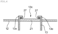
- the front part structure of the vehicle 1 illustrated in FIG. 4 includes the seal member 27 that provides blockage across the entire circumference between the periphery of the raised wall 21 and the inner peripheral surface of the communication space 13a, in the present embodiment, an opening edge of the front opening 13c in a state in which the raised wall 21 is closed.
- a highly airtight elastic material made of resin, rubber, or the like is used as the seal member 27 and preferably, for example, an EPDM rubber foamed body called EPTSEALER (registered trademark).
- the raised wall 21 illustrated in FIG. 4 may be arranged inside the communication space 13a instead of the front opening 13c of the communication space 13a and able to open and close the whole area of the opening section of the communication space 13a at a halfway position in the longitudinal direction.
- the seal member 27 may be arranged to provide blockage between the periphery of the raised wall 21 and the inner peripheral surface of the communication space 13a in a state in which the raised wall 21 is closed.
- the seal member 27 provides blockage between the periphery of the raised wall 21 and the opening edge of the front opening 13c in a state in which the whole area of an opening section (in the present embodiment, the front opening 13c) of a communication space 3a of the communication portion 13 is closed by the raised wall 21, smell of a package housed in the front trunk 12 or the part of the communication portion 13 on the front side in the vehicle 1 can be prevented from reaching inside the vehicle cabin 1b through the communication space 13a.
- noise generated by movement of a package housed in the front trunk 12 or the part of the communication portion 13 on the vehicle front side during traveling of the vehicle 1 can be prevented from being transferred into the vehicle cabin 1b through the communication space 13a.
- seal member 27 only needs to be provided at any one of the periphery of the raised wall 21 and the inner peripheral surface of the communication space 13a.
- the raised wall 21 can open and close the whole area of the opening section of the communication space 13a in the closed state, and the raised wall 21 may partition the communication space 13a in an airtight manner into parts on the front side and the rear side, respectively, in the vehicle front-rear direction (for example, partitions in an airtight manner by using the above-described seal member 27) in a state in which the raised wall 21 is closed.
- the raised wall 21 partitions the communication space 13a in an airtight manner into parts on the front side and the rear side, respectively, in the front-rear direction of the vehicle 1 in a state in which the whole area of the opening section of the communication portion 13 is closed by the raised wall 21, smell of a package housed in the front trunk 12 or the part of the communication portion 13 on the front side in the vehicle 1 can be prevented from reaching inside the vehicle cabin 1b through the communication space 13a.
- noise generated by movement of a package housed in the front trunk 12 or the part of the communication portion 13 on the front side in the vehicle 1 during traveling of the vehicle 1 can be prevented from being transferred into the vehicle cabin 1b through the communication space 13a.
- the pulling operation lever 28 may be provided as the opening-closing operation portion in place of the pressing operation lever 24 of the above-described second embodiment.
- the opening-closing operation portion includes the pulling operation lever 28 as an operation member that extends in the longitudinal direction of the communication portion 13 and opens and closes the raised wall 21 by moving in the longitudinal direction.
- the pulling operation lever 28 only needs to extend in the longitudinal direction of the communication portion 13 and be provided inside or outside the communication space 13a of the communication portion 13.
- the pulling operation lever 28 is supported to be freely movable back and forth in a longitudinal direction of the pulling operation lever 28 by a lever support portion 29 provided on the ceiling surface of the communication space 13a inside the communication space 13a.
- the pulling operation lever 28 includes an operation end part 28a provided inside or around the glove box 11, and a coupling end part 28b coupled to the raised wall 21.
- the coupling end part 28b is rotatably supported to the upper part of the raised wall 21.
- the upper end part of the raised wall 21 in FIG. 5 is rotatably supported to the rotational shaft portion 25 extending in the vehicle width direction (direction orthogonal to the sheet of FIG. 5 ).
- the operation end part 28a is housed, for example, inside the glove box 11.
- an occupant can easily perform an operation of opening the raised wall 21 toward the vehicle rear side by performing an operation of holding the operation end part 28a of the pulling operation lever 28 and pulling the pulling operation lever 28 in the vehicle cabin 1b.
- the raised wall 21 can be closed by own weight when the operation of pulling the pulling operation lever 28 is stopped. Thus, it is possible to easily perform an operation to open and close the raised wall 21 with the pulling operation lever 28.
- the raised wall 21 has a configuration that opens toward the vehicle rear side, and thus as for arrangement of the seal member 27 at the lower end part of the raised wall 21, the seal member 27 may be arranged at either the lower end part of the raised wall 21 or a bottom surface of the communication space 13a.
- both side edges of a surface of the raised wall 21 on the vehicle front side contact a pair of L-shaped frame parts 13e on respective sides in the vehicle width direction at the front opening 13c of the communication portion 13.
- the seal member 27 may be arranged at either the side edges of the surface of the raised wall 21 on the vehicle front side or the pair of L-shaped frame parts 13e.
- an operation member such as a wire or a cable
- an electric operation mechanism such as a solenoid
- the lid 11b of the first embodiment and the operation members such as the pressing operation lever 24 of the second embodiment and the pulling operation lever 28 of the third embodiment described above, are included in the opening-closing operation portion of the present invention.
- a connection counterpart of the communication portion 13 on the vehicle cabin 1b side is the glove box 11, but the connection counterpart of the communication portion on the vehicle cabin side in the present invention is not limited thereto.
- a housing portion different from a glove box may be provided at an upper or lower part of the instrument panel, and the housing portion may be the connection counterpart of the communication portion.
- the housing portion needs to be provided with an openable and closable lid in terms of prevention of smell leakage, package slippage, and the like.
- the vehicle cabin side housing portion is arranged at the front passenger seat side part 1d of the vehicle cabin 1b, but the present invention is not limited thereto.
- the vehicle cabin side housing portion may be provided at a front side part of a steering wheel at the instrument panel, or the vehicle cabin side housing portion may be provided on the front side between a driver seat and a front passenger seat.
- one front trunk 12 is provided at the front part 1a of the vehicle 1, but in the present invention, a plurality of front trunks may be provided at the front part of the vehicle. In this case, at least one of the front trunks only needs to be connected to the vehicle cabin side housing portion through the communication portion.
Landscapes
- Engineering & Computer Science (AREA)
- Mechanical Engineering (AREA)
- Chemical & Material Sciences (AREA)
- Combustion & Propulsion (AREA)
- Transportation (AREA)
- Vehicle Step Arrangements And Article Storage (AREA)
Abstract
[Problem] To provide a vehicle front part structure that can prevent unintentional package movement during vehicle traveling while allowing access to a trunk from a vehicle cabin side.
[Means for Solution] A vehicle includes a front trunk 12, a glove box 11, and a communication portion 13. The front trunk 12 has a housing space 12a that is disposed at a front part of the vehicle and can house a package. The glove box 11 is disposed at a front part of a vehicle cabin and, has a housing space 11a into and out of which a package can be taken, and is provided with a lid 11b that can open and close an opening. The communication portion 13 has a communication space 13a providing communication between the housing space 12a of the front trunk 12 and the housing space 11a of the glove box 11. In addition, a raised wall 21 as a movement restriction portion that restricts package movement in the communication space 13a is provided at an opening section of the communication space 13a of the communication portion 13, specifically, a front opening 13c at a front end part of the communication space 13a.
Description
- The present invention relates to a vehicle front part structure.
- Patent Literature 1 discloses a vehicle provided with a trunk at a front part. The trunk disclosed in
- Patent Literature 1 is formed of a resin material and arranged below a bonnet at the vehicle front part. A user can open the bonnet and take an object into and out of the trunk.
- [Patent Literature 1]
German Patent Application Publication No. 102020106560 - However, the trunk disclosed in Patent Literature 1 described above is inconvenient because stopping the vehicle and opening the bonnet is necessary every time accessing the trunk.
- Thus, it is thought to provide a communication portion through which the trunk provided at the vehicle front part communicates with a vehicle cabin.
- However, with the simple structure in which the trunk provided at the vehicle front part and the vehicle cabin communicate with each other through the communication portion, a package housed in a front trunk during vehicle traveling potentially moves into the vehicle cabin through the communication portion.
- The present invention has been made in view of the problem as described above and aims to provide a vehicle front part structure that can prevent unintentional package movement during vehicle traveling while allowing access to a trunk from a vehicle cabin side.
- A vehicle front part structure according to an aspect of the present invention is characterized by including a front trunk disposed at a vehicle front part on a front side of a vehicle cabin of a vehicle and having a front housing space that can house a package; a vehicle cabin side housing portion disposed at a front part of the vehicle cabin, having a vehicle cabin side housing space into and out of which a package can be taken from the vehicle cabin side, and provided with a lid that can open and close an opening of the vehicle cabin side housing space on the vehicle cabin side; a communication portion having a communication space providing communication between the front housing space and the vehicle cabin side housing space; and a movement restriction portion that is provided at the communication portion and restricts package movement in the communication space.
- In the vehicle front part structure according to the above-described aspect, since the front trunk at the vehicle front part, the vehicle cabin side housing portion at the vehicle cabin front part, and the communication portion having the communication space providing communication between the front housing space and the vehicle cabin side housing space are provided, it is possible to ensure a housing space in which a package can be accessed from both inside and outside the vehicle cabin while enlarging housing capacity of a trunk of the vehicle.
- Moreover, since the movement restriction portion that restricts package movement in the communication space is provided at the communication portion, packages housed in the front trunk or the communication portion can be prevented from unintentionally moving in a front-rear direction during vehicle traveling.
- In the vehicle front part structure according to the above-described aspect, the movement restriction portion may further include a projection, protruding inside the communication space from an inner surface of the communication portion, in at least one state of the projection.
- In the vehicle front part structure according to the above-described aspect, the movement restriction portion may further comprise a raised wall that can be displaced between a closed position where movement of the package is restricted by partitioning of at least part of an opening section of the front housing space in the communication space and an opened position where the movement restriction is canceled.
- In the vehicle front part structure according to the above-described aspect, it is possible to prevent package movement in the communication space as the raised wall at the closed position restricts package movement by partitioning at least part of an opening section of the communication space in the communication portion during vehicle traveling, and it is possible to smoothly perform package movement in the communication space as the raised wall is displaced from the closed position to the opened position to cancel the movement restriction when a package is taken into and out of the front trunk.
- In the vehicle front part structure according to the above-described aspect the raised wall may be arranged in a front opening of the communication space, which communicates with the housing space of the front trunk.
- In the vehicle front part structure according to the above-described aspect a lower or upper end part of the raised wall may be rotatably supported to a rotational shaft portion extending in the vehicle width direction. Accordingly, the raised wall can open and close at least part of the front opening of the communication space by swinging in the vehicle front-rear direction with the rotational shaft portion as a rotational axis.
- In the vehicle front part structure according to the above-described aspect the raised wall may close a whole area of the opening section of the communication space in a closed state.
- In the vehicle front part structure according to the above-described aspect the raised wall can close the whole area of the front opening but only needs to be able to close at least part, for example, lower half from a bottom surface of the front opening to restrict package movement, and in this case, the upper side of the raised wall may be opened.
- The vehicle front part structure according to the above-described aspect may further include an opening-closing operation portion that is operated to open and close the raised wall.
- In the vehicle front part structure according to the above-described aspect, with the opening-closing operation portion, an occupant of the vehicle can optionally open and close the raised wall by performing an operation to open and close the raised wall by using the opening-closing operation portion when desiring to open and close the raised wall.
- In the vehicle front part structure according to the above-described aspect, the opening-closing operation portion may comprise the lid of the vehicle cabin side housing portion, and the raised wall may be opened and closed in coordination with opening-closing operation of the lid.
- In the vehicle front part structure according to the above-described aspect, since the opening-closing operation portion includes the lid of the vehicle cabin side housing portion, an operation member for performing an operation to open and close the raised wall does not need to be provided in the vehicle cabin in addition to the lid, and the configuration of the vehicle cabin front part can be simplified. Moreover, since the raised wall is opened and closed in coordination with opening-closing operation of the lid, an operation to open and close the raised wall can be easily performed.
- Further, when the lid of the vehicle cabin side housing portion is opened to take a package in and out, the raised wall can be opened in coordination with opening operation of the lid and an occupant can move the package to an optional place in the front trunk or the communication portion while visually recognizing the package.
- In the vehicle front part structure according to an alternative embodiment, a link bar that extends in a longitudinal direction of the communication portion might be provided, wherein a rear end part of the link bar is coupled to the lid of the vehicle cabin side housing portion and a front end part of the link bar is coupled to an upper part of the raised wall.
- In the vehicle front part structure according to an alternative embodiment the raised wall may be opened and closed in coordination with the opening-closing operation of the lid such that when the lid is open the raised wall is open and if the lid is closed the raised wall is closed.
- In the vehicle front part structure according to an alternative embodiment the raised wall may be opened and closed in coordination with the inverse opening-closing operation of the lid such that when any one of the lid and the raised wall is open the other one is closed and vice-versa.
- In the vehicle front part structure according to the above-described aspect, the opening-closing operation portion may comprise an operation member that extends in a longitudinal direction of the communication portion and opens and closes the raised wall by moving in the longitudinal direction, and the operation member may include a coupling end part coupled to the raised wall, and an operation end part provided inside or around the vehicle cabin side housing portion.
- With the vehicle front part structure according to the above-described aspect, an occupant can easily perform an operation to open and close the raised wall only by holding the operation end part of the operation member in the vehicle cabin and operating the operation member. Moreover, it is possible to open and close the raised wall at an optional timing while maintaining a state in which the lid of the vehicle cabin side housing portion is opened, and thus an occupant in the vehicle cabin can reliably check an opened-closed state of the raised wall.
- In the vehicle front part structure according to the above-described aspect, the opening-closing operation portion is either a pulling operation lever or a pressing operation lever.
- Specifically, the pressing operation lever and the pressing operation lever are an operation member that extend in the longitudinal direction of the communication portion and open and close the raised wall by moving in the longitudinal direction.
- With the vehicle front part structure according to the above-described aspect, the raised wall can be closed by own weight when the operation of pressing the pressing operation lever is stopped or when the operation of pulling the pulling operation lever is stopped.
- In the vehicle front part structure according to the above-described aspect, a lever support portion may be provided on a ceiling surface of the communication space inside the communication space so that the operation lever is freely movable back and forth in a longitudinal direction of the vehicle.
- In the vehicle front part structure according to the above-described aspect, the raised wall can open and close the whole area of the opening section of the communication space in a closed state, and the vehicle front part structure may further include a seal member that provides sealing between a periphery of the raised wall and an inner peripheral surface of the communication space in a state in which the raised wall is closed.
- In the vehicle front part structure according to the above-described aspect, since the seal member provides blockage between the periphery of the raised wall and the inner peripheral surface of the communication space in a state in which the whole area of the opening section of the communication portion is closed by the raised wall, smell of a package housed in the front trunk or a part of the communication portion on the vehicle front side can be prevented from reaching inside the vehicle cabin through the communication space. In addition, noise generated by unintentional movement of a package housed in the front trunk or a part of the communication portion on the vehicle front side during vehicle traveling can be prevented from being transferred into the vehicle cabin through the communication space.
- In the vehicle front part structure according to the above-described aspect, the raised wall can open and close the whole area of the opening section of the communication space in a closed state, and the raised wall may partition the communication space in an airtight manner into parts on a front side and a rear side in a vehicle front-rear direction in a state in which the raised wall is closed.
- In the vehicle front part structure according to the above-described aspect, since the raised wall partitions the communication space in an airtight manner into parts on the front side and the rear side, respectively, in the vehicle front-rear direction in a state in which the whole area of the opening section of the communication portion is closed by the raised wall, smell of a package housed in the front trunk or a part of the communication portion on the vehicle front side can be prevented from reaching inside the vehicle cabin through the communication space. In addition, noise generated by unintentional movement of a package housed in the front trunk or a part of the communication portion on the vehicle front side during vehicle traveling can be prevented from being transferred into the vehicle cabin through the communication space.
- In the vehicle front part structure according to the above-described aspect, the vehicle cabin side housing portion may be a glove box provided at an instrument panel.
- In the vehicle front part structure according to the above-described aspect, the glove box may have a front opening on the front side and a rear opening on the rear side, wherein preferably a lower end part of the lid is rotatably supported to a rotational shaft portion extending in a vehicle width direction such that the rear opening can be opened and closed by the lid.
- In the vehicle front part structure according to the above-described aspect, since the glove box provided at the instrument panel is used as the vehicle cabin side housing portion, space inside the vehicle cabin can be effectively utilized. Moreover, without change of arrangement in the vehicle cabin, the front trunk can be accessed from the glove box through the communication portion to move a package.
- With a vehicle front part structure according to each of the above-described aspects, it is possible to prevent unintentional package movement during vehicle traveling while allowing access to a trunk from a vehicle cabin side.
-
-
FIG. 1 is a schematic diagram illustrating a vehicle front part structure according to a first embodiment. -
FIG. 2 is a cross-sectional view illustrating a line II-II section inFIG. 1 and is a cross-sectional view illustrating a state in which a lid of a glove box and a raised wall are closed. -
FIG. 3 is a cross-sectional view illustrating a state in which the lid of the glove box and the raised wall inFIG. 2 are opened. -
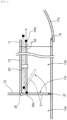
FIG. 4 is a cross-sectional view of a structure including a press lever with which the raised wall as part of a vehicle front part structure according to a second embodiment is opened while being pressed. -
FIG. 5 is a cross-sectional view of a structure including a pulling operation lever with which the raised wall as part of a vehicle front part structure according to a third embodiment is opened while being pulled. -
FIG. 6 is a cross-sectional view of the raised wall and its peripheral part inFIG. 5 when cut in a horizontal direction. - Embodiments of the present invention will be described below with reference to drawings. Note that the embodiments described below are examples of the present invention, and the present invention is not limited to the embodiments described below except for its essential configuration. Note that, in
FIGS. 1 to 3 , "FR" indicates a vehicle front side, "RR" indicates a vehicle rear side, "RH" indicates a vehicle right side, "LH" indicates a vehicle left side, "UP" indicates a vehicle upper side, and "LO" indicates a vehicle lower side. - An overview of a front part structure of a vehicle 1 according to a first embodiment will be described below with reference to
FIG. 1 . - As illustrated in
FIG. 1 , the vehicle 1 according to the present embodiment includes afront trunk 12 at afront part 1a on the front side of adash panel 1c. Thefront trunk 12 is disposed below a bonnet (not illustrated) and has a space that can house a package. - The vehicle 1 includes an
instrument panel 10 in avehicle cabin 1b on the rear side of thedash panel 1c. Theinstrument panel 10 is disposed at a front side part of thevehicle cabin 1b and extends in the right-left direction. Theinstrument panel 10 is provided with aglove box 11 at a part on the front side of a front passengerseat side part 1d. - The
glove box 11 has a configuration with which a package can be taken in and out from thevehicle cabin 1b side. Theglove box 11 of the present embodiment corresponds to a vehicle cabin side housing portion. - The vehicle 1 further includes a
communication portion 13 connecting thefront trunk 12 and theglove box 11. In other words, in the vehicle 1 according to the present embodiment, ahousing space 12a of thefront trunk 12 and ahousing space 11a of theglove box 11 communicate with each other through thecommunication portion 13. - The vehicle 1 also includes a raised
wall 21 that opens and closes an opening section of acommunication space 13a of thecommunication portion 13, specifically, afront opening 13c that is opened on the vehicle front side in thecommunication space 13a, and alink bar 22 that links the raisedwall 21 to opening and closing of alid 11b of theglove box 11. The raisedwall 21 of the present embodiment corresponds to a movement restriction portion that restricts movement between thefront trunk 12 and thecommunication portion 13. - The configuration of connection of the
front trunk 12 and theglove box 11 to thecommunication portion 13 will be described below with reference toFIG. 2 . - As illustrated in
FIG. 2 , thefront trunk 12 has anopening 12b on the upper side and has arear opening 12e on the lower side of arear wall 12d. A package can be taken into and out of thehousing space 12a of thefront trunk 12 through theopening 12b. - Note that, in the present embodiment, an
inner bottom surface 12c of thefront trunk 12 has a configuration as a substantially horizontal plane. Since theinner bottom surface 12c has a configuration as a horizontal plane, a package placed on theinner bottom surface 12c is unlikely to move to front, rear, right, and left. - The
glove box 11 has afront opening 11d on the front side and has arear opening 11e on the rear side. Therear opening 11e can be opened and closed by thelid 11b. - A lower end part of the
lid 11b is rotatably supported to arotational shaft portion 11f extending in a vehicle width direction (direction orthogonal to the sheet ofFIG. 2 ). Accordingly, thelid 11b can open and close therear opening 11e by swinging in a vehicle front-rear direction with therotational shaft portion 11f as a rotational axis as illustrated inFIGS. 2 and3 . - The
housing space 11a of theglove box 11 is formed between thefront opening 11d and therear opening 11e in the front-rear direction of the vehicle 1. Aninner bottom surface 11c of theglove box 11 has a configuration as a substantially horizontal plane. - The
communication portion 13 has thecommunication space 13a extending in the front-rear direction and has a tubular configuration that its circumference is covered by a wall portion. Thecommunication space 13a of thecommunication portion 13 is connected to therear opening 12e of thehousing space 12a of thefront trunk 12 at thefront opening 13c on the front side and connected to thefront opening 11d of thehousing space 11a of theglove box 11 at arear opening 13d on the rear side. Aninner bottom surface 13b of thecommunication portion 13 has a configuration as a substantially horizontal plane and has a configuration connected to each of theinner bottom surface 12c of thefront trunk 12 and theinner bottom surface 11c of theglove box 11 without a step. - As illustrated in
FIGS. 2 and3 , the raisedwall 21 serves as the movement restriction portion that is provided at thefront opening 13c of thecommunication portion 13 to extend in the vehicle width direction (direction orthogonal to the sheets ofFIGS. 2 and3 ) and restricts package movement in thecommunication space 13a. - The raised
wall 21 is arranged in thecommunication space 13a. Specifically, the raisedwall 21 of the present embodiment is arranged in thefront opening 13c of thecommunication space 13a, which communicates with thehousing space 12a of thefront trunk 12. A lower end part of the raisedwall 21 is rotatably supported to arotational shaft portion 23 extending in the vehicle width direction (direction orthogonal to the sheet ofFIG. 2 ). Accordingly, the raisedwall 21 can open and close at least part of thefront opening 13c (in the present embodiment, the whole area of thefront opening 13c) of thecommunication space 13a by swinging in the vehicle front-rear direction with therotational shaft portion 23 as a rotational axis. In the present embodiment, the raisedwall 21 can close the whole area of thefront opening 13c but only needs to be able to close at least part, for example, lower half from a bottom surface of thefront opening 13c to restrict package movement, and in this case, the upper side of the raisedwall 21 may be opened. - In the present embodiment, since the raised
wall 21 can open and close the whole area of thefront opening 13c of thecommunication space 13a, a seal member 27 (refer toFIGS. 4 to 6 ) to be described later may be provided at either the periphery of the raisedwall 21 or the periphery of thefront opening 13c of thecommunication space 13a. In this case, in a state in which the raisedwall 21 is closed, smell of a package housed in thefront trunk 12 can be prevented from reaching theglove box 11 on the vehicle cabin side through thecommunication space 13a. In addition, noise generated by unintentional package movement in thefront trunk 12 during vehicle traveling can be prevented from reaching theglove box 11 on the vehicle cabin side through thecommunication space 13a. - The vehicle front part structure of the present embodiment includes an opening-closing operation portion that is operated to open and close the raised
wall 21. The opening-closing operation portion is constituted by thelid 11b of theglove box 11 and thelink bar 22 that links and connects thelid 11b and the raisedwall 21. - The
link bar 22 extends in a longitudinal direction of thecommunication portion 13 inside or outside thecommunication space 13a of thecommunication portion 13. Arear end part 22a of thelink bar 22 is rotatably coupled to an upper part of thelid 11b of theglove box 11. Afront end part 22b of thelink bar 22 is rotatably coupled to an upper part of the raisedwall 21. Accordingly, the raisedwall 21 is linked and connected to thelid 11b through thelink bar 22 and thus can open and close in coordination with opening-closing operation of thelid 11b. Specifically, when an occupant of the vehicle 1 opens thelid 11b of theglove box 11, the upper part of the raisedwall 21 is pulled toward the vehicle rear side by thelink bar 22 so that the raisedwall 21 can open while inclining to the vehicle rear side. When thelid 11b is closed, the upper part of the raisedwall 21 is pressed toward the vehicle front side by thelink bar 22 so that the raisedwall 21 can close while standing up toward the vehicle front side. - At least one
link bar 22 needs to be arranged inside or outside thecommunication space 13a, and two or more link bars may be arranged depending on the shape and size of thecommunication space 13a. - The front part structure of the vehicle 1 of the present embodiment includes the
front trunk 12 at thefront part 1a of the vehicle 1, theglove box 11 at the front part of thevehicle cabin 1b, and thecommunication portion 13 having thecommunication space 13a providing communication between thehousing space 12a of thefront trunk 12 and thehousing space 11a of theglove box 11. Accordingly, it is possible to ensure a housing space in which a package can be accessed from both inside and outside thevehicle cabin 1b while enlarging housing capacity of a trunk of the vehicle 1. - Moreover, since the raised
wall 21 as the movement restriction portion that restricts package movement in thecommunication space 13a is provided at thecommunication portion 13, packages housed in thefront trunk 12 or thecommunication portion 13 can be prevented from unintentionally moving in the front-rear direction during vehicle traveling. - Note that the movement restriction portion in the present invention may be not only the above-described raised
wall 21 but also any member that can restrict a package in thecommunication space 13a, and the movement restriction portion of the present invention also includes a projection or bar-shaped body protruding inside thecommunication space 13a from the inner peripheral surface of thecommunication portion 13. - The movement restriction portion of the present embodiment is the raised
wall 21 that is arranged in thecommunication space 13a (in the present embodiment, thefront opening 13c of thecommunication space 13a) communicating with thehousing space 12a of thefront trunk 12 in thecommunication space 13a and can be displaced between a closed position where package movement is restricted by partitioning of at least part of the opening section of thecommunication space 13a and an opened position where the movement restriction is canceled (note that the opening section is a transverse cross section at an optional position in the entire longitudinal direction of thecommunication space 13a, and thefront opening 13c and therear opening 13d are included in the opening section). Thus, during vehicle traveling, the raisedwall 21 closes at least part of the opening section of thecommunication space 13a (in the present embodiment, the whole area of thefront opening 13c) in thecommunication portion 13, thereby preventing unintended package movement in thecommunication space 13a. When a package is taken into and out of thefront trunk 12, the raisedwall 21 is opened to cancel the movement prevention so that package movement in thecommunication space 13a can be smoothly performed. - Note that the raised
wall 21 only needs to partition at least part of the opening section of thecommunication space 13a, and thus may be arranged at an optional position other than thefront opening 13c at a front end part of thecommunication space 13a, for example, an optional position between thefront opening 13c and therear opening 13d in the longitudinal direction of thecommunication space 13a. Moreover, the raisedwall 21 only needs to be able to restrict package movement by partitioning at least part of the opening section of thecommunication space 13a, and thus may have, for example, a configuration that closes 1/10 to 1/2 approximately of the opening section in the height direction from a lowest position at the opening section of thecommunication space 13a (for example, thefront opening 13c). - The front part structure of the vehicle 1 of the present embodiment further includes combination of the
lid 11b of theglove box 11 and thelink bar 22 as the opening-closing operation portion that is operated to open and close the raisedwall 21. Thus, with combination of thelid 11b and thelink bar 22 as the opening-closing operation portion, when desiring to open and close the raisedwall 21, an occupant of the vehicle 1 can optionally open and close the raisedwall 21 by performing an operation to open and close the raisedwall 21 by using the opening-closing operation portion (in other words, thelid 11b and the link bar 22). - In addition, in the present embodiment, since the opening-closing operation portion includes the
lid 11b of theglove box 11, an operation member for performing an operation to open and close the raised wall does not need to be provided in thevehicle cabin 1b in addition to thelid 11b, and thus the configuration of the front part of thevehicle cabin 1b can be simplified. Moreover, since the raisedwall 21 opens and closes in coordination with opening-closing operation of thelid 11b, an operation to open and close the raisedwall 21 can be easily performed. - Further, it is possible to open the raised
wall 21 in coordination with opening operation of thelid 11b when opening thelid 11b of theglove box 11 and taking in and out a package, and an occupant can move the package to an optional place in thefront trunk 12 or thecommunication portion 13 while visually recognizing the package. - Note that, in the present embodiment, the raised
wall 21 only needs to open and close in coordination with opening-closing operation of thelid 11b, and thus not only an aspect that the raisedwall 21 is opened in coordination with opening operation of thelid 11b as described above but also an aspect that the raisedwall 21 is closed in coordination with opening operation of thelid 11b are applicable. In this case, the raisedwall 21 may be opened in coordination with closing operation of thelid 11b. In such an aspect, since any one of thelid 11b and the raisedwall 21 is opened and the other is closed, it is possible to prevent a state in which thehousing space 12a of thefront trunk 12 and thevehicle cabin 1b communicate with each other, and it is possible to prevent smell in thehousing space 12a from flowing into thevehicle cabin 1b. - Further, in the above-described embodiment, the
glove box 11 provided at theinstrument panel 10 is used as an example of the vehicle cabin side housing portion of the present invention. Space in thevehicle cabin 1b can be effectively utilized by using the glove box provided at theinstrument panel 10 as the vehicle cabin side housing portion. Moreover, thefront trunk 12 can be accessed from theglove box 11 through thecommunication portion 13 to move a package without change of arrangement in thevehicle cabin 1b. - Furthermore, in the front part structure of the vehicle 1 illustrated in
FIGS. 1 to 3 , the raisedwall 21 can open and close the whole area of the opening section of thecommunication space 13a in a closed state, and the raisedwall 21 may partition thecommunication space 13a in an airtight manner into parts on the front side and the rear side, respectively, in the vehicle front-rear direction (for example, partitions in an airtight manner by using theseal member 27 to be described later) in a state in which the raisedwall 21 is closed. - With this configuration, in a state in which the whole area of the opening section of the
communication portion 13 is closed by the raisedwall 21, the raisedwall 21 partitions thecommunication space 13a in an airtight manner parts on the front side and the rear side, respectively, in the front-rear direction of the vehicle 1, and thus smell of a package housed in thefront trunk 12 or the part on the front side of the vehicle 1 in thecommunication portion 13 can be prevented from reaching inside thevehicle cabin 1b through thecommunication space 13a. In addition, noise generated by movement of a package housed in thefront trunk 12 or the part of thecommunication portion 13 on the front side in the vehicle 1 during traveling of the vehicle 1 can be prevented from being transferred into thevehicle cabin 1b through thecommunication space 13a. - Note that, the opening-closing operation portion in the present invention is not limited to the above-described configuration including the
lid 11b but may be provided with an operation member (apressing operation lever 24 inFIG. 4 or a pullingoperation lever 28 inFIG. 5 ) separately from thelid 11b as in second to third embodiments below. - As illustrated in
FIG. 4 , a front part structure of the vehicle 1 of the second embodiment is the same as the front part structure of the first embodiment in that theglove box 11, thefront trunk 12, and thecommunication portion 13 illustrated inFIGS. 1 to 3 are provided, but is largely different therefrom in that thepressing operation lever 24 is provided as the opening-closing operation portion separately from thelid 11b. - Specifically, in the front part structure of the vehicle 1 of the second embodiment, the opening-closing operation portion includes the
pressing operation lever 24 as an operation member that extends in the longitudinal direction of thecommunication portion 13 and opens and closes the raisedwall 21 by moving in the longitudinal direction. Thepressing operation lever 24 only needs to extend in the longitudinal direction of thecommunication portion 13 and be provided inside or outside thecommunication space 13a of thecommunication portion 13. In the present embodiment, thepressing operation lever 24 is supported to be freely movable back and forth in a longitudinal direction of thepressing operation lever 24 by alever support portion 26 provided on a ceiling surface of thecommunication space 13a inside thecommunication space 13a. - The
pressing operation lever 24 includes anoperation end part 24a provided inside or around theglove box 11, and acoupling end part 24b coupled to the raisedwall 21. Thecoupling end part 24b is rotatably supported to the upper part of the raisedwall 21. An upper end part of the raisedwall 21 inFIG. 4 is rotatably supported to arotational shaft portion 25 extending in the vehicle width direction (direction orthogonal to the sheet ofFIG. 4 ). Theoperation end part 24a is housed, for example, inside theglove box 11. Alternatively, theoperation end part 24a may be provided at a position around theglove box 11 where an occupant in the vehicle cabin can hold and operate theoperation end part 24a. - With the front part structure of the vehicle 1 including the
pressing operation lever 24 illustrated inFIG. 4 , an occupant can easily perform an operation of opening the raisedwall 21 toward the vehicle front side by performing an operation of holding theoperation end part 24a of thepressing operation lever 24 and pressing thepressing operation lever 24 in thevehicle cabin 1b. The raisedwall 21 can be closed by own weight when the operation of pressing thepressing operation lever 24 is stopped. Thus, it is possible to easily perform an operation to open and close the raisedwall 21 with thepressing operation lever 24. - Moreover, it is possible to open and close the raised
wall 21 at an optional timing while maintaining a state in which thelid 11b of theglove box 11 is opened, and thus an occupant in thevehicle cabin 1b can reliably check an opened-closed state of the raisedwall 21. - Further, in the front part structure of the vehicle 1 illustrated in
FIG. 4 , the raisedwall 21 can open and close the whole area of thefront opening 13c of thecommunication space 13a in the closed state. - In addition, the front part structure of the vehicle 1 illustrated in
FIG. 4 includes theseal member 27 that provides blockage across the entire circumference between the periphery of the raisedwall 21 and the inner peripheral surface of thecommunication space 13a, in the present embodiment, an opening edge of thefront opening 13c in a state in which the raisedwall 21 is closed. A highly airtight elastic material made of resin, rubber, or the like is used as theseal member 27 and preferably, for example, an EPDM rubber foamed body called EPTSEALER (registered trademark). - Note that, in the closed state, the raised
wall 21 illustrated inFIG. 4 may be arranged inside thecommunication space 13a instead of thefront opening 13c of thecommunication space 13a and able to open and close the whole area of the opening section of thecommunication space 13a at a halfway position in the longitudinal direction. In this case, theseal member 27 may be arranged to provide blockage between the periphery of the raisedwall 21 and the inner peripheral surface of thecommunication space 13a in a state in which the raisedwall 21 is closed. - In the front part structure of the vehicle 1 illustrated in
FIG. 4 , since theseal member 27 provides blockage between the periphery of the raisedwall 21 and the opening edge of thefront opening 13c in a state in which the whole area of an opening section (in the present embodiment, thefront opening 13c) of a communication space 3a of thecommunication portion 13 is closed by the raisedwall 21, smell of a package housed in thefront trunk 12 or the part of thecommunication portion 13 on the front side in the vehicle 1 can be prevented from reaching inside thevehicle cabin 1b through thecommunication space 13a. In addition, noise generated by movement of a package housed in thefront trunk 12 or the part of thecommunication portion 13 on the vehicle front side during traveling of the vehicle 1 can be prevented from being transferred into thevehicle cabin 1b through thecommunication space 13a. - Note that the
seal member 27 only needs to be provided at any one of the periphery of the raisedwall 21 and the inner peripheral surface of thecommunication space 13a. - In the front part structure of the vehicle 1 illustrated in
FIG. 4 , as well, the raisedwall 21 can open and close the whole area of the opening section of thecommunication space 13a in the closed state, and the raisedwall 21 may partition thecommunication space 13a in an airtight manner into parts on the front side and the rear side, respectively, in the vehicle front-rear direction (for example, partitions in an airtight manner by using the above-described seal member 27) in a state in which the raisedwall 21 is closed. - With this configuration, since the raised
wall 21 partitions thecommunication space 13a in an airtight manner into parts on the front side and the rear side, respectively, in the front-rear direction of the vehicle 1 in a state in which the whole area of the opening section of thecommunication portion 13 is closed by the raisedwall 21, smell of a package housed in thefront trunk 12 or the part of thecommunication portion 13 on the front side in the vehicle 1 can be prevented from reaching inside thevehicle cabin 1b through thecommunication space 13a. In addition, noise generated by movement of a package housed in thefront trunk 12 or the part of thecommunication portion 13 on the front side in the vehicle 1 during traveling of the vehicle 1 can be prevented from being transferred into thevehicle cabin 1b through thecommunication space 13a. - As illustrated in
FIG. 5 , the pullingoperation lever 28 may be provided as the opening-closing operation portion in place of thepressing operation lever 24 of the above-described second embodiment. - Specifically, in a front part structure of the vehicle 1 of the third embodiment, the opening-closing operation portion includes the pulling
operation lever 28 as an operation member that extends in the longitudinal direction of thecommunication portion 13 and opens and closes the raisedwall 21 by moving in the longitudinal direction. The pullingoperation lever 28 only needs to extend in the longitudinal direction of thecommunication portion 13 and be provided inside or outside thecommunication space 13a of thecommunication portion 13. In the present embodiment, the pullingoperation lever 28 is supported to be freely movable back and forth in a longitudinal direction of the pullingoperation lever 28 by alever support portion 29 provided on the ceiling surface of thecommunication space 13a inside thecommunication space 13a. - The pulling
operation lever 28 includes anoperation end part 28a provided inside or around theglove box 11, and acoupling end part 28b coupled to the raisedwall 21. Thecoupling end part 28b is rotatably supported to the upper part of the raisedwall 21. The upper end part of the raisedwall 21 inFIG. 5 is rotatably supported to therotational shaft portion 25 extending in the vehicle width direction (direction orthogonal to the sheet ofFIG. 5 ). Theoperation end part 28a is housed, for example, inside theglove box 11. - With the front part structure of the vehicle 1 including the pulling
operation lever 28 illustrated inFIG. 5 , an occupant can easily perform an operation of opening the raisedwall 21 toward the vehicle rear side by performing an operation of holding theoperation end part 28a of the pullingoperation lever 28 and pulling the pullingoperation lever 28 in thevehicle cabin 1b. The raisedwall 21 can be closed by own weight when the operation of pulling the pullingoperation lever 28 is stopped. Thus, it is possible to easily perform an operation to open and close the raisedwall 21 with the pullingoperation lever 28. - Moreover, it is possible to open and close the raised
wall 21 at an optional timing while maintaining a state in which thelid 11b of theglove box 11 is opened, and thus an occupant in thevehicle cabin 1b can reliably check the opened-closed state of the raisedwall 21. - In the front part structure of the vehicle 1 illustrated in
FIG. 5 , the raisedwall 21 has a configuration that opens toward the vehicle rear side, and thus as for arrangement of theseal member 27 at the lower end part of the raisedwall 21, theseal member 27 may be arranged at either the lower end part of the raisedwall 21 or a bottom surface of thecommunication space 13a. - In a horizontal cross-sectional view of the raised
wall 21 in the closed state illustrated inFIG. 6 , both side edges of a surface of the raisedwall 21 on the vehicle front side contact a pair of L-shapedframe parts 13e on respective sides in the vehicle width direction at thefront opening 13c of thecommunication portion 13. Thus, theseal member 27 may be arranged at either the side edges of the surface of the raisedwall 21 on the vehicle front side or the pair of L-shapedframe parts 13e. - As other aspects of the opening-closing operation portion that is operated to open and close the raised wall in the present invention, for example, an operation member such as a wire or a cable, and an electric operation mechanism such as a solenoid, other than the
lid 11b of the first embodiment and the operation members such as thepressing operation lever 24 of the second embodiment and the pullingoperation lever 28 of the third embodiment described above, are included in the opening-closing operation portion of the present invention. - In each of the above-described first to third embodiments, a connection counterpart of the
communication portion 13 on thevehicle cabin 1b side is theglove box 11, but the connection counterpart of the communication portion on the vehicle cabin side in the present invention is not limited thereto. A housing portion different from a glove box may be provided at an upper or lower part of the instrument panel, and the housing portion may be the connection counterpart of the communication portion. However, in this case, the housing portion needs to be provided with an openable and closable lid in terms of prevention of smell leakage, package slippage, and the like. - Moreover, in each of the above-described first to third embodiments, since the connection counterpart of the
communication portion 13 on thevehicle cabin 1b side is theglove box 11, the vehicle cabin side housing portion is arranged at the front passengerseat side part 1d of thevehicle cabin 1b, but the present invention is not limited thereto. For example, the vehicle cabin side housing portion may be provided at a front side part of a steering wheel at the instrument panel, or the vehicle cabin side housing portion may be provided on the front side between a driver seat and a front passenger seat. - Further, in each of the above-described first to third embodiments, one
front trunk 12 is provided at thefront part 1a of the vehicle 1, but in the present invention, a plurality of front trunks may be provided at the front part of the vehicle. In this case, at least one of the front trunks only needs to be connected to the vehicle cabin side housing portion through the communication portion. -
- 1
- vehicle
- 1a
- front part
- 10
- instrument panel
- 11
- glove box (vehicle cabin side housing part)
- 12
- front trunk
- 12a
- front housing space
- 13
- communication portion
- 13a
- communication space
- 21
- raised wall (movement restriction portion)
- 24
- pressing operation lever (operation member)
- 24a
- operation end part
- 24b
- coupling end part
- 27
- seal member
- 28
- pulling operation lever (operation member)
- 28a
- operation end part
- 28b
- coupling end part
Claims (15)
- A vehicle front part structure characterized by comprising:a front trunk (12) disposed at a vehicle (1) front part (1a) on a front side of a vehicle cabin (1b) of a vehicle (1) and having a front housing space (12a) that can house a package;a vehicle cabin side housing portion (11) disposed at a front part of the vehicle cabin (1b), having a vehicle cabin side housing space (11a) into and out of which a package can be taken from the vehicle cabin (1b) side, and provided with a lid (11b) that can open and close an opening of the vehicle cabin side housing space (11) on the vehicle cabin (1b) side;a communication portion (13) having a communication space (13a) providing communication between the front housing space (12a) and the vehicle cabin side housing space (11a); anda movement restriction portion (21) that is provided at the communication portion (13) and restricts package movement in the communication space (13a).
- The vehicle front part structure according to claim 1, wherein the movement restriction portion (21) includes a projection, protruding inside the communication space (13a) from an inner surface of the communication portion (13), in at least one state of the projection.
- The vehicle front part structure according to any one of the preceding claims, wherein the movement restriction portion (21) comprises a raised wall (21) that is arranged in the communication space (13a) and can be displaced between a closed position where movement of the package is restricted by partitioning of at least part of an opening section of the communication space (13a) and an opened position where the movement restriction is canceled.
- The vehicle front part structure according to claim 3, wherein the raised wall (21) is arranged in a front opening (13c) of the communication space (13a), which communicates with the housing space (12a) of the front trunk (12).
- The vehicle front part structure according to claim 3 or 4, wherein a lower or upper end part of the raised wall (21) is rotatably supported to a rotational shaft portion (23) extending in the vehicle width direction.
- The vehicle front part structure according to one of claims 3 to 5, wherein the raised wall (21) closes a whole area of the opening section of the communication space (13a) in a closed state.
- The vehicle front part structure according to claims 3 to 6, further comprising an opening-closing operation portion that is operated to open and close the raised wall (21).
- The vehicle front part structure according to claim 7, wherein the opening-closing operation portion comprises the lid (11b) of the vehicle cabin side housing portion (11), andthe raised wall (21) is opened and closed in coordination with an opening-closing operation of the lid,wherein preferably, a link bar (22) that extends in a longitudinal direction of the communication portion (13) is provided , wherein a rear end part (22a) of the link bar (22) is coupled to the lid (11b) of the vehicle cabin side housing portion (11) and a front end part (22b) of the link bar (22) is coupled to an upper part of the raised wall (21),and/or wherein preferably, the raised wall (21) is opened and closed in coordination with the opening-closing operation of the lid (11b) such that when the lid (11b) is open the raised wall (21) is open and if the lid is closed the raised wall (21) is closed or, alternatively, the raised wall (21) is opened and closed in coordination with the inverse opening-closing operation of the lid (11b) such that when any one of the lid (11b) and the raised wall (21) is open the other one is closed and vice-versa.
- The vehicle front part structure according to claim 6, whereinthe opening-closing operation portion comprises an operation member (24, 28) that extends in a longitudinal direction of the communication portion (13) and opens and closes the raised wall (21) by moving in the longitudinal direction, andthe operation member (24, 28) includes a coupling end part (24b, 28b) coupled to the raised wall (21), and an operation end part (24a, 28a) provided inside or around the vehicle cabin side housing portion (11).
- The vehicle front part structure according to claims 8 or 9, wherein the opening-closing operation portion is either a pulling operation lever (28) or a pressing operation lever (24).
- The vehicle front part structure according to claims 8 to 10, wherein a lever support portion (26) is provided on a ceiling surface of the communication space (13a) inside the communication space (13a) so that the operation lever (24) is freely movable back and forth in a longitudinal direction of the vehicle (1).
- The vehicle front part structure according to claims 2 to 11, whereinthe raised wall can open and close a whole area of the opening section of the communication space in a closed state, andthe vehicle (1) front part (1a) structure further includes a seal member (27) that provides sealing between a periphery of the raised wall (21) and an inner peripheral surface of the communication space (13a) in a state in which the raised wall (21) is closed.
- The vehicle front part structure according to claim 2 to 12, whereinthe raised wall can open and close a whole area of the opening section of the communication space in a closed state, andthe raised wall partitions the communication space in an airtight manner into parts on a front side and a rear side in a vehicle front-rear direction in a state in which the raised wall is closed.
- The vehicle front part structure according to any one of the preceding claims, wherein the vehicle cabin side housing portion (11) is a glove box (11) provided at an instrument panel, wherein preferably the glove box (11) has a front opening (11d) on the front side and a rear opening (11e) on the rear side, wherein preferably a lower end part of the lid (11b) is rotatably supported to a rotational shaft portion (11f) extending in a vehicle (1) width direction such that the rear opening (11e) can be opened and closed by the lid (11b).
- A vehicle (1) comprising a vehicle front part structure (1a) according to any one of the preceding claims.
Applications Claiming Priority (1)
| Application Number | Priority Date | Filing Date | Title |
|---|---|---|---|
| JP2023102300A JP2025002250A (en) | 2023-06-22 | 2023-06-22 | Vehicle front structure |
Publications (1)
| Publication Number | Publication Date |
|---|---|
| EP4480755A1 true EP4480755A1 (en) | 2024-12-25 |
Family
ID=91375666
Family Applications (1)
| Application Number | Title | Priority Date | Filing Date |
|---|---|---|---|
| EP24179455.1A Pending EP4480755A1 (en) | 2023-06-22 | 2024-06-03 | Vehicle front part structure |
Country Status (4)
| Country | Link |
|---|---|
| US (1) | US20240424995A1 (en) |
| EP (1) | EP4480755A1 (en) |
| JP (1) | JP2025002250A (en) |
| CN (1) | CN119176191A (en) |
Citations (4)
| Publication number | Priority date | Publication date | Assignee | Title |
|---|---|---|---|---|
| US10676137B2 (en) * | 2018-05-21 | 2020-06-09 | Bollinger Motors, LLC | Automotive vehicle body |
| DE102020106560A1 (en) | 2020-03-11 | 2021-09-16 | Audi Aktiengesellschaft | Vehicle with a front trunk |
| US20220289113A1 (en) * | 2021-03-09 | 2022-09-15 | Ford Global Technologies, Llc | Vehicle having sliding drawer positionable between compartments |
| DE102022109830A1 (en) * | 2022-04-25 | 2023-03-16 | Audi Aktiengesellschaft | Through-loading device for enlarging a loading space in the vehicle front area |
-
2023
- 2023-06-22 JP JP2023102300A patent/JP2025002250A/en active Pending
-
2024
- 2024-03-21 CN CN202410325323.1A patent/CN119176191A/en active Pending
- 2024-06-03 EP EP24179455.1A patent/EP4480755A1/en active Pending
- 2024-06-10 US US18/738,854 patent/US20240424995A1/en active Pending
Patent Citations (4)
| Publication number | Priority date | Publication date | Assignee | Title |
|---|---|---|---|---|
| US10676137B2 (en) * | 2018-05-21 | 2020-06-09 | Bollinger Motors, LLC | Automotive vehicle body |
| DE102020106560A1 (en) | 2020-03-11 | 2021-09-16 | Audi Aktiengesellschaft | Vehicle with a front trunk |
| US20220289113A1 (en) * | 2021-03-09 | 2022-09-15 | Ford Global Technologies, Llc | Vehicle having sliding drawer positionable between compartments |
| DE102022109830A1 (en) * | 2022-04-25 | 2023-03-16 | Audi Aktiengesellschaft | Through-loading device for enlarging a loading space in the vehicle front area |
Also Published As
| Publication number | Publication date |
|---|---|
| CN119176191A (en) | 2024-12-24 |
| US20240424995A1 (en) | 2024-12-26 |
| JP2025002250A (en) | 2025-01-09 |
Similar Documents
| Publication | Publication Date | Title |
|---|---|---|
| EP0546668B1 (en) | Glove compartment | |
| US6513863B1 (en) | Vehicle interior door apparatus and interlock system | |
| US8152221B2 (en) | Vehicle slide door structure | |
| US9016759B2 (en) | Vehicle including net structure | |
| US7845712B2 (en) | Vehicle closure assembly with sealed split between independently selectable closure panels | |
| US20110057467A1 (en) | Parcel shelf structure | |
| EP1078795A2 (en) | Opening/closing rear component structure of a vehicle | |
| US6874839B2 (en) | Vehicle endgate with integral door | |
| CN101981266B (en) | Door device for small-sized vehicle | |
| JP5760645B2 (en) | Rear cargo compartment structure of vehicle | |
| US20240424995A1 (en) | Vehicle front part structure | |
| EP3012137B1 (en) | Tailgate-equipped vehicle body structure | |
| EP2998141B1 (en) | Vehicle | |
| JP4193482B2 (en) | Rear cargo compartment structure of vehicle | |
| JPH04212654A (en) | Safety belt device for the back seat of a car | |
| US12151543B2 (en) | Release system for removable vehicle panel | |
| JP2002046472A (en) | Two-way slide system vehicle back door device | |
| JP6986223B2 (en) | Vehicle door opening structure | |
| JP2015020490A (en) | Instrument panel of automobile | |
| JPH0446034Y2 (en) | ||
| JPH0948245A (en) | Rear door for vehicle | |
| JPS6317143A (en) | Rear trunk room structure of automobile | |
| JP2002104031A (en) | Vehicle child seat fixing structure | |
| CN105539100A (en) | vehicle door | |
| JP6104219B2 (en) | vehicle |
Legal Events
| Date | Code | Title | Description |
|---|---|---|---|
| PUAI | Public reference made under article 153(3) epc to a published international application that has entered the european phase |
Free format text: ORIGINAL CODE: 0009012 |
|
| STAA | Information on the status of an ep patent application or granted ep patent |
Free format text: STATUS: THE APPLICATION HAS BEEN PUBLISHED |
|
| AK | Designated contracting states |
Kind code of ref document: A1 Designated state(s): AL AT BE BG CH CY CZ DE DK EE ES FI FR GB GR HR HU IE IS IT LI LT LU LV MC ME MK MT NL NO PL PT RO RS SE SI SK SM TR |
|
| STAA | Information on the status of an ep patent application or granted ep patent |
Free format text: STATUS: REQUEST FOR EXAMINATION WAS MADE |
|
| 17P | Request for examination filed |
Effective date: 20250620 |