EP4480726A2 - Variable speed for transport engineless refrigeration unit - Google Patents
Variable speed for transport engineless refrigeration unit Download PDFInfo
- Publication number
- EP4480726A2 EP4480726A2 EP24204373.5A EP24204373A EP4480726A2 EP 4480726 A2 EP4480726 A2 EP 4480726A2 EP 24204373 A EP24204373 A EP 24204373A EP 4480726 A2 EP4480726 A2 EP 4480726A2
- Authority
- EP
- European Patent Office
- Prior art keywords
- drive unit
- transportation refrigeration
- electrical power
- unit
- frequency
- Prior art date
- Legal status (The legal status is an assumption and is not a legal conclusion. Google has not performed a legal analysis and makes no representation as to the accuracy of the status listed.)
- Granted
Links
Images


Classifications
-
- B—PERFORMING OPERATIONS; TRANSPORTING
- B60—VEHICLES IN GENERAL
- B60H—ARRANGEMENTS OF HEATING, COOLING, VENTILATING OR OTHER AIR-TREATING DEVICES SPECIALLY ADAPTED FOR PASSENGER OR GOODS SPACES OF VEHICLES
- B60H1/00—Heating, cooling or ventilating devices
- B60H1/00421—Driving arrangements for parts of a vehicle air-conditioning
- B60H1/00428—Driving arrangements for parts of a vehicle air-conditioning electric
-
- B—PERFORMING OPERATIONS; TRANSPORTING
- B60—VEHICLES IN GENERAL
- B60H—ARRANGEMENTS OF HEATING, COOLING, VENTILATING OR OTHER AIR-TREATING DEVICES SPECIALLY ADAPTED FOR PASSENGER OR GOODS SPACES OF VEHICLES
- B60H1/00—Heating, cooling or ventilating devices
- B60H1/32—Cooling devices
- B60H1/3204—Cooling devices using compression
- B60H1/3232—Cooling devices using compression particularly adapted for load transporting vehicles
-
- B—PERFORMING OPERATIONS; TRANSPORTING
- B60—VEHICLES IN GENERAL
- B60H—ARRANGEMENTS OF HEATING, COOLING, VENTILATING OR OTHER AIR-TREATING DEVICES SPECIALLY ADAPTED FOR PASSENGER OR GOODS SPACES OF VEHICLES
- B60H1/00—Heating, cooling or ventilating devices
- B60H1/32—Cooling devices
- B60H2001/3236—Cooling devices information from a variable is obtained
- B60H2001/3255—Cooling devices information from a variable is obtained related to temperature
- B60H2001/3261—Cooling devices information from a variable is obtained related to temperature of the air at an evaporating unit
-
- B—PERFORMING OPERATIONS; TRANSPORTING
- B60—VEHICLES IN GENERAL
- B60H—ARRANGEMENTS OF HEATING, COOLING, VENTILATING OR OTHER AIR-TREATING DEVICES SPECIALLY ADAPTED FOR PASSENGER OR GOODS SPACES OF VEHICLES
- B60H1/00—Heating, cooling or ventilating devices
- B60H1/32—Cooling devices
- B60H2001/3269—Cooling devices output of a control signal
- B60H2001/327—Cooling devices output of a control signal related to a compressing unit
- B60H2001/3272—Cooling devices output of a control signal related to a compressing unit to control the revolving speed of a compressor
-
- B—PERFORMING OPERATIONS; TRANSPORTING
- B60—VEHICLES IN GENERAL
- B60H—ARRANGEMENTS OF HEATING, COOLING, VENTILATING OR OTHER AIR-TREATING DEVICES SPECIALLY ADAPTED FOR PASSENGER OR GOODS SPACES OF VEHICLES
- B60H1/00—Heating, cooling or ventilating devices
- B60H1/32—Cooling devices
- B60H2001/3286—Constructional features
- B60H2001/3292—Compressor drive is electric only
-
- Y—GENERAL TAGGING OF NEW TECHNOLOGICAL DEVELOPMENTS; GENERAL TAGGING OF CROSS-SECTIONAL TECHNOLOGIES SPANNING OVER SEVERAL SECTIONS OF THE IPC; TECHNICAL SUBJECTS COVERED BY FORMER USPC CROSS-REFERENCE ART COLLECTIONS [XRACs] AND DIGESTS
- Y02—TECHNOLOGIES OR APPLICATIONS FOR MITIGATION OR ADAPTATION AGAINST CLIMATE CHANGE
- Y02T—CLIMATE CHANGE MITIGATION TECHNOLOGIES RELATED TO TRANSPORTATION
- Y02T10/00—Road transport of goods or passengers
- Y02T10/80—Technologies aiming to reduce greenhouse gasses emissions common to all road transportation technologies
- Y02T10/88—Optimized components or subsystems, e.g. lighting, actively controlled glasses
Definitions
- the subject matter disclosed herein generally relates to transportation refrigeration units, and more specifically transportation refrigeration units powered by an engine of a vehicle, such as a truck, into which the transportation refrigeration unit is installed.
- Refrigeration systems typically include a compressor, a condenser, an expansion valve, and an evaporator serially connected by refrigerant lines in a closed refrigerant circuit in accord with known refrigerant vapor compression cycles.
- a power unit such as a combustion engine, drives the compressor of the refrigeration unit, and may be diesel powered, natural gas powered, or other type of engine.
- the compressor is driven by the engine shaft either through a belt drive or by a mechanical shaft-to-shaft link.
- the an Eco-Drive ® generator is connected to the vehicle engine to convert rotational energy of the vehicle engine into electrical power and distributes the electrical power to components of the transportation refrigeration unit for the use thereof.
- Eco-Drive ® When Eco-Drive ® is installed on truck and commissioned for operation, the system is set to provide a continuous and nominal power at 400V/3/50Hz or 460V/3/62 Hz to the transportation refrigeration unit.
- components of the transport refrigeration unit such as a compressor and an evaporator fan, have only one fixed speed of operation.
- a transportation refrigeration unit for cooling a cargo compartment includes a compressor configured to compress a refrigerant, a compressor motor configured to drive the compressor, an evaporator heat exchanger operatively coupled to the compressor and an evaporator fan configured to provide return airflow from a return air intake and flow the return airflow over the evaporator heat exchanger.
- a drive unit is configured to deliver variable frequency electrical power between a minimum frequency and a maximum frequency to the compressor motor and the evaporator fan. A frequency of the electrical power is based on one or more sensed parameters of the transportation refrigeration unit.
- the drive unit is configured to deliver electrical power in the range of 35 Hz to 65 Hz.
- the drive unit is an electrical generator operably connected to a vehicle engine.
- the electrical generator is operably connected to the vehicle engine via a hydraulic pump, the electrical generator converting hydraulic power to electrical power.
- the one or more sensed parameters includes one or more of a difference between a cargo compartment temperature and a set point temperature or a door position of the cargo compartment.
- the electrical power is continuously variable between the minimum frequency and the maximum frequency.
- control unit is operably connected to the drive unit to command the drive unit based on the one or more sensed parameters.
- a transportation refrigeration system in another embodiment, includes a vehicle including a vehicle engine to drive the vehicle, a cargo compartment, and a transportation refrigeration unit configured to cool the cargo compartment.
- the transportation refrigeration unit includes a compressor configured to compress a refrigerant, a compressor motor configured to drive the compressor, an evaporator heat exchanger operatively coupled to the compressor, and an evaporator fan configured to provide return airflow from a return air intake and flow the return airflow over the evaporator heat exchanger.
- a drive unit is operably connected to, and driven by the vehicle engine. The drive unit is configured to deliver variable frequency electrical power between a minimum frequency and a maximum frequency to the compressor motor and the evaporator fan. A frequency of the electrical power is based on one or more sensed parameters of the transportation refrigeration unit.
- the drive unit is configured to deliver electrical power in the range of 35 Hz to 65 Hz.
- the drive unit is an electrical generator operably connected to the vehicle engine.
- the electrical generator is operably connected to the vehicle engine via a hydraulic pump, the electrical generator converting hydraulic power to electrical power.
- the one or more sensed parameters includes one or more of a difference between a cargo compartment temperature and a set point temperature or a door position of the cargo compartment.
- the electrical power is continuously variable between the minimum frequency and the maximum frequency.
- control unit is operably connected to the drive unit to command the drive unit based on the one or more sensed parameters.
- a method of operating a transportation refrigeration unit includes powering a drive unit of the transportation unit using a vehicle engine, operating one or more of a compressor motor and an evaporator fan of the transportation refrigeration unit via electrical power provided by the drive unit, and varying a frequency of the electrical power provided by the drive unit between a minimum frequency and a maximum frequency.
- the frequency is varied based on one or more sensed operating parameters of the transportation refrigeration unit.
- the one or more sensed parameters includes a difference between a cargo compartment temperature and a set point temperature.
- the one or more sensed parameters includes a door position of the cargo compartment.
- the drive unit is configured to deliver electrical power in the range of 35 Hz to 65 Hz.
- the electrical power is continuously variable between the minimum frequency and the maximum frequency.
- the transport refrigeration system 20 includes a vehicle, for example, a truck 22, having a cargo compartment 24.
- An engineless transportation refrigeration unit (TRU) 26 is utilized to provide a desired temperature and humidity range.
- a vehicle engine 28 such as a gasoline or diesel combustion engine, provides power to drive movement of the truck 22, and a drive unit 30 is utilized to provide electrical power to the TRU 26.
- the drive unit 30 is connected to the vehicle engine 28 such that the drive unit 30 converts rotational energy from the vehicle engine 28 into electrical power, which the drive unit 30 distributes to various components of the transportation refrigeration unit 26 to power the components.
- the vehicle may be a truck, train, boat, airplane, helicopter, etc.
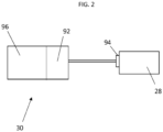
- the drive unit 30 is a hydraulic system including a hydraulic pump 92 connected to and driven by the vehicle engine 28 at a power take off 94.
- An electrical generator 96 is connected to the hydraulic pump 92 and converts the hydraulic power to electrical power.
- the cargo compartment 24 may include a top wall 32, a bottom wall 34 opposed to and spaced from the top wall 32, two side walls 36 spaced from and opposed to one-another, and opposing front and rear walls 38, 40.
- the cargo compartment 24 may further include doors (not shown) at the rear wall 40, or any other wall.
- transport refrigeration systems 20 are used to transport and distribute cargo, such as, for example perishable goods and environmentally sensitive goods (herein referred to as perishable goods).
- the perishable goods may include but are not limited to fruits, vegetables, grains, beans, nuts, eggs, dairy, seed, flowers, meat, poultry, fish, ice, blood, pharmaceuticals, or any other suitable cargo requiring cold chain transport.
- the TRU 26 is associated with a cargo compartment 24 to provide desired environmental parameters, such as, for example temperature, pressure, humidity, carbon dioxide, ethylene, ozone, light exposure, vibration exposure, and other conditions to the cargo compartment 24.
- the TRU 26 is a refrigeration system capable of providing a desired temperature and humidity range.
- the engineless TRU 26 is generally integrated into the cargo compartment 24 and may be mounted to the front wall 38.
- the cargo is maintained at a desired temperature by cooling of the cargo compartment 24 via the TRU 26 that circulates airflow into and through the cargo compartment 24.
- the components of the engineless TRU 26 may include a compressor 42, an electric compressor motor 44, a condenser 46 that may be air cooled, a condenser fan assembly 48, a receiver 50, a filter dryer 52, a heat exchanger 54, a thermostatic expansion valve 56, an evaporator 58, an evaporator fan assembly 60, a suction modulation valve 62, and a control unit 64 that may include a computer-based processor (e.g., microprocessor).
- a computer-based processor e.g., microprocessor
- Operation of the engineless TRU 26 may best be understood by starting at the compressor 42, where the suction gas, for example, a refrigerant gas, enters the compressor at a suction port 66 and is compressed to a higher temperature and pressure.
- the refrigerant gas is emitted from the compressor at an outlet port 68 and may then flow into tube(s) 70 of the condenser 46.
- the air flow across the condenser 46 may be facilitated by one or more fans 72 of the condenser fan assembly 48.
- the condenser fans 72 may be driven by respective condenser fan motors 74 of the condenser fan assembly 70 that may be electric.
- the gas within the tubes 70 condenses to a high pressure and high temperature liquid and flows to the receiver 50 that provides storage for excess liquid refrigerant during low temperature operation.
- the liquid refrigerant may pass through a sub-cooler heat exchanger 76 of the condenser 46, through the filter-dryer 52 that keeps the refrigerant clean and dry, then to the heat exchanger 54 that increases the refrigerant sub-cooling, and finally to the thermostatic expansion valve 56.
- liquid refrigerant passes through the orifices of the expansion valve 56, some of the liquid vaporizes into a gas (i.e., flash gas).
- a gas i.e., flash gas
- Return air from the refrigerated space i.e., cargo compartment 24
- the refrigerant flows through a plurality of tubes 78 of the evaporator 58, the remaining liquid refrigerant absorbs heat from the return air, and in so doing, is vaporized.
- the evaporator fan assembly 60 includes one or more evaporator fans 80 that may be driven by respective fan motors 82 that may be electric. The air flow across the evaporator 58 is facilitated by the evaporator fans 80. From the evaporator 58, the refrigerant, in vapor form, may then flow through the suction modulation valve 62, and back to the compressor 42.
- a thermostatic expansion valve bulb sensor 84 may be located proximate to an outlet of the evaporator tube 78. The bulb sensor 84 is intended to control the thermostatic expansion valve 56, thereby controlling refrigerant superheat at an outlet of the evaporator tube 78.
- HFCs such as R-404a, R-134a, R452a, R448a, R453a, R454a and natural refrigerants such as propane and ammonia.
- natural refrigerants such as propane and ammonia.
- Other refrigerant systems may also be applied that use carbon dioxide (CO 2 ) refrigerant, and that may be a two-stage vapor compression system.
- CO 2 carbon dioxide
- a bypass valve may facilitate the flash gas of the refrigerant to bypass the evaporator 58. This will allow the evaporator coil to be filled with liquid and completely 'wetted' to improve heat transfer efficiency. With CO 2 refrigerant, this bypass flash gas may be re-introduced into a mid-stage of a two-stage compressor.
- the compressor 42 and the compressor motor 44 may be linked via an interconnecting drive shaft 86.
- the compressor 42, the compressor motor 44 and the drive shaft 86 may all be sealed within a common housing 88.
- the compressor 42 may be a single compressor.
- the single compressor may be a two-stage compressor, a scroll-type compressor or other compressors adapted to compress HFCs or natural refrigerants.
- the natural refrigerant may be CO 2 , propane, ammonia, or any other natural refrigerant that may include a global-warming potential (GWP) of about one (1).
- GWP global-warming potential
- the drive unit 30 is connected to electrically-driven components of the TRU 26, such as the compressor motor 44, evaporator fan assembly 60 and condenser fan assembly 48, and the control unit 64, via a plurality of electrical pathways 90.
- the control unit 64 is configured to command a frequency of operation of the drive unit 30, such that sufficient electrical power is delivered to the TRU 26 components based on operational parameters of the transport refrigeration system 20.
- the operational frequency of the drive unit 30 is variable, and in some embodiments is continuously variable in a frequency range between a minimum frequency and a maximum frequency. In some embodiments, the minimum frequency is 35 Hz and the maximum frequency is 65 Hz.
- Operating the drive unit 30 at the minimum frequency provides a minimum cooling capacity from the compressor 42 and a minimum airflow from the evaporator fan assembly 60 and condenser fan assembly 48.
- operating the drive unit 30 at the maximum frequency provides a maximum cooling capacity from the compressor 42 and a maximum airflow from the evaporator fan assembly 60 and condenser fan assembly 48.
- the drive unit 30 is operable at any frequencies between the minimum frequency and the maximum frequency to tune cooling capacity provided by the compressor 42 and airflow provided by the evaporator fan assembly 60 and the condenser fan assembly 48.
- the control unit 64 utilizes parameters such as set point temperature of the TRU 26, actual temperature in the cargo compartment 24, delta temperature between the actual temperature and the set point temperature, whether or not cargo compartment doors are opened or closed, etc., to determine an optimal drive unit 30 frequency within the frequency range to produce a desired level of electrical power to meet the electrical power needs of the TRU 26. For example, in operating conditions where the delta temperature (cargo compartment temperature minus set point temperature) is relatively high, the control unit 64 will command the drive unit 30 to operate at maximum power at the maximum frequency until the set point temperature is reached and equaled by the cargo compartment temperature. Conversely, in operating conditions where the delta temperature is relatively low, the control unit 64 will command the drive unit top operate at maximum power at the minimum frequency until the set point temperature is reached.
- parameters such as set point temperature of the TRU 26, actual temperature in the cargo compartment 24, delta temperature between the actual temperature and the set point temperature, whether or not cargo compartment doors are opened or closed, etc.
- Utilizing a drive unit 30 having variable frequency of operation has the technical effect of reducing set point recovery times especially in cases where the delta temperature is relatively high. Further, such capability improves efficiency of the TRU 26 and fuel efficiency of the vehicle engine 28, and also reduces CO 2 emissions of the vehicle engine 28. Further, controlling operating frequency at the drive unit 30 alleviates the need to incorporate complex variable speed components in the fan assemblies and the compressor, and is beneficially efficient and reliable compared to such components.
Landscapes
- Physics & Mathematics (AREA)
- Thermal Sciences (AREA)
- Engineering & Computer Science (AREA)
- Mechanical Engineering (AREA)
- Devices That Are Associated With Refrigeration Equipment (AREA)
Abstract
Description
- The subject matter disclosed herein generally relates to transportation refrigeration units, and more specifically transportation refrigeration units powered by an engine of a vehicle, such as a truck, into which the transportation refrigeration unit is installed.
- Traditional refrigerated cargo trucks or refrigerated tractor trailers, such as those utilized to transport cargo via sea, rail, or road, is a truck, trailer or cargo container, generally defining a cargo compartment, and modified to include a refrigeration system located at one end of the truck, trailer, or cargo container. Refrigeration systems typically include a compressor, a condenser, an expansion valve, and an evaporator serially connected by refrigerant lines in a closed refrigerant circuit in accord with known refrigerant vapor compression cycles. A power unit, such as a combustion engine, drives the compressor of the refrigeration unit, and may be diesel powered, natural gas powered, or other type of engine. In many tractor trailer transport refrigeration systems, the compressor is driven by the engine shaft either through a belt drive or by a mechanical shaft-to-shaft link.
- In some systems, the an Eco-Drive® generator is connected to the vehicle engine to convert rotational energy of the vehicle engine into electrical power and distributes the electrical power to components of the transportation refrigeration unit for the use thereof. When Eco-Drive® is installed on truck and commissioned for operation, the system is set to provide a continuous and nominal power at 400V/3/50Hz or 460V/3/62 Hz to the transportation refrigeration unit. As a consequence components of the transport refrigeration unit, such as a compressor and an evaporator fan, have only one fixed speed of operation.
- In one embodiment, a transportation refrigeration unit for cooling a cargo compartment includes a compressor configured to compress a refrigerant, a compressor motor configured to drive the compressor, an evaporator heat exchanger operatively coupled to the compressor and an evaporator fan configured to provide return airflow from a return air intake and flow the return airflow over the evaporator heat exchanger. A drive unit is configured to deliver variable frequency electrical power between a minimum frequency and a maximum frequency to the compressor motor and the evaporator fan. A frequency of the electrical power is based on one or more sensed parameters of the transportation refrigeration unit.
- Additionally or alternatively, in this or other embodiments the drive unit is configured to deliver electrical power in the range of 35 Hz to 65 Hz.
- Additionally or alternatively, in this or other embodiments the drive unit is an electrical generator operably connected to a vehicle engine.
- Additionally or alternatively, in this or other embodiments the electrical generator is operably connected to the vehicle engine via a hydraulic pump, the electrical generator converting hydraulic power to electrical power.
- Additionally or alternatively, in this or other embodiments the one or more sensed parameters includes one or more of a difference between a cargo compartment temperature and a set point temperature or a door position of the cargo compartment.
- Additionally or alternatively, in this or other embodiments the electrical power is continuously variable between the minimum frequency and the maximum frequency.
- Additionally or alternatively, in this or other embodiments a control unit is operably connected to the drive unit to command the drive unit based on the one or more sensed parameters.
- In another embodiment, a transportation refrigeration system includes a vehicle including a vehicle engine to drive the vehicle, a cargo compartment, and a transportation refrigeration unit configured to cool the cargo compartment. The transportation refrigeration unit includes a compressor configured to compress a refrigerant, a compressor motor configured to drive the compressor, an evaporator heat exchanger operatively coupled to the compressor, and an evaporator fan configured to provide return airflow from a return air intake and flow the return airflow over the evaporator heat exchanger. A drive unit is operably connected to, and driven by the vehicle engine. The drive unit is configured to deliver variable frequency electrical power between a minimum frequency and a maximum frequency to the compressor motor and the evaporator fan. A frequency of the electrical power is based on one or more sensed parameters of the transportation refrigeration unit.
- Additionally or alternatively, in this or other embodiments the drive unit is configured to deliver electrical power in the range of 35 Hz to 65 Hz.
- Additionally or alternatively, in this or other embodiments the drive unit is an electrical generator operably connected to the vehicle engine.
- Additionally or alternatively, in this or other embodiments the electrical generator is operably connected to the vehicle engine via a hydraulic pump, the electrical generator converting hydraulic power to electrical power.
- Additionally or alternatively, in this or other embodiments the one or more sensed parameters includes one or more of a difference between a cargo compartment temperature and a set point temperature or a door position of the cargo compartment.
- Additionally or alternatively, in this or other embodiments the electrical power is continuously variable between the minimum frequency and the maximum frequency.
- Additionally or alternatively, in this or other embodiments a control unit is operably connected to the drive unit to command the drive unit based on the one or more sensed parameters.
- In yet another embodiment, a method of operating a transportation refrigeration unit includes powering a drive unit of the transportation unit using a vehicle engine, operating one or more of a compressor motor and an evaporator fan of the transportation refrigeration unit via electrical power provided by the drive unit, and varying a frequency of the electrical power provided by the drive unit between a minimum frequency and a maximum frequency.
- Additionally or alternatively, in this or other embodiments the frequency is varied based on one or more sensed operating parameters of the transportation refrigeration unit.
- Additionally or alternatively, in this or other embodiments the one or more sensed parameters includes a difference between a cargo compartment temperature and a set point temperature.
- Additionally or alternatively, in this or other embodiments the one or more sensed parameters includes a door position of the cargo compartment.
- Additionally or alternatively, in this or other embodiments the drive unit is configured to deliver electrical power in the range of 35 Hz to 65 Hz.
- Additionally or alternatively, in this or other embodiments the electrical power is continuously variable between the minimum frequency and the maximum frequency.
- The following descriptions should not be considered limiting in any way. With reference to the accompanying drawings, like elements are numbered alike:
-
FIG. 1 is a schematic illustration of an embodiment of a vehicle having a refrigerated cargo container; -
FIG. 2 is a schematic view of a power drive unit for a refrigerated cargo container; -
FIG. 3 is a schematic illustration of an embodiment of a cargo container; and -
FIG. 4 is a schematic illustration of an embodiment of a transportation refrigeration unit. - A detailed description of one or more embodiments of the disclosed apparatus and method are presented herein by way of exemplification and not limitation with reference to the Figures.
- Referring to
FIG. 1 , atransport refrigeration system 20 of the present disclosure is illustrated. In the illustrated embodiment, thetransport refrigeration system 20 includes a vehicle, for example, atruck 22, having acargo compartment 24. An engineless transportation refrigeration unit (TRU) 26 is utilized to provide a desired temperature and humidity range. Avehicle engine 28, such as a gasoline or diesel combustion engine, provides power to drive movement of thetruck 22, and adrive unit 30 is utilized to provide electrical power to the TRU 26. Thedrive unit 30 is connected to thevehicle engine 28 such that thedrive unit 30 converts rotational energy from thevehicle engine 28 into electrical power, which thedrive unit 30 distributes to various components of thetransportation refrigeration unit 26 to power the components. It is understood that embodiments described herein may be applied to shipping containers that are shipped by rail, sea, air, or any other suitable container, thus the vehicle may be a truck, train, boat, airplane, helicopter, etc. - Referring to
FIG. 2 , in some embodiments thedrive unit 30 is a hydraulic system including ahydraulic pump 92 connected to and driven by thevehicle engine 28 at a power take off 94. Anelectrical generator 96 is connected to thehydraulic pump 92 and converts the hydraulic power to electrical power. - Referring to
FIG. 3 , thecargo compartment 24 may include atop wall 32, abottom wall 34 opposed to and spaced from thetop wall 32, twoside walls 36 spaced from and opposed to one-another, and opposing front andrear walls cargo compartment 24 may further include doors (not shown) at therear wall 40, or any other wall. - Typically,
transport refrigeration systems 20 are used to transport and distribute cargo, such as, for example perishable goods and environmentally sensitive goods (herein referred to as perishable goods). The perishable goods may include but are not limited to fruits, vegetables, grains, beans, nuts, eggs, dairy, seed, flowers, meat, poultry, fish, ice, blood, pharmaceuticals, or any other suitable cargo requiring cold chain transport. In the illustrated embodiment, the TRU 26 is associated with acargo compartment 24 to provide desired environmental parameters, such as, for example temperature, pressure, humidity, carbon dioxide, ethylene, ozone, light exposure, vibration exposure, and other conditions to thecargo compartment 24. In further embodiments, the TRU 26 is a refrigeration system capable of providing a desired temperature and humidity range. - The engineless TRU 26 is generally integrated into the
cargo compartment 24 and may be mounted to thefront wall 38. The cargo is maintained at a desired temperature by cooling of thecargo compartment 24 via the TRU 26 that circulates airflow into and through thecargo compartment 24. - Referring now to
FIG. 4 , the components of the engineless TRU 26 may include acompressor 42, anelectric compressor motor 44, acondenser 46 that may be air cooled, acondenser fan assembly 48, areceiver 50, afilter dryer 52, aheat exchanger 54, athermostatic expansion valve 56, anevaporator 58, anevaporator fan assembly 60, asuction modulation valve 62, and acontrol unit 64 that may include a computer-based processor (e.g., microprocessor). Operation of the engineless TRU 26 may best be understood by starting at thecompressor 42, where the suction gas, for example, a refrigerant gas, enters the compressor at asuction port 66 and is compressed to a higher temperature and pressure. The refrigerant gas is emitted from the compressor at anoutlet port 68 and may then flow into tube(s) 70 of thecondenser 46. - Air flowing across a plurality of condenser coil fins (not shown) and the
tubes 70, cools the gas to its saturation temperature. The air flow across thecondenser 46 may be facilitated by one ormore fans 72 of thecondenser fan assembly 48. Thecondenser fans 72 may be driven by respectivecondenser fan motors 74 of thecondenser fan assembly 70 that may be electric. - By removing latent heat, the gas within the
tubes 70 condenses to a high pressure and high temperature liquid and flows to thereceiver 50 that provides storage for excess liquid refrigerant during low temperature operation. From thereceiver 50, the liquid refrigerant may pass through asub-cooler heat exchanger 76 of thecondenser 46, through the filter-dryer 52 that keeps the refrigerant clean and dry, then to theheat exchanger 54 that increases the refrigerant sub-cooling, and finally to thethermostatic expansion valve 56. - As the liquid refrigerant passes through the orifices of the
expansion valve 56, some of the liquid vaporizes into a gas (i.e., flash gas). Return air from the refrigerated space (i.e., cargo compartment 24) flows over the heat transfer surface of theevaporator 58. As the refrigerant flows through a plurality oftubes 78 of theevaporator 58, the remaining liquid refrigerant absorbs heat from the return air, and in so doing, is vaporized. - The
evaporator fan assembly 60 includes one or moreevaporator fans 80 that may be driven byrespective fan motors 82 that may be electric. The air flow across theevaporator 58 is facilitated by theevaporator fans 80. From theevaporator 58, the refrigerant, in vapor form, may then flow through thesuction modulation valve 62, and back to thecompressor 42. A thermostatic expansionvalve bulb sensor 84 may be located proximate to an outlet of theevaporator tube 78. Thebulb sensor 84 is intended to control thethermostatic expansion valve 56, thereby controlling refrigerant superheat at an outlet of theevaporator tube 78. It is further contemplated and understood that the above generally describes a single stage vapor compression system that may be used for HFCs such as R-404a, R-134a, R452a, R448a, R453a, R454a and natural refrigerants such as propane and ammonia. Other refrigerant systems may also be applied that use carbon dioxide (CO2) refrigerant, and that may be a two-stage vapor compression system. It is to be appreciated, however, that the listed refrigerants are merely examples thereof, and other refrigerants may be utilized. - A bypass valve (not shown) may facilitate the flash gas of the refrigerant to bypass the
evaporator 58. This will allow the evaporator coil to be filled with liquid and completely 'wetted' to improve heat transfer efficiency. With CO2 refrigerant, this bypass flash gas may be re-introduced into a mid-stage of a two-stage compressor. - The
compressor 42 and thecompressor motor 44 may be linked via an interconnectingdrive shaft 86. Thecompressor 42, thecompressor motor 44 and thedrive shaft 86 may all be sealed within acommon housing 88. Thecompressor 42 may be a single compressor. The single compressor may be a two-stage compressor, a scroll-type compressor or other compressors adapted to compress HFCs or natural refrigerants. The natural refrigerant may be CO2, propane, ammonia, or any other natural refrigerant that may include a global-warming potential (GWP) of about one (1). - The
drive unit 30 is connected to electrically-driven components of theTRU 26, such as thecompressor motor 44,evaporator fan assembly 60 andcondenser fan assembly 48, and thecontrol unit 64, via a plurality ofelectrical pathways 90. Thecontrol unit 64 is configured to command a frequency of operation of thedrive unit 30, such that sufficient electrical power is delivered to theTRU 26 components based on operational parameters of thetransport refrigeration system 20. The operational frequency of thedrive unit 30 is variable, and in some embodiments is continuously variable in a frequency range between a minimum frequency and a maximum frequency. In some embodiments, the minimum frequency is 35 Hz and the maximum frequency is 65 Hz. Operating thedrive unit 30 at the minimum frequency provides a minimum cooling capacity from thecompressor 42 and a minimum airflow from theevaporator fan assembly 60 andcondenser fan assembly 48. Likewise, operating thedrive unit 30 at the maximum frequency provides a maximum cooling capacity from thecompressor 42 and a maximum airflow from theevaporator fan assembly 60 andcondenser fan assembly 48. In some embodiments, thedrive unit 30 is operable at any frequencies between the minimum frequency and the maximum frequency to tune cooling capacity provided by thecompressor 42 and airflow provided by theevaporator fan assembly 60 and thecondenser fan assembly 48. - The
control unit 64 utilizes parameters such as set point temperature of theTRU 26, actual temperature in thecargo compartment 24, delta temperature between the actual temperature and the set point temperature, whether or not cargo compartment doors are opened or closed, etc., to determine anoptimal drive unit 30 frequency within the frequency range to produce a desired level of electrical power to meet the electrical power needs of theTRU 26. For example, in operating conditions where the delta temperature (cargo compartment temperature minus set point temperature) is relatively high, thecontrol unit 64 will command thedrive unit 30 to operate at maximum power at the maximum frequency until the set point temperature is reached and equaled by the cargo compartment temperature. Conversely, in operating conditions where the delta temperature is relatively low, thecontrol unit 64 will command the drive unit top operate at maximum power at the minimum frequency until the set point temperature is reached. - Utilizing a
drive unit 30 having variable frequency of operation has the technical effect of reducing set point recovery times especially in cases where the delta temperature is relatively high. Further, such capability improves efficiency of theTRU 26 and fuel efficiency of thevehicle engine 28, and also reduces CO2 emissions of thevehicle engine 28. Further, controlling operating frequency at thedrive unit 30 alleviates the need to incorporate complex variable speed components in the fan assemblies and the compressor, and is beneficially efficient and reliable compared to such components. - The term "about" is intended to include the degree of error associated with measurement of the particular quantity based upon the equipment available at the time of filing the application.
- The terminology used herein is for the purpose of describing particular embodiments only and is not intended to be limiting of the present disclosure. As used herein, the singular forms "a", "an" and "the" are intended to include the plural forms as well, unless the context clearly indicates otherwise. It will be further understood that the terms "comprises" and/or "comprising," when used in this specification, specify the presence of stated features, integers, steps, operations, elements, and/or components, but do not preclude the presence or addition of one or more other features, integers, steps, operations, element components, and/or groups thereof.
- While the present disclosure has been described with reference to an exemplary embodiment or embodiments, it will be understood by those skilled in the art that various changes may be made and equivalents may be substituted for elements thereof without departing from the scope of the present disclosure. In addition, many modifications may be made to adapt a particular situation or material to the teachings of the present disclosure without departing from the essential scope thereof. Therefore, it is intended that the present disclosure not be limited to the particular embodiment disclosed as the best mode contemplated for carrying out this present disclosure, but that the present disclosure will include all embodiments falling within the scope of the claims.
- The following clauses recite features of the invention which may or may not presently be claimed, but which may serve as basis for amendments and/or one or more divisional applications:
- 1. A transportation refrigeration unit for cooling a cargo compartment comprising: a compressor configured to compress a refrigerant; a compressor motor configured to drive the compressor; an evaporator heat exchanger operatively coupled to the compressor; an evaporator fan configured to provide return airflow from a return air intake and flow the return airflow over the evaporator heat exchanger; a drive unit configured to deliver variable frequency electrical power between a minimum frequency and a maximum frequency to the compressor motor and the evaporator fan, a frequency of the electrical power based on one or more sensed parameters of the transportation refrigeration unit.
- 2. The transportation refrigeration unit of clause 1, wherein the drive unit is configured to deliver electrical power in the range of 35 Hz to 65 Hz.
- 3. The transportation refrigeration unit of clause 1 or 2, wherein the drive unit is an electrical generator operably connected to a vehicle engine.
- 4. The transportation refrigeration unit of clause 3, wherein the electrical generator is operably connected to the vehicle engine via a hydraulic pump, the electrical generator converting hydraulic power to electrical power.
- 5. The transportation refrigeration unit of any one of clauses 1 to 4, wherein the one or more sensed parameters includes one or more of a difference between a cargo compartment temperature and a set point temperature or a door position of the cargo compartment.
- 6. The transportation refrigeration unit of any one of clauses 1 to 5, wherein the electrical power is continuously variable between the minimum frequency and the maximum frequency.
- 7. The transportation refrigeration unit of any one of clauses 1 to 6, further comprising a control unit operably connected to the drive unit to command the drive unit based on the one or more sensed parameters.
- 8. A transportation refrigeration system, comprising: a vehicle including: a vehicle engine to drive the vehicle; and a cargo compartment; and a transportation refrigeration unit configured to cool the cargo compartment, including: a compressor configured to compress a refrigerant; a compressor motor configured to drive the compressor; an evaporator heat exchanger operatively coupled to the compressor; an evaporator fan configured to provide return airflow from a return air intake and flow the return airflow over the evaporator heat exchanger; a drive unit operably connected to, and driven by the vehicle engine, the drive unit configured to deliver variable frequency electrical power between a minimum frequency and a maximum frequency to the compressor motor and the evaporator fan, a frequency of the electrical power based on one or more sensed parameters of the transportation refrigeration unit.
- 9. The transportation refrigeration system of clause 8, wherein the drive unit is configured to deliver electrical power in the range of 35 Hz to 65 Hz.
- 10. The transportation refrigeration system of clause 8 or 9, wherein the drive unit is an electrical generator operably connected to the vehicle engine.
- 11. The transportation refrigeration system of clause 10, wherein the electrical generator is operably connected to the vehicle engine via a hydraulic pump, the electrical generator converting hydraulic power to electrical power.
- 12. The transportation refrigeration system of any one of clauses 8 to 11, wherein the one or more sensed parameters includes one or more of a difference between a cargo compartment temperature and a set point temperature or a door position of the cargo compartment.
- 13. The transportation refrigeration system of any one of clauses 8 to 12, wherein the electrical power is continuously variable between the minimum frequency and the maximum frequency.
- 14. The transportation refrigeration system of any one of clauses 8 to 13, further comprising a control unit operably connected to the drive unit to command the drive unit based on the one or more sensed parameters.
- 15. A method of operating a transportation refrigeration unit, comprising: powering a drive unit of the transportation unit using a vehicle engine; operating one or more of a compressor motor and an evaporator fan of the transportation refrigeration unit via electrical power provided by the drive unit; and varying a frequency of the electrical power provided by the drive unit between a minimum frequency and a maximum frequency.
- 16. The method of clause 15, wherein the frequency is varied based on one or more sensed operating parameters of the transportation refrigeration unit.
- 17. The method of clause 16, wherein the one or more sensed parameters includes a difference between a cargo compartment temperature and a set point temperature.
- 18. The method of clause 16 or 17, wherein the one or more sensed parameters includes a door position of the cargo compartment.
- 19. The method of any one of clauses 15 to 18, wherein the drive unit is configured to deliver electrical power in the range of 35 Hz to 65 Hz.
- 20. The method of any one of clauses 15 to 19, wherein the electrical power is continuously variable between the minimum frequency and the maximum frequency.
Claims (15)
- A transportation refrigeration unit for cooling a cargo compartment comprising:a compressor configured to compress a refrigerant;a compressor motor configured to drive the compressor;an evaporator heat exchanger operatively coupled to the compressor;an evaporator fan configured to provide return airflow from a return air intake and flow the return airflow over the evaporator heat exchanger;a drive unit configured to deliver variable frequency electrical power between a minimum frequency and a maximum frequency to the compressor motor and the evaporator fan, a frequency of the electrical power based on one or more sensed parameters of the transportation refrigeration unit;wherein the one or more sensed parameters includes a door position of the cargo compartment.
- The transportation refrigeration unit of claim 1, wherein the drive unit is configured to deliver electrical power in the range of 35 Hz to 65 Hz.
- The transportation refrigeration unit of claim 1 or 2, wherein the drive unit is an electrical generator operably connected to a vehicle engine;
optionally, wherein the electrical generator is operably connected to the vehicle engine via a hydraulic pump, the electrical generator converting hydraulic power to electrical power. - The transportation refrigeration unit of any one of claims 1 to 3, wherein the one or more sensed parameters includes a difference between a cargo compartment temperature and a set point temperature.
- The transportation refrigeration unit of any one of claims 1 to 4, wherein the electrical power is continuously variable between the minimum frequency and the maximum frequency.
- The transportation refrigeration unit of any one of claims 1 to 5, further comprising a control unit operably connected to the drive unit to command the drive unit based on the one or more sensed parameters.
- A transportation refrigeration system, comprising:a vehicle including:a vehicle engine to drive the vehicle; anda cargo compartment; anda transportation refrigeration unit according to claim 1, wherein the drive unit is operably connected to, and driven by the vehicle engine.
- The transportation refrigeration system of claim 7, wherein the drive unit is configured to deliver electrical power in the range of 35 Hz to 65 Hz.
- The transportation refrigeration system of claim 7 or 8, wherein the drive unit is an electrical generator operably connected to the vehicle engine;
optionally, wherein the electrical generator is operably connected to the vehicle engine via a hydraulic pump, the electrical generator converting hydraulic power to electrical power. - The transportation refrigeration system of any one of claims 7 to 9, wherein the one or more sensed parameters includes a difference between a cargo compartment temperature and a set point temperature.
- The transportation refrigeration system of any one of claims 7 to 10, wherein the electrical power is continuously variable between the minimum frequency and the maximum frequency.
- The transportation refrigeration system of any one of claims 7 to 11, further comprising a control unit operably connected to the drive unit to command the drive unit based on the one or more sensed parameters.
- A method of operating a transportation refrigeration unit, comprising:powering a drive unit of the transportation unit using a vehicle engine;operating one or more of a compressor motor and an evaporator fan of the transportation refrigeration unit via electrical power provided by the drive unit; andvarying a frequency of the electrical power provided by the drive unit between a minimum frequency and a maximum frequency;wherein the frequency is varied based on one or more sensed operating parameters of the transportation refrigeration unit;wherein the one or more sensed parameters includes a door position of the cargo compartment.
- The method of claim 13, wherein the one or more sensed parameters includes a difference between a cargo compartment temperature and a set point temperature.
- The method of any one of claims 13 to 14, wherein the drive unit is configured to deliver electrical power in the range of 35 Hz to 65 Hz, and/or,
wherein the electrical power is continuously variable between the minimum frequency and the maximum frequency.
Priority Applications (1)
| Application Number | Priority Date | Filing Date | Title |
|---|---|---|---|
| EP24204373.5A EP4480726B1 (en) | 2018-10-11 | 2018-10-11 | Variable speed for transport engineless refrigeration unit |
Applications Claiming Priority (3)
| Application Number | Priority Date | Filing Date | Title |
|---|---|---|---|
| PCT/IB2018/001249 WO2020074935A1 (en) | 2018-10-11 | 2018-10-11 | Variable speed for transport engineless refrigeration unit |
| EP24204373.5A EP4480726B1 (en) | 2018-10-11 | 2018-10-11 | Variable speed for transport engineless refrigeration unit |
| EP18807690.5A EP3863871B1 (en) | 2018-10-11 | 2018-10-11 | Variable speed for transport engineless refrigeration unit |
Related Parent Applications (2)
| Application Number | Title | Priority Date | Filing Date |
|---|---|---|---|
| EP18807690.5A Division EP3863871B1 (en) | 2018-10-11 | 2018-10-11 | Variable speed for transport engineless refrigeration unit |
| EP18807690.5A Division-Into EP3863871B1 (en) | 2018-10-11 | 2018-10-11 | Variable speed for transport engineless refrigeration unit |
Publications (3)
| Publication Number | Publication Date |
|---|---|
| EP4480726A2 true EP4480726A2 (en) | 2024-12-25 |
| EP4480726A3 EP4480726A3 (en) | 2025-03-12 |
| EP4480726B1 EP4480726B1 (en) | 2026-04-29 |
Family
ID=64453519
Family Applications (2)
| Application Number | Title | Priority Date | Filing Date |
|---|---|---|---|
| EP24204373.5A Active EP4480726B1 (en) | 2018-10-11 | 2018-10-11 | Variable speed for transport engineless refrigeration unit |
| EP18807690.5A Active EP3863871B1 (en) | 2018-10-11 | 2018-10-11 | Variable speed for transport engineless refrigeration unit |
Family Applications After (1)
| Application Number | Title | Priority Date | Filing Date |
|---|---|---|---|
| EP18807690.5A Active EP3863871B1 (en) | 2018-10-11 | 2018-10-11 | Variable speed for transport engineless refrigeration unit |
Country Status (3)
| Country | Link |
|---|---|
| US (1) | US12077031B2 (en) |
| EP (2) | EP4480726B1 (en) |
| WO (1) | WO2020074935A1 (en) |
Families Citing this family (5)
| Publication number | Priority date | Publication date | Assignee | Title |
|---|---|---|---|---|
| US12077031B2 (en) * | 2018-10-11 | 2024-09-03 | Carrier Corporation | Variable speed for transport englineless refrigeration unit |
| EP3940321A1 (en) * | 2020-07-15 | 2022-01-19 | Carrier Corporation | A trailer refrigeration unit and methods for limiting the supply air temperature thereof |
| EP4000976A1 (en) * | 2020-11-19 | 2022-05-25 | Carrier Corporation | Transport refrigeration unit with variable-speed electric refrigeration drive and variable-speed diesel engine synchronous generator power source |
| US20230046905A1 (en) * | 2021-08-16 | 2023-02-16 | EADS Cooling Solutions LLC | Generator Drive System on Engine Drive Compressor Applications |
| EP4340152A3 (en) | 2022-09-16 | 2024-04-10 | Carrier Corporation | System and method for operating variable frequency drive using ac-power source in transport refrigeration unit |
Citations (1)
| Publication number | Priority date | Publication date | Assignee | Title |
|---|---|---|---|---|
| EP3863871A1 (en) * | 2018-10-11 | 2021-08-18 | Carrier Corporation | Variable speed for transport engineless refrigeration unit |
Family Cites Families (26)
| Publication number | Priority date | Publication date | Assignee | Title |
|---|---|---|---|---|
| GB1541447A (en) | 1976-01-02 | 1979-02-28 | Petters Ltd | Temperature control system |
| JP2698657B2 (en) | 1989-05-19 | 1998-01-19 | サンデン株式会社 | Vehicle refrigeration equipment |
| US5046326A (en) * | 1990-10-24 | 1991-09-10 | Thermo King Corporation | Transport refrigeration system |
| US5996367A (en) | 1993-11-01 | 1999-12-07 | Gas Research Institute | Heat pump and air conditioning system compressor unloading method and apparatus |
| WO1995020836A1 (en) | 1994-01-26 | 1995-08-03 | Onan Corporation | Generator power system and method |
| US6124646A (en) | 1998-02-11 | 2000-09-26 | Alliedsignal Inc. | Aircraft air conditioning system including electric generator for providing AC power having limited frequency range |
| US6044651A (en) | 1999-03-26 | 2000-04-04 | Carrier Corporation | Economy mode for transport refrigeration units |
| US6226998B1 (en) | 1999-03-26 | 2001-05-08 | Carrier Corporation | Voltage control using engine speed |
| US6889762B2 (en) * | 2002-04-29 | 2005-05-10 | Bergstrom, Inc. | Vehicle air conditioning and heating system providing engine on and engine off operation |
| FR2840261B1 (en) * | 2002-05-28 | 2006-01-06 | Valeo Climatisation | SYSTEM AND METHOD FOR REGULATING AN AIR CONDITIONING FACILITY |
| US20080011007A1 (en) * | 2006-03-10 | 2008-01-17 | International Truck Intellectual Property Company, Llc | Cold plate refrigeration system optimized for energy efficiency |
| US7743616B2 (en) | 2006-10-12 | 2010-06-29 | Thermo King Corporation | Control system for a generator |
| US8381540B2 (en) * | 2006-11-15 | 2013-02-26 | Crosspoint Solutions, Llc | Installable HVAC systems for vehicles |
| WO2009029205A1 (en) * | 2007-08-30 | 2009-03-05 | Dimplex Thermal Solutions | Refrigeration power system for a storage compartment in a vehicle |
| US8950206B2 (en) | 2007-10-05 | 2015-02-10 | Emerson Climate Technologies, Inc. | Compressor assembly having electronics cooling system and method |
| DK2220450T4 (en) * | 2007-11-09 | 2023-02-20 | Carrier Corp | TRANSPORT REFRIGERATION SYSTEM AND METHOD FOR USING THEREOF |
| US8987939B2 (en) | 2007-11-30 | 2015-03-24 | Caterpillar Inc. | Hybrid power system with variable speed genset |
| US8776928B2 (en) * | 2008-12-24 | 2014-07-15 | ENGEN Technologies | Regenerative electric drive refrigerated unit |
| ES2711322T3 (en) * | 2008-12-29 | 2019-05-03 | Carrier Corp | Truck trailer cooling system |
| US9562715B2 (en) * | 2012-03-21 | 2017-02-07 | Thermo King Corporation | Power regulation system for a mobile environment-controlled unit and method of controlling the same |
| US9194286B2 (en) | 2012-03-23 | 2015-11-24 | Thermo King Corporation | Control system for a transport refrigeration system |
| US9995210B2 (en) | 2012-03-23 | 2018-06-12 | Thermo King Corporation | Control system for a generator |
| CN105026909B (en) | 2012-12-27 | 2017-03-22 | 冷王公司 | System and method for evaluating operating capability of prime mover |
| US9729008B2 (en) | 2013-05-14 | 2017-08-08 | Caterpillar Inc. | Life degradation mitigation for transient response energy storage |
| US20180094846A1 (en) * | 2016-10-03 | 2018-04-05 | Ronald Koelsch | Zone isolation control system for transport refrigeration unit |
| US10562377B2 (en) * | 2016-06-30 | 2020-02-18 | Emerson Climate Technologies, Inc. | Battery life prediction and monitoring |
-
2018
- 2018-10-11 US US15/734,651 patent/US12077031B2/en active Active
- 2018-10-11 EP EP24204373.5A patent/EP4480726B1/en active Active
- 2018-10-11 EP EP18807690.5A patent/EP3863871B1/en active Active
- 2018-10-11 WO PCT/IB2018/001249 patent/WO2020074935A1/en not_active Ceased
Patent Citations (1)
| Publication number | Priority date | Publication date | Assignee | Title |
|---|---|---|---|---|
| EP3863871A1 (en) * | 2018-10-11 | 2021-08-18 | Carrier Corporation | Variable speed for transport engineless refrigeration unit |
Also Published As
| Publication number | Publication date |
|---|---|
| EP3863871A1 (en) | 2021-08-18 |
| US12077031B2 (en) | 2024-09-03 |
| WO2020074935A1 (en) | 2020-04-16 |
| EP4480726B1 (en) | 2026-04-29 |
| EP4480726A3 (en) | 2025-03-12 |
| EP3863871B1 (en) | 2024-11-27 |
| US20210221195A1 (en) | 2021-07-22 |
Similar Documents
| Publication | Publication Date | Title |
|---|---|---|
| EP4480726B1 (en) | Variable speed for transport engineless refrigeration unit | |
| EP3543627B1 (en) | Transportation refrigeration unit with integrated battery enclosure cooling | |
| US20150168032A1 (en) | Power Supply System For Transport Refrigeration System | |
| WO2017176725A1 (en) | Engineless transport refrigeration unit | |
| US20210331559A1 (en) | Communication interface module for energy management | |
| US10920681B2 (en) | Pressure control valve system | |
| US20180347864A1 (en) | Natural refrigerant transport refrigeration unit | |
| US20210252939A1 (en) | Automatic transportation refrigeration unit settings following real time location | |
| US11472266B2 (en) | Engine exhaust gas cooling system for transport refrigeration system | |
| US12246692B2 (en) | Trailer immobilization in a transport refrigeration system | |
| EP4283805A2 (en) | Transport refrigeration energy storage system | |
| EP3452752B1 (en) | Method of improving compressed natural gas tank fill | |
| US11571964B2 (en) | Common exhaust passage for transport refrigeration unit and vehicle | |
| EP3719382B1 (en) | Vehicle fuel pressure regulator warm-up by a transportation refrigeration unit refrigerant | |
| US20230286430A1 (en) | Management of axle driven generator in a transport refrigeration system | |
| EP4234290A1 (en) | Transport refrigeration system powered by a fuel cell |
Legal Events
| Date | Code | Title | Description |
|---|---|---|---|
| PUAI | Public reference made under article 153(3) epc to a published international application that has entered the european phase |
Free format text: ORIGINAL CODE: 0009012 |
|
| STAA | Information on the status of an ep patent application or granted ep patent |
Free format text: STATUS: THE APPLICATION HAS BEEN PUBLISHED |
|
| AC | Divisional application: reference to earlier application |
Ref document number: 3863871 Country of ref document: EP Kind code of ref document: P |
|
| AK | Designated contracting states |
Kind code of ref document: A2 Designated state(s): AL AT BE BG CH CY CZ DE DK EE ES FI FR GB GR HR HU IE IS IT LI LT LU LV MC MK MT NL NO PL PT RO RS SE SI SK SM TR |
|
| REG | Reference to a national code |
Ref country code: DE Ref legal event code: R079 Ipc: B60H0001000000 Ref country code: DE Ref legal event code: R079 Ref document number: 602018091078 Country of ref document: DE Free format text: PREVIOUS MAIN CLASS: B60H0001320000 Ipc: B60H0001000000 |
|
| PUAL | Search report despatched |
Free format text: ORIGINAL CODE: 0009013 |
|
| AK | Designated contracting states |
Kind code of ref document: A3 Designated state(s): AL AT BE BG CH CY CZ DE DK EE ES FI FR GB GR HR HU IE IS IT LI LT LU LV MC MK MT NL NO PL PT RO RS SE SI SK SM TR |
|
| RIC1 | Information provided on ipc code assigned before grant |
Ipc: B60H 1/32 20060101ALI20250131BHEP Ipc: B60H 1/00 20060101AFI20250131BHEP |
|
| STAA | Information on the status of an ep patent application or granted ep patent |
Free format text: STATUS: REQUEST FOR EXAMINATION WAS MADE |
|
| 17P | Request for examination filed |
Effective date: 20250812 |
|
| GRAP | Despatch of communication of intention to grant a patent |
Free format text: ORIGINAL CODE: EPIDOSNIGR1 |
|
| STAA | Information on the status of an ep patent application or granted ep patent |
Free format text: STATUS: GRANT OF PATENT IS INTENDED |
|
| INTG | Intention to grant announced |
Effective date: 20251121 |
|
| GRAS | Grant fee paid |
Free format text: ORIGINAL CODE: EPIDOSNIGR3 |
|
| GRAA | (expected) grant |
Free format text: ORIGINAL CODE: 0009210 |
|
| STAA | Information on the status of an ep patent application or granted ep patent |
Free format text: STATUS: THE PATENT HAS BEEN GRANTED |
|
| AC | Divisional application: reference to earlier application |
Ref document number: 3863871 Country of ref document: EP Kind code of ref document: P |
|
| AK | Designated contracting states |
Kind code of ref document: B1 Designated state(s): AL AT BE BG CH CY CZ DE DK EE ES FI FR GB GR HR HU IE IS IT LI LT LU LV MC MK MT NL NO PL PT RO RS SE SI SK SM TR |
|
| REG | Reference to a national code |
Ref country code: CH Ref legal event code: F10 Free format text: ST27 STATUS EVENT CODE: U-0-0-F10-F00 (AS PROVIDED BY THE NATIONAL OFFICE) Effective date: 20260429 |