EP4480723A1 - Air conditioning and refrigeration system and method for container equipped with a transport refrigeration unit - Google Patents
Air conditioning and refrigeration system and method for container equipped with a transport refrigeration unit Download PDFInfo
- Publication number
- EP4480723A1 EP4480723A1 EP24181523.2A EP24181523A EP4480723A1 EP 4480723 A1 EP4480723 A1 EP 4480723A1 EP 24181523 A EP24181523 A EP 24181523A EP 4480723 A1 EP4480723 A1 EP 4480723A1
- Authority
- EP
- European Patent Office
- Prior art keywords
- tru
- predefined
- rear section
- controller
- sensors
- Prior art date
- Legal status (The legal status is an assumption and is not a legal conclusion. Google has not performed a legal analysis and makes no representation as to the accuracy of the status listed.)
- Granted
Links
Images

Classifications
-
- F—MECHANICAL ENGINEERING; LIGHTING; HEATING; WEAPONS; BLASTING
- F25—REFRIGERATION OR COOLING; COMBINED HEATING AND REFRIGERATION SYSTEMS; HEAT PUMP SYSTEMS; MANUFACTURE OR STORAGE OF ICE; LIQUEFACTION SOLIDIFICATION OF GASES
- F25B—REFRIGERATION MACHINES, PLANTS OR SYSTEMS; COMBINED HEATING AND REFRIGERATION SYSTEMS; HEAT PUMP SYSTEMS
- F25B49/00—Arrangement or mounting of control or safety devices
- F25B49/02—Arrangement or mounting of control or safety devices for compression type machines, plants or systems
-
- F—MECHANICAL ENGINEERING; LIGHTING; HEATING; WEAPONS; BLASTING
- F25—REFRIGERATION OR COOLING; COMBINED HEATING AND REFRIGERATION SYSTEMS; HEAT PUMP SYSTEMS; MANUFACTURE OR STORAGE OF ICE; LIQUEFACTION SOLIDIFICATION OF GASES
- F25D—REFRIGERATORS; COLD ROOMS; ICE-BOXES; COOLING OR FREEZING APPARATUS NOT OTHERWISE PROVIDED FOR
- F25D29/00—Arrangement or mounting of control or safety devices
- F25D29/003—Arrangement or mounting of control or safety devices for movable devices
-
- B—PERFORMING OPERATIONS; TRANSPORTING
- B60—VEHICLES IN GENERAL
- B60H—ARRANGEMENTS OF HEATING, COOLING, VENTILATING OR OTHER AIR-TREATING DEVICES SPECIALLY ADAPTED FOR PASSENGER OR GOODS SPACES OF VEHICLES
- B60H1/00—Heating, cooling or ventilating devices
- B60H1/00642—Control systems or circuits; Control members or indication devices for heating, cooling or ventilating devices
- B60H1/00814—Control systems or circuits characterised by their output, for controlling particular components of the heating, cooling or ventilating installation
- B60H1/00878—Control systems or circuits characterised by their output, for controlling particular components of the heating, cooling or ventilating installation the components being temperature regulating devices
-
- B—PERFORMING OPERATIONS; TRANSPORTING
- B60—VEHICLES IN GENERAL
- B60H—ARRANGEMENTS OF HEATING, COOLING, VENTILATING OR OTHER AIR-TREATING DEVICES SPECIALLY ADAPTED FOR PASSENGER OR GOODS SPACES OF VEHICLES
- B60H1/00—Heating, cooling or ventilating devices
- B60H1/00007—Combined heating, ventilating, or cooling devices
- B60H1/00014—Combined heating, ventilating, or cooling devices for load cargos on load transporting vehicles
-
- B—PERFORMING OPERATIONS; TRANSPORTING
- B60—VEHICLES IN GENERAL
- B60H—ARRANGEMENTS OF HEATING, COOLING, VENTILATING OR OTHER AIR-TREATING DEVICES SPECIALLY ADAPTED FOR PASSENGER OR GOODS SPACES OF VEHICLES
- B60H1/00—Heating, cooling or ventilating devices
- B60H1/00357—Air-conditioning arrangements specially adapted for particular vehicles
- B60H1/00378—Air-conditioning arrangements specially adapted for particular vehicles for tractor or load vehicle cabins
-
- B—PERFORMING OPERATIONS; TRANSPORTING
- B60—VEHICLES IN GENERAL
- B60H—ARRANGEMENTS OF HEATING, COOLING, VENTILATING OR OTHER AIR-TREATING DEVICES SPECIALLY ADAPTED FOR PASSENGER OR GOODS SPACES OF VEHICLES
- B60H1/00—Heating, cooling or ventilating devices
- B60H1/00421—Driving arrangements for parts of a vehicle air-conditioning
- B60H1/00428—Driving arrangements for parts of a vehicle air-conditioning electric
-
- B—PERFORMING OPERATIONS; TRANSPORTING
- B60—VEHICLES IN GENERAL
- B60H—ARRANGEMENTS OF HEATING, COOLING, VENTILATING OR OTHER AIR-TREATING DEVICES SPECIALLY ADAPTED FOR PASSENGER OR GOODS SPACES OF VEHICLES
- B60H1/00—Heating, cooling or ventilating devices
- B60H1/00642—Control systems or circuits; Control members or indication devices for heating, cooling or ventilating devices
- B60H1/00735—Control systems or circuits characterised by their input, i.e. by the detection, measurement or calculation of particular conditions, e.g. signal treatment, dynamic models
- B60H1/00792—Arrangement of detectors
-
- B—PERFORMING OPERATIONS; TRANSPORTING
- B60—VEHICLES IN GENERAL
- B60H—ARRANGEMENTS OF HEATING, COOLING, VENTILATING OR OTHER AIR-TREATING DEVICES SPECIALLY ADAPTED FOR PASSENGER OR GOODS SPACES OF VEHICLES
- B60H1/00—Heating, cooling or ventilating devices
- B60H1/00642—Control systems or circuits; Control members or indication devices for heating, cooling or ventilating devices
- B60H1/00814—Control systems or circuits characterised by their output, for controlling particular components of the heating, cooling or ventilating installation
- B60H1/00821—Control systems or circuits characterised by their output, for controlling particular components of the heating, cooling or ventilating installation the components being ventilating, air admitting or air distributing devices
- B60H1/00828—Ventilators, e.g. speed control
-
- B—PERFORMING OPERATIONS; TRANSPORTING
- B60—VEHICLES IN GENERAL
- B60H—ARRANGEMENTS OF HEATING, COOLING, VENTILATING OR OTHER AIR-TREATING DEVICES SPECIALLY ADAPTED FOR PASSENGER OR GOODS SPACES OF VEHICLES
- B60H1/00—Heating, cooling or ventilating devices
- B60H1/32—Cooling devices
-
- B—PERFORMING OPERATIONS; TRANSPORTING
- B60—VEHICLES IN GENERAL
- B60H—ARRANGEMENTS OF HEATING, COOLING, VENTILATING OR OTHER AIR-TREATING DEVICES SPECIALLY ADAPTED FOR PASSENGER OR GOODS SPACES OF VEHICLES
- B60H1/00—Heating, cooling or ventilating devices
- B60H1/32—Cooling devices
- B60H1/3204—Cooling devices using compression
- B60H1/3205—Control means therefor
-
- B—PERFORMING OPERATIONS; TRANSPORTING
- B60—VEHICLES IN GENERAL
- B60H—ARRANGEMENTS OF HEATING, COOLING, VENTILATING OR OTHER AIR-TREATING DEVICES SPECIALLY ADAPTED FOR PASSENGER OR GOODS SPACES OF VEHICLES
- B60H1/00—Heating, cooling or ventilating devices
- B60H1/32—Cooling devices
- B60H1/3204—Cooling devices using compression
- B60H1/3232—Cooling devices using compression particularly adapted for load transporting vehicles
-
- B—PERFORMING OPERATIONS; TRANSPORTING
- B60—VEHICLES IN GENERAL
- B60P—VEHICLES ADAPTED FOR LOAD TRANSPORTATION OR TO TRANSPORT, TO CARRY, OR TO COMPRISE SPECIAL LOADS OR OBJECTS
- B60P3/00—Vehicles adapted to transport, to carry or to comprise special loads or objects
- B60P3/20—Refrigerated goods vehicles
-
- B—PERFORMING OPERATIONS; TRANSPORTING
- B60—VEHICLES IN GENERAL
- B60H—ARRANGEMENTS OF HEATING, COOLING, VENTILATING OR OTHER AIR-TREATING DEVICES SPECIALLY ADAPTED FOR PASSENGER OR GOODS SPACES OF VEHICLES
- B60H1/00—Heating, cooling or ventilating devices
- B60H1/32—Cooling devices
- B60H2001/3236—Cooling devices information from a variable is obtained
-
- F—MECHANICAL ENGINEERING; LIGHTING; HEATING; WEAPONS; BLASTING
- F25—REFRIGERATION OR COOLING; COMBINED HEATING AND REFRIGERATION SYSTEMS; HEAT PUMP SYSTEMS; MANUFACTURE OR STORAGE OF ICE; LIQUEFACTION SOLIDIFICATION OF GASES
- F25B—REFRIGERATION MACHINES, PLANTS OR SYSTEMS; COMBINED HEATING AND REFRIGERATION SYSTEMS; HEAT PUMP SYSTEMS
- F25B2600/00—Control issues
- F25B2600/11—Fan speed control
-
- F—MECHANICAL ENGINEERING; LIGHTING; HEATING; WEAPONS; BLASTING
- F25—REFRIGERATION OR COOLING; COMBINED HEATING AND REFRIGERATION SYSTEMS; HEAT PUMP SYSTEMS; MANUFACTURE OR STORAGE OF ICE; LIQUEFACTION SOLIDIFICATION OF GASES
- F25B—REFRIGERATION MACHINES, PLANTS OR SYSTEMS; COMBINED HEATING AND REFRIGERATION SYSTEMS; HEAT PUMP SYSTEMS
- F25B2600/00—Control issues
- F25B2600/11—Fan speed control
- F25B2600/112—Fan speed control of evaporator fans
-
- F—MECHANICAL ENGINEERING; LIGHTING; HEATING; WEAPONS; BLASTING
- F25—REFRIGERATION OR COOLING; COMBINED HEATING AND REFRIGERATION SYSTEMS; HEAT PUMP SYSTEMS; MANUFACTURE OR STORAGE OF ICE; LIQUEFACTION SOLIDIFICATION OF GASES
- F25B—REFRIGERATION MACHINES, PLANTS OR SYSTEMS; COMBINED HEATING AND REFRIGERATION SYSTEMS; HEAT PUMP SYSTEMS
- F25B2700/00—Sensing or detecting of parameters; Sensors therefor
- F25B2700/02—Humidity
-
- F—MECHANICAL ENGINEERING; LIGHTING; HEATING; WEAPONS; BLASTING
- F25—REFRIGERATION OR COOLING; COMBINED HEATING AND REFRIGERATION SYSTEMS; HEAT PUMP SYSTEMS; MANUFACTURE OR STORAGE OF ICE; LIQUEFACTION SOLIDIFICATION OF GASES
- F25B—REFRIGERATION MACHINES, PLANTS OR SYSTEMS; COMBINED HEATING AND REFRIGERATION SYSTEMS; HEAT PUMP SYSTEMS
- F25B2700/00—Sensing or detecting of parameters; Sensors therefor
- F25B2700/21—Temperatures
Definitions
- This invention relates to transport refrigeration units, and more particularly, to an air conditioning and refrigeration system for a container equipped with a transport refrigeration unit, and a method thereof.
- TRUs Trailer refrigeration units
- the storage space or environment inside the container may be conditioned based on the products being stored or transported in the container.
- the TRU may not be able to effectively monitor the environment of the entire storage space and further fail to sufficiently supply conditioned air throughout the container, especially towards a rear section of the container.
- the environment inside the container may not be homogeneously conditioned as per product compliance.
- an air conditioning and refrigeration system for a container equipped with a transport refrigeration unit (TRU).
- the system comprises a variable speed fan configured with the TRU, one or more first sensors positioned at predefined positions at a rear section of a conservation space associated with the container, the one or more first sensors are configured to monitor one or more first attributes associated with the rear section, and a controller in communication with the one or more first sensors and the fan, wherein the controller is configured to adjust speed of the fan and/or adjust cooling capacity of the TRU based on the monitored first attributes of the rear section, to maintain a predefined environment at the rear section or across the conservation space.
- the system comprises one or more second sensors in communication with the controller and is configured to monitor one or more second attributes associated with one or more of return air received at a return air inlet port of the TRU and ambient air received at an ambient air inlet port of the TRU.
- the controller is configured to adjust the speed of the fan and/or cooling capacity of the TRU based on the monitored first attributes of the rear section and the monitored second attributes of the return air and/or the return air, to maintain the predefined environment across the conservation space.
- the controller is operatively coupled to a vapor compression system associated with the TRU, wherein the controller controls the operation of the vapor compression system to adjust the cooling capacity of the TRU.
- the one or more first and second attributes comprise one or more of temperature, humidity, and airflow rate
- the predefined environment comprises one or more of a predefined temperature range, a predefined humidity range, and a predefined airflow speed range.
- the controller is configured to increase the speed of the fan and/or adjust the cooling capacity of the TRU to maintain the predefined temperature range at the rear section.
- the controller is configured to maintain the cooling capacity of the TRU and maintain the speed of the fan to maintain the predefined temperature range across the conservation space.
- the one or more first sensors are installed over and/or within one or more boxes storing one or more products at the rear section of the container.
- the one or more first sensors are installed on an inner wall of the container at the rear section and/or disposed of in the conservation space.
- the controller is a control unit of the TRU.
- the controller is in communication with a control unit of the TRU.
- the container is a trailer associated with a vehicle, wherein the vehicle is one or more of an electric truck, a semi-electric truck, and a non-electric truck.
- the fan and the TRU are operatively coupled to an AC power source or a DC power source associated with the vehicle.
- the system comprises one or more third sensors positioned at a front section and a middle section of the storage space, wherein the one or more first sensors and the one or more third sensors monitor are configured to monitor the first attributes associated with the entire storage space
- a method for conditioning a conservation space of a container equipped with a transport refrigeration unit comprises the steps of monitoring, by one or more first sensors, one or more first attributes associated with a rear section of the conservation space, and adjusting, by a controller, speed of a variable speed fan configured with the TRU and/or adjusting cooling capacity of the TRU based on the monitored first attributes of the rear section, to maintain a predefined environment at the rear section or across the conservation space.
- the method comprises the steps of monitoring, by one or more second sensors, one or more second attributes associated with one or more of a return air received at a return air inlet port of the TRU and ambient air received at an ambient air inlet port of the TRU, and adjusting, by the controller, speed of the fan and/or cooling capacity of the TRU based on the monitored first attributes of the rear section and the monitored second attributes of the return air and/or the ambient air, to maintain the predefined environment across the conservation space.
- the controller is operatively coupled to a vapor compression system associated with the TRU, wherein the method comprises the step of controlling, by the controller, the operation of the vapor compression system to adjust the cooling capacity of the TRU.
- the one or more first and second attributes comprise one or more of temperature, humidity, and airflow rate
- the predefined environment comprises one or more of a predefined temperature range, a predefined humidity range, and a predefined airflow speed range.
- the method comprises the steps of monitoring, by one or more third sensors positioned at a front section and a middle section of the storage space, the first attributes associated with the front section and the middle section of the storage space
- the method comprises the steps of increasing the speed of the fan and/or adjusting the cooling capacity of the TRU to maintain the predefined temperature range at the rear section.
- the method comprises the steps of maintaining the cooling capacity of the TRU and maintaining the speed of the fan to maintain the predefined temperature range across the conservation space.
- TRUs Trailer refrigeration units
- Various products including but not limited to pharmaceutical and nutraceutical products, and perishable items such as foods and beverages may be stored and transported in containers equipped with the TRU. These products are to be maintained at a specific temperature and/or humidity while transportation to keep them in a healthy condition and comply with product compliance regulations. Accordingly, based on the products being stored or transported in the container, the cooling capacity of the TRU may be adjusted to supply conditioned air within the storage space for maintaining the conditioned environment inside the storage space.
- the TRU may not be able to effectively monitor the environment of the entire storage space and further fail to sufficiently supply conditioned air throughout the storage space, especially towards a rear section of the container.
- the environment inside the container may not be homogeneously conditioned as per product compliance regulations, which may affect the stored products. There is therefore a need to maintain a homogenous and conditioned environment throughout the storage space in the container as per product compliance regulations.
- This invention overcomes the above-mentioned shortcomings and limitations associated with the existing containers equipped with TRUs, by providing an improved, automated, cost-effective, and efficient air conditioning and refrigeration system and method for containers equipped with a TRU, which effectively monitors the environment of the entire storage space of the container and further maintains a homogenous and conditioned environment throughout the storage space as well as at the rear section of the container.
- an air conditioning and refrigeration system "system” 100 for a container (trailer) 102 equipped with a transport refrigeration unit (TRU) 104 is disclosed, which may be configured to maintain a predefined homogenous environment across an entire enclosed (storage or conservation) space 106, including a rear section 106-1, associated with the container/trailer 102.
- Various products including but not limited to pharmaceutical and nutraceutical products, and perishable items such as foods and beverages may be stored and transported in container/trailer 102.
- the system 100 may keep these products may be maintained at a specific temperature and/or humidity while transportation to keep them in a healthy condition and comply with product compliance regulations.
- the TRU 104 may be installed on the container/trailer 102 associated with one or more vehicles including one or more of an electric truck, a semi-electric truck, and a non-electric truck such that the TRU 104 remains fluidically connected to the ambient and further gets fluidically connected to the storage space 106 of the container/trailer 102.
- the TRU 104 may include a housing having a return air inlet port 104-1, an ambient air inlet port 104-2, and an air outlet port 104-3.
- the return air inlet port 104-1 may be fluidically connected to storage space 106 to receive return air and the ambient air inlet port 104-2 may be fluidically connected to ambient to receive ambient (outside) air.
- the air outlet port 104-3 of the TRU 104 may be fluidically connected to the storage space 106 of the container/trailer 102.
- the TRU 104 may be operated to ingress the return air via the return inlet port 104-1 and/or ambient air via the ambient air inlet port 104-2 and degrees air (also referred to as exhaust air) into the storage space 106 (at a higher or lower temperature compared to the ingressed air (ambient air and/or return air) via the outlet port 104-3.
- the exhaust air from the TRU 104 may be warmer or hotter than the ingressed air (ambient air and/or return air) such that the TRU 104 may be employed to supply warm or hot air in the storage space 106 of the container/trailer 102 to maintain the predetermined environment.
- the exhaust air from the TRU 104 may be cooler than the received air such that the TRU 104 may be employed to supply cool air in the container 102 to maintain the predetermined environment.
- the system 100 may include a variable-speed fan 108 configured with or within the TRU 104, which may control the ingress of the return airflow into the TRU 104 via the return inlet port 104-1 or ambient airflow into the TRU 104 via the ambient inlet port 104-2 and further control the flow of conditioned exhaust air into the storage space 106 of the container 102 via the outlet port 104-3.
- the system 100 may further include one or more first sensors 110-1 positioned at predefined positions at the rear section 106-1 of the storage (conservation) space 106 associated with the container 102.
- the first sensors 110-1 may be positioned at the bottom, middle and upper regions of the rear section 106-1 of the storage space 106.
- the first sensors 110-1 may be configured to monitor one or more first attributes associated with the rear section 106-1 of the storage space 106.
- additional sensors may be positioned throughout the conservation space 106.
- one or more second sensors 110-2 such as a return air sensor (RAT) may be positioned within the container 102 or TRU 104 at the return air inlet port 104-1 of the TRU 104 to monitor second attributes associated with the return air being received by the TRU 104 and a supply air temperature (SAT) (not shown) may be positioned outside of the container 102 or TRU 104 at the ambient air inlet port 104-2 to monitor second attributes associated with the outside (ambient) air being received by the TRU 104.
- RAT return air sensor
- SAT supply air temperature
- third sensors 110-3 may be positioned at the front and/or middle sections 106-2, 106-3 of the storage space 106, such that the first sensors 110-1 and the third sensors 110-3 may effectively monitor the first attributes associated with the entire storage space 106.
- the third sensors 110-3 may be positioned at the bottom, middle and upper regions of the front section and middle section of the storage space 106. As the third sensors may 110-3 not be effective in monitoring the entire storage space 106, however, it is to be appreciated that the first sensors 110-1 may enable the system 110 to monitor the environment of the entire storage space 106.
- control temperature i.e., the temperature of the return air or outside/ambient air
- second sensors 110-2 may enable the system 100 to restrict overcooling or overheating of the front or middle sections 106-2, 106-3 of the storage space 106 while maintaining the predetermined environment at the rear section 106-1 of the storage space 106.
- the first and second attributes may include one or more of temperature, humidity, and airflow rate, but is not limited to the like.
- the predefined environment may include one or more of a predefined temperature range, a predefined humidity range, and a predefined airflow speed range, but is not limited to the like, to be maintained in the storage space 106.
- the system 100 may further include a controller 202 in communication with the first sensors 110-1, the second sensors 110-2, the third sensors 110-3, a vapor compression system 112 of the TRU 104, and the variable speed fan 108.
- the controller 202 may be a control unit of the TRU 104. In other embodiments, the controller 202 may be in communication with a control unit of the TRU 104.
- the first sensors 110-1, the second sensors 110-2, and the third sensors 110-3 may be wireless sensors and/or wired sensors that may be connected to the controller 202 by wired or wireless media.
- the controller 202 may be configured to adjust the speed of the fan 108 and/or cooling capacity of the TRU 104 based on the monitored first attributes of the rear section 106-1 and the monitored second attributes (or control temperature) of the return air and/or the outside (ambient) air, to maintain the predefined environment across the entire storage space 106.
- the controller 202 may be configured to increase the speed of the fan 108 and/or operate the vapor compression system 112 to adjust the cooling capacity of the TRU 104 in order to maintain the predefined temperature range at the rear section 106-1, thereby creating a homogenous predetermined environment in the entire storage space 106.
- the controller 202 may be configured to maintain the same cooling capacity of the TRU 104 and further maintain the speed of the fan 108 to maintain the predefined temperature range across the storage space 106.
- the predefined temperature range to be maintained in the rear section 106-1 of the storage space 106 may be set as 5°C ⁇ 2°C, where the set point temperature may be 5°C with a tolerance of 2°C.
- the control temperature detected by the second sensors 110-2 may be 4°C.
- controller 202 may identify a gap of 3°C between the detected temperature and the predefined temperature range of the rear section 106-1 as the tolerance is ⁇ 2°C. Accordingly, the controller 202 may increase the speed of the fan 108 and/or operate the vapor compression system 112 to increase the cooling capacity of the TRU 104 in order to maintain the predefined temperature range (5°C) in the rear section 106-1.
- the controller 202 can include a processor 202-1 coupled to a memory 202-2 storing instructions executable by the processor 202-1 to enable the controller 202 to perform one or more designated operations.
- the memory 202-2 of the controller 202 may contain predefined values for various operating parameters or attributes to be maintained within the container 102 or the space 106.
- the parameters and attributes may include but are not limited to, temperature set points for various locations within the container 102 or the space 106, pressure limits, current limits, engine speed limits, and any variety of other desired operating parameters or limits with the TRU 104.
- the controller 202 may control the operation of the vapor compression system 112 of the TRU 104 to adjust the cooling capacity of the TRU 104 based on the predetermined environment to be maintained in the storage space 106.
- the vapor compression system 112 may comprise a compressor 204, a condenser 206 configured downstream of the compressor 204, an expansion device 208 configured downstream of the condenser 206, and an evaporator 210 configured downstream of the expansion device 208, enclosed within the housing of the TRU 104 having the inlet port 104-1 and the outlet port 105-2.
- an outlet of the compressor 204 may be fluidically connected to the condenser 206.
- the compressor 204 may be a variable-speed scroll compressor, however, other compressors such as reciprocating or screw compressors are possible without limiting the scope of the invention.
- a motor (not shown) may be used to drive the compressor 204.
- a motor can be an integrated electric drive motor driven by a synchronous generator, a commercial power service an external power generation system (e.g., shipboard), a generator or the like.
- the compressor 204 may also be a multi-stage compression device.
- the TRU 104 may be coupled to the front end (F) of the container/trailer 102.
- the air outlet port 104-3 of the TRU may be in fluidic communication with the storage space 106 of the container/trailer 102, the return inlet port 104-1 may be in fluidic communication with the storage space 106, and the ambient inlet port 104-2 may be in fluidic communication with ambient.
- the trailer 102 may be coupled to a rear end of a cab or truck 114 such that a gap remains therebetween.
- the TRU 104 may be coupled to the front end (F) of the container/trailer 102 in the gap area between the cab 114 and container/trailer 102. Alternatively, in one or more embodiments, the TRU 104 may be coupled to a prescribed position on a side or more than one side of the container/trailer 102. Moreover, a plurality of TRUs 104 can be coupled to a single container/trailer 102. Alternatively, a single TRU 104 can be coupled to a plurality of container/trailers 102.
- the TRU 104 may circulate the refrigerant from the compressor 204 to the condenser 206, through the expansion device 208 and the evaporator 210, and then return to the compressor 204.
- high-temperature, highpressure refrigerant vapor exiting the outlet of the compressor 204 may move to the condenser 206 that may include a plurality of condenser coils, which may receive air blown by a condenser 206 fan 108 (not shown).
- the condenser 206 may facilitate heat exchange between the refrigerant flowing within the condenser 206 coils and the received air to remove latent heat through the condenser 206, which may condense the refrigerant to a high-pressure/high-temperature liquid within the condenser 206 coils.
- the high-pressure/high-temperature liquid refrigerant may flow to a receiver that may provide storage for excess liquid refrigerant during low-temperature operations. Further, from the receiver, the refrigerant may flow to a filter drier which may keep the refrigerant clean and dry.
- the TRU 104 or vapor compression system 112 may further include an economizer 212 fluidically configured between the compressor 204, the receiver, the evaporator 210, and the condenser 206.
- the expansion device 208 may be an electronic evaporator expansion valve (EVXV).
- the economizer 212 may increase the refrigerant subcooling.
- an injection solenoid valve associated with the economizer 212 may open to allow refrigerant to pass through an auxiliary expansion valve having a sensing bulb located upstream of an intermediate inlet port of the compressor 204.
- the injection solenoid valve may be controlled, responsive to the temperature measured at the bulb, and serve to expand and cool the refrigerant that proceeds into an economizer counter-flow heat exchanger that may additionally sub-cool the liquid refrigerant.
- the refrigerant may flow from the economizer heat exchanger of the economizer 212 to the EVXV 208. As the liquid refrigerant passes through the orifice of the EVXV 208, at least some of the liquid refrigerant may vaporize. The vaporized refrigerant may then enter the evaporator 210 via the distributor and then flow through the evaporator coils of the evaporator 210. The evaporator 210 may absorb heat from the air (e.g., return air returning from the storage space 106 or the outside/ambient air) to vaporize some or all of the remaining liquid refrigerant in the evaporator 210.
- the air e.g., return air returning from the storage space 106 or the outside/ambient air
- the air may preferably be drawn or pushed across the evaporator coils by the fan 108.
- the refrigerant vapor may be drawn from the evaporator 210 through a suction service valve back into the compressor 204 via an accumulator that may store any excess refrigerant.
- a heat exchanger may be additionally configured in the TRU 104 to facilitate heat transfer from a warm refrigerant supplied by the condenser 206 or the sub-cooled liquid from the economizer's heat exchanger to the cold refrigerant supplied by the evaporator 210 during the cooling cycle.
- variable speed fan 108 may enable (increase or decrease) the flow of the air (ambient air and/or return air) through the TRU 104 while passing the air across the cold refrigerant-carrying evaporator coils to cool the air and further supply the cool exhaust air into the storage space 106 via the outlet port 104-3, thereby maintaining the predetermined environment within the entire storage space 106 of the container/trailer 102.
- the controller 202 can include a communication module 202-3 that can operatively couple the controller 202 to the first sensors 110-1, the second sensors 110-2, the third sensors 110-3, the vapor compression system 112 of the TRU 104, and the variable speed fan 108, and further enable the controller 202 to receive temperature inputs, pressure inputs, and humidity levels from various points in the storage space 106.
- the controller 202 can include an actuator, drive circuit, and relays to receive signals or current from the controller 202 and in turn control various internal components of the TRU 104, the fan 108, the vapor compression system 112 as well as external or peripheral devices in the TRU 104.
- the fan 108 and the TRU 104 may be operatively coupled to an AC power source or a DC power source (collectively designated as 116, herein) associated with the vehicle.
- the controller 202 may control the operation of the fan 108 and the vapor compression system 112 of the TRU 104 based on the available electrical power while maintaining the predetermined environment in the storage space 106.
- the controller 202 may accordingly transmit an alert signal to mobile devices associated with a user of the vehicle or a human-machine interface (HMI) installed in the vehicle.
- the alert signal may be indicative of a request for charging the power source of the vehicle and/or electrically connecting the TRU 104 and the system to an external power source.
- Method 300 for conditioning a storage space of a container/trailer equipped with a transport refrigeration unit (TRU) is disclosed. Further, referring to FIG. 3B , an exemplary flow diagram depicting the control strategy of the controller is disclosed.
- Method 300 may involve the first sensors 110-1, the second sensors 110-2, the third sensors 110-3, the vapor compression system 112 of the TRU 104, and the variable speed fan 108.
- Method 300 may include step 302 of monitoring, by the first sensors, one or more first attributes associated with a rear section of the storage space. Further, method 300 may include step 304 of monitoring, by the second sensors, one or more second attributes associated with one or more of the return air, and the ambient air received at a return air inlet port and an ambient air inlet port, respectively, of the TRU.
- method 300 may include the steps of positioning one or more third sensors at a front section and a middle section of the storage space.
- the third sensors may be configured to monitor the first attributes associated with the front section and the middle section of the storage space.
- Method 300 may further include step 306 of adjusting, by the controller, the speed of the fan and/or cooling capacity of the TRU based on the monitored first attributes of the rear section and the monitored second attributes of the return air and/or the ambient air, to maintain the predefined environment across the storage space.
- the method of adjusting the cooling capacity of the TRU may comprise the step of controlling, by the controller, the operation of the vapor compression system associated with the TRU to adjust the cooling capacity of the TRU.
- the controller may maintain the same cooling capacity in the TRU and further maintain the speed of the fan to maintain the predefined temperature range across the storage space
- the controller may maintain the same cooling capacity of the TRU and further maintain the same speed of the fan to maintain the predefined temperature range across the storage space.
- the controller may increase the speed of the fan and adjust the cooling capacity of the TRU to maintain the predefined temperature range at the rear section of the storage space.
- this invention overcomes the drawbacks, and limitations associated with the existing containers/trailers equipped with TRU, by providing an improved, automated, cost-effective, and efficient air conditioning and refrigeration system for containers equipped with a TRU.
- the invention effectively monitors the environment of the entire storage space of the container including the rear section of the storage space and further maintains a homogenous and conditioned environment throughout the storage space, thereby keeping the stored products healthy and meeting the product compliance regulations.
- the use of the term "homogenous environment” refers to a conditioned environment within the storage space 106 where the temperature, humidity, and/or other environmental conditions associated with the storage space 106 may be a numerical value having a variation less than or equal to ⁇ 10% of the numerical value, expressly including any narrow range within the given range of the numerical value as well as the exact numerical value.
- a temperature of "about” 30° C refers to a temperature from 27° C to 33° C, but also expressly includes any narrower range of temperature or even a single temperature within that range, including, for example, a temperature of exactly 30° C.
Landscapes
- Engineering & Computer Science (AREA)
- Physics & Mathematics (AREA)
- Thermal Sciences (AREA)
- Mechanical Engineering (AREA)
- General Engineering & Computer Science (AREA)
- Health & Medical Sciences (AREA)
- Public Health (AREA)
- Transportation (AREA)
- Chemical & Material Sciences (AREA)
- Combustion & Propulsion (AREA)
- Devices That Are Associated With Refrigeration Equipment (AREA)
Abstract
Description
- This invention relates to transport refrigeration units, and more particularly, to an air conditioning and refrigeration system for a container equipped with a transport refrigeration unit, and a method thereof.
- Trailer refrigeration units (TRUs) may be employed in a container or trailer of vehicles to supply conditioned air within the container to maintain a conditioned environment inside the container. The storage space or environment inside the container may be conditioned based on the products being stored or transported in the container. However, the TRU may not be able to effectively monitor the environment of the entire storage space and further fail to sufficiently supply conditioned air throughout the container, especially towards a rear section of the container. As a result, the environment inside the container may not be homogeneously conditioned as per product compliance.
- According to a first aspect of the invention there is provided an air conditioning and refrigeration system for a container equipped with a transport refrigeration unit (TRU). The system comprises a variable speed fan configured with the TRU, one or more first sensors positioned at predefined positions at a rear section of a conservation space associated with the container, the one or more first sensors are configured to monitor one or more first attributes associated with the rear section, and a controller in communication with the one or more first sensors and the fan, wherein the controller is configured to adjust speed of the fan and/or adjust cooling capacity of the TRU based on the monitored first attributes of the rear section, to maintain a predefined environment at the rear section or across the conservation space.
- Optionally, the system comprises one or more second sensors in communication with the controller and is configured to monitor one or more second attributes associated with one or more of return air received at a return air inlet port of the TRU and ambient air received at an ambient air inlet port of the TRU.
- Optionally, the controller is configured to adjust the speed of the fan and/or cooling capacity of the TRU based on the monitored first attributes of the rear section and the monitored second attributes of the return air and/or the return air, to maintain the predefined environment across the conservation space.
- Optionally, the controller is operatively coupled to a vapor compression system associated with the TRU, wherein the controller controls the operation of the vapor compression system to adjust the cooling capacity of the TRU.
- Optionally, the one or more first and second attributes comprise one or more of temperature, humidity, and airflow rate, wherein the predefined environment comprises one or more of a predefined temperature range, a predefined humidity range, and a predefined airflow speed range.
- Optionally, when the monitored temperature of the rear section exceeds the predefined temperature range and the monitored temperature of the return air and/or the return air is within the predefined temperature range, the controller is configured to increase the speed of the fan and/or adjust the cooling capacity of the TRU to maintain the predefined temperature range at the rear section.
- Optionally, when the monitored temperature of the return air and/or the return air is within the predefined temperature range and/or the monitored temperature of the rear section is within the predefined temperature range, the controller is configured to maintain the cooling capacity of the TRU and maintain the speed of the fan to maintain the predefined temperature range across the conservation space.
- Optionally, the one or more first sensors are installed over and/or within one or more boxes storing one or more products at the rear section of the container.
- Optionally, the one or more first sensors are installed on an inner wall of the container at the rear section and/or disposed of in the conservation space.
- Optionally, the controller is a control unit of the TRU.
- Optionally, the controller is in communication with a control unit of the TRU.
- Optionally, the container is a trailer associated with a vehicle, wherein the vehicle is one or more of an electric truck, a semi-electric truck, and a non-electric truck.
- Optionally, the fan and the TRU are operatively coupled to an AC power source or a DC power source associated with the vehicle.
- Optionally, the system comprises one or more third sensors positioned at a front section and a middle section of the storage space, wherein the one or more first sensors and the one or more third sensors monitor are configured to monitor the first attributes associated with the entire storage space
- According to a second aspect of the invention there is provided a method for conditioning a conservation space of a container equipped with a transport refrigeration unit (TRU). The method comprises the steps of monitoring, by one or more first sensors, one or more first attributes associated with a rear section of the conservation space, and adjusting, by a controller, speed of a variable speed fan configured with the TRU and/or adjusting cooling capacity of the TRU based on the monitored first attributes of the rear section, to maintain a predefined environment at the rear section or across the conservation space.
- Optionally, the method comprises the steps of monitoring, by one or more second sensors, one or more second attributes associated with one or more of a return air received at a return air inlet port of the TRU and ambient air received at an ambient air inlet port of the TRU, and adjusting, by the controller, speed of the fan and/or cooling capacity of the TRU based on the monitored first attributes of the rear section and the monitored second attributes of the return air and/or the ambient air, to maintain the predefined environment across the conservation space.
- Optionally, the controller is operatively coupled to a vapor compression system associated with the TRU, wherein the method comprises the step of controlling, by the controller, the operation of the vapor compression system to adjust the cooling capacity of the TRU.
- Optionally, the one or more first and second attributes comprise one or more of temperature, humidity, and airflow rate, wherein the predefined environment comprises one or more of a predefined temperature range, a predefined humidity range, and a predefined airflow speed range.
- Optionally, the method comprises the steps of monitoring, by one or more third sensors positioned at a front section and a middle section of the storage space, the first attributes associated with the front section and the middle section of the storage space
- Optionally, when the monitored temperature of the rear section exceeds the predefined temperature range and the monitored temperature of the return air and/or the ambient air is within the predefined temperature range, the method comprises the steps of increasing the speed of the fan and/or adjusting the cooling capacity of the TRU to maintain the predefined temperature range at the rear section.
- Optionally, when the monitored temperature of the return air and/or the ambient air is within the predefined temperature range and/or the monitored temperature of the rear section is within the predefined temperature range, the method comprises the steps of maintaining the cooling capacity of the TRU and maintaining the speed of the fan to maintain the predefined temperature range across the conservation space.
- The foregoing summary is illustrative only and is not intended to be in any way limiting. In addition to the illustrative aspects, embodiments, and features described above, further aspects, embodiments, features, and techniques of the invention will become more apparent from the following description taken in conjunction with the drawings.
- The accompanying drawings are included to provide a further understanding of the invention by way of example only and are incorporated in and constitute a part of this specification. The drawings illustrate exemplary embodiments of the invention and, together with the description, serve to explain the principles of the invention.
- In the drawings, similar components and/or features may have the same reference label. Further, various components of the same type may be distinguished by following the reference label with a second label that distinguishes among the similar components. If only the first reference label is used in the specification, the description is applicable to any one of the similar components having the same first reference label irrespective of the second reference label.
-
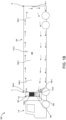
FIGs. 1A and1B show an air conditioning and refrigeration system "system" for a container equipped with a transport refrigeration unit (TRU). -
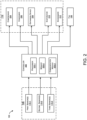
FIG. 2 shows a block diagram of the system ofFIGs. 1A and1B . -
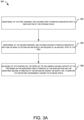
FIG. 3A shows a method for conditioning a conservation space of a container equipped with TRU. - FIG. 4A shows a flow diagram depicting the control strategy of the controller of
FIGs. 1A to 2 . - The following is a detailed description of embodiments of the invention depicted in the accompanying drawings. The embodiments are in such detail as to clearly communicate the invention. However, the amount of detail offered is not intended to limit the anticipated variations of embodiments; on the contrary, the intention is to cover all modifications and alternatives falling within the scope of the invention as set out in the appended claims.
- Various terms are used herein. To the extent a term used in a claim is not defined below, it should be given the broadest definition persons in the pertinent art have given that term as reflected in printed publications and issued patents at the time of filing.
- In the specification, reference may be made to the spatial relationships between various components and to the spatial orientation of various aspects of components as the devices are depicted in the attached drawings. However, as will be recognized by those skilled in the art after a complete reading of the disclosure, the components of this invention described herein may be positioned in any desired orientation. Thus, the use of terms such as "above," "below," "upper," "lower," "first", "second" or other like terms to describe a spatial relationship between various components or to describe the spatial orientation of aspects of such components should be understood to describe a relative relationship between the components or a spatial orientation of aspects of such components.
- Trailer refrigeration units (TRUs) may be employed in a container or trailer of vehicles to supply conditioned air within the container for maintaining a conditioned environment inside the storage space of the container. Various products including but not limited to pharmaceutical and nutraceutical products, and perishable items such as foods and beverages may be stored and transported in containers equipped with the TRU. These products are to be maintained at a specific temperature and/or humidity while transportation to keep them in a healthy condition and comply with product compliance regulations. Accordingly, based on the products being stored or transported in the container, the cooling capacity of the TRU may be adjusted to supply conditioned air within the storage space for maintaining the conditioned environment inside the storage space. However, the TRU may not be able to effectively monitor the environment of the entire storage space and further fail to sufficiently supply conditioned air throughout the storage space, especially towards a rear section of the container. As a result, the environment inside the container may not be homogeneously conditioned as per product compliance regulations, which may affect the stored products. There is therefore a need to maintain a homogenous and conditioned environment throughout the storage space in the container as per product compliance regulations.
- This invention overcomes the above-mentioned shortcomings and limitations associated with the existing containers equipped with TRUs, by providing an improved, automated, cost-effective, and efficient air conditioning and refrigeration system and method for containers equipped with a TRU, which effectively monitors the environment of the entire storage space of the container and further maintains a homogenous and conditioned environment throughout the storage space as well as at the rear section of the container.
- Referring to
FIGs. 1A to 2 , an air conditioning and refrigeration system "system" 100 for a container (trailer) 102 equipped with a transport refrigeration unit (TRU) 104 is disclosed, which may be configured to maintain a predefined homogenous environment across an entire enclosed (storage or conservation)space 106, including a rear section 106-1, associated with the container/trailer 102. Various products including but not limited to pharmaceutical and nutraceutical products, and perishable items such as foods and beverages may be stored and transported in container/trailer 102. Thesystem 100 may keep these products may be maintained at a specific temperature and/or humidity while transportation to keep them in a healthy condition and comply with product compliance regulations. - The
TRU 104 may be installed on the container/trailer 102 associated with one or more vehicles including one or more of an electric truck, a semi-electric truck, and a non-electric truck such that theTRU 104 remains fluidically connected to the ambient and further gets fluidically connected to thestorage space 106 of the container/trailer 102. TheTRU 104 may include a housing having a return air inlet port 104-1, an ambient air inlet port 104-2, and an air outlet port 104-3. The return air inlet port 104-1 may be fluidically connected tostorage space 106 to receive return air and the ambient air inlet port 104-2 may be fluidically connected to ambient to receive ambient (outside) air. Further, the air outlet port 104-3 of theTRU 104 may be fluidically connected to thestorage space 106 of the container/trailer 102. - In one or more embodiments, based on the predetermined environment to be maintained in the
storage space 106 or as per product compliance regulations, theTRU 104 may be operated to ingress the return air via the return inlet port 104-1 and/or ambient air via the ambient air inlet port 104-2 and degrees air (also referred to as exhaust air) into the storage space 106 (at a higher or lower temperature compared to the ingressed air (ambient air and/or return air) via the outlet port 104-3. For instance, the exhaust air from theTRU 104 may be warmer or hotter than the ingressed air (ambient air and/or return air) such that theTRU 104 may be employed to supply warm or hot air in thestorage space 106 of the container/trailer 102 to maintain the predetermined environment. In another instance, the exhaust air from theTRU 104 may be cooler than the received air such that theTRU 104 may be employed to supply cool air in thecontainer 102 to maintain the predetermined environment. The detailed construction and operation of theTRU 104 have been explained in subsequent paragraphs. - The
system 100 may include a variable-speed fan 108 configured with or within theTRU 104, which may control the ingress of the return airflow into theTRU 104 via the return inlet port 104-1 or ambient airflow into theTRU 104 via the ambient inlet port 104-2 and further control the flow of conditioned exhaust air into thestorage space 106 of thecontainer 102 via the outlet port 104-3. Thesystem 100 may further include one or more first sensors 110-1 positioned at predefined positions at the rear section 106-1 of the storage (conservation)space 106 associated with thecontainer 102. The first sensors 110-1 may be positioned at the bottom, middle and upper regions of the rear section 106-1 of thestorage space 106. The first sensors 110-1 may be configured to monitor one or more first attributes associated with the rear section 106-1 of thestorage space 106. In addition, in some embodiments, additional sensors may be positioned throughout theconservation space 106. For instance, one or more second sensors 110-2 such as a return air sensor (RAT) may be positioned within thecontainer 102 orTRU 104 at the return air inlet port 104-1 of theTRU 104 to monitor second attributes associated with the return air being received by theTRU 104 and a supply air temperature (SAT) (not shown) may be positioned outside of thecontainer 102 orTRU 104 at the ambient air inlet port 104-2 to monitor second attributes associated with the outside (ambient) air being received by theTRU 104. Further, third sensors 110-3 may be positioned at the front and/or middle sections 106-2, 106-3 of thestorage space 106, such that the first sensors 110-1 and the third sensors 110-3 may effectively monitor the first attributes associated with theentire storage space 106. The third sensors 110-3 may be positioned at the bottom, middle and upper regions of the front section and middle section of thestorage space 106. As the third sensors may 110-3 not be effective in monitoring theentire storage space 106, however, it is to be appreciated that the first sensors 110-1 may enable the system 110 to monitor the environment of theentire storage space 106. Moreover, the monitoring of control temperature (i.e., the temperature of the return air or outside/ambient air) by second sensors 110-2 may enable thesystem 100 to restrict overcooling or overheating of the front or middle sections 106-2, 106-3 of thestorage space 106 while maintaining the predetermined environment at the rear section 106-1 of thestorage space 106. - In one or more embodiments, the first and second attributes may include one or more of temperature, humidity, and airflow rate, but is not limited to the like. Further, the predefined environment may include one or more of a predefined temperature range, a predefined humidity range, and a predefined airflow speed range, but is not limited to the like, to be maintained in the
storage space 106. - The
system 100 may further include acontroller 202 in communication with the first sensors 110-1, the second sensors 110-2, the third sensors 110-3, avapor compression system 112 of theTRU 104, and thevariable speed fan 108. In one or more embodiments, thecontroller 202 may be a control unit of theTRU 104. In other embodiments, thecontroller 202 may be in communication with a control unit of theTRU 104. The first sensors 110-1, the second sensors 110-2, and the third sensors 110-3 may be wireless sensors and/or wired sensors that may be connected to thecontroller 202 by wired or wireless media. Thecontroller 202 may be configured to adjust the speed of thefan 108 and/or cooling capacity of theTRU 104 based on the monitored first attributes of the rear section 106-1 and the monitored second attributes (or control temperature) of the return air and/or the outside (ambient) air, to maintain the predefined environment across theentire storage space 106. - In one or more embodiments, when the monitored temperature of the rear section 106-1 exceeds the predefined temperature range and the control temperature (temperature of the return air and/or the ambient air) is detected to be within the predefined temperature range, the
controller 202 may be configured to increase the speed of thefan 108 and/or operate thevapor compression system 112 to adjust the cooling capacity of theTRU 104 in order to maintain the predefined temperature range at the rear section 106-1, thereby creating a homogenous predetermined environment in theentire storage space 106. - In other embodiments, when the control temperature (temperature of the return air and/or the ambient air) is detected to be within the predefined temperature range and/or the monitored temperature of the rear section 106-1 is detected to be within the predefined temperature range, the
controller 202 may be configured to maintain the same cooling capacity of theTRU 104 and further maintain the speed of thefan 108 to maintain the predefined temperature range across thestorage space 106. - In an example, the predefined temperature range to be maintained in the rear section 106-1 of the
storage space 106 may be set as 5°C±2°C, where the set point temperature may be 5°C with a tolerance of 2°C. Further, the control temperature detected by the second sensors 110-2 may be 4°C. Furthermore, if the temperature of the rear section 106-1 is detected (by the first sensors 110-1) to be 5°C,controller 202 may identify a gap of 3°C between the detected temperature and the predefined temperature range of the rear section 106-1 as the tolerance is ±2°C. Accordingly, thecontroller 202 may increase the speed of thefan 108 and/or operate thevapor compression system 112 to increase the cooling capacity of theTRU 104 in order to maintain the predefined temperature range (5°C) in the rear section 106-1. - Referring to
FIG. 2 , thecontroller 202 can include a processor 202-1 coupled to a memory 202-2 storing instructions executable by the processor 202-1 to enable thecontroller 202 to perform one or more designated operations. The memory 202-2 of thecontroller 202 may contain predefined values for various operating parameters or attributes to be maintained within thecontainer 102 or thespace 106. The parameters and attributes may include but are not limited to, temperature set points for various locations within thecontainer 102 or thespace 106, pressure limits, current limits, engine speed limits, and any variety of other desired operating parameters or limits with theTRU 104. - The
controller 202 may control the operation of thevapor compression system 112 of theTRU 104 to adjust the cooling capacity of theTRU 104 based on the predetermined environment to be maintained in thestorage space 106. In one or more embodiments, thevapor compression system 112 may comprise acompressor 204, acondenser 206 configured downstream of thecompressor 204, anexpansion device 208 configured downstream of thecondenser 206, and anevaporator 210 configured downstream of theexpansion device 208, enclosed within the housing of theTRU 104 having the inlet port 104-1 and the outlet port 105-2. In addition, an outlet of thecompressor 204 may be fluidically connected to thecondenser 206. In one or more embodiments, thecompressor 204 may be a variable-speed scroll compressor, however, other compressors such as reciprocating or screw compressors are possible without limiting the scope of the invention. A motor (not shown) may be used to drive thecompressor 204. For example, a motor can be an integrated electric drive motor driven by a synchronous generator, a commercial power service an external power generation system (e.g., shipboard), a generator or the like. Thecompressor 204 may also be a multi-stage compression device. - In one or more embodiments, referring back to
FIGs. 1A and1B , theTRU 104 may be coupled to the front end (F) of the container/trailer 102. The air outlet port 104-3 of the TRU may be in fluidic communication with thestorage space 106 of the container/trailer 102, the return inlet port 104-1 may be in fluidic communication with thestorage space 106, and the ambient inlet port 104-2 may be in fluidic communication with ambient. Further, thetrailer 102 may be coupled to a rear end of a cab ortruck 114 such that a gap remains therebetween. TheTRU 104 may be coupled to the front end (F) of the container/trailer 102 in the gap area between thecab 114 and container/trailer 102. Alternatively, in one or more embodiments, theTRU 104 may be coupled to a prescribed position on a side or more than one side of the container/trailer 102. Moreover, a plurality ofTRUs 104 can be coupled to a single container/trailer 102. Alternatively, asingle TRU 104 can be coupled to a plurality of container/trailers 102. - In one or more embodiments, referring back to
FIG. 2 , in a cooling mode or cooling cycle (i.e., when the cooling capacity of theTRU 104 is to be increased), theTRU 104 may circulate the refrigerant from thecompressor 204 to thecondenser 206, through theexpansion device 208 and theevaporator 210, and then return to thecompressor 204. high-temperature, highpressure refrigerant vapor exiting the outlet of thecompressor 204 may move to thecondenser 206 that may include a plurality of condenser coils, which may receive air blown by acondenser 206 fan 108 (not shown). Thecondenser 206 may facilitate heat exchange between the refrigerant flowing within thecondenser 206 coils and the received air to remove latent heat through thecondenser 206, which may condense the refrigerant to a high-pressure/high-temperature liquid within thecondenser 206 coils. The high-pressure/high-temperature liquid refrigerant may flow to a receiver that may provide storage for excess liquid refrigerant during low-temperature operations. Further, from the receiver, the refrigerant may flow to a filter drier which may keep the refrigerant clean and dry. - The
TRU 104 orvapor compression system 112 may further include aneconomizer 212 fluidically configured between thecompressor 204, the receiver, theevaporator 210, and thecondenser 206. In one or more embodiments, theexpansion device 208 may be an electronic evaporator expansion valve (EVXV). Theeconomizer 212 may increase the refrigerant subcooling. When theeconomizer 212 is active, an injection solenoid valve associated with theeconomizer 212 may open to allow refrigerant to pass through an auxiliary expansion valve having a sensing bulb located upstream of an intermediate inlet port of thecompressor 204. The injection solenoid valve may be controlled, responsive to the temperature measured at the bulb, and serve to expand and cool the refrigerant that proceeds into an economizer counter-flow heat exchanger that may additionally sub-cool the liquid refrigerant. - The refrigerant may flow from the economizer heat exchanger of the
economizer 212 to theEVXV 208. As the liquid refrigerant passes through the orifice of theEVXV 208, at least some of the liquid refrigerant may vaporize. The vaporized refrigerant may then enter theevaporator 210 via the distributor and then flow through the evaporator coils of theevaporator 210. Theevaporator 210 may absorb heat from the air (e.g., return air returning from thestorage space 106 or the outside/ambient air) to vaporize some or all of the remaining liquid refrigerant in theevaporator 210. The air may preferably be drawn or pushed across the evaporator coils by thefan 108. The refrigerant vapor may be drawn from theevaporator 210 through a suction service valve back into thecompressor 204 via an accumulator that may store any excess refrigerant. Further, a heat exchanger may be additionally configured in theTRU 104 to facilitate heat transfer from a warm refrigerant supplied by thecondenser 206 or the sub-cooled liquid from the economizer's heat exchanger to the cold refrigerant supplied by theevaporator 210 during the cooling cycle. Further, thevariable speed fan 108 may enable (increase or decrease) the flow of the air (ambient air and/or return air) through theTRU 104 while passing the air across the cold refrigerant-carrying evaporator coils to cool the air and further supply the cool exhaust air into thestorage space 106 via the outlet port 104-3, thereby maintaining the predetermined environment within theentire storage space 106 of the container/trailer 102. - In one or more embodiments, the
controller 202 can include a communication module 202-3 that can operatively couple thecontroller 202 to the first sensors 110-1, the second sensors 110-2, the third sensors 110-3, thevapor compression system 112 of theTRU 104, and thevariable speed fan 108, and further enable thecontroller 202 to receive temperature inputs, pressure inputs, and humidity levels from various points in thestorage space 106. In addition, thecontroller 202 can include an actuator, drive circuit, and relays to receive signals or current from thecontroller 202 and in turn control various internal components of theTRU 104, thefan 108, thevapor compression system 112 as well as external or peripheral devices in theTRU 104. - In one or more embodiments, the
fan 108 and theTRU 104 may be operatively coupled to an AC power source or a DC power source (collectively designated as 116, herein) associated with the vehicle. Thecontroller 202 may control the operation of thefan 108 and thevapor compression system 112 of theTRU 104 based on the available electrical power while maintaining the predetermined environment in thestorage space 106. In one or more embodiments, when thecontroller 202 calculates the available electrical power to go below a predefined level after a predefined time, which may affect maintaining the predetermined environment in thestorage space 106 after the predefined time, thecontroller 202 may accordingly transmit an alert signal to mobile devices associated with a user of the vehicle or a human-machine interface (HMI) installed in the vehicle. The alert signal may be indicative of a request for charging the power source of the vehicle and/or electrically connecting theTRU 104 and the system to an external power source. - Referring to
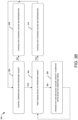
FIG. 3A ,method 300 for conditioning a storage space of a container/trailer equipped with a transport refrigeration unit (TRU) is disclosed. Further, referring toFIG. 3B , an exemplary flow diagram depicting the control strategy of the controller is disclosed.Method 300 may involve the first sensors 110-1, the second sensors 110-2, the third sensors 110-3, thevapor compression system 112 of theTRU 104, and thevariable speed fan 108.Method 300 may include step 302 of monitoring, by the first sensors, one or more first attributes associated with a rear section of the storage space. Further,method 300 may include step 304 of monitoring, by the second sensors, one or more second attributes associated with one or more of the return air, and the ambient air received at a return air inlet port and an ambient air inlet port, respectively, of the TRU. - In one or more embodiments,
method 300 may include the steps of positioning one or more third sensors at a front section and a middle section of the storage space. The third sensors may be configured to monitor the first attributes associated with the front section and the middle section of the storage space. -
Method 300 may further includestep 306 of adjusting, by the controller, the speed of the fan and/or cooling capacity of the TRU based on the monitored first attributes of the rear section and the monitored second attributes of the return air and/or the ambient air, to maintain the predefined environment across the storage space. In one or more embodiments, the method of adjusting the cooling capacity of the TRU may comprise the step of controlling, by the controller, the operation of the vapor compression system associated with the TRU to adjust the cooling capacity of the TRU. - In one or more embodiments, when the control temperature (temperature of the return air and/or the ambient air) is detected to be within the predefined temperature range, at
step 308, the controller may maintain the same cooling capacity in the TRU and further maintain the speed of the fan to maintain the predefined temperature range across the storage space - In one or more embodiments, when the control temperature (temperature of the return air and/or the ambient air) is detected to be within the predefined temperature range and the monitored temperature of the rear section is also detected to be within the predefined temperature range, at
step 310, the controller may maintain the same cooling capacity of the TRU and further maintain the same speed of the fan to maintain the predefined temperature range across the storage space. - In one or more embodiments, when the monitored temperature of the rear section exceeds the predefined temperature range and the control temperature (temperature of the return air and/or the ambient air) is detected to be within the predefined temperature range, at
step 306, the controller may increase the speed of the fan and adjust the cooling capacity of the TRU to maintain the predefined temperature range at the rear section of the storage space. - Thus, this invention overcomes the drawbacks, and limitations associated with the existing containers/trailers equipped with TRU, by providing an improved, automated, cost-effective, and efficient air conditioning and refrigeration system for containers equipped with a TRU. The invention effectively monitors the environment of the entire storage space of the container including the rear section of the storage space and further maintains a homogenous and conditioned environment throughout the storage space, thereby keeping the stored products healthy and meeting the product compliance regulations.
- The use of the term "homogenous environment" refers to a conditioned environment within the
storage space 106 where the temperature, humidity, and/or other environmental conditions associated with thestorage space 106 may be a numerical value having a variation less than or equal to ±10% of the numerical value, expressly including any narrow range within the given range of the numerical value as well as the exact numerical value. For example, a temperature of "about" 30° C refers to a temperature from 27° C to 33° C, but also expressly includes any narrower range of temperature or even a single temperature within that range, including, for example, a temperature of exactly 30° C. - While the invention has been described with reference to exemplary embodiments, it will be understood by those skilled in the art that various changes may be made without departing from the scope of the invention as set out in the appended claims. Modifications may be made to adopt a particular situation or material to the teachings of the invention without departing from the scope thereof. Therefore, it is intended that the invention not be limited to the particular embodiment disclosed, but that the invention includes all embodiments falling within the scope of the invention as set out in the appended claims.
- In interpreting the specification, all terms should be interpreted in the broadest possible manner consistent with the context. In particular, the terms "comprises" and "comprising" should be interpreted as referring to elements, components, or steps in a non-exclusive manner, indicating that the referenced elements, components, or steps may be present, or utilized, or combined with other elements, components, or steps that are not expressly referenced. Where the specification claims refer to at least one of something selected from the group consisting of A, B, C ....and N, the text should be interpreted as requiring only one element from the group, not A plus N, or B plus N, etc.
Claims (15)
- An air conditioning and refrigeration system (100) for a container (102) equipped with a transport refrigeration unit TRU (104), the system comprising:a variable speed fan (108) configured with the TRU;one or more first sensors (110-1) positioned at predefined positions at a rear section (106-1) of a conservation space (106) associated with the container, the one or more first sensors are configured to monitor one or more first attributes associated with the rear section; anda controller (202) in communication with the one or more first sensors and the fan, wherein the controller is configured to adjust speed of the fan and/or adjust cooling capacity of the TRU based on the monitored first attributes of the rear section, to maintain a predefined environment at the rear section or across the conservation space.
- The system (100) of claim 1, wherein the system comprises one or more second sensors (110-2) in communication with the controller (202) and configured to monitor one or more second attributes associated with one or more of return air received at a return air inlet port (104-1) of the TRU (104) and ambient air received at an ambient air inlet port (104-2) of the TRU,
wherein the controller is configured to adjust the speed of the fan (108) and/or cooling capacity of the TRU based on the monitored first attributes of the rear section (106-1) and the monitored second attributes of the return air and/or the ambient air, to maintain the predefined environment across the conservation space (106). - The system (100) of any of claims 1 and 2, wherein the controller (202) is operatively coupled to a vapor compression system (112) associated with the TRU (104), wherein the controller controls the operation of the vapor compression system to adjust the cooling capacity of the TRU.
- The system (100) of any of claims 2 and 3, wherein the one or more first and second attributes comprise one or more of temperature, humidity, and airflow rate, wherein the predefined environment comprises one or more of a predefined temperature range, a predefined humidity range, and a predefined airflow speed range.
- The system (100) of any preceding claim, wherein when the monitored temperature of the rear section (106-1) exceeds the predefined temperature range and the monitored temperature of the return air and/or the ambient air is within the predefined temperature range, the controller (202) is configured to increase the speed of the fan (108) and/or adjust the cooling capacity of the TRU (104) to maintain the predefined temperature range at the rear section.
- The system (100) of any preceding claim, wherein when the monitored temperature of the return air and/or the ambient air is within the predefined temperature range and/or the monitored temperature of the rear section (106-1) is within the predefined temperature range, the controller (202) is configured to maintain the cooling capacity of the TRU (104) and maintain the speed of the fan (108) to maintain the predefined temperature range across the conservation space (106).
- The system (100) of any preceding claim, wherein the one or more first sensors (110-1) are installed over and/or within one or more boxes storing one or more products at the rear section (106-1) of the container (102); and/or
wherein the one or more first sensors (110-1) are installed on an inner wall of the container (102) at the rear section (106-1) and/or disposed of in the conservation space (106). - The system (100) of any preceding claim, wherein the controller (202) is a control unit of the TRU (104); or
wherein the controller (202) is in communication with a control unit of the TRU (104). - The system (100) of any preceding claim, wherein the container (102) is a trailer associated with a vehicle, wherein the vehicle is one or more of an electric truck, a semi-electric truck, and a non-electric truck,
optionally wherein the fan (108) and the TRU (104) are operatively coupled to an AC power source or a DC power source (116) associated with the vehicle. - The system (100) of any preceding claim, wherein the system comprises one or more third sensors (110-3) positioned at a front section (106-2) and a middle section (106-3) of the conservation space (106), wherein the one or more first sensors (110-1) and the one or more third sensors monitor are configured to monitor the first attributes associated with the entire storage space.
- A method (300) for conditioning a conservation space (106) of a container (102) equipped with a transport refrigeration unit TRU (104), the method comprising the steps of:monitoring, by one or more first sensors (110-1), one or more first attributes associated with a rear section (106-1) of the conservation space; andadjusting, by a controller (202), speed of a variable speed fan (108) configured with the TRU and/or adjusting cooling capacity of the TRU based on the monitored first attributes of the rear section, to maintain a predefined environment at the rear section or across the conservation space.
- The method (300) of claim 11, wherein the method comprises the steps of:monitoring, by one or more second sensors (110-2), one or more second attributes associated with one or more of a return air received at a return air inlet port (104-1) of the TRU (104), and ambient air received at an ambient air inlet port (104-2) of the TRU; andadjusting, by the controller (202), speed of the fan (108) and/or cooling capacity of the TRU based on the monitored first attributes of the rear section and the monitored second attributes of the return air and/or the ambient air, to maintain the predefined environment across the conservation space (106).
- The method (300) of any of claim 11 and 12, wherein the controller (202) is operatively coupled to a vapor compression system (112) associated with the TRU (104), wherein the method comprises the step of controlling, by the controller, the operation of the vapor compression system to adjust the cooling capacity of the TRU.
- The method (300) of any of claims 11 to 13, wherein the method comprises the steps of monitoring, by one or more third sensors (110-3) positioned at a front section (106-2) and a middle section (106-3) of the storage space (106), the first attributes associated with the front section and the middle section of the storage space; and/or
wherein the one or more first and second attributes comprise one or more of temperature, humidity, and airflow rate, wherein the predefined environment comprises one or more of a predefined temperature range, a predefined humidity range, and a predefined airflow speed range. - The method (300) of any of claims 11 to 14, wherein when the monitored temperature of the rear section (106-1) exceeds the predefined temperature range and the monitored temperature of the return air and/or the ambient air is within the predefined temperature range, the method comprises the steps of increasing the speed of the fan (108) and/or adjusting the cooling capacity of the TRU (104) to maintain the predefined temperature range at the rear section; and/or
wherein when the monitored temperature of the return air and/or the ambient air is within the predefined temperature range and/or the monitored temperature of the rear section (106-1) is within the predefined temperature range, the method comprises the steps of maintaining the cooling capacity of the TRU (104) and maintaining the speed of the fan to maintain the predefined temperature range across the conservation space (106).
Applications Claiming Priority (1)
| Application Number | Priority Date | Filing Date | Title |
|---|---|---|---|
| US202363508947P | 2023-06-19 | 2023-06-19 |
Publications (2)
| Publication Number | Publication Date |
|---|---|
| EP4480723A1 true EP4480723A1 (en) | 2024-12-25 |
| EP4480723B1 EP4480723B1 (en) | 2025-10-29 |
Family
ID=91481709
Family Applications (1)
| Application Number | Title | Priority Date | Filing Date |
|---|---|---|---|
| EP24181523.2A Active EP4480723B1 (en) | 2023-06-19 | 2024-06-11 | Air conditioning and refrigeration system and method for container equipped with a transport refrigeration unit |
Country Status (3)
| Country | Link |
|---|---|
| US (1) | US20250052464A1 (en) |
| EP (1) | EP4480723B1 (en) |
| CN (1) | CN119159949A (en) |
Citations (2)
| Publication number | Priority date | Publication date | Assignee | Title |
|---|---|---|---|---|
| WO2011094099A1 (en) * | 2010-01-29 | 2011-08-04 | Carrier Corporation | Solar power assisted transport refrigeration systems, transport refigeration units and methods for same |
| US10696139B2 (en) * | 2016-03-07 | 2020-06-30 | Carrier Corporation | Return air intake grille de-icing method |
Family Cites Families (4)
| Publication number | Priority date | Publication date | Assignee | Title |
|---|---|---|---|---|
| US8286437B2 (en) * | 2010-06-30 | 2012-10-16 | Thermo King Corporation | Transport refrigeration system with predictive refrigeration |
| US20150352925A1 (en) * | 2012-12-28 | 2015-12-10 | Thermo King Corporation | Method and system for controlling operation of condenser and evaporator fans |
| US20210362567A1 (en) * | 2015-10-23 | 2021-11-25 | Ronald Koelsch | Zone isolation air flow system for semi-trailer reefers |
| EP3856561A1 (en) * | 2018-09-28 | 2021-08-04 | Carrier Corporation | Integrated charging port for refrigerated electrical or hybrid electrical truck |
-
2024
- 2024-06-10 US US18/738,259 patent/US20250052464A1/en active Pending
- 2024-06-11 EP EP24181523.2A patent/EP4480723B1/en active Active
- 2024-06-18 CN CN202410784712.0A patent/CN119159949A/en active Pending
Patent Citations (2)
| Publication number | Priority date | Publication date | Assignee | Title |
|---|---|---|---|---|
| WO2011094099A1 (en) * | 2010-01-29 | 2011-08-04 | Carrier Corporation | Solar power assisted transport refrigeration systems, transport refigeration units and methods for same |
| US10696139B2 (en) * | 2016-03-07 | 2020-06-30 | Carrier Corporation | Return air intake grille de-icing method |
Also Published As
| Publication number | Publication date |
|---|---|
| CN119159949A (en) | 2024-12-20 |
| EP4480723B1 (en) | 2025-10-29 |
| US20250052464A1 (en) | 2025-02-13 |
Similar Documents
| Publication | Publication Date | Title |
|---|---|---|
| EP2491318B1 (en) | Parameter control in transport refrigeration system and methods for same | |
| CN101600917B (en) | Method of operating a transport refrigeration unit with a remote evaporator | |
| EP2621744B1 (en) | Operation of transport refrigeration systems to prevent engine stall and overload | |
| JP4068905B2 (en) | Control method of refrigeration system | |
| EP1146299B1 (en) | Integrated electronic refrigerant management system | |
| EP3511653B1 (en) | Method of managing compressor start for a transport refrigeration system and corresponding transport refrigeration system | |
| EP1038703B1 (en) | Voltage control using engine speed | |
| ES2876283T3 (en) | Method and apparatus for calibrating an accelerator | |
| CN105008160B (en) | Method and system for controlling operation of condenser fans and evaporator fans | |
| CN103069230A (en) | Evaporator refrigerant saturated instant defrosting | |
| EP3680117B1 (en) | Methods and systems for energy efficient defrost of a transport climate control system evaporator | |
| WO2015105845A1 (en) | Adaptive control of multi-compartment transport refrigeration system | |
| US6141981A (en) | Superheat control for optimum capacity under power limitation and using a suction modulation valve | |
| CN111971203A (en) | Automatic transport refrigeration unit settings by real time location | |
| EP4480723B1 (en) | Air conditioning and refrigeration system and method for container equipped with a transport refrigeration unit | |
| US20240361064A1 (en) | Transport refrigeration unit and refrigeration circuit with refrigerant-based defrost control and a method thereof | |
| US20250001835A1 (en) | Method and system for evaluating condition of perishable goods using digital twin | |
| US20240361066A1 (en) | Transport refrigeration unit with multi-heating mode and refrigerant-based defrost control | |
| EP4303503A1 (en) | Multi-compartment transport refrigeration system | |
| EP3905161B1 (en) | Data integrity of verification data for a transport climate control system | |
| EP4234290B1 (en) | Transport refrigeration system powered by a fuel cell | |
| CN112334717A (en) | Multi-temperature transport refrigeration system and method | |
| CN121716473A (en) | Control method and device of vehicle-mounted cold and warm box, vehicle-mounted cold and warm box and storage medium | |
| JPS62248963A (en) | Air conditioner | |
| HK1172943B (en) | Parameter control in transport refrigeration system and methods for same |
Legal Events
| Date | Code | Title | Description |
|---|---|---|---|
| PUAI | Public reference made under article 153(3) epc to a published international application that has entered the european phase |
Free format text: ORIGINAL CODE: 0009012 |
|
| STAA | Information on the status of an ep patent application or granted ep patent |
Free format text: STATUS: THE APPLICATION HAS BEEN PUBLISHED |
|
| AK | Designated contracting states |
Kind code of ref document: A1 Designated state(s): AL AT BE BG CH CY CZ DE DK EE ES FI FR GB GR HR HU IE IS IT LI LT LU LV MC ME MK MT NL NO PL PT RO RS SE SI SK SM TR |
|
| STAA | Information on the status of an ep patent application or granted ep patent |
Free format text: STATUS: REQUEST FOR EXAMINATION WAS MADE |
|
| 17P | Request for examination filed |
Effective date: 20250218 |
|
| GRAP | Despatch of communication of intention to grant a patent |
Free format text: ORIGINAL CODE: EPIDOSNIGR1 |
|
| STAA | Information on the status of an ep patent application or granted ep patent |
Free format text: STATUS: GRANT OF PATENT IS INTENDED |
|
| RIC1 | Information provided on ipc code assigned before grant |
Ipc: F25D 27/00 20060101ALI20250514BHEP Ipc: F25D 21/00 20060101ALI20250514BHEP Ipc: F25D 11/00 20060101ALI20250514BHEP Ipc: B60H 1/32 20060101ALI20250514BHEP Ipc: F25D 29/00 20060101ALI20250514BHEP Ipc: F25D 17/06 20060101ALI20250514BHEP Ipc: B60H 1/00 20060101AFI20250514BHEP |
|
| INTG | Intention to grant announced |
Effective date: 20250526 |
|
| GRAS | Grant fee paid |
Free format text: ORIGINAL CODE: EPIDOSNIGR3 |
|
| GRAA | (expected) grant |
Free format text: ORIGINAL CODE: 0009210 |
|
| STAA | Information on the status of an ep patent application or granted ep patent |
Free format text: STATUS: THE PATENT HAS BEEN GRANTED |
|
| AK | Designated contracting states |
Kind code of ref document: B1 Designated state(s): AL AT BE BG CH CY CZ DE DK EE ES FI FR GB GR HR HU IE IS IT LI LT LU LV MC ME MK MT NL NO PL PT RO RS SE SI SK SM TR |
|
| REG | Reference to a national code |
Ref country code: CH Ref legal event code: F10 Free format text: ST27 STATUS EVENT CODE: U-0-0-F10-F00 (AS PROVIDED BY THE NATIONAL OFFICE) Effective date: 20251029 Ref country code: GB Ref legal event code: FG4D |
|
| REG | Reference to a national code |
Ref country code: DE Ref legal event code: R096 Ref document number: 602024001086 Country of ref document: DE |
|
| REG | Reference to a national code |
Ref country code: NL Ref legal event code: FP Ref country code: IE Ref legal event code: FG4D |
|
| PG25 | Lapsed in a contracting state [announced via postgrant information from national office to epo] |
Ref country code: ES Free format text: LAPSE BECAUSE OF FAILURE TO SUBMIT A TRANSLATION OF THE DESCRIPTION OR TO PAY THE FEE WITHIN THE PRESCRIBED TIME-LIMIT Effective date: 20251029 |
|
| REG | Reference to a national code |
Ref country code: LT Ref legal event code: MG9D |
|
| PG25 | Lapsed in a contracting state [announced via postgrant information from national office to epo] |
Ref country code: NO Free format text: LAPSE BECAUSE OF FAILURE TO SUBMIT A TRANSLATION OF THE DESCRIPTION OR TO PAY THE FEE WITHIN THE PRESCRIBED TIME-LIMIT Effective date: 20260129 |
|
| PG25 | Lapsed in a contracting state [announced via postgrant information from national office to epo] |
Ref country code: HR Free format text: LAPSE BECAUSE OF FAILURE TO SUBMIT A TRANSLATION OF THE DESCRIPTION OR TO PAY THE FEE WITHIN THE PRESCRIBED TIME-LIMIT Effective date: 20251029 Ref country code: AT Free format text: LAPSE BECAUSE OF FAILURE TO SUBMIT A TRANSLATION OF THE DESCRIPTION OR TO PAY THE FEE WITHIN THE PRESCRIBED TIME-LIMIT Effective date: 20251029 Ref country code: FI Free format text: LAPSE BECAUSE OF FAILURE TO SUBMIT A TRANSLATION OF THE DESCRIPTION OR TO PAY THE FEE WITHIN THE PRESCRIBED TIME-LIMIT Effective date: 20251029 |
|
| REG | Reference to a national code |
Ref country code: AT Ref legal event code: MK05 Ref document number: 1851186 Country of ref document: AT Kind code of ref document: T Effective date: 20251029 |
|
| PG25 | Lapsed in a contracting state [announced via postgrant information from national office to epo] |
Ref country code: RS Free format text: LAPSE BECAUSE OF FAILURE TO SUBMIT A TRANSLATION OF THE DESCRIPTION OR TO PAY THE FEE WITHIN THE PRESCRIBED TIME-LIMIT Effective date: 20260129 |
|
| PG25 | Lapsed in a contracting state [announced via postgrant information from national office to epo] |
Ref country code: IS Free format text: LAPSE BECAUSE OF FAILURE TO SUBMIT A TRANSLATION OF THE DESCRIPTION OR TO PAY THE FEE WITHIN THE PRESCRIBED TIME-LIMIT Effective date: 20260228 |
|
| PG25 | Lapsed in a contracting state [announced via postgrant information from national office to epo] |
Ref country code: PT Free format text: LAPSE BECAUSE OF FAILURE TO SUBMIT A TRANSLATION OF THE DESCRIPTION OR TO PAY THE FEE WITHIN THE PRESCRIBED TIME-LIMIT Effective date: 20260302 |
|
| PG25 | Lapsed in a contracting state [announced via postgrant information from national office to epo] |
Ref country code: PL Free format text: LAPSE BECAUSE OF FAILURE TO SUBMIT A TRANSLATION OF THE DESCRIPTION OR TO PAY THE FEE WITHIN THE PRESCRIBED TIME-LIMIT Effective date: 20251029 |
|
| PG25 | Lapsed in a contracting state [announced via postgrant information from national office to epo] |
Ref country code: LV Free format text: LAPSE BECAUSE OF FAILURE TO SUBMIT A TRANSLATION OF THE DESCRIPTION OR TO PAY THE FEE WITHIN THE PRESCRIBED TIME-LIMIT Effective date: 20251029 |
|
| PG25 | Lapsed in a contracting state [announced via postgrant information from national office to epo] |
Ref country code: BG Free format text: LAPSE BECAUSE OF FAILURE TO SUBMIT A TRANSLATION OF THE DESCRIPTION OR TO PAY THE FEE WITHIN THE PRESCRIBED TIME-LIMIT Effective date: 20251029 |