EP4480719A1 - Detection of uneven or irregular treadwear - Google Patents
Detection of uneven or irregular treadwear Download PDFInfo
- Publication number
- EP4480719A1 EP4480719A1 EP24182729.4A EP24182729A EP4480719A1 EP 4480719 A1 EP4480719 A1 EP 4480719A1 EP 24182729 A EP24182729 A EP 24182729A EP 4480719 A1 EP4480719 A1 EP 4480719A1
- Authority
- EP
- European Patent Office
- Prior art keywords
- tire
- tread
- sensor
- pair
- conductive filament
- Prior art date
- Legal status (The legal status is an assumption and is not a legal conclusion. Google has not performed a legal analysis and makes no representation as to the accuracy of the status listed.)
- Granted
Links
Images



Classifications
-
- B—PERFORMING OPERATIONS; TRANSPORTING
- B60—VEHICLES IN GENERAL
- B60C—VEHICLE TYRES; TYRE INFLATION; TYRE CHANGING; CONNECTING VALVES TO INFLATABLE ELASTIC BODIES IN GENERAL; DEVICES OR ARRANGEMENTS RELATED TO TYRES
- B60C11/00—Tyre tread bands; Tread patterns; Anti-skid inserts
- B60C11/24—Wear-indicating arrangements
- B60C11/243—Tread wear sensors, e.g. electronic sensors
-
- B—PERFORMING OPERATIONS; TRANSPORTING
- B60—VEHICLES IN GENERAL
- B60C—VEHICLE TYRES; TYRE INFLATION; TYRE CHANGING; CONNECTING VALVES TO INFLATABLE ELASTIC BODIES IN GENERAL; DEVICES OR ARRANGEMENTS RELATED TO TYRES
- B60C23/00—Devices for measuring, signalling, controlling, or distributing tyre pressure or temperature, specially adapted for mounting on vehicles; Arrangement of tyre inflating devices on vehicles, e.g. of pumps or of tanks; Tyre cooling arrangements
- B60C23/02—Signalling devices actuated by tyre pressure
- B60C23/04—Signalling devices actuated by tyre pressure mounted on the wheel or tyre
- B60C23/0491—Constructional details of means for attaching the control device
- B60C23/0493—Constructional details of means for attaching the control device for attachment on the tyre
-
- G—PHYSICS
- G01—MEASURING; TESTING
- G01B—MEASURING LENGTH, THICKNESS OR SIMILAR LINEAR DIMENSIONS; MEASURING ANGLES; MEASURING AREAS; MEASURING IRREGULARITIES OF SURFACES OR CONTOURS
- G01B7/00—Measuring arrangements characterised by the use of electric or magnetic techniques
- G01B7/26—Measuring arrangements characterised by the use of electric or magnetic techniques for measuring depth
-
- G—PHYSICS
- G01—MEASURING; TESTING
- G01M—TESTING STATIC OR DYNAMIC BALANCE OF MACHINES OR STRUCTURES; TESTING OF STRUCTURES OR APPARATUS, NOT OTHERWISE PROVIDED FOR
- G01M17/00—Testing of vehicles
- G01M17/007—Wheeled or endless-tracked vehicles
- G01M17/02—Tyres
-
- B—PERFORMING OPERATIONS; TRANSPORTING
- B60—VEHICLES IN GENERAL
- B60C—VEHICLE TYRES; TYRE INFLATION; TYRE CHANGING; CONNECTING VALVES TO INFLATABLE ELASTIC BODIES IN GENERAL; DEVICES OR ARRANGEMENTS RELATED TO TYRES
- B60C19/00—Tyre parts or constructions not otherwise provided for
- B60C2019/004—Tyre sensors other than for detecting tyre pressure
Definitions
- the tire In the manufacture of a pneumatic tire, the tire is typically built on the drum of a tire-building machine, which is known in the art as a tire building drum. Numerous tire components are wrapped about and/or applied to the drum in sequence, forming a cylindrical-shaped tire carcass. The tire carcass is then expanded into a toroidal shape for receipt of the remaining components of the tire, such as a belt package and a rubber tread. The completed toroidally-shaped unvulcanized tire carcass, which is known in the art at that stage as a green tire, is then inserted into a mold or press for forming of the tread pattern and curing or vulcanization.
- treadwear can be indicative of other issues with a vehicle. Uneven treadwear on a tire may indicate an improper alignment, overinflation, underinflation, or potentially an issue with the vehicle's suspension.
- the invention relates to a tire in accordance with claim 1 or 2 respectively, and to a method in accordance with claim 11.
- Axial and “axially” mean lines or directions that are parallel to the axis of rotation of the tire.
- Bead means that part of the tire comprising an annular tensile member wrapped by ply cords and shaped, with or without other reinforcement elements such as flippers, chippers, apexes, toe guards and chafers, to fit the design rim.
- Carcass means the tire structure apart from the belt structure, tread, undertread, and sidewall rubber over the plies, but including the beads.
- “Circumferential” means lines or directions extending along the perimeter of the surface of the annular tread perpendicular to the axial direction.
- Innerliner means the layer or layers of elastomer or other material that form the inside surface of a tubeless tire and that contain the inflating fluid within the tire.
- “Lateral” means an axial direction.
- “Lateral edges” means a line tangent to the axially outermost tread contact patch or footprint as measured under normal load and tire inflation, the lines being parallel to the equatorial centerplane.
- Ring and radially mean lines or directions that are perpendicular to the axis of rotation of the tire.
- TPMS means a tire pressure monitoring system, which is an electronic system that measures the internal pressure of a tire and is capable of communicating the pressure to a processor that is mounted on the vehicle and/or is in electronic communication with electronic systems of the vehicle.
- Thread element or “traction element” means a rib or a block element defined by a shape having adjacent grooves.
- the data can be communicated to electronic systems of the vehicle, such as vehicle stability and/or braking systems, in order to provide improved control of the vehicle and to monitor or track driving behavior.
- electronic systems of the vehicle such as vehicle stability and/or braking systems
- Mechanical tread wear indicators are not able to provide such data to electronic systems of the vehicle.
- direct tire wear sensors are often difficult to install in the tire. Some direct wear sensors cannot withstand the harsh operating environment of the tire for a prolonged period, such as the recommended life of the tire. Other direct wear sensors are not capable of maintaining precise and repeatable indication of tire wear over the recommended life of the tire. Still other treadwear sensors are only capable of detecting wear in one area of the tread and cannot detect uneven and/or irregular wear.
- a conductive filament can be included in the tread of a tire at a wear depth. Connecting the ends of the conductive filament to an electrically active sensor allows a current to flow through the conductive filament. When the tread has worn down to the wear depth, the conductive filament will break, and current will cease to flow through the sensor. The break in current can trigger an alert that the tire needs to be changed or retreaded. By extending the conductive filament across the width of the tread, uneven or irregular wear will also cause the conductive filament to break, tripping the sensor. In addition, the conductive filament can extend circumferentially around the tread, enhancing the coverage of the treadwear sensor.
- a vehicle 100 is shown with one or more tires 103.
- Each tire 103 includes a partially embedded treadwear sensor 106.
- the treadwear sensor 106 is a component of a tire pressure monitoring system (TPMS).
- TPMS tire pressure monitoring system
- each one of the tires 103 on the vehicle 100 includes one or more of the treadwear sensors 106.
- the vehicle 100 is depicted as a commercial truck, the vehicle 100 may comprise any type of vehicle that employs tires where the commercial truck is presented as an example. To this end, the vehicle 100 may comprise other vehicles falling into various categories such as passenger vehicles, off-road vehicles, and the like, in which such vehicles include a greater or lesser number of tires 103 than are shown in FIG. 1 .
- the tire 103 includes a pair of bead areas 109, each one of which is formed with a bead core 113 that is embedded in the respective bead area 109.
- Each one of a pair of sidewalls 116 extends radially outwardly from a respective bead area 109 to a ground-contacting tread 119.
- the tread 119 is formed with multiple tread elements or tread blocks 123 and defines a radially outer surface 126.
- the tire 103 is reinforced by a carcass 129 that toroidally extends from one bead area 109 to the other bead area 109.
- An innerliner 133 is formed on the inner or inside surface of the carcass 129.
- the tire 103 is mounted on the flange of a wheel or rim forming an internal cavity 136.
- a treadwear sensor 106 is mounted to and partially embedded in the tire 103.
- the treadwear sensor 106 detects the wear of the tread 119 of the tire 103 but may additionally include a pressure sensor to sense the inflation pressure within a cavity 136 of the tire 103, and/or a temperature sensor to sense the temperature of the tire 103 and/or the cavity 136 of the tire 103.
- the treadwear sensor 106 is coupled to a commercially available tire pressure monitoring system (TPMS) module or other sensing unit.
- TPMS tire pressure monitoring system
- the treadwear sensor 106 comprises a processor and memory to store tire identification (ID) information for each specific tire 103.
- the tire ID may include manufacturing information for the tire 103, including the tire model; size information, such as rim size, width, and outer diameter; manufacturing location; manufacturing date; a treadcap code that includes or correlates to a compound identification; a mold code that includes or correlates to a tread structure identification, or other information.
- the tire ID may also include a service history or other information to identify specific features and parameters of each tire 103.
- the treadwear sensor 106 further includes an antenna for wirelessly transmitting measured parameters and tire ID data to a remote processor for analysis, such as a processor integrated into a vehicle electronic control unit and/or a Controller Area Network (CAN) bus associated with the vehicle 100.
- a remote processor for analysis such as a processor integrated into a vehicle electronic control unit and/or a Controller Area Network (CAN) bus associated with the vehicle 100.
- CAN Controller Area Network
- the treadwear sensor 106 may comprise a conductive filament 139 and a sensor unit 143 which is mounted to the tire 103 using a container 146.
- the container 146 receives the sensor unit 143 and is attached to the innerliner 133 by an adhesive, although the sensor unit 143 may be attached in some other manner or may be integrally molded as part of the innerliner 133 of the tire 103.
- the container 146 is flexible and is formed of an elastomer or polymer.
- the conductive filament 139 is disposed in the tread 119 at a wear depth. The wear depth is a predetermined distance below the radially outer surface 126 of the tread 119, which may correspond to a minimum recommended tread depth.
- the conductive filament 139 includes a pair of ends, each of which terminates in a sensor contact.
- the conductive filament 139 may be a wire, a conductive polymer, a carbon fiber wire, or other conductive material.
- the sensor unit 143 includes a rigid housing 149 formed with a base 153.
- a pair of electrical contacts 156 are mounted on the base 153 and extend through the housing 149.
- the sensor contacts at the ends of the conductive filament 139 can be attached to the electrical contacts 156 of the sensor unit 143.
- a continuous electrical circuit is formed by the conductive filament 139 and the connection of each sensor contact with each respective electrical contact 156 of the sensor unit 143.
- an elastomeric connector may be positioned between the sensor contacts of the conductive filament 139 and the electrical contacts 156 to ensure a reliable electrical connection therebetween over time. Such elastomeric connectors are generally commercially available.
- an elastomeric connector may be employed to electrically couple some other electrical contacts associated with the sensor unit 143 other than the electrical contacts 156 to the sensor contacts.
- various points on a circuit board that makes up part of the sensor unit 143 may be electrically coupled to the sensor contacts by way of an elastomeric connector.
- Such elastomeric connector may be compressed between various electrical contact points regardless of the material from which such electrical contact points are constructed.
- the materials may comprise metal, carbon fiber, conductive rubber compositions, or other materials.
- the conductive filament 139 When the conductive filament 139 is attached to the sensor unit 143, an electrical current flows through the conductive filament 139. When the tread is worn to the wear depth, the conductive filament 139 is exposed and will break. The electrical current stops flowing through the conductive filament 139, and the treadwear sensor 106 can be configured to trigger an alert, such as a notification, a warning light, or some other alert.
- an alert such as a notification, a warning light, or some other alert.
- the tire 103 includes a tread 119 comprising multiple tread elements 123.
- the tread 119 is positioned adjacent to, and radially outward relative to, an undertread 159.
- the tire 103 includes a carcass 129 and an innerliner 133, along with other components as can be appreciated.
- the tire may also include a treadwear sensor 106.
- the treadwear sensor 106 extends through the various components of the tire, with a sensor unit 143 being attached to the innerliner 133 of the tire 103 and a conductive filament 139 disposed within the tread 119.
- the conductive filament 139 is arranged in a wave-like pattern to provide additional flexibility. In other embodiments, the conductive filament 139 is arranged in a substantially linear form through the tread 119. Although the conductive filament 139 is shown in FIG. 4 as being disposed beneath the tread elements 123, it is understood that the conductive filament 139 may run through multiple tread elements 123. Additionally, although the conductive filament 139 is shown in FIG. 4 as extending through the tread 119 in a lateral direction, it is understood that, in some embodiments, the conductive filament 139 extends through the tread 119 in a circumferential direction around the tire 103.
- the tire 103 may include a chimney 163 that extends from the undertread 159 to the radially outer surface 126 of the tire 103 defined by the tread 119.
- the chimney 163 includes a chimney outer surface 166 that is generally flush with the radially outer surface 126 of the tire 103 and respective tread elements 123 in which the chimney 163 is disposed.
- the chimney 163 is shown in FIG. 5 as positioned within a single tread element 123, it is understood that the chimney 163 may run through multiple tread elements 123.
- the chimney 163 establishes a conductive pathway from the conductive undertread 159 to the ground upon which the vehicle 100 travels.
- the ground includes all elements upon which a vehicle may travel including pavement, cement, steel (bridges), dirt, rocks, or any other elements as can appreciated.
- the term ground as contemplated herein refers to an electrical ground as well as a physical ground upon which a vehicle rests.
- the tire 103 includes a conductive pathway established with conductive materials from the hubs of a vehicle 100 through the sidewalls 116 to the undertread 159.
- the chimney 163 completes the circuit by providing a conductive pathway from the undertread 159 to the terrestrial medium upon which the vehicle travels.
- the chimney 163 provides a conductive pathway through the tread 119 through which such a static charge can be discharged to ground. This prevents the buildup of large static charges in the vehicle 100 relative to the ground.
- the lateral position of the chimney 163 may vary depending on the locations of the tread elements 123 of a given tire 103. In one embodiment, the chimney 163 is located at a lateral position on the tread 119 so as to maximize the contact between the outer surface of the chimney 163 and the ground. In one embodiment, the chimney 163 may be positioned so that a center of the chimney 163 coincides with an equatorial plane of the tire 103.
- the tire 103 includes a predefined minimum tread depth. As a tire 103 is put into service on a vehicle 100 over time, the tread 119 will wear down.
- the predefined minimum tread depth is a minimum recommended tread depth at which the tire 103 can be placed into service. Once the tread 119 wears below the predefined minimum tread depth, then the tire 103 should be taken out of service.
- the tread 119 of the tire 103 thus includes a sacrificial portion that is expected to wear away over time while the tire 103 is in service.
- the conductive filament 139 is positioned at a predefined depth with respect to the outer surface of the tread element 123 of the tread 119. In one embodiment, this conductive filament 139 is positioned within the sacrificial portion of the tread 119 such that when the entire radially outermost portion is worn away, the continuity of the conductive filament 139 is compromised and detected by the sensor unit 143.
- the conductive filament 139 may be positioned at any depth in the tread 119 so as to detect wear of the tread 119 at various heights.
- the conductive filament 139 is positioned relative to the predefined minimum tread depth such that when the conductive filament 139 has worn away, the tread 119 will have been worn down to the predefined minimum tread depth. The sensor unit 143 can thus detect when the tire 103 has reached maximum wear and should be taken out of service.
- the sensor unit 143 detects the break in the electrical circuit and can wirelessly transmit a notice that the electrical circuit has broken and/or that a predefined minimum tread depth has been reached.
- the notice transmitted by the sensor unit 143 may be sent to a remote processor, such as a processor that is integrated into a vehicle electronic control unit, CAN bus, and/or a cloud-based server. The notice, by communicating that the minimum tread depth has been reached, thus indicates when replacement or retreading of the tire 103 should take place.
- the tire 103 with the treadwear sensor 106 indicates tire wear with components that are mounted within the tire 103 and does not require sensors that are external to the tire.
- the tire 103 with the treadwear sensor 106 provides a direct wear sensor system for a vehicle tire 103 that includes a structure which is easy to install in the tire 103, withstands the operating environment of the tire 103, accurately indicates tire wear in a repeatable manner, is capable of detecting irregular tread wear, and is capable of transmitting a wear indication to an electronic control system of the vehicle 100.
- the present disclosure also includes a method of determining wear of a tire using a treadwear sensor 106, and a method of forming a tire with a treadwear sensor 106 for indicating tread depth. Each method includes steps in accordance with the description that is presented above and shown in FIGS. 1 through 5 .
- a method for manufacturing a tire may include attaching a conductive filament 139 to an uncured tire carcass 129.
- the conductive filament 139 has a pair of ends extending through the uncured tire carcass 129 to an innerliner 133, the pair of ends terminating into a corresponding pair of sensor contacts.
- the method may include layering a tread cap on the uncured tire carcass 129 over the conductive filament 139.
- the method includes curing the uncured tire carcass 129 to produce a cured tire 103.
- the method may further include attaching the conductive filament 139 to the uncured tire carcass 129 using an adhesive.
- the conductive filament 139 is attached to the uncured tire carcass 129 by stitching the conductive filament 139 into the uncured tire carcass 129.
- the method may further include the step of attaching a sensor to the innerliner 133 of the cured tire 103.
- the sensor has a pair of electrical contacts 156, each of the electrical contacts 156 being in electrical contact with a corresponding one of the sensor contacts.
- the method further includes electrifying the sensor such that an electrical current flows from the sensor contacts through the conductive filament 139.
- the method further includes the step of attaching a plurality of conductive filaments 139 to an uncured tire carcass 129.
- the method may additionally include positioning the plurality of conductive filaments 139 around a circumference of the uncured tire carcass 129.
- a single treadwear sensor 106 may be disposed in the tread 119 of the tire 103, or multiple treadwear sensors 106 may be disposed in the tread 119 about the tire 103.
- the treadwear sensor 106 may be inserted into the tread element 123 before or after curing of the tire 103.
- the treadwear sensor 106 may include multiple conductive filaments 139, each one having a distal end spaced apart from the other wires, which enables the treadwear sensor 106 to indicate different wear states of the tread 119, without affecting the overall concept or operation of the various embodiments.
- each individual one of such conductive filaments 139 may be placed at various positions on a given tread 119 of the tire 130.
- a given conductive filament 139 falls within the footprint of the tire 103 at any given time. That is to say, a lesser number of conductive filaments 139 may be employed where a given conductive filament 139 falls within the footprint of a tire 103 as the tire 103 rotates, where a period of time exists between when a given conductive filament 139 leaves the footprint and another conductive filament 139 enters the footprint. Indeed, in one embodiment, a given tire 103 may only include a single conductive filament 139.
Landscapes
- Engineering & Computer Science (AREA)
- Mechanical Engineering (AREA)
- Physics & Mathematics (AREA)
- General Physics & Mathematics (AREA)
- Tires In General (AREA)
Abstract
Description
- In the manufacture of a pneumatic tire, the tire is typically built on the drum of a tire-building machine, which is known in the art as a tire building drum. Numerous tire components are wrapped about and/or applied to the drum in sequence, forming a cylindrical-shaped tire carcass. The tire carcass is then expanded into a toroidal shape for receipt of the remaining components of the tire, such as a belt package and a rubber tread. The completed toroidally-shaped unvulcanized tire carcass, which is known in the art at that stage as a green tire, is then inserted into a mold or press for forming of the tread pattern and curing or vulcanization.
- As tires are used on a vehicle, the rubber in the tread gradually breaks away causing the tread to become shallower and decreasing overall tire performance. When the tread is too shallow, the tire may become unsafe in certain driving conditions. For example, shallow tread decreases traction in wet or icy conditions. Further, shallow tread may impact braking distance and the likelihood of having a tire blowout. In addition to causing unsafe driving conditions, treadwear can be indicative of other issues with a vehicle. Uneven treadwear on a tire may indicate an improper alignment, overinflation, underinflation, or potentially an issue with the vehicle's suspension.
- The invention relates to a tire in accordance with claim 1 or 2 respectively, and to a method in accordance with claim 11.
- Dependent claims refer to preferred embodiments of the invention.
- Many aspects of the present disclosure can be better understood with reference to the following drawings. The components in the drawings are not necessarily to scale, with emphasis instead being placed upon clearly illustrating the principles of the disclosure. Moreover, in the drawings, like reference numerals designate corresponding parts throughout the several views.
-
FIG. 1 is a drawing of a vehicle with one or more tires that include a treadwear sensor according to various embodiments of the present disclosure. -
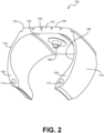
FIG. 2 is a perspective cross-sectional view of a tire shown inFIG. 1 according to various embodiments of the present disclosure. -
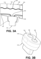
FIG. 3A is an enlarged schematic perspective view of a tire shown inFIG. 2 according to various embodiments of the present disclosure.FIG. 3B is a perspective view of a sensor employed in the exemplary embodiment of the tire with a treadwear sensor ofFIG. 2 according to various embodiments of the present disclosure. -
FIG. 4 is a partial cross-sectional perspective view of a portion of a tire ofFIG. 1 including a treadwear sensor according to various embodiments of the present disclosure. -
FIG. 5 is a partial cross-sectional perspective view of a portion of a tire ofFIG. 1 including a treadwear sensor and a chimney according to various embodiments of the present disclosure. - "Axial" and "axially" mean lines or directions that are parallel to the axis of rotation of the tire.
- "Axially inward" and "axially inwardly" refer to an axial direction that is toward the axial center of the tire.
- "Axially outward" and "axially outwardly" refer to an axial direction that is away from the axial center of the tire.
- "Bead" means that part of the tire comprising an annular tensile member wrapped by ply cords and shaped, with or without other reinforcement elements such as flippers, chippers, apexes, toe guards and chafers, to fit the design rim.
- "Carcass" means the tire structure apart from the belt structure, tread, undertread, and sidewall rubber over the plies, but including the beads.
- "Circumferential" means lines or directions extending along the perimeter of the surface of the annular tread perpendicular to the axial direction.
- "Innerliner" means the layer or layers of elastomer or other material that form the inside surface of a tubeless tire and that contain the inflating fluid within the tire.
- "Lateral" means an axial direction.
- "Lateral edges" means a line tangent to the axially outermost tread contact patch or footprint as measured under normal load and tire inflation, the lines being parallel to the equatorial centerplane.
- "Radial" and "radially" mean lines or directions that are perpendicular to the axis of rotation of the tire.
- "Radially inward" and "radially inwardly" refer to a radial direction that is toward the central axis of rotation of the tire.
- "Radially outward" and "radially outwardly" refer to a radial direction that is away from the central axis of rotation of the tire.
- "TPMS" means a tire pressure monitoring system, which is an electronic system that measures the internal pressure of a tire and is capable of communicating the pressure to a processor that is mounted on the vehicle and/or is in electronic communication with electronic systems of the vehicle.
- "Tread element" or "traction element" means a rib or a block element defined by a shape having adjacent grooves.
- It is often desirable to collect electronic data for the wear state of a tire. The data can be communicated to electronic systems of the vehicle, such as vehicle stability and/or braking systems, in order to provide improved control of the vehicle and to monitor or track driving behavior. Mechanical tread wear indicators are not able to provide such data to electronic systems of the vehicle.
- In addition, direct tire wear sensors are often difficult to install in the tire. Some direct wear sensors cannot withstand the harsh operating environment of the tire for a prolonged period, such as the recommended life of the tire. Other direct wear sensors are not capable of maintaining precise and repeatable indication of tire wear over the recommended life of the tire. Still other treadwear sensors are only capable of detecting wear in one area of the tread and cannot detect uneven and/or irregular wear.
- Disclosed herein are various examples related to the development of a treadwear sensor for detecting uneven and/or irregular wear in the tread of a tire. A conductive filament can be included in the tread of a tire at a wear depth. Connecting the ends of the conductive filament to an electrically active sensor allows a current to flow through the conductive filament. When the tread has worn down to the wear depth, the conductive filament will break, and current will cease to flow through the sensor. The break in current can trigger an alert that the tire needs to be changed or retreaded. By extending the conductive filament across the width of the tread, uneven or irregular wear will also cause the conductive filament to break, tripping the sensor. In addition, the conductive filament can extend circumferentially around the tread, enhancing the coverage of the treadwear sensor. Reference will now be made in detail to the description of the embodiments as illustrated in the drawings, wherein like reference numerals indicate like parts throughout the several views.
- With reference to
FIG. 1 , avehicle 100 is shown with one ormore tires 103. Eachtire 103 includes a partially embeddedtreadwear sensor 106. In some embodiments, thetreadwear sensor 106 is a component of a tire pressure monitoring system (TPMS). In some aspects, each one of thetires 103 on thevehicle 100 includes one or more of thetreadwear sensors 106. While thevehicle 100 is depicted as a commercial truck, thevehicle 100 may comprise any type of vehicle that employs tires where the commercial truck is presented as an example. To this end, thevehicle 100 may comprise other vehicles falling into various categories such as passenger vehicles, off-road vehicles, and the like, in which such vehicles include a greater or lesser number oftires 103 than are shown inFIG. 1 . - Turning to
FIG. 2 , shown is a cross-sectional view of thetire 103 according to various embodiments. Thetire 103 includes a pair ofbead areas 109, each one of which is formed with abead core 113 that is embedded in therespective bead area 109. Each one of a pair ofsidewalls 116 extends radially outwardly from arespective bead area 109 to a ground-contactingtread 119. Thetread 119 is formed with multiple tread elements or treadblocks 123 and defines a radiallyouter surface 126. Thetire 103 is reinforced by acarcass 129 that toroidally extends from onebead area 109 to theother bead area 109. Aninnerliner 133 is formed on the inner or inside surface of thecarcass 129. Thetire 103 is mounted on the flange of a wheel or rim forming aninternal cavity 136. - According to one embodiment, a
treadwear sensor 106 is mounted to and partially embedded in thetire 103. Thetreadwear sensor 106 detects the wear of thetread 119 of thetire 103 but may additionally include a pressure sensor to sense the inflation pressure within acavity 136 of thetire 103, and/or a temperature sensor to sense the temperature of thetire 103 and/or thecavity 136 of thetire 103. In some embodiments, thetreadwear sensor 106 is coupled to a commercially available tire pressure monitoring system (TPMS) module or other sensing unit. - In some aspects, the
treadwear sensor 106 comprises a processor and memory to store tire identification (ID) information for eachspecific tire 103. For example, the tire ID may include manufacturing information for thetire 103, including the tire model; size information, such as rim size, width, and outer diameter; manufacturing location; manufacturing date; a treadcap code that includes or correlates to a compound identification; a mold code that includes or correlates to a tread structure identification, or other information. The tire ID may also include a service history or other information to identify specific features and parameters of eachtire 103. - In some embodiments, the
treadwear sensor 106 further includes an antenna for wirelessly transmitting measured parameters and tire ID data to a remote processor for analysis, such as a processor integrated into a vehicle electronic control unit and/or a Controller Area Network (CAN) bus associated with thevehicle 100. - Turning to
FIG. 3A , thetreadwear sensor 106 may comprise aconductive filament 139 and asensor unit 143 which is mounted to thetire 103 using acontainer 146. Thecontainer 146 receives thesensor unit 143 and is attached to theinnerliner 133 by an adhesive, although thesensor unit 143 may be attached in some other manner or may be integrally molded as part of theinnerliner 133 of thetire 103. Preferably, thecontainer 146 is flexible and is formed of an elastomer or polymer. Theconductive filament 139 is disposed in thetread 119 at a wear depth. The wear depth is a predetermined distance below the radiallyouter surface 126 of thetread 119, which may correspond to a minimum recommended tread depth. Theconductive filament 139 includes a pair of ends, each of which terminates in a sensor contact. Theconductive filament 139 may be a wire, a conductive polymer, a carbon fiber wire, or other conductive material. - As shown in
FIG. 3B , thesensor unit 143 includes arigid housing 149 formed with abase 153. A pair ofelectrical contacts 156 are mounted on thebase 153 and extend through thehousing 149. The sensor contacts at the ends of theconductive filament 139 can be attached to theelectrical contacts 156 of thesensor unit 143. A continuous electrical circuit is formed by theconductive filament 139 and the connection of each sensor contact with each respectiveelectrical contact 156 of thesensor unit 143. In some embodiments, an elastomeric connector may be positioned between the sensor contacts of theconductive filament 139 and theelectrical contacts 156 to ensure a reliable electrical connection therebetween over time. Such elastomeric connectors are generally commercially available. Alternatively, an elastomeric connector may be employed to electrically couple some other electrical contacts associated with thesensor unit 143 other than theelectrical contacts 156 to the sensor contacts. For example, various points on a circuit board that makes up part of thesensor unit 143 may be electrically coupled to the sensor contacts by way of an elastomeric connector. Such elastomeric connector may be compressed between various electrical contact points regardless of the material from which such electrical contact points are constructed. For example, the materials may comprise metal, carbon fiber, conductive rubber compositions, or other materials. - When the
conductive filament 139 is attached to thesensor unit 143, an electrical current flows through theconductive filament 139. When the tread is worn to the wear depth, theconductive filament 139 is exposed and will break. The electrical current stops flowing through theconductive filament 139, and thetreadwear sensor 106 can be configured to trigger an alert, such as a notification, a warning light, or some other alert. - Referring to
FIG. 4 , shown is a cross-sectional view of a portion of atire 103 according to various embodiments. Thetire 103 includes atread 119 comprisingmultiple tread elements 123. Thetread 119 is positioned adjacent to, and radially outward relative to, anundertread 159. Thetire 103 includes acarcass 129 and aninnerliner 133, along with other components as can be appreciated. The tire may also include atreadwear sensor 106. Thetreadwear sensor 106 extends through the various components of the tire, with asensor unit 143 being attached to theinnerliner 133 of thetire 103 and aconductive filament 139 disposed within thetread 119. In some embodiments, theconductive filament 139 is arranged in a wave-like pattern to provide additional flexibility. In other embodiments, theconductive filament 139 is arranged in a substantially linear form through thetread 119. Although theconductive filament 139 is shown inFIG. 4 as being disposed beneath thetread elements 123, it is understood that theconductive filament 139 may run throughmultiple tread elements 123. Additionally, although theconductive filament 139 is shown inFIG. 4 as extending through thetread 119 in a lateral direction, it is understood that, in some embodiments, theconductive filament 139 extends through thetread 119 in a circumferential direction around thetire 103. - Referring next to
FIG. 5 , shown is a cross sectional view of a portion of atire 103 according to various embodiments. Thetire 103 may include achimney 163 that extends from theundertread 159 to the radiallyouter surface 126 of thetire 103 defined by thetread 119. Thechimney 163 includes a chimneyouter surface 166 that is generally flush with the radiallyouter surface 126 of thetire 103 andrespective tread elements 123 in which thechimney 163 is disposed. Although thechimney 163 is shown inFIG. 5 as positioned within asingle tread element 123, it is understood that thechimney 163 may run throughmultiple tread elements 123. - When the
tire 103 is installed on avehicle 100, thechimney 163 establishes a conductive pathway from theconductive undertread 159 to the ground upon which thevehicle 100 travels. In this respect, the ground includes all elements upon which a vehicle may travel including pavement, cement, steel (bridges), dirt, rocks, or any other elements as can appreciated. As such, the term ground as contemplated herein refers to an electrical ground as well as a physical ground upon which a vehicle rests. Thetire 103 includes a conductive pathway established with conductive materials from the hubs of avehicle 100 through thesidewalls 116 to theundertread 159. Thechimney 163 completes the circuit by providing a conductive pathway from theundertread 159 to the terrestrial medium upon which the vehicle travels. - As a given
vehicle 100 travels, it is common to acquire a static charge relative to ground. Thechimney 163 provides a conductive pathway through thetread 119 through which such a static charge can be discharged to ground. This prevents the buildup of large static charges in thevehicle 100 relative to the ground. The lateral position of thechimney 163 may vary depending on the locations of thetread elements 123 of a giventire 103. In one embodiment, thechimney 163 is located at a lateral position on thetread 119 so as to maximize the contact between the outer surface of thechimney 163 and the ground. In one embodiment, thechimney 163 may be positioned so that a center of thechimney 163 coincides with an equatorial plane of thetire 103. - The
tire 103 includes a predefined minimum tread depth. As atire 103 is put into service on avehicle 100 over time, thetread 119 will wear down. The predefined minimum tread depth is a minimum recommended tread depth at which thetire 103 can be placed into service. Once thetread 119 wears below the predefined minimum tread depth, then thetire 103 should be taken out of service. Thetread 119 of thetire 103 thus includes a sacrificial portion that is expected to wear away over time while thetire 103 is in service. Theconductive filament 139 is positioned at a predefined depth with respect to the outer surface of thetread element 123 of thetread 119. In one embodiment, thisconductive filament 139 is positioned within the sacrificial portion of thetread 119 such that when the entire radially outermost portion is worn away, the continuity of theconductive filament 139 is compromised and detected by thesensor unit 143. - As such, the
conductive filament 139 may be positioned at any depth in thetread 119 so as to detect wear of thetread 119 at various heights. In one embodiment, theconductive filament 139 is positioned relative to the predefined minimum tread depth such that when theconductive filament 139 has worn away, thetread 119 will have been worn down to the predefined minimum tread depth. Thesensor unit 143 can thus detect when thetire 103 has reached maximum wear and should be taken out of service. - That is, when the
tread 119 wears down to theconductive filament 139, theconductive filament 139 breaks, creating a break in the electrical circuit formed by theconductive filament 139 and each sensor contact with each respective sensor unitelectrical contact 156. Thesensor unit 143 detects the break in the electrical circuit and can wirelessly transmit a notice that the electrical circuit has broken and/or that a predefined minimum tread depth has been reached. The notice transmitted by thesensor unit 143 may be sent to a remote processor, such as a processor that is integrated into a vehicle electronic control unit, CAN bus, and/or a cloud-based server. The notice, by communicating that the minimum tread depth has been reached, thus indicates when replacement or retreading of thetire 103 should take place. - In this manner, the
tire 103 with thetreadwear sensor 106 indicates tire wear with components that are mounted within thetire 103 and does not require sensors that are external to the tire. Thetire 103 with thetreadwear sensor 106 provides a direct wear sensor system for avehicle tire 103 that includes a structure which is easy to install in thetire 103, withstands the operating environment of thetire 103, accurately indicates tire wear in a repeatable manner, is capable of detecting irregular tread wear, and is capable of transmitting a wear indication to an electronic control system of thevehicle 100. - The present disclosure also includes a method of determining wear of a tire using a
treadwear sensor 106, and a method of forming a tire with atreadwear sensor 106 for indicating tread depth. Each method includes steps in accordance with the description that is presented above and shown inFIGS. 1 through 5 . - For example, a method for manufacturing a tire may include attaching a
conductive filament 139 to anuncured tire carcass 129. Theconductive filament 139 has a pair of ends extending through theuncured tire carcass 129 to aninnerliner 133, the pair of ends terminating into a corresponding pair of sensor contacts. Next, the method may include layering a tread cap on theuncured tire carcass 129 over theconductive filament 139. Finally, the method includes curing theuncured tire carcass 129 to produce a curedtire 103. - In some embodiments, the method may further include attaching the
conductive filament 139 to theuncured tire carcass 129 using an adhesive. In some embodiments, theconductive filament 139 is attached to theuncured tire carcass 129 by stitching theconductive filament 139 into theuncured tire carcass 129. - The method may further include the step of attaching a sensor to the
innerliner 133 of the curedtire 103. The sensor has a pair ofelectrical contacts 156, each of theelectrical contacts 156 being in electrical contact with a corresponding one of the sensor contacts. In some embodiments, the method further includes electrifying the sensor such that an electrical current flows from the sensor contacts through theconductive filament 139. - In some embodiments, the method further includes the step of attaching a plurality of
conductive filaments 139 to anuncured tire carcass 129. The method may additionally include positioning the plurality ofconductive filaments 139 around a circumference of theuncured tire carcass 129. - It is to be understood that the structure of the above-described
tire 103 with atreadwear sensor 106 may be altered or rearranged, or components or steps known to those skilled in the art omitted or added, without affecting the overall concept or operation of the various embodiments. For example, asingle treadwear sensor 106 may be disposed in thetread 119 of thetire 103, or multipletreadwear sensors 106 may be disposed in thetread 119 about thetire 103. In addition, thetreadwear sensor 106 may be inserted into thetread element 123 before or after curing of thetire 103. Furthermore, thetreadwear sensor 106 may include multipleconductive filaments 139, each one having a distal end spaced apart from the other wires, which enables thetreadwear sensor 106 to indicate different wear states of thetread 119, without affecting the overall concept or operation of the various embodiments. In such case, each individual one of suchconductive filaments 139 may be placed at various positions on a giventread 119 of the tire 130. - It is understood that in some embodiments, it is not necessary that at least one
conductive filament 139 falls within the footprint of thetire 103 at any given time. That is to say, a lesser number ofconductive filaments 139 may be employed where a givenconductive filament 139 falls within the footprint of atire 103 as thetire 103 rotates, where a period of time exists between when a givenconductive filament 139 leaves the footprint and anotherconductive filament 139 enters the footprint. Indeed, in one embodiment, a giventire 103 may only include a singleconductive filament 139.
Claims (15)
- A tire comprising an innerliner (133) adjacent to a belt package, an undertread adjacent to the belt package opposite the innerliner, a tread (119) adjacent to the undertread opposite the belt package, the tread (119) comprising a plurality of tread elements, a conductive filament (139) disposed laterally within the tread, the conductive filament having a pair of ends extending through the undertread and the belt package to the innerliner (133), the pair of ends terminating into a corresponding pair of sensor contacts, and a sensor (143) adjacent to a radially inward side of the innerliner, the sensor (143) having a pair of electrical contacts (156), each one of the pair of electrical contacts being in electrical contact with a corresponding one of the sensor contacts.
- A tire comprising a conductive filament (139) disposed in a tread (119) of the tire (103), the conductive filament (139) extending laterally across a width of the tread and a pair of ends extending radially inward through the tire to an innerliner (133) of the tire; a pair of sensor contacts attached to the conductive filament (139), each of the pair of sensor contacts being attached to a respective one of the pair of ends of the conductive filament; and a sensor (143) adjacent to a radially inward side of the innerliner (133), the sensor (143) having a pair of electrical contacts (156), each one of the pair of electrical contacts being in electrical contact with a corresponding one of the sensor contacts.
- The tire of claim 1 or 2, wherein the conductive filament (139) is disposed at a wear depth within the tread (119) such that the conductive filament is broken when the tread is worn to the wear depth.
- The tire of at least one of the previous claims, wherein the conductive filament (139) comprises a conductive polymer and/or carbon fiber.
- The tire of at least one of the previous claims, wherein the conductive filament (139) comprises a metal wire.
- The tire of at least one of the previous claims, wherein the conductive filament (139) is arranged in a wave-like pattern through the tread (119) in a lateral direction.
- The tire of at least one of the previous claims, further comprising a chimney (163) extending from the undertread through at least one of the plurality of tread elements.
- The tire of at least one of the previous claims, wherein the sensor (143) is a TPMS sensor.
- The tire of at least one of the previous claims, wherein the wear depth corresponds to a predefined minimum tread depth of the tire (103) with respect to an outer surface of the tread (119) such that the conductive filament is broken when the tread is worn to the wear depth.
- The tire of at least one of the previous claims, wherein the conductive filament (139) extends through the tread (119) in a circumferential direction around the tire, a radial direction through the tire, or a combination thereof.
- A method for manufacturing a tire, the method comprising:attaching a conductive filament (139) to an uncured tire carcass, the conductive filament having a pair of ends extending through the uncured tire carcass to an innerliner (133), the pair of ends terminating into a corresponding pair of sensor contacts;layering a tread cap on the uncured tire carcass over the conductive filament (139); andcuring the uncured tire carcass to produce a cured tire.
- The method of claim 11, wherein attaching the conductive filament (139) to the uncured tire carcass comprises using an adhesive; and/or wherein attaching the conductive filament to the uncured tire carcass comprises stitching the conductive filament (139) into the uncured tire carcass.
- The method of claim 11 or 12, further comprising attaching a sensor (143) to the innerliner (133) of the cured tire, the sensor having a pair of electrical contacts (156), each one of the pair of electrical contacts being in electrical contact with a corresponding one of the sensor contacts.
- The method of at least one of the claims 10 to 13, further comprising electrifying the sensor (143) such that an electrical current flows from the sensor contacts through the conductive filament (139).
- The method of at least one of the claims 10 to 13, further comprising attaching a plurality of conductive filaments to an uncured tire carcass, each of the plurality of conductive filaments having a pair of ends extending through the uncured tire carcass to an innerliner, the pair of ends terminating into a corresponding pair of sensor contacts, wherein the method optionally further comprises positioning the plurality of conductive filaments at even intervals around a circumference of the uncured tire carcass.
Applications Claiming Priority (2)
| Application Number | Priority Date | Filing Date | Title |
|---|---|---|---|
| US202363508955P | 2023-06-19 | 2023-06-19 | |
| US18/638,925 US20240418607A1 (en) | 2023-06-19 | 2024-04-18 | Detection of uneven and irregular treadwear |
Publications (2)
| Publication Number | Publication Date |
|---|---|
| EP4480719A1 true EP4480719A1 (en) | 2024-12-25 |
| EP4480719B1 EP4480719B1 (en) | 2026-03-11 |
Family
ID=91586204
Family Applications (1)
| Application Number | Title | Priority Date | Filing Date |
|---|---|---|---|
| EP24182729.4A Active EP4480719B1 (en) | 2023-06-19 | 2024-06-18 | Detection of uneven or irregular treadwear |
Country Status (2)
| Country | Link |
|---|---|
| US (1) | US20240418607A1 (en) |
| EP (1) | EP4480719B1 (en) |
Citations (9)
| Publication number | Priority date | Publication date | Assignee | Title |
|---|---|---|---|---|
| DE2524463A1 (en) * | 1975-06-03 | 1976-12-23 | Werner Breuer | Tyre wear indicator - has electrical conductor embedded in tread at minimum safe tread thickness level |
| DE19930046A1 (en) * | 1999-06-30 | 2001-01-11 | Henry Tunger | Automatic tire profile wear control system has steel fiber bundle across the tread at the minimum lawful profile depth which on wearing away reduces induction current passed in it |
| CN103303073A (en) * | 2012-03-07 | 2013-09-18 | 翔鑫科技股份有限公司 | Tire monitoring device |
| KR20150017515A (en) * | 2013-08-07 | 2015-02-17 | 한국타이어 주식회사 | Tire capable of automatic sensing wear status |
| DE102017218949A1 (en) * | 2017-10-24 | 2019-04-25 | Continental Reifen Deutschland Gmbh | Tire with a sensor element and wheel with such a tire |
| DE102018203373A1 (en) * | 2018-03-07 | 2019-09-12 | Continental Reifen Deutschland Gmbh | vehicle tires |
| EP3599113A1 (en) * | 2018-07-25 | 2020-01-29 | Continental Reifen Deutschland GmbH | Tyre and method for producing same |
| ES1296814U (en) * | 2022-07-11 | 2023-02-01 | Davila Perez Manuel Jesus | Tire wear monitoring device (Machine-translation by Google Translate, not legally binding) |
| US20230182510A1 (en) * | 2021-12-15 | 2023-06-15 | The Goodyear Tire & Rubber Company | Systems and methods for tire tread wear sensing and electrostatic discharge |
Family Cites Families (3)
| Publication number | Priority date | Publication date | Assignee | Title |
|---|---|---|---|---|
| US5864056A (en) * | 1998-02-17 | 1999-01-26 | Bell; Larry D. | Method and apparatus for monitoring the coefficient of friction between a tire and rolling surface, particularly to provide the vehicle operator with coefficient of friction, tire tread wear out and skid warning indications |
| US9073392B2 (en) * | 2013-06-07 | 2015-07-07 | The Goodyear Tire & Rubber Company | Method of tread wear sensor installation in a tire |
| DE102017116137B4 (en) * | 2017-07-18 | 2022-10-20 | Reifenhaus Bechtold GmbH | Continuous tread depth detection for vehicle tires |
-
2024
- 2024-04-18 US US18/638,925 patent/US20240418607A1/en active Pending
- 2024-06-18 EP EP24182729.4A patent/EP4480719B1/en active Active
Patent Citations (9)
| Publication number | Priority date | Publication date | Assignee | Title |
|---|---|---|---|---|
| DE2524463A1 (en) * | 1975-06-03 | 1976-12-23 | Werner Breuer | Tyre wear indicator - has electrical conductor embedded in tread at minimum safe tread thickness level |
| DE19930046A1 (en) * | 1999-06-30 | 2001-01-11 | Henry Tunger | Automatic tire profile wear control system has steel fiber bundle across the tread at the minimum lawful profile depth which on wearing away reduces induction current passed in it |
| CN103303073A (en) * | 2012-03-07 | 2013-09-18 | 翔鑫科技股份有限公司 | Tire monitoring device |
| KR20150017515A (en) * | 2013-08-07 | 2015-02-17 | 한국타이어 주식회사 | Tire capable of automatic sensing wear status |
| DE102017218949A1 (en) * | 2017-10-24 | 2019-04-25 | Continental Reifen Deutschland Gmbh | Tire with a sensor element and wheel with such a tire |
| DE102018203373A1 (en) * | 2018-03-07 | 2019-09-12 | Continental Reifen Deutschland Gmbh | vehicle tires |
| EP3599113A1 (en) * | 2018-07-25 | 2020-01-29 | Continental Reifen Deutschland GmbH | Tyre and method for producing same |
| US20230182510A1 (en) * | 2021-12-15 | 2023-06-15 | The Goodyear Tire & Rubber Company | Systems and methods for tire tread wear sensing and electrostatic discharge |
| ES1296814U (en) * | 2022-07-11 | 2023-02-01 | Davila Perez Manuel Jesus | Tire wear monitoring device (Machine-translation by Google Translate, not legally binding) |
Also Published As
| Publication number | Publication date |
|---|---|
| EP4480719B1 (en) | 2026-03-11 |
| US20240418607A1 (en) | 2024-12-19 |
Similar Documents
| Publication | Publication Date | Title |
|---|---|---|
| US20240343073A1 (en) | Tire with polymer plug for tread wear sensing | |
| US11964515B2 (en) | Integrated tread wear sensor and TPMS container for a tire | |
| JP7502171B2 (en) | Flexible tire sensor unit | |
| JP7666917B2 (en) | Embedded and encapsulated tire sensor unit | |
| US11639077B2 (en) | Tire with tread wear sensor plug | |
| US20190184763A1 (en) | Sensor system for monitoring tire wear | |
| US11738604B2 (en) | Sensor retaining system for vehicle tire | |
| US10953710B2 (en) | Tire with printed strain sensors | |
| US20190184771A1 (en) | Article with electronic component inclusion | |
| US20100154958A1 (en) | Truck tire | |
| US7716977B2 (en) | Tire sensor system and method | |
| US20230182510A1 (en) | Systems and methods for tire tread wear sensing and electrostatic discharge | |
| US11628695B2 (en) | Tire sensor container system for improved sensor functionality and longevity | |
| US20230182512A1 (en) | Tire with cellular member and sensor | |
| EP4480719B1 (en) | Detection of uneven or irregular treadwear | |
| CN119159931A (en) | Detection of uneven and irregular tread wear | |
| EP4197820B1 (en) | Integrated tread wear sensor and tpms container for a tire | |
| US20240416689A1 (en) | Tire with a set of printed sensors | |
| EP4474170B1 (en) | System and method for tire treadwear sensing | |
| EP4556263A1 (en) | Tire, tire and wheel combination, and rim valve fot a tire | |
| CN116262402A (en) | Tire with honeycomb member and sensor | |
| CN119142076A (en) | Tyre with a set of print sensors | |
| CN119099254A (en) | System and method for tire tread wear sensing |
Legal Events
| Date | Code | Title | Description |
|---|---|---|---|
| PUAI | Public reference made under article 153(3) epc to a published international application that has entered the european phase |
Free format text: ORIGINAL CODE: 0009012 |
|
| STAA | Information on the status of an ep patent application or granted ep patent |
Free format text: STATUS: THE APPLICATION HAS BEEN PUBLISHED |
|
| AK | Designated contracting states |
Kind code of ref document: A1 Designated state(s): AL AT BE BG CH CY CZ DE DK EE ES FI FR GB GR HR HU IE IS IT LI LT LU LV MC ME MK MT NL NO PL PT RO RS SE SI SK SM TR |
|
| STAA | Information on the status of an ep patent application or granted ep patent |
Free format text: STATUS: REQUEST FOR EXAMINATION WAS MADE |
|
| 17P | Request for examination filed |
Effective date: 20250530 |
|
| GRAP | Despatch of communication of intention to grant a patent |
Free format text: ORIGINAL CODE: EPIDOSNIGR1 |
|
| STAA | Information on the status of an ep patent application or granted ep patent |
Free format text: STATUS: GRANT OF PATENT IS INTENDED |
|
| RIC1 | Information provided on ipc code assigned before grant |
Ipc: B60C 11/24 20060101AFI20251001BHEP Ipc: B60C 23/04 20060101ALI20251001BHEP Ipc: G01B 7/06 20060101ALI20251001BHEP Ipc: B60C 19/00 20060101ALN20251001BHEP |
|
| INTG | Intention to grant announced |
Effective date: 20251017 |
|
| GRAS | Grant fee paid |
Free format text: ORIGINAL CODE: EPIDOSNIGR3 |
|
| GRAA | (expected) grant |
Free format text: ORIGINAL CODE: 0009210 |
|
| STAA | Information on the status of an ep patent application or granted ep patent |
Free format text: STATUS: THE PATENT HAS BEEN GRANTED |
|
| AK | Designated contracting states |
Kind code of ref document: B1 Designated state(s): AL AT BE BG CH CY CZ DE DK EE ES FI FR GB GR HR HU IE IS IT LI LT LU LV MC ME MK MT NL NO PL PT RO RS SE SI SK SM TR |
|
| REG | Reference to a national code |
Ref country code: CH Ref legal event code: F10 Free format text: ST27 STATUS EVENT CODE: U-0-0-F10-F00 (AS PROVIDED BY THE NATIONAL OFFICE) Effective date: 20260311 Ref country code: GB Ref legal event code: FG4D |
|
| REG | Reference to a national code |
Ref country code: DE Ref legal event code: R096 Ref document number: 602024003091 Country of ref document: DE |
|
| REG | Reference to a national code |
Ref country code: IE Ref legal event code: FG4D |
|
| PG25 | Lapsed in a contracting state [announced via postgrant information from national office to epo] |
Ref country code: RS Free format text: LAPSE BECAUSE OF FAILURE TO SUBMIT A TRANSLATION OF THE DESCRIPTION OR TO PAY THE FEE WITHIN THE PRESCRIBED TIME-LIMIT Effective date: 20260611 |
|
| PG25 | Lapsed in a contracting state [announced via postgrant information from national office to epo] |
Ref country code: ES Free format text: LAPSE BECAUSE OF FAILURE TO SUBMIT A TRANSLATION OF THE DESCRIPTION OR TO PAY THE FEE WITHIN THE PRESCRIBED TIME-LIMIT Effective date: 20260311 |
|
| PG25 | Lapsed in a contracting state [announced via postgrant information from national office to epo] |
Ref country code: GR Free format text: LAPSE BECAUSE OF FAILURE TO SUBMIT A TRANSLATION OF THE DESCRIPTION OR TO PAY THE FEE WITHIN THE PRESCRIBED TIME-LIMIT Effective date: 20260612 |
|
| REG | Reference to a national code |
Ref country code: LT Ref legal event code: MG9D |
|
| PG25 | Lapsed in a contracting state [announced via postgrant information from national office to epo] |
Ref country code: LT Free format text: LAPSE BECAUSE OF FAILURE TO SUBMIT A TRANSLATION OF THE DESCRIPTION OR TO PAY THE FEE WITHIN THE PRESCRIBED TIME-LIMIT Effective date: 20260311 |
|
| PGFP | Annual fee paid to national office [announced via postgrant information from national office to epo] |
Ref country code: DE Payment date: 20260520 Year of fee payment: 3 |
|
| PG25 | Lapsed in a contracting state [announced via postgrant information from national office to epo] |
Ref country code: NO Free format text: LAPSE BECAUSE OF FAILURE TO SUBMIT A TRANSLATION OF THE DESCRIPTION OR TO PAY THE FEE WITHIN THE PRESCRIBED TIME-LIMIT Effective date: 20260611 |
|
| PG25 | Lapsed in a contracting state [announced via postgrant information from national office to epo] |
Ref country code: FI Free format text: LAPSE BECAUSE OF FAILURE TO SUBMIT A TRANSLATION OF THE DESCRIPTION OR TO PAY THE FEE WITHIN THE PRESCRIBED TIME-LIMIT Effective date: 20260311 Ref country code: SE Free format text: LAPSE BECAUSE OF FAILURE TO SUBMIT A TRANSLATION OF THE DESCRIPTION OR TO PAY THE FEE WITHIN THE PRESCRIBED TIME-LIMIT Effective date: 20260311 |
|
| REG | Reference to a national code |
Ref country code: NL Ref legal event code: MP Effective date: 20260311 |
|
| PG25 | Lapsed in a contracting state [announced via postgrant information from national office to epo] |
Ref country code: HR Free format text: LAPSE BECAUSE OF FAILURE TO SUBMIT A TRANSLATION OF THE DESCRIPTION OR TO PAY THE FEE WITHIN THE PRESCRIBED TIME-LIMIT Effective date: 20260311 |
|
| PGFP | Annual fee paid to national office [announced via postgrant information from national office to epo] |
Ref country code: FR Payment date: 20260521 Year of fee payment: 3 |
|
| PG25 | Lapsed in a contracting state [announced via postgrant information from national office to epo] |
Ref country code: LV Free format text: LAPSE BECAUSE OF FAILURE TO SUBMIT A TRANSLATION OF THE DESCRIPTION OR TO PAY THE FEE WITHIN THE PRESCRIBED TIME-LIMIT Effective date: 20260311 |
|
| PG25 | Lapsed in a contracting state [announced via postgrant information from national office to epo] |
Ref country code: BG Free format text: LAPSE BECAUSE OF FAILURE TO SUBMIT A TRANSLATION OF THE DESCRIPTION OR TO PAY THE FEE WITHIN THE PRESCRIBED TIME-LIMIT Effective date: 20260311 |