EP4480717A1 - Tire - Google Patents
Tire Download PDFInfo
- Publication number
- EP4480717A1 EP4480717A1 EP24176307.7A EP24176307A EP4480717A1 EP 4480717 A1 EP4480717 A1 EP 4480717A1 EP 24176307 A EP24176307 A EP 24176307A EP 4480717 A1 EP4480717 A1 EP 4480717A1
- Authority
- EP
- European Patent Office
- Prior art keywords
- tire
- groove
- region
- lateral grooves
- circumferential groove
- Prior art date
- Legal status (The legal status is an assumption and is not a legal conclusion. Google has not performed a legal analysis and makes no representation as to the accuracy of the status listed.)
- Granted
Links
Images
Classifications
-
- B—PERFORMING OPERATIONS; TRANSPORTING
- B60—VEHICLES IN GENERAL
- B60C—VEHICLE TYRES; TYRE INFLATION; TYRE CHANGING; CONNECTING VALVES TO INFLATABLE ELASTIC BODIES IN GENERAL; DEVICES OR ARRANGEMENTS RELATED TO TYRES
- B60C11/00—Tyre tread bands; Tread patterns; Anti-skid inserts
- B60C11/03—Tread patterns
- B60C11/0304—Asymmetric patterns
-
- B—PERFORMING OPERATIONS; TRANSPORTING
- B60—VEHICLES IN GENERAL
- B60C—VEHICLE TYRES; TYRE INFLATION; TYRE CHANGING; CONNECTING VALVES TO INFLATABLE ELASTIC BODIES IN GENERAL; DEVICES OR ARRANGEMENTS RELATED TO TYRES
- B60C11/00—Tyre tread bands; Tread patterns; Anti-skid inserts
- B60C11/0041—Tyre tread bands; Tread patterns; Anti-skid inserts comprising different tread rubber layers
- B60C11/005—Tyre tread bands; Tread patterns; Anti-skid inserts comprising different tread rubber layers with cap and base layers
- B60C11/0058—Tyre tread bands; Tread patterns; Anti-skid inserts comprising different tread rubber layers with cap and base layers with different cap rubber layers in the axial direction
-
- B—PERFORMING OPERATIONS; TRANSPORTING
- B60—VEHICLES IN GENERAL
- B60C—VEHICLE TYRES; TYRE INFLATION; TYRE CHANGING; CONNECTING VALVES TO INFLATABLE ELASTIC BODIES IN GENERAL; DEVICES OR ARRANGEMENTS RELATED TO TYRES
- B60C11/00—Tyre tread bands; Tread patterns; Anti-skid inserts
- B60C11/0041—Tyre tread bands; Tread patterns; Anti-skid inserts comprising different tread rubber layers
- B60C11/005—Tyre tread bands; Tread patterns; Anti-skid inserts comprising different tread rubber layers with cap and base layers
- B60C11/0058—Tyre tread bands; Tread patterns; Anti-skid inserts comprising different tread rubber layers with cap and base layers with different cap rubber layers in the axial direction
- B60C11/0066—Tyre tread bands; Tread patterns; Anti-skid inserts comprising different tread rubber layers with cap and base layers with different cap rubber layers in the axial direction having an asymmetric arrangement
-
- B—PERFORMING OPERATIONS; TRANSPORTING
- B60—VEHICLES IN GENERAL
- B60C—VEHICLE TYRES; TYRE INFLATION; TYRE CHANGING; CONNECTING VALVES TO INFLATABLE ELASTIC BODIES IN GENERAL; DEVICES OR ARRANGEMENTS RELATED TO TYRES
- B60C11/00—Tyre tread bands; Tread patterns; Anti-skid inserts
- B60C11/03—Tread patterns
- B60C11/0318—Tread patterns irregular patterns with particular pitch sequence
-
- B—PERFORMING OPERATIONS; TRANSPORTING
- B60—VEHICLES IN GENERAL
- B60C—VEHICLE TYRES; TYRE INFLATION; TYRE CHANGING; CONNECTING VALVES TO INFLATABLE ELASTIC BODIES IN GENERAL; DEVICES OR ARRANGEMENTS RELATED TO TYRES
- B60C11/00—Tyre tread bands; Tread patterns; Anti-skid inserts
- B60C11/0008—Tyre tread bands; Tread patterns; Anti-skid inserts characterised by the tread rubber
- B60C2011/0016—Physical properties or dimensions
-
- B—PERFORMING OPERATIONS; TRANSPORTING
- B60—VEHICLES IN GENERAL
- B60C—VEHICLE TYRES; TYRE INFLATION; TYRE CHANGING; CONNECTING VALVES TO INFLATABLE ELASTIC BODIES IN GENERAL; DEVICES OR ARRANGEMENTS RELATED TO TYRES
- B60C11/00—Tyre tread bands; Tread patterns; Anti-skid inserts
- B60C11/0008—Tyre tread bands; Tread patterns; Anti-skid inserts characterised by the tread rubber
- B60C2011/0016—Physical properties or dimensions
- B60C2011/0025—Modulus or tan delta
-
- B—PERFORMING OPERATIONS; TRANSPORTING
- B60—VEHICLES IN GENERAL
- B60C—VEHICLE TYRES; TYRE INFLATION; TYRE CHANGING; CONNECTING VALVES TO INFLATABLE ELASTIC BODIES IN GENERAL; DEVICES OR ARRANGEMENTS RELATED TO TYRES
- B60C11/00—Tyre tread bands; Tread patterns; Anti-skid inserts
- B60C11/03—Tread patterns
- B60C2011/0337—Tread patterns characterised by particular design features of the pattern
- B60C2011/0339—Grooves
- B60C2011/0341—Circumferential grooves
- B60C2011/0355—Circumferential grooves characterised by depth
-
- B—PERFORMING OPERATIONS; TRANSPORTING
- B60—VEHICLES IN GENERAL
- B60C—VEHICLE TYRES; TYRE INFLATION; TYRE CHANGING; CONNECTING VALVES TO INFLATABLE ELASTIC BODIES IN GENERAL; DEVICES OR ARRANGEMENTS RELATED TO TYRES
- B60C11/00—Tyre tread bands; Tread patterns; Anti-skid inserts
- B60C11/03—Tread patterns
- B60C2011/0337—Tread patterns characterised by particular design features of the pattern
- B60C2011/0339—Grooves
- B60C2011/0358—Lateral grooves, i.e. having an angle of 45 to 90 degees to the equatorial plane
- B60C2011/0367—Lateral grooves, i.e. having an angle of 45 to 90 degees to the equatorial plane characterised by depth
Definitions
- the present invention relates to a tire.
- Japanese Laid-Open Patent Publication No. 2020-100220 discloses a tire including a tread portion having a designated mounting direction to a vehicle.
- the tread portion includes an outer shoulder land portion and an inner shoulder land portion.
- the outer shoulder land portion has outer shoulder lateral grooves which each include an outer first portion extending on an outer tread end side and an outer second portion having a smaller groove width and a smaller groove depth than the outer first portion.
- the inner shoulder land portion has inner shoulder lateral grooves which each include a tie bar raised at a groove bottom thereof.
- the present invention has been made in view of the above circumstances, and a main object of the present invention is to provide a tire capable of improving on-snow performance while maintaining uneven wear resistance and steering stability.
- the present invention is directed to a tire including a tread portion, wherein the tread portion has a designated mounting direction to a vehicle, the tread portion includes: an outer tread end located at an outer side of the vehicle when the tire is mounted on the vehicle; an inner tread end located at an inner side of the vehicle when the tire is mounted on the vehicle; a first circumferential groove extending in a tire circumferential direction; an outer region which is a region between the outer tread end and the first circumferential groove; and an inner region which is a region between the inner tread end and the first circumferential groove, a rubber hardness of a ground-contact surface of the outer region is smaller than a rubber hardness of a ground-contact surface of the inner region, the outer region has a plurality of outer lateral grooves extending inward in a tire axial direction from the outer tread end, the inner region has a plurality of inner lateral grooves extending inward in the tire axial direction from the inner tread end, a one-pitch length in the tire circumferential direction of the plurality
- the tire according to the present invention can improve on-snow performance while maintaining uneven wear resistance and steering stability.
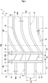
- FIG. 1 is a plan view of a tread portion 2 of a tire 1 showing one embodiment of the present invention.
- the present invention is used for an all-season pneumatic tire for a passenger car, and the car can run even on a snow road with such tires.
- the present invention may, for example, be used for a heavy-duty pneumatic tire, or a non-pneumatic tire the interior of which is not filled with pressurized air.
- the tread portion 2 has a designated mounting direction to a vehicle. Accordingly, as shown in FIG. 1 , the tire 1 has an outer tread end To located at an outer side of the vehicle and an inner tread end Ti located at an inner side of the vehicle, when the tire is mounted on the vehicle.
- the outer tread end To and the inner tread end Ti each correspond to the outermost ground contact position in a tire axial direction when 70% of a standardized load is applied to the tire 1 in a standardized state and the tire 1 is in contact with a plane at a camber angle of 0°.
- the "standardized state” is a state in which the tire 1 is fitted on a standardized rim (not shown) and inflated to a standardized internal pressure and no load is applied to the tire 1.
- the standardized state means a standard use state, corresponding to the purpose of use of the tire, where no load is applied to the tire.
- dimensions and the like of components of the tire 1 are values measured in the standardized state.
- the distance in the tire axial direction between the outer tread end To and the inner tread end Ti is a tread width TW.
- the "standardized rim” is a rim that is defined, in a standard system including a standard on which the tire 1 is based, by the standard for each tire, and is, for example, the "standard rim” in the JATMA standard, the "Design Rim” in the TRA standard, or the “Measuring Rim” in the ETRTO standard.
- the "standardized internal pressure” is an air pressure that is defined, in a standard system including a standard on which the tire 1 is based, by the standard for each tire, and is the “highest air pressure” in the JATMA standard, the maximum value indicated in the table "TIRE LOAD LIMITS AT VARIOUS COLD INFLATION PRESSURES" in the TRA standard, or the "INFLATION PRESSURE” in the ETRTO standard.
- the "standardized load” is a load that is defined, in a standard system including a standard on which the tire 1 is based, by the standard for each tire, and is the "maximum load capacity" in the JATMA standard, the maximum value indicated in the table "TIRE LOAD LIMITS AT VARIOUS COLD INFLATION PRESSURES" in the TRA standard, or the "LOAD CAPACITY” in the ETRTO standard.
- the "standardized load” refers to a load that acts on one tire in a standard mounting state of the tire.
- the "standard mounting state” refers to a state in which a tire is mounted on a standard vehicle corresponding to the purpose of use of the tire and the vehicle is stationary on a flat road surface in a state in which the vehicle can run.
- the tread portion 2 of the present embodiment includes a first circumferential groove 3 extending in a tire circumferential direction, an outer region 2A which is a region between the outer tread end To and the first circumferential groove 3, and an inner region 2B which is a region between the inner tread end Ti and the first circumferential groove 3.
- the outer region 2A has a plurality of outer lateral grooves 11 extending inward in the tire axial direction from the outer tread end To.
- the inner region 2B has a plurality of inner lateral grooves 12 extending inward in the tire axial direction from the inner tread end Ti.
- grooves such as the "lateral groove” and a circumferential groove described below each refer to a recess with a width not smaller than 1.5 mm obtained at the ground-contact surface, and are clearly distinguished from a sipe (not shown) with a width smaller than 1.5 mm in the form of a cutout.
- the plurality of outer lateral grooves 11 are formed such that a pitch length P1 thereof in the tire circumferential direction is larger than a pitch length P2 in the tire circumferential direction of the plurality of inner lateral grooves 12. Accordingly, in the inner region 2B, the number of the inner lateral grooves 12 is relatively large, and thus a high snow column shear force and an edge effect are exhibited and on-snow performance is improved. Meanwhile, in the outer region 2A, a length La in the tire circumferential direction of each of blocks B defined by the outer lateral grooves 11 is large, and thus steering stability is maintained.
- the pitch length P1 and the pitch length P2 are each a value (average pitch length) obtained by dividing a tire circumferential length at the outer tread end To or at the inner tread end Ti by the total number of the outer lateral grooves 11 or the total number of the inner lateral grooves 12.
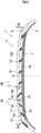
- FIG. 2 is a cross-sectional view taken along a line A-A in FIG. 1 .
- the plurality of outer lateral grooves 11 are each formed such that a groove depth Da thereof at the outer tread end To is smaller than a groove depth Db at the inner tread end Ti of each of the plurality of inner lateral grooves 12.
- a large snow column shear force is exhibited at the inner tread end Ti, and on-snow performance is further improved.
- the groove depth Da of the outer lateral groove 11 is relatively small at the outer tread end To, and thus steering stability is maintained.
- the groove depth Da is the shortest distance between a groove bottom 11s (the deepest portion) of the outer lateral groove 11 and the outer tread end To.
- the groove depth Db is the shortest distance between a groove bottom 12s (the deepest portion) of the inner lateral groove 12 and the inner tread end Ti.
- a ground-contact surface 2s of the outer region 2A is formed so as to have a rubber hardness Ra that is smaller than a rubber hardness Rb of a ground-contact surface 2i of the inner region 2B.
- the rubber hardness refers to a durometer A hardness which is measured at a standard temperature of 23°C ⁇ 2°C by a type A durometer, in accordance with JIS-K6253.
- the tire 1 includes tire components such as a carcass 6 extending between a pair of bead portions, which are not shown, and a belt layer 7 disposed adjacent to the outer side in the tire radial direction of the carcass 6 in the tread portion 2.
- tire components such as a carcass 6 extending between a pair of bead portions, which are not shown, and a belt layer 7 disposed adjacent to the outer side in the tire radial direction of the carcass 6 in the tread portion 2.
- a known mode is adopted as appropriate for these tire components.
- the tread portion 2 includes an outer tread rubber 15 forming the ground-contact surface 2s and an inner tread rubber 16 forming the ground-contact surface 2i.
- the outer tread rubber 15 and the inner tread rubber 16 are obtained by segmenting with a groove width center line 3c of the first circumferential groove 3.
- the outer tread rubber 15 is formed between the ground-contact surface 2s and the belt layer 7.
- the inner tread rubber 16 is formed between the ground-contact surface 2i and the belt layer 7.
- a range in which the outer tread rubber 15 and the inner tread rubber 16 are disposed is not limited to the illustrated range.
- the rubber hardness Ra of the ground-contact surface 2s of the outer region 2A is preferably not less than 0.70 times and more preferably not less than 0.75 times the rubber hardness Rb of the ground-contact surface 2i of the inner region 2B (rubber hardness of the inner tread rubber 16), and is preferably not more than 0.95 times and more preferably not more than 0.85 times the rubber hardness Rb of the ground-contact surface 2i of the inner region 2B (rubber hardness of the inner tread rubber 16).
- the rubber hardness Ra of the ground-contact surface 2s of the outer region 2A is not less than 0.70 times and not more than 0.95 times the rubber hardness Rb of the ground-contact surface 2i of the inner region 2B, the difference in stiffness between the outer region 2A and the inner region 2B is further reduced, and uneven wear resistance can be maintained even higher.
- the rubber hardness Ra of the ground-contact surface 2s of the outer region 2A is not particularly limited, but is preferably not smaller than 50 degrees and more preferably not smaller than 55 degrees, and is preferably not larger than 65 degrees and more preferably not larger than 60 degrees.
- An area A2 of the inner region 2B is preferably larger than an area A1 of the outer region 2A.
- the area A1 and the area A2 are each a virtual area obtained by filling the grooves (recesses each having a width not smaller than 1.5 mm at the ground-contact surface) excluding the first circumferential groove 3.
- the area A1 of the outer region 2A is preferably not less than 0.25 times and more preferably not less than 0.30 times the sum (A1+A2) of the area A1 of the outer region 2A and the area A2 of the inner region 2B, and is preferably not more than 0.50 times and more preferably not more than 0.45 times the sum (A1+A2) of the area A1 of the outer region 2A and the area A2 of the inner region 2B.
- the negative camber refers to a state in which a tire equator C is inclined toward the inner side from outer side in the axial direction of the vehicle upward from below when the tire 1 is mounted on the vehicle, and ground-contact pressure at the inner tread end Ti side is higher than that at the outer tread end To side.
- a camber angle at a negative camber is preferably not larger than 2°.
- the tread portion 2 has a second circumferential groove 4 located at the inner tread end Ti side with respect to the first circumferential groove 3.
- the first circumferential groove 3 and the second circumferential groove 4 for example, linearly extend parallel to the tire circumferential direction.
- Such a first circumferential groove 3 and such a second circumferential groove 4 can reduce change in stiffness in the tire circumferential direction between the outer region 2A and the inner region 2B, and occurrence of uneven wear can be effectively suppressed.
- the first circumferential groove 3 and the second circumferential groove 4 may extend in a zigzag or wavy manner with respect to the tire circumferential direction, for example.
- the outer lateral grooves 11 are connected to the first circumferential groove 3 of the present embodiment.
- the inner lateral grooves 12 are connected to the second circumferential groove 4 of the present embodiment.
- the outer region 2A of the present embodiment has a plurality of outer blocks 14 each defined by the outer lateral grooves 11 adjacent to the outer block 14 in the tire axial direction, the outer tread end To, and the first circumferential groove 3.
- the inner region 2B of the present embodiment has a plurality of inner blocks 15 each defined by the inner lateral grooves 12 adjacent to the inner block 15 in the tire circumferential direction, the inner tread end Ti, and the second circumferential groove 4.
- the second circumferential groove 4 is, for example, located at the outer tread end To side with respect to the tire equator C.
- the first circumferential groove 3 and the second circumferential groove 4 are located at the outer tread end To side with respect to the tire equator C in the present embodiment.
- the second circumferential groove 4 of the present embodiment is disposed in the inner region 2B.
- a separation distance L1 (hereinafter, referred to as first separation distance in some cases) in the tire axial direction between the groove width center line 3c of the first circumferential groove 3 and the outer tread end To is preferably not less than 15% and more preferably not less than 20% of the tread width TW, and is preferably not more than 35% and more preferably not more than 30% of the tread width TW. Since the first separation distance L1 is not less than 15% of the tread width TW, reduction in stiffness in the tire axial direction can be inhibited in the vicinity of the outer tread end To on which a larger lateral force acts during cornering. Since the first separation distance L1 is not more than 35% of the tread width TW, the area A2 of the inner region 2B can be ensured to be large.
- a separation distance L2 (hereinafter, referred to as second separation distance in some cases) in the tire axial direction between a groove width center line 4c of the second circumferential groove 4 and the tire equator C is formed so as to be smaller than the first separation distance L1. Accordingly, the length in the tire axial direction of each outer block 14, and the volume thereof are relatively large. Thus, the outer blocks 14 can serve sufficiently as support with respect to a large lateral force generated during cornering, so that steering stability is improved.
- the second separation distance L2 is not particularly limited, but is preferably not less than 2% and more preferably not less than 4% of the tread width TW, and is preferably not more than 12% and more preferably not more than 9% of the tread width TW.
- the second circumferential groove 4 is formed such that a groove depth D2 thereof is larger than a groove depth D1 of the first circumferential groove 3.
- a second circumferential groove 4 enables smooth draining of a layer of water between a road surface and the ground-contact surface 2i of the inner region 2B on which a relatively large ground-contact pressure acts, and thus wet performance can be increased.
- a relatively large ground-contact pressure occurs on the inner region 2B during straight running, thereby accelerating wear.
- the groove depth D2 of the second circumferential groove 4 is larger than the groove depth D1 of the first circumferential groove 3, the lives of the first circumferential groove 3 and the second circumferential groove 4 can be equalized and uneven wear can also be prevented.
- the groove depth D1 of the first circumferential groove 3 is preferably not less than 0.5 times and more preferably not less than 0.6 times the groove depth D2 of the second circumferential groove 4, and is more preferably not more than 0.9 times the groove depth D2 of the second circumferential groove 4.
- the groove depth D1 of the first circumferential groove 3 is preferably not less than 0.4 times and more preferably not less than 0.5 times the groove depth Da at the outer tread end To of each outer lateral groove 11, and is preferably not more than 0.9 times and more preferably not more than 0.8 times the groove depth Da at the outer tread of each outer lateral groove 11.
- the groove depth D1 of the first circumferential groove 3 is preferably 4 to 8 mm.
- the groove width W1 of the first circumferential groove 3 is, for example, substantially equal to the groove width W2 of the second circumferential groove 4.
- the groove width W1 of the first circumferential groove 3 is preferably not less than 10% and more preferably not less than 15% of the first separation distance L1, and is preferably not more than 30% and more preferably not more than 25% of the first separation distance L1.
- the "substantially equal” means that the groove width W1 of the first circumferential groove 3 is 80% to 125% of the groove width W2 of the second circumferential groove 4.
- the outer lateral grooves 11 extend parallel to the tire axial direction.
- the outer lateral grooves 11 may, for example, be inclined with respect to the tire axial direction.
- each of the plurality of outer lateral grooves 11 is connected to the first circumferential groove 3.
- Such outer lateral grooves 11 enable large snow columns to be formed in the outer region 2A.
- the outer lateral grooves 11 each extend from the outer tread end To to the first circumferential groove 3 with a uniform groove width Wa.
- the outer lateral grooves 11 are not limited to such a mode.
- the inner lateral grooves 12 each extend such that an angle ⁇ relative to the tire axial direction is increased continuously toward the second circumferential groove 4 from the inner tread end Ti side.
- each of the plurality of inner lateral grooves 12 is connected to the second circumferential groove 4.
- Such inner lateral grooves 12 enable large snow columns to be formed in the inner region 2B.
- the inner lateral grooves 12 each extend from the inner tread end Ti to the second circumferential groove 4 with a uniform groove width Wb.
- the inner lateral grooves 12 are not limited to such a mode.
- the groove width Wa of each outer lateral groove 11 is, for example, substantially equal to the groove width Wb of the inner lateral groove 12.
- the "substantially equal” means that the groove width Wa of the outer lateral groove 11 is 80% to 125% of the groove width Wb of the inner lateral groove 12.
- the groove width Wa of the outer lateral groove 11 is, for example, preferably not less than 50% and more preferably not less than 60% of the groove width W1 of the first circumferential groove 3, and is preferably not more than 80% and more preferably not more than 70% of the groove width W1 of the first circumferential groove 3.
- the groove depth Da at the outer tread end To of each of the plurality of outer lateral grooves 11 is preferably not less than 0.80 times and more preferably not less than 0.85 times the groove depth Db at the inner tread end Ti of each of the plurality of inner lateral grooves 12, and is preferably not more than 0.95 times and preferably not more than 0.90 times the groove depth Db at the inner tread end Ti of each of the plurality of inner lateral grooves 12. Since the groove depth Da of the outer lateral groove 11 is not less than 0.8 times and not more than 0.95 times the groove depth Db of the inner lateral groove 12, both on-snow performance and steering stability are further achieved.
- the groove depth Da at the outer tread end To of each of the plurality of outer lateral grooves 11 is not particularly limited, but is, for example, preferably not smaller than 2 mm and more preferably not smaller than 3 mm, and is preferably not larger than 7 mm and more preferably not larger than 6 mm.
- the pitch length P1 in the tire circumferential direction of the plurality of outer lateral grooves 11 is preferably not less than 1.10 times and more preferably not less than 1.15 times the pitch length P2 in the tire circumferential direction of the plurality of inner lateral grooves 12, and is preferably not more than 2.00 times and more preferably not more than 1.40 times the pitch length P2 in the tire circumferential direction of the plurality of inner lateral grooves 12. Since the pitch length P1 is not more than 2.00 times the pitch length P2, the number of the outer lateral grooves 11 is ensured, reduction in a snow column shear force or an edge effect can be inhibited in the outer region 2A, and the effect of improving on-snow performance is highly maintained.
- the pitch length P1 is not particularly limited, but is preferably not less than 10% and more preferably not less than 14% of the tread width TW, and is preferably not more than 26% and more preferably not more than 22% of the tread width TW.
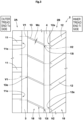
- FIG. 3 is a plan view of a portion, of the tread portion 2, around the first circumferential groove 3 and the second circumferential groove 4.
- the inner region 2B is divided into a middle land portion 18 between the second circumferential groove 4 and the first circumferential groove 3 and an inner shoulder land portion 19 between the second circumferential groove 4 and the inner tread end Ti.
- the middle land portion 18, for example, has a plurality of middle lateral grooves 13 connecting the first circumferential groove 3 and the second circumferential groove 4.
- the middle lateral grooves 13 linearly extend so as to be inclined with respect to the tire axial direction.
- a pitch length of the middle lateral grooves 13 is, for example, equal to the pitch length P2 of the inner lateral grooves 12 (shown in FIG. 1 ).
- each of the middle lateral grooves 13 does not communicate with any of the outer lateral grooves 11 via the first circumferential groove 3.
- the stiffness of a portion around the first circumferential groove 3 is inhibited from locally decreasing, change in stiffness across the boundary between the outer region 2A and the inner region 2B having rubber hardnesses different from each other can be reduced, and thus occurrence of uneven wear can be suppressed.
- the "does not communicate via the first circumferential groove 3" means that a virtual straight line V1 which is parallel to the tire axial direction and is located at an open end 13e, of the middle lateral groove 13, open at the first circumferential groove 3 is shifted in the tire circumferential direction with respect to an open end 1 1e, of the outer lateral groove 11, open at the first circumferential groove 3.
- each of the middle lateral grooves 13 communicates with any of the inner lateral grooves 12 via the second circumferential groove 4.
- the stiffness of a portion near an open end 12e, of each inner lateral groove 12, open at the second circumferential groove 4 decreases, deformation of the tread portion 2 is increased at such a portion, and thus snow that is packed in the inner lateral groove 12 having a relatively large length in the tire axial direction can be smoothly removed around an opening end 12e. Therefore, on-snow performance can be improved.
- the "communicate via the second circumferential groove 4" means that a virtual straight line V2 which is parallel to the tire axial direction and is located at an opening end 13i, of the middle lateral groove 13, open at the second circumferential groove 4 overlaps, in the tire circumferential direction, the opening end 12e, of the inner lateral groove 12, open at the second circumferential groove 4.
- a groove width Wc of each middle lateral groove 13 is not particularly limited, but is preferably not less than 30% and more preferably not less than 40% of the groove width Wb of the inner lateral groove 12 (shown in FIG. 2 ), and is preferably not more than 70% and more preferably not more than 60% of the groove width Wb of the inner lateral groove 12 (shown in FIG. 2 ).
- the outer region 2A and the inner region 2B may have a plurality of sipes (not shown) extending parallel to the outer lateral groove 11, the inner lateral groove 12, and/or the middle lateral groove 13.
- the present invention includes the following aspects.
- a tire including a tread portion, wherein
- each of the plurality of outer lateral grooves is connected to the first circumferential groove.
- each of the plurality of inner lateral grooves is connected to the second circumferential groove.
Landscapes
- Engineering & Computer Science (AREA)
- Mechanical Engineering (AREA)
- Tires In General (AREA)
Abstract
Description
- The present invention relates to a tire.
-
Japanese Laid-Open Patent Publication No. 2020-100220 - However, a problem arises that uneven wear in which wear concentrates on the inner shoulder land portion as compared to the outer shoulder land portion of the tread portion is caused in the tire described above.
- The present invention has been made in view of the above circumstances, and a main object of the present invention is to provide a tire capable of improving on-snow performance while maintaining uneven wear resistance and steering stability.
- The present invention is directed to a tire including a tread portion, wherein the tread portion has a designated mounting direction to a vehicle, the tread portion includes: an outer tread end located at an outer side of the vehicle when the tire is mounted on the vehicle; an inner tread end located at an inner side of the vehicle when the tire is mounted on the vehicle; a first circumferential groove extending in a tire circumferential direction; an outer region which is a region between the outer tread end and the first circumferential groove; and an inner region which is a region between the inner tread end and the first circumferential groove, a rubber hardness of a ground-contact surface of the outer region is smaller than a rubber hardness of a ground-contact surface of the inner region, the outer region has a plurality of outer lateral grooves extending inward in a tire axial direction from the outer tread end, the inner region has a plurality of inner lateral grooves extending inward in the tire axial direction from the inner tread end, a one-pitch length in the tire circumferential direction of the plurality of outer lateral grooves is larger than a one-pitch length in the tire circumferential direction of the plurality of inner lateral grooves, and a groove depth at the outer tread end of each of the plurality of outer lateral grooves is smaller than a groove depth at the inner tread end of each of the plurality of inner lateral grooves.
- As a result of employing the above configuration, the tire according to the present invention can improve on-snow performance while maintaining uneven wear resistance and steering stability.
-
-
FIG. 1 is a plan view of a tread portion showing one embodiment of a tire according to the present invention; -
FIG. 2 is a cross-sectional view of the tire inFIG. 1 taken along a line A-A; and -
FIG. 3 is an enlarged plan view of the tread portion. - Hereinafter, one embodiment of the present invention will be described with reference to the drawings. The drawings contain exaggerated expressions and expressions that differ from the dimensional ratio of the actual structure in order to help the understanding of the present invention. In addition, when there are a plurality of embodiments, the same or common elements are denoted by the same reference characters throughout the description, and the redundant description thereof is omitted.
-
FIG. 1 is a plan view of atread portion 2 of a tire 1 showing one embodiment of the present invention. The present invention is used for an all-season pneumatic tire for a passenger car, and the car can run even on a snow road with such tires. However, the present invention may, for example, be used for a heavy-duty pneumatic tire, or a non-pneumatic tire the interior of which is not filled with pressurized air. - The
tread portion 2 has a designated mounting direction to a vehicle. Accordingly, as shown inFIG. 1 , the tire 1 has an outer tread end To located at an outer side of the vehicle and an inner tread end Ti located at an inner side of the vehicle, when the tire is mounted on the vehicle. - In the case of a pneumatic tire, the outer tread end To and the inner tread end Ti each correspond to the outermost ground contact position in a tire axial direction when 70% of a standardized load is applied to the tire 1 in a standardized state and the tire 1 is in contact with a plane at a camber angle of 0°. In the case of the pneumatic tire 1 for which various standards are defined, the "standardized state" is a state in which the tire 1 is fitted on a standardized rim (not shown) and inflated to a standardized internal pressure and no load is applied to the tire 1. In the case of a non-pneumatic tire or a tire for which various standards are not defined, the standardized state means a standard use state, corresponding to the purpose of use of the tire, where no load is applied to the tire. In the present description, unless otherwise specified, dimensions and the like of components of the tire 1 are values measured in the standardized state. In addition, the distance in the tire axial direction between the outer tread end To and the inner tread end Ti is a tread width TW.
- The "standardized rim" is a rim that is defined, in a standard system including a standard on which the tire 1 is based, by the standard for each tire, and is, for example, the "standard rim" in the JATMA standard, the "Design Rim" in the TRA standard, or the "Measuring Rim" in the ETRTO standard.
- The "standardized internal pressure" is an air pressure that is defined, in a standard system including a standard on which the tire 1 is based, by the standard for each tire, and is the "highest air pressure" in the JATMA standard, the maximum value indicated in the table "TIRE LOAD LIMITS AT VARIOUS COLD INFLATION PRESSURES" in the TRA standard, or the "INFLATION PRESSURE" in the ETRTO standard.
- The "standardized load" is a load that is defined, in a standard system including a standard on which the tire 1 is based, by the standard for each tire, and is the "maximum load capacity" in the JATMA standard, the maximum value indicated in the table "TIRE LOAD LIMITS AT VARIOUS COLD INFLATION PRESSURES" in the TRA standard, or the "LOAD CAPACITY" in the ETRTO standard. In the case of a non-pneumatic tire or a tire for which various standards are not defined, the "standardized load" refers to a load that acts on one tire in a standard mounting state of the tire. The "standard mounting state" refers to a state in which a tire is mounted on a standard vehicle corresponding to the purpose of use of the tire and the vehicle is stationary on a flat road surface in a state in which the vehicle can run.
- The
tread portion 2 of the present embodiment includes a firstcircumferential groove 3 extending in a tire circumferential direction, anouter region 2A which is a region between the outer tread end To and the firstcircumferential groove 3, and aninner region 2B which is a region between the inner tread end Ti and the firstcircumferential groove 3. - The
outer region 2A has a plurality of outerlateral grooves 11 extending inward in the tire axial direction from the outer tread end To. Theinner region 2B has a plurality of innerlateral grooves 12 extending inward in the tire axial direction from the inner tread end Ti. In the present description, grooves such as the "lateral groove" and a circumferential groove described below each refer to a recess with a width not smaller than 1.5 mm obtained at the ground-contact surface, and are clearly distinguished from a sipe (not shown) with a width smaller than 1.5 mm in the form of a cutout. - The plurality of outer
lateral grooves 11 are formed such that a pitch length P1 thereof in the tire circumferential direction is larger than a pitch length P2 in the tire circumferential direction of the plurality of innerlateral grooves 12. Accordingly, in theinner region 2B, the number of the innerlateral grooves 12 is relatively large, and thus a high snow column shear force and an edge effect are exhibited and on-snow performance is improved. Meanwhile, in theouter region 2A, a length La in the tire circumferential direction of each of blocks B defined by the outerlateral grooves 11 is large, and thus steering stability is maintained. For example, for the tire 1, a so-called variable pitch method in which a plurality of pitch elements having pitch lengths different from each other in the tire circumferential direction are randomly arranged in the tire circumferential direction is used in some cases. In this case, the pitch length P1 and the pitch length P2 are each a value (average pitch length) obtained by dividing a tire circumferential length at the outer tread end To or at the inner tread end Ti by the total number of the outerlateral grooves 11 or the total number of the innerlateral grooves 12. -
FIG. 2 is a cross-sectional view taken along a line A-A inFIG. 1 . As shown inFIG. 2 , the plurality of outerlateral grooves 11 are each formed such that a groove depth Da thereof at the outer tread end To is smaller than a groove depth Db at the inner tread end Ti of each of the plurality of innerlateral grooves 12. Thus, a large snow column shear force is exhibited at the inner tread end Ti, and on-snow performance is further improved. Meanwhile, the groove depth Da of the outerlateral groove 11 is relatively small at the outer tread end To, and thus steering stability is maintained. The groove depth Da is the shortest distance between agroove bottom 11s (the deepest portion) of the outerlateral groove 11 and the outer tread end To. The groove depth Db is the shortest distance between agroove bottom 12s (the deepest portion) of the innerlateral groove 12 and the inner tread end Ti. - A ground-
contact surface 2s of theouter region 2A is formed so as to have a rubber hardness Ra that is smaller than a rubber hardness Rb of a ground-contact surface 2i of theinner region 2B. Thus, the difference in stiffness between theouter region 2A and theinner region 2B is reduced, so that uneven wear such as early wear of theinner region 2B is inhibited. Therefore, the tire 1 of the present invention can improve on-snow performance while maintaining uneven wear resistance and steering stability. In the present description, the rubber hardness refers to a durometer A hardness which is measured at a standard temperature of 23°C±2°C by a type A durometer, in accordance with JIS-K6253. - The tire 1 includes tire components such as a
carcass 6 extending between a pair of bead portions, which are not shown, and a belt layer 7 disposed adjacent to the outer side in the tire radial direction of thecarcass 6 in thetread portion 2. A known mode is adopted as appropriate for these tire components. - The
tread portion 2 includes anouter tread rubber 15 forming the ground-contact surface 2s and aninner tread rubber 16 forming the ground-contact surface 2i. Theouter tread rubber 15 and theinner tread rubber 16 are obtained by segmenting with a groovewidth center line 3c of the firstcircumferential groove 3. Theouter tread rubber 15 is formed between the ground-contact surface 2s and the belt layer 7. Theinner tread rubber 16 is formed between the ground-contact surface 2i and the belt layer 7. A range in which theouter tread rubber 15 and theinner tread rubber 16 are disposed is not limited to the illustrated range. - The rubber hardness Ra of the ground-
contact surface 2s of theouter region 2A (rubber hardness of the outer tread rubber 15) is preferably not less than 0.70 times and more preferably not less than 0.75 times the rubber hardness Rb of the ground-contact surface 2i of theinner region 2B (rubber hardness of the inner tread rubber 16), and is preferably not more than 0.95 times and more preferably not more than 0.85 times the rubber hardness Rb of the ground-contact surface 2i of theinner region 2B (rubber hardness of the inner tread rubber 16). Since the rubber hardness Ra of the ground-contact surface 2s of theouter region 2A is not less than 0.70 times and not more than 0.95 times the rubber hardness Rb of the ground-contact surface 2i of theinner region 2B, the difference in stiffness between theouter region 2A and theinner region 2B is further reduced, and uneven wear resistance can be maintained even higher. - The rubber hardness Ra of the ground-
contact surface 2s of theouter region 2A is not particularly limited, but is preferably not smaller than 50 degrees and more preferably not smaller than 55 degrees, and is preferably not larger than 65 degrees and more preferably not larger than 60 degrees. - An area A2 of the
inner region 2B is preferably larger than an area A1 of theouter region 2A. Thus, when the tire 1 is mounted at a negative camber, the ground-contact area of theinner region 2B having a relatively large number of the lateral grooves is larger, and thus on-snow performance can be further improved. The area A1 and the area A2 are each a virtual area obtained by filling the grooves (recesses each having a width not smaller than 1.5 mm at the ground-contact surface) excluding the firstcircumferential groove 3. From the viewpoint of achieving both on-snow performance and steering stability, the area A1 of theouter region 2A is preferably not less than 0.25 times and more preferably not less than 0.30 times the sum (A1+A2) of the area A1 of theouter region 2A and the area A2 of theinner region 2B, and is preferably not more than 0.50 times and more preferably not more than 0.45 times the sum (A1+A2) of the area A1 of theouter region 2A and the area A2 of theinner region 2B. The negative camber refers to a state in which a tire equator C is inclined toward the inner side from outer side in the axial direction of the vehicle upward from below when the tire 1 is mounted on the vehicle, and ground-contact pressure at the inner tread end Ti side is higher than that at the outer tread end To side. A camber angle at a negative camber is preferably not larger than 2°. - As shown in
FIG. 1 andFIG. 2 , thetread portion 2 has a secondcircumferential groove 4 located at the inner tread end Ti side with respect to the firstcircumferential groove 3. The firstcircumferential groove 3 and the secondcircumferential groove 4, for example, linearly extend parallel to the tire circumferential direction. Such a firstcircumferential groove 3 and such a secondcircumferential groove 4 can reduce change in stiffness in the tire circumferential direction between theouter region 2A and theinner region 2B, and occurrence of uneven wear can be effectively suppressed. The firstcircumferential groove 3 and the secondcircumferential groove 4 may extend in a zigzag or wavy manner with respect to the tire circumferential direction, for example. - The outer
lateral grooves 11 are connected to the firstcircumferential groove 3 of the present embodiment. The innerlateral grooves 12 are connected to the secondcircumferential groove 4 of the present embodiment. Theouter region 2A of the present embodiment has a plurality ofouter blocks 14 each defined by the outerlateral grooves 11 adjacent to theouter block 14 in the tire axial direction, the outer tread end To, and the firstcircumferential groove 3. Theinner region 2B of the present embodiment has a plurality ofinner blocks 15 each defined by the innerlateral grooves 12 adjacent to theinner block 15 in the tire circumferential direction, the inner tread end Ti, and the secondcircumferential groove 4. - The second
circumferential groove 4 is, for example, located at the outer tread end To side with respect to the tire equator C. In other words, the firstcircumferential groove 3 and the secondcircumferential groove 4 are located at the outer tread end To side with respect to the tire equator C in the present embodiment. The secondcircumferential groove 4 of the present embodiment is disposed in theinner region 2B. - A separation distance L1 (hereinafter, referred to as first separation distance in some cases) in the tire axial direction between the groove
width center line 3c of the firstcircumferential groove 3 and the outer tread end To is preferably not less than 15% and more preferably not less than 20% of the tread width TW, and is preferably not more than 35% and more preferably not more than 30% of the tread width TW. Since the first separation distance L1 is not less than 15% of the tread width TW, reduction in stiffness in the tire axial direction can be inhibited in the vicinity of the outer tread end To on which a larger lateral force acts during cornering. Since the first separation distance L1 is not more than 35% of the tread width TW, the area A2 of theinner region 2B can be ensured to be large. - A separation distance L2 (hereinafter, referred to as second separation distance in some cases) in the tire axial direction between a groove
width center line 4c of the secondcircumferential groove 4 and the tire equator C is formed so as to be smaller than the first separation distance L1. Accordingly, the length in the tire axial direction of eachouter block 14, and the volume thereof are relatively large. Thus, theouter blocks 14 can serve sufficiently as support with respect to a large lateral force generated during cornering, so that steering stability is improved. The second separation distance L2 is not particularly limited, but is preferably not less than 2% and more preferably not less than 4% of the tread width TW, and is preferably not more than 12% and more preferably not more than 9% of the tread width TW. - The second
circumferential groove 4 is formed such that a groove depth D2 thereof is larger than a groove depth D1 of the firstcircumferential groove 3. When the tire 1 is mounted at a negative camber, such a secondcircumferential groove 4 enables smooth draining of a layer of water between a road surface and the ground-contact surface 2i of theinner region 2B on which a relatively large ground-contact pressure acts, and thus wet performance can be increased. In addition, when the tire 1 is mounted at a negative camber, a relatively large ground-contact pressure occurs on theinner region 2B during straight running, thereby accelerating wear. However, since the groove depth D2 of the secondcircumferential groove 4 is larger than the groove depth D1 of the firstcircumferential groove 3, the lives of the firstcircumferential groove 3 and the secondcircumferential groove 4 can be equalized and uneven wear can also be prevented. - In order to effectively exhibit such an effect, the groove depth D1 of the first
circumferential groove 3 is preferably not less than 0.5 times and more preferably not less than 0.6 times the groove depth D2 of the secondcircumferential groove 4, and is more preferably not more than 0.9 times the groove depth D2 of the secondcircumferential groove 4. In addition, the groove depth D1 of the firstcircumferential groove 3 is preferably not less than 0.4 times and more preferably not less than 0.5 times the groove depth Da at the outer tread end To of each outerlateral groove 11, and is preferably not more than 0.9 times and more preferably not more than 0.8 times the groove depth Da at the outer tread of each outerlateral groove 11. The groove depth D1 of the firstcircumferential groove 3 is preferably 4 to 8 mm. - The groove width W1 of the first
circumferential groove 3 is, for example, substantially equal to the groove width W2 of the secondcircumferential groove 4. The groove width W1 of the firstcircumferential groove 3 is preferably not less than 10% and more preferably not less than 15% of the first separation distance L1, and is preferably not more than 30% and more preferably not more than 25% of the first separation distance L1. In the present description, the "substantially equal" means that the groove width W1 of the firstcircumferential groove 3 is 80% to 125% of the groove width W2 of the secondcircumferential groove 4. - The outer
lateral grooves 11, for example, linearly extend. In the present embodiment, the outerlateral grooves 11 extend parallel to the tire axial direction. The outerlateral grooves 11 may, for example, be inclined with respect to the tire axial direction. In the present embodiment, each of the plurality of outerlateral grooves 11 is connected to the firstcircumferential groove 3. Such outerlateral grooves 11 enable large snow columns to be formed in theouter region 2A. The outerlateral grooves 11 each extend from the outer tread end To to the firstcircumferential groove 3 with a uniform groove width Wa. The outerlateral grooves 11 are not limited to such a mode. - The inner
lateral grooves 12, for example, each extend so as to form an arc shape that is convex to one side (upward inFIG. 1 ) in the tire circumferential direction. In the present embodiment, the innerlateral grooves 12 each extend such that an angle α relative to the tire axial direction is increased continuously toward the secondcircumferential groove 4 from the inner tread end Ti side. In the present embodiment, each of the plurality of innerlateral grooves 12 is connected to the secondcircumferential groove 4. Such innerlateral grooves 12 enable large snow columns to be formed in theinner region 2B. The innerlateral grooves 12 each extend from the inner tread end Ti to the secondcircumferential groove 4 with a uniform groove width Wb. The innerlateral grooves 12 are not limited to such a mode. - The groove width Wa of each outer
lateral groove 11 is, for example, substantially equal to the groove width Wb of the innerlateral groove 12. Thus, the difference in stiffness between theouter region 2A and theinner region 2B can be effectively reduced. In the present description, the "substantially equal" means that the groove width Wa of the outerlateral groove 11 is 80% to 125% of the groove width Wb of the innerlateral groove 12. The groove width Wa of the outerlateral groove 11 is, for example, preferably not less than 50% and more preferably not less than 60% of the groove width W1 of the firstcircumferential groove 3, and is preferably not more than 80% and more preferably not more than 70% of the groove width W1 of the firstcircumferential groove 3. - The groove depth Da at the outer tread end To of each of the plurality of outer
lateral grooves 11 is preferably not less than 0.80 times and more preferably not less than 0.85 times the groove depth Db at the inner tread end Ti of each of the plurality of innerlateral grooves 12, and is preferably not more than 0.95 times and preferably not more than 0.90 times the groove depth Db at the inner tread end Ti of each of the plurality of innerlateral grooves 12. Since the groove depth Da of the outerlateral groove 11 is not less than 0.8 times and not more than 0.95 times the groove depth Db of the innerlateral groove 12, both on-snow performance and steering stability are further achieved. The groove depth Da at the outer tread end To of each of the plurality of outerlateral grooves 11 is not particularly limited, but is, for example, preferably not smaller than 2 mm and more preferably not smaller than 3 mm, and is preferably not larger than 7 mm and more preferably not larger than 6 mm. - In addition, the pitch length P1 in the tire circumferential direction of the plurality of outer
lateral grooves 11 is preferably not less than 1.10 times and more preferably not less than 1.15 times the pitch length P2 in the tire circumferential direction of the plurality of innerlateral grooves 12, and is preferably not more than 2.00 times and more preferably not more than 1.40 times the pitch length P2 in the tire circumferential direction of the plurality of innerlateral grooves 12. Since the pitch length P1 is not more than 2.00 times the pitch length P2, the number of the outerlateral grooves 11 is ensured, reduction in a snow column shear force or an edge effect can be inhibited in theouter region 2A, and the effect of improving on-snow performance is highly maintained. In addition, an excessive reduction in the stiffness of theinner region 2B is inhibited. Since the pitch length P1 is not less than 1.10 times the pitch length P2, a larger snow column shear force and a higher edge effect in theinner region 2B can be exhibited. The pitch length P1 is not particularly limited, but is preferably not less than 10% and more preferably not less than 14% of the tread width TW, and is preferably not more than 26% and more preferably not more than 22% of the tread width TW. -
FIG. 3 is a plan view of a portion, of thetread portion 2, around the firstcircumferential groove 3 and the secondcircumferential groove 4. As shown inFIG. 3 , theinner region 2B is divided into amiddle land portion 18 between the secondcircumferential groove 4 and the firstcircumferential groove 3 and an innershoulder land portion 19 between the secondcircumferential groove 4 and the inner tread end Ti. - The
middle land portion 18, for example, has a plurality of middlelateral grooves 13 connecting the firstcircumferential groove 3 and the secondcircumferential groove 4. In the present embodiment, the middlelateral grooves 13 linearly extend so as to be inclined with respect to the tire axial direction. A pitch length of the middlelateral grooves 13 is, for example, equal to the pitch length P2 of the inner lateral grooves 12 (shown inFIG. 1 ). - In the present embodiment, each of the middle
lateral grooves 13 does not communicate with any of the outerlateral grooves 11 via the firstcircumferential groove 3. Thus, the stiffness of a portion around the firstcircumferential groove 3 is inhibited from locally decreasing, change in stiffness across the boundary between theouter region 2A and theinner region 2B having rubber hardnesses different from each other can be reduced, and thus occurrence of uneven wear can be suppressed. The "does not communicate via the firstcircumferential groove 3" means that a virtual straight line V1 which is parallel to the tire axial direction and is located at anopen end 13e, of the middlelateral groove 13, open at the firstcircumferential groove 3 is shifted in the tire circumferential direction with respect to an open end 1 1e, of the outerlateral groove 11, open at the firstcircumferential groove 3. - In the present embodiment, each of the middle
lateral grooves 13 communicates with any of the innerlateral grooves 12 via the secondcircumferential groove 4. Thus, the stiffness of a portion near anopen end 12e, of each innerlateral groove 12, open at the secondcircumferential groove 4 decreases, deformation of thetread portion 2 is increased at such a portion, and thus snow that is packed in the innerlateral groove 12 having a relatively large length in the tire axial direction can be smoothly removed around an openingend 12e. Therefore, on-snow performance can be improved. The "communicate via the secondcircumferential groove 4" means that a virtual straight line V2 which is parallel to the tire axial direction and is located at an openingend 13i, of the middlelateral groove 13, open at the secondcircumferential groove 4 overlaps, in the tire circumferential direction, the openingend 12e, of the innerlateral groove 12, open at the secondcircumferential groove 4. - A groove width Wc of each middle
lateral groove 13 is not particularly limited, but is preferably not less than 30% and more preferably not less than 40% of the groove width Wb of the inner lateral groove 12 (shown inFIG. 2 ), and is preferably not more than 70% and more preferably not more than 60% of the groove width Wb of the inner lateral groove 12 (shown inFIG. 2 ). - Although one embodiment of the present invention has been described in detail above, the present invention is not limited to the above specific embodiment, and various modifications can be made to implement the present invention. For example, the
outer region 2A and theinner region 2B may have a plurality of sipes (not shown) extending parallel to the outerlateral groove 11, the innerlateral groove 12, and/or the middlelateral groove 13. - The present invention includes the following aspects.
- A tire including a tread portion, wherein
- the tread portion has a designated mounting direction to a vehicle,
- the tread portion includes:
- an outer tread end located at an outer side of the vehicle when the tire is mounted on the vehicle;
- an inner tread end located at an inner side of the vehicle when the tire is mounted on the vehicle;
- a first circumferential groove extending in a tire circumferential direction;
- an outer region which is a region between the outer tread end and the first circumferential groove; and
- an inner region which is a region between the inner tread end and the first circumferential groove,
- a rubber hardness of a ground-contact surface of the outer region is smaller than a rubber hardness of a ground-contact surface of the inner region,
- the outer region has a plurality of outer lateral grooves extending inward in a tire axial direction from the outer tread end,
- the inner region has a plurality of inner lateral grooves extending inward in the tire axial direction from the inner tread end,
- a pitch length in the tire circumferential direction of the plurality of outer lateral grooves is larger than a pitch length in the tire circumferential direction of the plurality of inner lateral grooves, and
- a groove depth at the outer tread end of each of the plurality of outer lateral grooves is smaller than a groove depth at the inner tread end of each of the plurality of inner lateral grooves.
- The tire according to Present Invention 1, wherein the groove depth at the outer tread end of each of the plurality of outer lateral grooves is not less than 0.8 times the groove depth at the inner tread end of each of the plurality of inner lateral grooves.
- The tire according to
Present Invention 1 or 2, wherein the pitch length in the tire circumferential direction of the plurality of outer lateral grooves is 1.1 to 2.0 times the pitch length in the tire circumferential direction of the plurality of inner lateral grooves. - The tire according to any one of Present Inventions 1 to 3, wherein the rubber hardness of the ground-contact surface of the outer region is 0.70 to 0.95 times the rubber hardness of the ground-contact surface of the inner region.
- The tire according to any one of Present Inventions 1 to 4, wherein
- the tread portion has a second circumferential groove located at the inner tread end side with respect to the first circumferential groove, and
- a groove depth of the second circumferential groove is larger than a groove depth of the first circumferential groove.
- The tire according to Present Invention 5, wherein the groove depth of the first circumferential groove is larger than 0.5 times the groove depth of the second circumferential groove.
- The tire according to any one of Present Inventions 1 to 6, wherein an area of the outer region is 0.25 to 0.5 times the sum of the area of the outer region and an area of the inner region.
- The tire according to any one of Present Inventions 1 to 7, wherein each of the plurality of outer lateral grooves is connected to the first circumferential groove.
- The tire according to
Present Invention 5 or 6, wherein each of the plurality of inner lateral grooves is connected to the second circumferential groove.
Claims (9)
- A tire (1) including a tread portion (2), whereinthe tread portion (2) has a designated mounting direction to a vehicle,the tread portion (2) includes:an outer tread end (To) located at an outer side of the vehicle when the tire (1) is mounted on the vehicle;an inner tread end (Ti) located at an inner side of the vehicle when the tire (1) is mounted on the vehicle;a first circumferential groove (3) extending in a tire circumferential direction;an outer region (2A) which is a region between the outer tread end (To) and the first circumferential groove (3); andan inner region (2B) which is a region between the inner tread end (Ti) and the first circumferential groove (3),a rubber hardness (Ra) of a ground-contact surface (2s) of the outer region (2A) is smaller than a rubber hardness (Rb) of a ground-contact surface (2i) of the inner region (2B),the outer region (2A) has a plurality of outer lateral grooves (11) extending inward in a tire axial direction from the outer tread end (To),the inner region (2B) has a plurality of inner lateral grooves (12) extending inward in the tire axial direction from the inner tread end (Ti),a pitch length (P1) in the tire circumferential direction of the plurality of outer lateral grooves (11) is larger than a pitch length (P2) in the tire circumferential direction of the plurality of inner lateral grooves (12), anda groove depth (Da) at the outer tread end (To) of each of the plurality of outer lateral grooves (11) is smaller than a groove depth (Db) at the inner tread end (Ti) of each of the plurality of inner lateral grooves (12).
- The tire (1) according to claim 1, wherein the groove depth (Da) at the outer tread end (To) of each of the plurality of outer lateral grooves (11) is not less than 0.8 times the groove depth (Db) at the inner tread end (Ti) of each of the plurality of inner lateral grooves (12).
- The tire (1) according to claim 1 or 2, wherein the pitch length (P1) in the tire circumferential direction of the plurality of outer lateral grooves (11) is 1.1 to 2.0 times the pitch length (P2) in the tire circumferential direction of the plurality of inner lateral grooves (12).
- The tire (1) according to any one of claims 1 to 3, wherein the rubber hardness (Ra) of the ground-contact surface (2s) of the outer region (2A) is 0.70 to 0.95 times the rubber hardness (Rb) of the ground-contact surface (2i) of the inner region (2B).
- The tire (1) according to any one of claims 1 to 4, whereinthe tread portion (2) has a second circumferential groove (4) located at the inner tread end (Ti) side with respect to the first circumferential groove (3), anda groove depth (D2) of the second circumferential groove (4) is larger than a groove depth (D1) of the first circumferential groove (3).
- The tire (1) according to claim 5, wherein the groove depth (D1) of the first circumferential groove (3) is larger than 0.5 times the groove depth (D2) of the second circumferential groove (4).
- The tire (1) according to any one of claims 1 to 6, wherein an area (A1) of the outer region (2A) is 0.25 to 0.5 times the sum of the area (A1) of the outer region (2A) and an area (A2) of the inner region (2B).
- The tire (1) according to any one of claims 1 to 7, wherein each of the plurality of outer lateral grooves (11) is connected to the first circumferential groove (3).
- The tire (1) according to claim 5 or 6, wherein each of the plurality of inner lateral grooves (12) is connected to the second circumferential groove (4).
Applications Claiming Priority (1)
| Application Number | Priority Date | Filing Date | Title |
|---|---|---|---|
| JP2023100199A JP2025000378A (en) | 2023-06-19 | 2023-06-19 | tire |
Publications (2)
| Publication Number | Publication Date |
|---|---|
| EP4480717A1 true EP4480717A1 (en) | 2024-12-25 |
| EP4480717B1 EP4480717B1 (en) | 2025-12-03 |
Family
ID=91129444
Family Applications (1)
| Application Number | Title | Priority Date | Filing Date |
|---|---|---|---|
| EP24176307.7A Active EP4480717B1 (en) | 2023-06-19 | 2024-05-16 | Tire |
Country Status (2)
| Country | Link |
|---|---|
| EP (1) | EP4480717B1 (en) |
| JP (1) | JP2025000378A (en) |
Citations (9)
| Publication number | Priority date | Publication date | Assignee | Title |
|---|---|---|---|---|
| JPH11321237A (en) * | 1998-05-07 | 1999-11-24 | Toyo Tire & Rubber Co Ltd | Pneumatic radial tire |
| EP1140527A1 (en) * | 1998-12-21 | 2001-10-10 | PIRELLI PNEUMATICI S.p.A. | Dual composition tread band for tire |
| EP1619048A1 (en) * | 2004-07-15 | 2006-01-25 | Continental Aktiengesellschaft | Pneumatic vehicle tire |
| EP2113399A1 (en) * | 2008-04-28 | 2009-11-04 | The Yokohama Rubber Co., Ltd. | Pneumatic tire |
| US20110048600A1 (en) * | 2009-05-29 | 2011-03-03 | Toyo Tire & Rubber Co. Ltd. | Pneumatic Tire |
| US20140373990A1 (en) * | 2012-02-15 | 2014-12-25 | Toyo Tire & Rubber Co., Ltd. | Pneumatic tire |
| US20160152084A1 (en) * | 2013-07-23 | 2016-06-02 | The Yokohama Rubber Co., Ltd. | Pneumatic Tire |
| JP2020100220A (en) | 2018-12-20 | 2020-07-02 | 住友ゴム工業株式会社 | tire |
| EP4190587A1 (en) * | 2021-12-02 | 2023-06-07 | Sumitomo Rubber Industries, Ltd. | Tire |
-
2023
- 2023-06-19 JP JP2023100199A patent/JP2025000378A/en active Pending
-
2024
- 2024-05-16 EP EP24176307.7A patent/EP4480717B1/en active Active
Patent Citations (9)
| Publication number | Priority date | Publication date | Assignee | Title |
|---|---|---|---|---|
| JPH11321237A (en) * | 1998-05-07 | 1999-11-24 | Toyo Tire & Rubber Co Ltd | Pneumatic radial tire |
| EP1140527A1 (en) * | 1998-12-21 | 2001-10-10 | PIRELLI PNEUMATICI S.p.A. | Dual composition tread band for tire |
| EP1619048A1 (en) * | 2004-07-15 | 2006-01-25 | Continental Aktiengesellschaft | Pneumatic vehicle tire |
| EP2113399A1 (en) * | 2008-04-28 | 2009-11-04 | The Yokohama Rubber Co., Ltd. | Pneumatic tire |
| US20110048600A1 (en) * | 2009-05-29 | 2011-03-03 | Toyo Tire & Rubber Co. Ltd. | Pneumatic Tire |
| US20140373990A1 (en) * | 2012-02-15 | 2014-12-25 | Toyo Tire & Rubber Co., Ltd. | Pneumatic tire |
| US20160152084A1 (en) * | 2013-07-23 | 2016-06-02 | The Yokohama Rubber Co., Ltd. | Pneumatic Tire |
| JP2020100220A (en) | 2018-12-20 | 2020-07-02 | 住友ゴム工業株式会社 | tire |
| EP4190587A1 (en) * | 2021-12-02 | 2023-06-07 | Sumitomo Rubber Industries, Ltd. | Tire |
Also Published As
| Publication number | Publication date |
|---|---|
| EP4480717B1 (en) | 2025-12-03 |
| JP2025000378A (en) | 2025-01-07 |
Similar Documents
| Publication | Publication Date | Title |
|---|---|---|
| EP3178668B1 (en) | Pneumatic tire | |
| EP2578418B1 (en) | Pneumatic tire | |
| EP3388257B1 (en) | Tire | |
| EP3135504B1 (en) | Heavy duty tire | |
| EP2752309B1 (en) | Pneumatic tire | |
| EP3705313B1 (en) | Tyre | |
| CN110730726A (en) | tire | |
| CN111452567B (en) | Tyre | |
| EP4000961B1 (en) | Tyre | |
| US11872846B2 (en) | Pneumatic tire | |
| EP3904120B1 (en) | Tyre | |
| EP4180244A1 (en) | Tire | |
| US20220169081A1 (en) | Tire | |
| US11560019B2 (en) | Tire | |
| EP3552846B1 (en) | Tyre | |
| US12545056B2 (en) | Tire | |
| EP4484179B1 (en) | PNEUMATIC | |
| US20240343069A1 (en) | Tire | |
| EP4480717A1 (en) | Tire | |
| US20200114696A1 (en) | Tyre | |
| US11780271B2 (en) | Tire | |
| EP4079544B1 (en) | Tyre | |
| US11884108B2 (en) | Tire | |
| EP3970996B1 (en) | Tire | |
| US11498367B2 (en) | Tire |
Legal Events
| Date | Code | Title | Description |
|---|---|---|---|
| PUAI | Public reference made under article 153(3) epc to a published international application that has entered the european phase |
Free format text: ORIGINAL CODE: 0009012 |
|
| STAA | Information on the status of an ep patent application or granted ep patent |
Free format text: STATUS: THE APPLICATION HAS BEEN PUBLISHED |
|
| AK | Designated contracting states |
Kind code of ref document: A1 Designated state(s): AL AT BE BG CH CY CZ DE DK EE ES FI FR GB GR HR HU IE IS IT LI LT LU LV MC ME MK MT NL NO PL PT RO RS SE SI SK SM TR |
|
| STAA | Information on the status of an ep patent application or granted ep patent |
Free format text: STATUS: REQUEST FOR EXAMINATION WAS MADE |
|
| 17P | Request for examination filed |
Effective date: 20250220 |
|
| P01 | Opt-out of the competence of the unified patent court (upc) registered |
Free format text: CASE NUMBER: APP_12441/2025 Effective date: 20250313 |
|
| GRAP | Despatch of communication of intention to grant a patent |
Free format text: ORIGINAL CODE: EPIDOSNIGR1 |
|
| STAA | Information on the status of an ep patent application or granted ep patent |
Free format text: STATUS: GRANT OF PATENT IS INTENDED |
|
| INTG | Intention to grant announced |
Effective date: 20250818 |
|
| GRAS | Grant fee paid |
Free format text: ORIGINAL CODE: EPIDOSNIGR3 |
|
| GRAA | (expected) grant |
Free format text: ORIGINAL CODE: 0009210 |
|
| STAA | Information on the status of an ep patent application or granted ep patent |
Free format text: STATUS: THE PATENT HAS BEEN GRANTED |
|
| AK | Designated contracting states |
Kind code of ref document: B1 Designated state(s): AL AT BE BG CH CY CZ DE DK EE ES FI FR GB GR HR HU IE IS IT LI LT LU LV MC ME MK MT NL NO PL PT RO RS SE SI SK SM TR |
|
| REG | Reference to a national code |
Ref country code: CH Ref legal event code: F10 Free format text: ST27 STATUS EVENT CODE: U-0-0-F10-F00 (AS PROVIDED BY THE NATIONAL OFFICE) Effective date: 20251203 Ref country code: GB Ref legal event code: FG4D |
|
| REG | Reference to a national code |
Ref country code: DE Ref legal event code: R096 Ref document number: 602024001494 Country of ref document: DE |
|
| REG | Reference to a national code |
Ref country code: IE Ref legal event code: FG4D |
|
| REG | Reference to a national code |
Ref country code: NL Ref legal event code: MP Effective date: 20251203 |
|
| PG25 | Lapsed in a contracting state [announced via postgrant information from national office to epo] |
Ref country code: ES Free format text: LAPSE BECAUSE OF FAILURE TO SUBMIT A TRANSLATION OF THE DESCRIPTION OR TO PAY THE FEE WITHIN THE PRESCRIBED TIME-LIMIT Effective date: 20251203 |
|
| REG | Reference to a national code |
Ref country code: LT Ref legal event code: MG9D |
|
| PG25 | Lapsed in a contracting state [announced via postgrant information from national office to epo] |
Ref country code: NO Free format text: LAPSE BECAUSE OF FAILURE TO SUBMIT A TRANSLATION OF THE DESCRIPTION OR TO PAY THE FEE WITHIN THE PRESCRIBED TIME-LIMIT Effective date: 20260303 |
|
| PG25 | Lapsed in a contracting state [announced via postgrant information from national office to epo] |
Ref country code: FI Free format text: LAPSE BECAUSE OF FAILURE TO SUBMIT A TRANSLATION OF THE DESCRIPTION OR TO PAY THE FEE WITHIN THE PRESCRIBED TIME-LIMIT Effective date: 20251203 Ref country code: HR Free format text: LAPSE BECAUSE OF FAILURE TO SUBMIT A TRANSLATION OF THE DESCRIPTION OR TO PAY THE FEE WITHIN THE PRESCRIBED TIME-LIMIT Effective date: 20251203 |
|
| PG25 | Lapsed in a contracting state [announced via postgrant information from national office to epo] |
Ref country code: RS Free format text: LAPSE BECAUSE OF FAILURE TO SUBMIT A TRANSLATION OF THE DESCRIPTION OR TO PAY THE FEE WITHIN THE PRESCRIBED TIME-LIMIT Effective date: 20260303 |
|
| PG25 | Lapsed in a contracting state [announced via postgrant information from national office to epo] |
Ref country code: PL Free format text: LAPSE BECAUSE OF FAILURE TO SUBMIT A TRANSLATION OF THE DESCRIPTION OR TO PAY THE FEE WITHIN THE PRESCRIBED TIME-LIMIT Effective date: 20251203 |
|
| PG25 | Lapsed in a contracting state [announced via postgrant information from national office to epo] |
Ref country code: LV Free format text: LAPSE BECAUSE OF FAILURE TO SUBMIT A TRANSLATION OF THE DESCRIPTION OR TO PAY THE FEE WITHIN THE PRESCRIBED TIME-LIMIT Effective date: 20251203 |