EP4480709A1 - Maintenance method and image recording device - Google Patents
Maintenance method and image recording device Download PDFInfo
- Publication number
- EP4480709A1 EP4480709A1 EP24181809.5A EP24181809A EP4480709A1 EP 4480709 A1 EP4480709 A1 EP 4480709A1 EP 24181809 A EP24181809 A EP 24181809A EP 4480709 A1 EP4480709 A1 EP 4480709A1
- Authority
- EP
- European Patent Office
- Prior art keywords
- liquid
- cleaning liquid
- wiper
- bubbles
- defoaming agent
- Prior art date
- Legal status (The legal status is an assumption and is not a legal conclusion. Google has not performed a legal analysis and makes no representation as to the accuracy of the status listed.)
- Granted
Links
Images




Classifications
-
- B—PERFORMING OPERATIONS; TRANSPORTING
- B41—PRINTING; LINING MACHINES; TYPEWRITERS; STAMPS
- B41J—TYPEWRITERS; SELECTIVE PRINTING MECHANISMS, i.e. MECHANISMS PRINTING OTHERWISE THAN FROM A FORME; CORRECTION OF TYPOGRAPHICAL ERRORS
- B41J2/00—Typewriters or selective printing mechanisms characterised by the printing or marking process for which they are designed
- B41J2/005—Typewriters or selective printing mechanisms characterised by the printing or marking process for which they are designed characterised by bringing liquid or particles selectively into contact with a printing material
- B41J2/01—Ink jet
- B41J2/135—Nozzles
- B41J2/165—Prevention or detection of nozzle clogging, e.g. cleaning, capping or moistening for nozzles
- B41J2/16517—Cleaning of print head nozzles
- B41J2/16535—Cleaning of print head nozzles using wiping constructions
-
- B—PERFORMING OPERATIONS; TRANSPORTING
- B41—PRINTING; LINING MACHINES; TYPEWRITERS; STAMPS
- B41J—TYPEWRITERS; SELECTIVE PRINTING MECHANISMS, i.e. MECHANISMS PRINTING OTHERWISE THAN FROM A FORME; CORRECTION OF TYPOGRAPHICAL ERRORS
- B41J2/00—Typewriters or selective printing mechanisms characterised by the printing or marking process for which they are designed
- B41J2/005—Typewriters or selective printing mechanisms characterised by the printing or marking process for which they are designed characterised by bringing liquid or particles selectively into contact with a printing material
- B41J2/01—Ink jet
- B41J2/135—Nozzles
- B41J2/165—Prevention or detection of nozzle clogging, e.g. cleaning, capping or moistening for nozzles
- B41J2/16517—Cleaning of print head nozzles
- B41J2/16552—Cleaning of print head nozzles using cleaning fluids
-
- B—PERFORMING OPERATIONS; TRANSPORTING
- B41—PRINTING; LINING MACHINES; TYPEWRITERS; STAMPS
- B41J—TYPEWRITERS; SELECTIVE PRINTING MECHANISMS, i.e. MECHANISMS PRINTING OTHERWISE THAN FROM A FORME; CORRECTION OF TYPOGRAPHICAL ERRORS
- B41J2/00—Typewriters or selective printing mechanisms characterised by the printing or marking process for which they are designed
- B41J2/005—Typewriters or selective printing mechanisms characterised by the printing or marking process for which they are designed characterised by bringing liquid or particles selectively into contact with a printing material
- B41J2/01—Ink jet
- B41J2/135—Nozzles
- B41J2/165—Prevention or detection of nozzle clogging, e.g. cleaning, capping or moistening for nozzles
- B41J2/16517—Cleaning of print head nozzles
- B41J2/16535—Cleaning of print head nozzles using wiping constructions
- B41J2/16538—Cleaning of print head nozzles using wiping constructions with brushes or wiper blades perpendicular to the nozzle plate
-
- B—PERFORMING OPERATIONS; TRANSPORTING
- B41—PRINTING; LINING MACHINES; TYPEWRITERS; STAMPS
- B41J—TYPEWRITERS; SELECTIVE PRINTING MECHANISMS, i.e. MECHANISMS PRINTING OTHERWISE THAN FROM A FORME; CORRECTION OF TYPOGRAPHICAL ERRORS
- B41J2/00—Typewriters or selective printing mechanisms characterised by the printing or marking process for which they are designed
- B41J2/005—Typewriters or selective printing mechanisms characterised by the printing or marking process for which they are designed characterised by bringing liquid or particles selectively into contact with a printing material
- B41J2/01—Ink jet
- B41J2/135—Nozzles
- B41J2/165—Prevention or detection of nozzle clogging, e.g. cleaning, capping or moistening for nozzles
- B41J2/16517—Cleaning of print head nozzles
- B41J2/16535—Cleaning of print head nozzles using wiping constructions
- B41J2/16541—Means to remove deposits from wipers or scrapers
-
- C—CHEMISTRY; METALLURGY
- C09—DYES; PAINTS; POLISHES; NATURAL RESINS; ADHESIVES; COMPOSITIONS NOT OTHERWISE PROVIDED FOR; APPLICATIONS OF MATERIALS NOT OTHERWISE PROVIDED FOR
- C09D—COATING COMPOSITIONS, e.g. PAINTS, VARNISHES OR LACQUERS; FILLING PASTES; CHEMICAL PAINT OR INK REMOVERS; INKS; CORRECTING FLUIDS; WOODSTAINS; PASTES OR SOLIDS FOR COLOURING OR PRINTING; USE OF MATERIALS THEREFOR
- C09D9/00—Chemical paint or ink removers
- C09D9/04—Chemical paint or ink removers with surface-active agents
-
- C—CHEMISTRY; METALLURGY
- C09—DYES; PAINTS; POLISHES; NATURAL RESINS; ADHESIVES; COMPOSITIONS NOT OTHERWISE PROVIDED FOR; APPLICATIONS OF MATERIALS NOT OTHERWISE PROVIDED FOR
- C09K—MATERIALS FOR MISCELLANEOUS APPLICATIONS, NOT PROVIDED FOR ELSEWHERE
- C09K23/00—Use of substances as emulsifying, wetting, dispersing, or foam-producing agents
- C09K23/38—Alcohols, e.g. oxidation products of paraffins
-
- C—CHEMISTRY; METALLURGY
- C09—DYES; PAINTS; POLISHES; NATURAL RESINS; ADHESIVES; COMPOSITIONS NOT OTHERWISE PROVIDED FOR; APPLICATIONS OF MATERIALS NOT OTHERWISE PROVIDED FOR
- C09K—MATERIALS FOR MISCELLANEOUS APPLICATIONS, NOT PROVIDED FOR ELSEWHERE
- C09K23/00—Use of substances as emulsifying, wetting, dispersing, or foam-producing agents
- C09K23/42—Ethers, e.g. polyglycol ethers of alcohols or phenols
-
- C—CHEMISTRY; METALLURGY
- C09—DYES; PAINTS; POLISHES; NATURAL RESINS; ADHESIVES; COMPOSITIONS NOT OTHERWISE PROVIDED FOR; APPLICATIONS OF MATERIALS NOT OTHERWISE PROVIDED FOR
- C09K—MATERIALS FOR MISCELLANEOUS APPLICATIONS, NOT PROVIDED FOR ELSEWHERE
- C09K23/00—Use of substances as emulsifying, wetting, dispersing, or foam-producing agents
- C09K23/54—Silicon compounds
-
- B—PERFORMING OPERATIONS; TRANSPORTING
- B41—PRINTING; LINING MACHINES; TYPEWRITERS; STAMPS
- B41J—TYPEWRITERS; SELECTIVE PRINTING MECHANISMS, i.e. MECHANISMS PRINTING OTHERWISE THAN FROM A FORME; CORRECTION OF TYPOGRAPHICAL ERRORS
- B41J2/00—Typewriters or selective printing mechanisms characterised by the printing or marking process for which they are designed
- B41J2/005—Typewriters or selective printing mechanisms characterised by the printing or marking process for which they are designed characterised by bringing liquid or particles selectively into contact with a printing material
- B41J2/01—Ink jet
- B41J2/135—Nozzles
- B41J2/165—Prevention or detection of nozzle clogging, e.g. cleaning, capping or moistening for nozzles
- B41J2/16517—Cleaning of print head nozzles
- B41J2/16552—Cleaning of print head nozzles using cleaning fluids
- B41J2002/16558—Using cleaning liquid for wet wiping
-
- B—PERFORMING OPERATIONS; TRANSPORTING
- B41—PRINTING; LINING MACHINES; TYPEWRITERS; STAMPS
- B41J—TYPEWRITERS; SELECTIVE PRINTING MECHANISMS, i.e. MECHANISMS PRINTING OTHERWISE THAN FROM A FORME; CORRECTION OF TYPOGRAPHICAL ERRORS
- B41J2/00—Typewriters or selective printing mechanisms characterised by the printing or marking process for which they are designed
- B41J2/005—Typewriters or selective printing mechanisms characterised by the printing or marking process for which they are designed characterised by bringing liquid or particles selectively into contact with a printing material
- B41J2/01—Ink jet
- B41J2/135—Nozzles
- B41J2/165—Prevention or detection of nozzle clogging, e.g. cleaning, capping or moistening for nozzles
- B41J2/16517—Cleaning of print head nozzles
- B41J2002/16564—Heating means therefor, e.g. for hot melt inks
Definitions
- a maintenance method for cleaning a predetermined portion of an inkjet printer with a cleaning liquid for example, a maintenance method described in a related art is known.
- a discharge port surface is cleaned by supplying a cleaning liquid in a foamed state to the discharge port surface of a print head. Accordingly, solids such as ink adhered to the discharge port surface are dissolved by the cleaning liquid, and a discharge state of the liquid from a discharge port of the print head is made appropriate.
- bubbles of the cleaning liquid may enter the print head through the discharge port, for example.
- discharge failure occurs. Therefore, it is considered to remove the bubbles of the cleaning liquid by supplying a liquid containing a defoaming agent to the discharge port surface after the discharge port surface is cleaned with the cleaning liquid.
- An object of the present disclosure is to provide a maintenance method capable of removing, even when bubbles of a cleaning liquid adhere to a predetermined portion of an inkjet printer, all the bubbles of the cleaning liquid from the predetermined portion with a small amount of liquid containing a defoaming agent, and an image recording device.
- a maintenance method includes: supplying a cleaning liquid containing a surfactant to a predetermined portion of an inkjet printer; and supplying a liquid containing a defoaming agent to the predetermined portion to which the cleaning liquid is supplied.
- the liquid has a ratio of a defoaming distance to a foaming distance of 4.41% or more.
- the foaming distance is a first height of bubbles generated when the cleaning liquid is stirred by a stirrer for 1 minute, the cleaning liquid being put into a bottle having an inner diameter of 38 mm and a capacity of 50 ml so as to have a height of 20 mm.
- the defoaming distance is a value obtained by subtracting, from the first height of the bubbles, a second height of bubbles after 1 ml of the liquid is dropped into the bottle after the bubbles are generated.
- the supplying the cleaning liquid even when the bubbles of the cleaning liquid containing the surfactant are generated in the predetermined portion of the inkjet printer, since the liquid containing the defoaming agent is supplied to the predetermined portion in the supplying the liquid, , the defoaming agent comes into contact with the bubbles of the cleaning liquid, and thus the bubbles of the cleaning liquid are removed. Therefore, even when the bubbles of the cleaning liquid adhere to the predetermined portion of the inkjet printer, a failure caused by the bubbles of the cleaning liquid can be prevented. Since the liquid of which the ratio of the defoaming distance to the foaming distance is 4.41% or more is supplied to the predetermined portion, it is possible to remove all the bubbles of the cleaning liquid from the predetermined portion by using a small amount of the liquid.
- An image recording device includes: a first wiper that is impregnated with a cleaning liquid containing a surfactant; a second wiper that is impregnated with a liquid containing a defoaming agent; a support body that supports the first wiper and the second wiper; a head including a nozzle surface on which a plurality of nozzles are opened; and a moving mechanism that causes the head and the support body to relatively move along a first direction.
- the second wiper is located upstream of the first wiper in a moving direction of the support body. The first wiper and the second wiper abut against the nozzle surface when the support body moves along the first direction.
- the liquid has a ratio of a defoaming distance to a foaming distance of 4.41% or more.
- the foaming distance is a first height of bubbles generated when the cleaning liquid is stirred by a stirrer for 1 minute, the cleaning liquid being put into a bottle having an inner diameter of 38 mm and a capacity of 50 ml so as to have a height of 20 mm.
- the defoaming distance is a value obtained by subtracting, from the first height of the bubbles, a second height of bubbles after 1 ml of the defoaming agent is dropped into the bottle after the bubbles are generated.
- the first wiper that is impregnated with the cleaning liquid containing the surfactant abuts against the nozzle surface, so that a foreign matter adhering to the nozzle surface is easily removed.
- the second wiper that is impregnated with the liquid containing the defoaming agent subsequently abuts against the nozzle surface, so that the defoaming agent comes into contact with the bubbles of the cleaning liquid. Therefore, since the bubbles of the cleaning liquid are removed by the defoaming agent, the bubbles of the cleaning liquid are prevented from entering the plurality of nozzles. Since the liquid of which the ratio of the defoaming distance to the foaming distance is 4.41% or more is supplied to the nozzle surface, it is possible to remove all the bubbles of the cleaning liquid from the predetermined portion by using a small amount of the liquid.
- the words “a” and “an” and the like carry the meaning of “one or more.”
- an amount, concentration, or other value or parameter is given as a range, and/or its description includes a list of upper and lower values, this is to be understood as specifically disclosing all integers and fractions within the given range, and all ranges formed from any pair of any upper and lower values, regardless of whether subranges are separately disclosed.
- a range of numerical values is recited herein, unless otherwise stated, the range is intended to include the endpoints thereof, as well as all integers and fractions within the range.
- a stated range of 1-10 fully describes and includes the independent subrange 3.4 - 7.2 as does the following list of values: 1, 4, 6, 10.
- an advancement movement from a start point to an end point of an arrow is expressed as an "orientation”, and a unidirectional or bidirectional movement along a line connecting the start point and the end point of the arrow is expressed as a "direction”.
- an up-down direction 7 is defined with reference to a state in which an image recording device 100 is usable (a state in FIG.
- a front-rear direction 8 is defined with a side where an ejection port 33 is provided as a front side (a front surface), and a left-right direction 9 is defined when the image recording device 100 is viewed from the front side (the front surface).
- the front-rear direction 8 is an example of a first direction.
- the image recording device 100 illustrated in FIG. 1 records an image on a sheet S forming a roll body 37 (see FIG. 2 ) using an inkjet recording method.
- the image recording device 100 is an example of an inkjet printer.
- the image recording device 100 includes a housing 30.
- the housing 30 includes an upper housing 31 and a lower housing 32.
- the upper housing 31 and the lower housing 32 have a substantially rectangular parallelepiped shape as a whole and have a size capable of being placed on a table. That is, the image recording device 100 is suitable for being placed on a table and used. Of course, the image recording device 100 may be placed on a floor or a rack and used.
- the housing 30 has an internal space 31A inside the upper housing 31 and an internal space 32A inside the lower housing 32, which are defined from the outside.
- the upper housing 31 is rotatably supported by the lower housing 32.
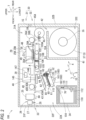
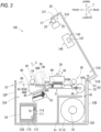
- the upper housing 31 is rotatable between a closed position illustrated in FIG. 2 and an open position illustrated in FIG. 3 around a rotation shaft 15 which is provided on a lower rear end portion and extends in the left-right direction 9.
- the slit-shaped ejection port 33 elongated in the left-right direction 9 is formed in a front surface 32F of the lower housing 32.
- An image-recorded sheet S (see FIG. 2 ) is ejected from the ejection port 33.
- An operation panel 44 is provided on a front surface 31F of the upper housing 31. A user performs an input on the operation panel 44 to operate the image recording device 100 or confirm various settings.
- the operation panel 44 includes a display portion 44A.
- the display portion 44A displays that an ink tank 34 is to be mounted in a mounting case 110, that a preservation liquid tank 11 is to be mounted in the mounting case 110, and that a waste liquid tank 77 is to be replaced.
- a holder 35, a tensioner 45, a conveying roller pair 36, a conveying roller pair 40, a head 38, a first support mechanism 51, a heater 39, a support portion 46, a second support mechanism 52, a CIS 25, a cutter unit 26, the ink tank 34, a maintenance mechanism 60, and a wiper cleaning mechanism 80 are disposed in the internal spaces 31A and 32A.
- a cleaning liquid tank 76, a liquid tank 78, the waste liquid tank 77, and a controller 130 are disposed in the internal space 32A.
- the controller 130 controls an operation of the image recording device 100.
- a partition wall 41 is provided in the internal space 32A.
- the partition wall 41 partitions a rear lower portion of the internal space 32A to define a sheet storage space 32C.
- the sheet storage space 32C is surrounded by the partition wall 41 and the lower housing 32.
- the roll body 37 is stored in the sheet storage space 32C.
- the roll body 37 includes a core tube and an elongated sheet S.
- the sheet S is wound around the core tube in a roll shape in a circumferential direction of an axis of the core tube.
- the holder 35 extending in the left-right direction 9 is located in the sheet storage space 32C.
- the holder 35 supports the roll body 37 such that the axis of the core tube of the roll body 37 extends along the left-right direction 9 and the roll body 37 is rotatable in the circumferential direction of the axis.
- the holder 35 rotates by a driving force transmitted from a conveying motor 53 (see FIG. 6 ). As the holder 35 rotates, the roll body 37 supported by the holder 35 also rotates.
- the sheet storage space 32C opens upward at a rear portion thereof.
- a gap 42 is formed between the partition wall 41 and a rear surface 32B, that is, above a rear end of the roll body 37.
- the tensioner 45 is located above the partition wall 41 in a rear portion of the internal space 32A.
- the tensioner 45 has an outer circumferential surface 45A facing an outer side of the lower housing 32.
- An upper end of the outer circumferential surface 45A is located at substantially the same up-down position as a nip D of the conveying roller pair 36 in the up-down direction 7.
- the conveying roller pair 40 is located in front of the conveying roller pair 36.
- the conveying roller pair 40 includes a conveying roller 40A and a pinch roller 40B.
- the conveying roller 40A and the pinch roller 40B abut against each other at substantially the same up-down position as the upper end of the outer circumferential surface 45A to form a nip.
- the conveying rollers 36A and 40A rotate by a driving force transmitted from the conveying motor 53 (see FIG. 6 ).
- the conveying roller pair 36 rotates while nipping the sheet S extending from the tensioner 45 in the conveying orientation 8A, thereby feeding the sheet S in the conveying orientation 8A along a conveying surface 43A of a conveying path 43 to be described later.
- the conveying roller pair 40 rotates while nipping the sheet S fed from the conveying roller pair 36, thereby feeding the sheet S in the conveying orientation 8A.
- the sheet S is pulled out from the sheet storage space 32C toward the tensioner 45 through the gap 42 by rotation of the conveying roller pairs 36 and 40.
- the conveying path 43 extending from the upper end of the outer circumferential surface 45A to the ejection port 33 is formed in the internal space 32A.
- the conveying path 43 extends substantially linearly along the conveying orientation 8A, and is a space through which the sheet Scan pass. Specifically, the conveying path 43 extends along the conveying surface 43A that spreads in the conveying orientation 8A and the left-right direction 9 and is long in the conveying orientation 8A.
- the conveying surface 43A is indicated by a two-dot chain line indicating the conveying path 43.
- the conveying path 43 is defined by a guide member (not illustrated), the head 38, a conveying belt 101, the support portion 46, the heater 39, and the like, which are located apart from one another in the up-down direction 7. That is, the head 38, the conveying belt 101, the support portion 46, and the heater 39 are located along the conveying path 43.
- the head 38 is located above the conveying path 43 and downstream of the conveying roller pair 36 in the conveying orientation 8A.
- the head 38 includes a plurality of nozzles 38A that are opened on a nozzle surface 50 (see FIGS. 4A and 4B ). Ink is discharged downward from the plurality of nozzles 38A toward the sheet S supported by the conveying belt 101. Accordingly, an image is recorded on the sheet S.
- a configuration of the head 38 will be described later.
- the first support mechanism 51 is located below the conveying path 43 and downstream of the conveying roller pair 36 in the conveying orientation 8A.
- the first support mechanism 51 is located below the head 38 and faces the head 38.
- the first support mechanism 51 includes the conveying belt 101 and a support member 104.
- the conveying belt 101 supports the sheet S, which is conveyed in the conveying orientation 8A by the conveying roller pair 36 and is located directly below the head 38.
- the conveying belt 101 conveys the supported sheet S in the conveying orientation 8A.
- the support member 104 can support the maintenance mechanism 60.
- the first support mechanism 51 includes the conveying belt 101, a drive roller 102, a driven roller 103, the support member 104, a gear 105, and a gear 106.
- the drive roller 102 and the driven roller 103 are rotatably supported by the support member 104.
- the drive roller 102 and the driven roller 103 are spaced apart from each other in the front-rear direction 8 (the conveying orientation 8A).
- the conveying belt 101 is an endless belt.
- the conveying belt 101 is stretched around the drive roller 102 and the driven roller 103.
- the conveying belt 101 is disposed in the conveying path 43 in the left-right direction 9.
- the drive roller 102 rotates by a driving force applied by the conveying motor 53 (see FIG. 6 ) to cause the conveying belt 101 to rotate.
- the driven roller 103 rotates.
- the conveying belt 101 has a conveying surface 108.
- the conveying surface 108 is a portion on an upper side of an outer circumferential surface of the conveying belt 101 and extends along the conveying orientation 8A.
- the conveying surface 108 faces the nozzles 38A of the head 38 across the conveying path 43.
- the conveying surface 108 applies a conveying force to the sheet S while supporting the sheet S conveyed between the conveying roller pairs 36 and 40 from below. Accordingly, the conveying belt 101 conveys the sheet S located in the conveying path 43 in the conveying orientation 8A along the conveying surface 108.
- the support member 104 includes a shaft 109A.
- the shaft 109A is rotatably supported by the lower housing 32.
- the shaft 109A extends in the left-right direction 9 (a direction orthogonal to the conveying orientation 8A and parallel to the nozzle surface 50 of a discharge module 49).
- the shaft 109A is provided upstream of the drive roller 102 in the conveying orientation 8A.
- the shaft 109A is located below the conveying roller pair 36.
- the shaft 109A rotates by a driving force transmitted from a shaft motor 59 (see FIG. 6 ). As the shaft 109A rotates, the support member 104 rotates around the shaft 109A. A pivot distal end 51A of the first support mechanism 51 is located downstream of the shaft 109A in the conveying orientation 8A.
- the support member 104 can change a posture thereof between a first posture (see FIG. 2 ) in which the support member 104 is parallel to the nozzle surface 50 of the discharge module 49 and a second posture (see FIG. 2 ) in which the support member 104 is parallel to the nozzle surface 50 of the discharge module 49 and a second posture (see FIG. 2 ) in which the support member 104 is parallel to the nozzle surface 50 of the discharge module 49 and a second posture (see
- FIG. 9 in which the support member 104 is inclined about the shaft 109A from the first posture and the pivot distal end 51A is located below the shaft 109A.
- the conveying surface 108 of the conveying belt 101 extends along the front-rear direction 8. Accordingly, the conveying belt 101 can convey the sheet S located in the conveying path 43 forward to the support portion 46.
- the conveying surface 108 of the conveying belt 101 extends along an inclination direction 6 that is downward toward the front.
- the inclination direction 6 is an orientation orthogonal to the left-right direction 9 and intersects the conveying orientation 8A.
- one side along the inclination direction 6 is defined as a forward inclination orientation 5, and the other side along the inclination direction 6 is defined as a backward inclination orientation 4.
- the gears 105 and 106 are rotatably supported by the support member 104 of the first support mechanism 51.
- the gear 106 is connected to a first motor 55 (see FIG. 6 ) directly or via another gear or the like, and is applied with a driving force from the first motor 55.
- the heater 39 is located below the conveying path 43, downstream of the head 38 in the conveying orientation 8A, and upstream of the conveying roller pair 40 in the conveying orientation 8A.
- the heater 39 is supported by a frame in front of the first support mechanism 51, and extends in the left-right direction 9.
- the heater 39 includes a heat transfer plate (not illustrated) and a film heater (not illustrated).
- the heat transfer plate is made of metal and has a support surface spreading in front-rear and left-right directions at substantially the same up-down position as the conveying surface 108 of the conveying belt 101.
- the sheet S fed from the first support mechanism 51 is conveyed forward on the support surface of the heat transfer plate.
- the film heater is fixed to a lower surface of the heat transfer plate and generates heat under control of the controller 130. The heat is transferred to the sheet S on the heat transfer plate via the heat transfer plate.
- the heat from the heater 39 is recovered by a duct 145 disposed above the heater 39.
- the duct 145 is disposed above the conveying path 43, downstream of the head 38 in the conveying orientation 8A, and upstream of the conveying roller pair 40.
- the duct 145 includes a suction port 146 that opens downward.
- the duct 145 includes an ejection port that opens on a left surface of the upper housing 31.
- An exhaust fan 147 is installed in the duct 145.
- a discharge port of the exhaust fan 147 faces the ejection port.
- An inlet port of the exhaust fan 147 faces the suction port 146.
- an ink mist generated when the ink is discharged from the plurality of nozzles 38A flows into the duct 145 from the suction port 146 by being carried by the airflow A, and is ejected to the outside of the housing 30 through the ejection port.
- the exhaust fan 147 is an example of a fan.
- the support portion 46 is located below the conveying path 43.
- the support portion 46 is located downstream of the head 38 and the first support mechanism 51 in the conveying orientation 8A.
- the heater 39 is located at a rear portion of the support portion 46.
- a front portion of the support portion 46 faces the conveying roller 40A.
- the support portion 46 is located upstream of the cutter unit 26 in the conveying orientation 8A.
- the support portion 46 is supported by the lower housing 32 so as to be rotatable about an axis (not illustrated) extending in the left-right direction 9. As illustrated in FIG. 3 , when the upper housing 31 is in the open position, the support portion 46 is rotatable between a laid-down position indicated by a solid line in FIG. 3 and an upright position indicated by a broken line in FIG. 3 .
- a pivot distal end 46B of the support portion 46 is located in front of a pivot base end 46A (downstream in the conveying orientation 8A).
- the support portion 46 constitutes a part of the conveying path 43 and can support the sheet S conveyed in the conveying orientation 8A by the conveying belt 101.
- the pivot distal end 46B of the support portion 46 is located higher than when the support portion 46 is in the laid-down position, and the maintenance mechanism 60 can be exposed to the outside.
- a shaft of the support portion 46 is provided at a rear end portion of the support portion 46 and extends in the left-right direction 9.
- the second support mechanism 52 is supported by the lower housing 32 so as to be movable in an orthogonal direction 10 orthogonal to the inclination direction 6 and the left-right direction 9.
- the second support mechanism 52 can support the maintenance mechanism 60.
- the second support mechanism 52 supports the maintenance mechanism 60 and slidably supports movement of the maintenance mechanism 60.
- the second support mechanism 52 is disposed in a state of extending in the inclination direction 6 as a whole, and is movable in a direction toward and away from the wiper cleaning mechanism 80 by a ball screw 160 illustrated in FIG. 2 .
- the ball screw 160 includes a screw shaft 161 and a nut member 162.
- the screw shaft 161 is supported by the lower housing 32 so as to be rotatable about an axis along the orthogonal direction 10.
- the screw shaft 161 rotates by a driving force transmitted from a vertical drive motor 163 (see FIG. 6 ).
- the nut member 162 moves upward by forward rotation of the screw shaft 161, and moves downward by reverse rotation of the screw shaft 161.
- a configuration for vertically moving the second support mechanism 52 in the orthogonal direction 10 is not limited to the configuration using the ball screw 160, and various known configurations can be adopted.
- the gears 118, 119, and 120 are rotatably supported by a main body 115 of the second support mechanism 52.
- the gear 120 meshes with the gears 118 and 119.
- the gear 120 is connected to a second motor 56 (see FIG. 6 ) directly or via another gear or the like, and is applied with a driving force from the second motor 56.
- the gears 118 and 119 can mesh with a rack 154 of the maintenance mechanism 60 located at a facing position.
- the CIS 25 is located above the conveying path 43 and downstream of the conveying roller pair 40 in the conveying orientation 8A.
- the CIS 25 can read an image on a printing surface of a sheet.
- the cutter unit 26 is located above the conveying path 43 and downstream of the CIS 25 in the conveying orientation 8A.
- the cutter unit 26 includes a cutter 28 mounted on a cutter carriage 27. As the cutter 28 moves, the sheet S located on the conveying path 43 is cut along the left-right direction 9.
- the mounting case 110 is located in the vicinity of a front end and a lower end of the lower housing 32, and has a box shape that opens toward the front.
- the ink tank 34 is inserted rearward into the mounting case 110.
- An ink needle 112 extending forward is located on a rearward end surface 111 of the mounting case 110.
- a front end of the ink needle 112 is open, and a rear end thereof is connected to the ink circuit 113.
- the ink circuit 113 connects an internal space of the ink needle 112 and the head 38 such that the ink can flow therethrough.
- the ink stored in the ink tank 34 is supplied to the head 38 through the ink needle 112 and the ink circuit 113.
- a configuration of the ink circuit 113 will be described later.
- a contact 114 is located on the end surface 111.
- the contact 114 is electrically connected to an IC substrate 70 provided on the ink tank 34 in a state in which the ink tank 34 is mounted in the mounting case 110.
- the controller 130 enables access to a storage area of the IC substrate 70 through the contact 114.
- the ink tank 34 stores ink.
- the ink is a liquid containing a pigment and the like.
- An internal space of the ink tank 34 is a storage chamber that stores ink.
- the storage chamber may be in communication with the outside in the atmosphere, or may be a bag-shape chamber such as a pouch that can contract when ink flows out.
- the ink is supplied to the head 38 from the ink tank 34 mounted in the mounting case 110 through the ink circuit 113.
- the IC substrate 70 is located on a rear surface of the ink tank 34. The IC substrate 70 stores, in the storage area, identification information indicating the ink tank 34.
- the cleaning liquid tank 76 is located below the second support mechanism 52.
- the cleaning liquid tank 76 stores a cleaning liquid containing a surfactant.
- the cleaning liquid is a liquid suitable for removing an unnecessary substance adhering to the nozzle surface 50 of the head 38.
- the surfactant is used to facilitate spreading of the cleaning liquid on a cleaning target. In other words, the surfactant is used to enhance detergency.
- the surfactant is contained in the cleaning liquid, the surfactant is regularly arranged on a surface of the bubbles, and thus a film of the bubbles is not easily broken and foaming is facilitated.
- a ratio of the surfactant to a total amount of the cleaning liquid is preferably 0.001% or more and 5.0% or less.
- the ratio of the surfactant to the total amount of the cleaning liquid is 0.01% or more and 2.0% or less. Still more preferably, the ratio of the surfactant to the total amount of the cleaning liquid is 0.01% or more and 1.0% or less. When the ratio of the surfactant to the total amount of the cleaning liquid is 0.01% or more, an effect of imparting wettability to the cleaning liquid is ensured. When the ratio of the surfactant to the total amount of the cleaning liquid is 2% or less, precipitation of a component of the cleaning liquid or an increase in viscosity of the cleaning liquid during drying is prevented.
- the surfactant is available by, for example, NEOPELEX G-15 manufactured by Kao Chemical Co., Ltd.
- the cleaning liquid may further contain, for example, an organic solvent, a preservative, a solvent, and the like.
- an organic solvent for example, glycerin is used.
- the preservative is available by, for example, Proxel GXL manufactured by Lonza Japan Ltd.
- the solvent for example, water is used.
- a cleaning liquid heating heater 303 is installed in the cleaning liquid tank 76.
- the cleaning liquid heating heater 303 heats the cleaning liquid stored in the cleaning liquid tank 76.
- a heating temperature of the cleaning liquid heating heater 303 is set to, for example, 60°C. ON/OFF of the cleaning liquid heating heater 303 is controlled by the controller 130.
- One end of a first cleaning liquid supply tube 175 is connected to the cleaning liquid tank 76.
- the one end of the first cleaning liquid supply tube 175 opens at a position lower than a liquid level of the cleaning liquid stored in the cleaning liquid tank 76.
- the other end of the first cleaning liquid supply tube 175 is connected to the maintenance mechanism 60.
- the first cleaning liquid supply tube 175 is provided with a cleaning liquid supply pump 306.
- the cleaning liquid supply pump 306 supplies the cleaning liquid from the cleaning liquid tank 76 to the maintenance mechanism 60 through the first cleaning liquid supply tube 175. Driving of the cleaning liquid supply pump 306 is controlled by the controller 130.
- a wiper cleaning valve 311 is disposed in the first cleaning liquid supply tube 175. The wiper cleaning valve 311 is located between the cleaning liquid supply pump 306 and the cleaning liquid tank 76.
- the wiper cleaning valve 311 can open and close a flow path of the first cleaning liquid supply tube 175. Opening and closing of the wiper cleaning valve 311 is controlled by the controller 130.
- One end of a cleaning liquid return tube 176 is connected to the cleaning liquid tank 76.
- the one end of the cleaning liquid return tube 176 opens at a position higher than a water level of the cleaning liquid stored in the cleaning liquid tank 76.
- the other end of the cleaning liquid return tube 176 is connected to the maintenance mechanism 60.
- a cleaning liquid introduction flow path 301 connected to an ink sub-tank 181 is connected to the cleaning liquid tank 76.
- a cleaning liquid introduction valve 302 capable of opening and closing the cleaning liquid introduction flow path 301 is disposed in the cleaning liquid introduction flow path 301. Opening and closing of the cleaning liquid introduction valve 302 is controlled by the controller 130.
- a decompression pump 193 is connected to the cleaning liquid introduction flow path 301. The decompression pump 193 depressurizes an internal space of the ink sub-tank 181 by ejecting a gas in the internal space of the ink sub-tank 181 to the outside. Driving of the decompression pump 193 is controlled by the controller 130.
- the liquid tank 78 is located below the second support mechanism 52.
- the liquid tank 78 stores a liquid containing a defoaming agent.
- the liquid is suitable for removing bubbles of the cleaning liquid.
- the liquid has a ratio of a defoaming distance to a foaming distance of 4.41% or more.
- the foaming distance (also referred to as a first height) is a height of bubbles generated when the cleaning liquid is stirred for 1 minute by a stirrer, the cleaning liquid being put into a transparent glass bottle (standard bottle No. 5) having a capacity of 50 ml, a jacket diameter (inner diameter) of 38 mm, a height of 68.5 mm, and a mouth inner diameter of 24.7 mm so as to have a height of 20 mm by a pipette.
- a regular stirrer model number: C7 ⁇ 20 manufactured by AS ONE CORPORATION can be used.
- the first height is determined by measuring, with a ruler, a length along the up-down direction 7 between a portion where an interface between the cleaning liquid and the bubbles is the lowest and a portion where the bubbles are the highest.
- the glass bottle is an example of a bottle.
- the defoaming distance is a value obtained by subtracting, from the first height of the bubbles, a height (also referred to as a second height) of bubbles after 1 ml of the liquid is dropped into the glass bottle by the pipette after the first height is determined.
- the second height is determined by measuring, with a ruler, a length along the up-down direction 7 between a portion where the interface between the cleaning liquid and the bubbles is the lowest and a portion where the bubbles are the highest.
- the first height and the second height may be an average value of maximum heights measured by the ruler when sampling is performed a plurality of times.
- the defoaming agent has a hydrophilic group and a hydrophobic group.
- the defoaming agent destroys the bubbles by penetration of defoaming agent molecules into a molecular arrangement of the surfactant in the cleaning liquid or replacement of a part of the molecular arrangement of the surfactant in the cleaning liquid with the defoaming agent molecules.
- the defoaming agent for example, those belonging to any of the group consisting of glycol ethers, silicones, and polyhydric alcohols are used.
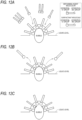
- a defoaming agent belonging to silicones Since a defoaming agent belonging to silicones has lower surface energy and weaker cohesive force than a defoaming agent belonging to other types, the defoaming agent tends to spread thinly on the surface of the bubbles as illustrated in FIGS. 11A to 11C . Therefore, even in a small amount, the defoaming agent belonging to silicones is likely to act on many surfactants arranged on the surface of the bubbles, and thus has an excellent defoaming effect of removing the bubbles of the cleaning liquid.
- the defoaming agent belonging to silicones is available by, for example, SURFYNOL (registered trademark) DF-58 manufactured by Nissin Chemical Industry Co., Ltd., and BYK-093, BYK-024, BYK-025, and BYK-1650 manufactured by BYK Japan KK.
- SURFYNOL registered trademark
- the defoaming agent belonging to polyhydric alcohols has excellent defoaming effect since the defoaming agent belonging to polyhydric alcohols easily satisfies any of the following matters: having a hydrophilic group having a large affinity to water; and having a small surface energy.
- the affinity of the hydrophilic group contained in the defoaming agent to water is large, since the hydrophilic group of the defoaming agent is likely to bond to a film constituting the bubbles, as illustrated in FIGS.
- the defoaming agent is likely to approach the film of the bubbles, and a part of the molecular arrangement of the surfactant and the defoaming agent molecules are likely to be replaced.
- the defoaming agent is likely to spread thinly on the surface of the bubbles of the cleaning liquid, and thus is likely to act on the surfactant.
- Examples of the defoaming agent belonging to polyhydric alcohols include 1,2-hexanediol (1,2-HDL), 1,2-butanediol, 1,4-butanediol, 2-ethyl-1, and 3-hexanediol, and Surfynol AD01 manufactured by Nissin Chemical Industry Co., Ltd.
- a ratio of the defoaming agent belonging to polyhydric alcohols to the total amount of the liquid is preferably 6% or more. More preferably, the ratio of the defoaming agent belonging to polyhydric alcohols to the total amount of the liquid is 10% or more.
- the defoaming agent belonging to glycol ethers has excellent defoaming effect since the defoaming agent belonging to glycol ethers easily satisfies any of the following matters: having a hydrophilic group having a large affinity to water; and having a small surface energy.
- the affinity of the hydrophilic group contained in the defoaming agent to water is large, since the hydrophilic group of the defoaming agent is likely to bond to a film constituting the bubbles, as illustrated in FIGS.
- the defoaming agent is likely to approach the film of the bubbles, and a part of the molecular arrangement of the surfactant and the defoaming agent molecules are likely to be replaced.
- the defoaming agent is likely to spread thinly on the surface of the bubbles of the cleaning liquid, and thus is likely to act on the surfactant.
- Examples of the defoaming agent belonging to glycol ethers include triethylene glycol monobutyl ether (BTG), dipropylene glycol monopropyl ether (PFDG), dipropyleneglycol monobutyl ether (BFDG), diethylene glycol monobutyl ether (BDG), and propylene glycol monobutyl ether (PnB).
- a ratio of the defoaming agent belonging to glycol ethers to the total amount of the liquid is preferably 20% or more. More preferably, the ratio of the defoaming agent belonging to glycol ethers to the total amount of the liquid is 30% or more.
- the solvent for example, water is used.
- a liquid heating heater 192 is installed in the liquid tank 78.
- the liquid heating heater 192 heats the liquid stored in the liquid tank 78.
- a heating temperature of the liquid heating heater 192 is set to, for example, 60°C. ON/OFF of the liquid heating heater 192 is controlled by the controller 130.
- One end of a first liquid supply tube 179 is connected to the liquid tank 78.
- the one end of the first liquid supply tube 179 opens at a position higher than the liquid level of the liquid stored in the liquid tank 78.
- the other end of the first liquid supply tube 179 is connected to the maintenance mechanism 60.
- the first liquid supply tube 179 is provided with a first liquid supply pump 180.
- the first liquid supply pump 180 supplies the liquid in the liquid tank 78 to the maintenance mechanism 60 through the first liquid supply tube 179.
- Driving of the first liquid supply pump 180 is controlled by the controller 130.
- a first liquid supply valve 201 is disposed in the first liquid supply tube 179.
- the first liquid supply valve 201 is located between the liquid tank 78 and the first liquid supply pump 180.
- the first liquid supply valve 201 can open and close a flow path of the first liquid supply tube 179. Opening and closing of the first liquid supply tube 179 is controlled by the controller 130.
- One end of a liquid return tube 202 is connected to the liquid tank 78. The one end of the liquid return tube 202 opens at a position lower than the liquid level of the liquid stored in the liquid tank 78. The other end of the liquid return tube 202 is connected to the maintenance mechanism 60.
- the waste liquid tank 77 is a container from which the cleaning liquid is ejected, and is in communication with the outside in the atmosphere.
- the waste liquid tank 77 is provided with a liquid level sensor 308.
- the liquid level sensor 308 is an optical sensor.
- the liquid level sensor 308 detects presence or absence of a waste liquid at a predetermined height in an internal space of the waste liquid tank 77.
- the liquid level sensor 308 outputs a detection signal to the controller 130.
- the liquid level sensor 308 outputs an ON signal as the detection signal when the cleaning liquid is detected, and outputs an OFF signal as the detection signal when the cleaning liquid is not detected.
- the controller 130 determines whether the liquid level reaches the predetermined height in the internal space of the waste liquid tank 77 based on the detection signal output from the liquid level sensor 308.
- a third liquid level sensor is not particularly limited as long as the third liquid level sensor can detect the presence or absence of the waste liquid at the predetermined height.
- the third liquid level sensor may be a transmission-type optical sensor
- a liquid spray device 203 is provided in the waste liquid tank 77.
- the liquid spray device 203 is located on a lower surface of an upper wall of the waste liquid tank 77.
- the liquid spray device 203 sprays the liquid supplied from the liquid tank 78 downward in a form of a mist.
- One end of a second liquid supply tube 204 is connected to the liquid spray device 203.
- the other end of the second liquid supply tube 204 is connected to the liquid tank 78.
- the other end of the second liquid supply tube 204 opens at a position lower than the liquid level of the liquid stored in the liquid tank 78.
- a second liquid supply pump 205 is provided in the second liquid supply tube 204.
- the second liquid supply pump 205 supplies the liquid in the liquid tank 78 to the liquid spray device 203 through the second liquid supply tube 204. Driving of the second liquid supply pump 205 is controlled by the controller 130.
- a second liquid supply valve 206 is disposed in the second liquid supply tube 204. The second liquid supply valve 206 is located between the liquid tank 78 and the second liquid supply pump 205. The second liquid supply valve 206 can open and close a flow path of the second liquid supply tube 204. Opening and closing of the second liquid supply tube 204 is controlled by the controller 130.
- the maintenance mechanism 60 is for executing maintenance of the head 38.
- the maintenance mechanism 60 is configured to be movable, and is moved to a position directly below the head 38 when the maintenance of the head 38 is executed (see FIG. 7 ).
- the maintenance of the head 38 includes a purge process, a cap cleaning process, and a wiping process.
- the purge process is a process of covering the plurality of nozzles 38A with a cap 62 to be described later of the maintenance mechanism 60, and sucking ink from the plurality of nozzles 38A by a suction pump 74.
- the cap cleaning process is a process of cleaning the nozzle surface 50 of the head 38 with the cleaning liquid fed into an internal space 67 of the cap 62 in a state in which the nozzles 38A are covered with the cap 62. As illustrated in FIG.
- the wiping process is a process of wiping the nozzle surface 50 of the head 38 with later-described first sponge wiper 64, second sponge wiper 65, and rubber wiper 63 of the maintenance mechanism 60.
- a configuration of the maintenance mechanism 60 will be described later.
- the wiper cleaning mechanism 80 is for cleaning the cap 62 and the rubber wiper 63 of the maintenance mechanism 60.
- the maintenance mechanism 60 is moved directly below the wiper cleaning mechanism 80 when the cap 62 and the rubber wiper 63 are cleaned.
- a surface of the wiper cleaning mechanism 80 facing the maintenance mechanism 60 is formed by sponge and holds a maintenance liquid.
- the wiper cleaning mechanism 80 can abut against the cap 62, the first sponge wiper 64, the second sponge wiper 65, and the rubber wiper 63 located at a retraction position. Accordingly, the wiper cleaning mechanism 80 wipes ink adhered to the cap 62, the first sponge wiper 64, the second sponge wiper 65, and the rubber wiper 63.
- the head 38 has a rectangular parallelepiped shape elongated substantially in the left-right direction 9.
- the head 38 includes a frame 48 and the discharge module 49.
- the number of the discharge module 49 is not limited to one, and may be, for example, plural.
- the discharge module 49 is supported by the frame 48. A lower surface of the discharge module 49 is exposed downward.
- the discharge module 49 is disposed in the conveying path 43 in the left-right direction 9.
- the discharge module 49 includes the plurality of nozzles 38A. Each nozzle 38A is opened on the nozzle surface 50 of the discharge module 49.
- the nozzle surface 50 is a surface spreading in the front-rear direction 8 and the left-right direction 9. As described above, the ink is discharged downward from the plurality of nozzles 38A toward the sheet S supported by the conveying belt 101 of the first support mechanism 51, and an image is recorded on the sheet S.
- the discharge module 49 includes an inflow port 22 and an outflow port 23 connected to the ink circuit 113.
- the inflow port 22 and the outflow port 23 are connected to a manifold 24, respectively.
- the manifold 24 is connected to the plurality of nozzles 38A.
- Ink that has flowed into the manifold 24 through the inflow port 22 is discharged to the outside through the nozzles 38A by piezoelectric elements (not illustrated) located corresponding to the respective nozzles 38A being driven.
- the ink in the manifold 24 can circulate through the inflow port 22 and the outflow port 23.
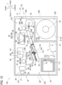
- the head 38 moves along the up-down direction 7 to a recording position illustrated in FIGS. 9 and 10 , a capped position illustrated in FIG. 7 , a wiped position indicated by a solid line in FIG. 8 , and an uncapped position indicated by a broken line in FIG. 8 .
- the recording position is a position of the head 38 when the image is recorded on the sheet S supported by the conveying belt 101.
- the capped position is a position of the head 38 when the discharge module 49 is covered with the cap 62 of the maintenance mechanism 60.
- the capped position is a position above the recording position (a position farther from the first support mechanism 51 than the recording position).
- the wiped position is a position of the head 38 when the first sponge wiper 64 and the second sponge wiper 65 of the maintenance mechanism 60 wipe the nozzle surface 50 of the discharge module 49.
- the wiped position is a position above the capped position.
- the uncapped position is a position of the head 38 when the head 38 is completely separated from the maintenance mechanism 60.
- the uncapped position is a position above the wiped position.
- the head 38 is moved by a ball screw 29.
- the ball screw 29 includes a screw shaft 29A and a nut member 29B.
- the screw shaft 29A is supported by the lower housing 32 so as to be rotatable about an axis along the up-down direction 7.
- the screw shaft 29A rotates by a driving force transmitted from a head motor 54 (see FIG. 6 ).
- the nut member 29B moves upward by forward rotation of the screw shaft 29A, and moves downward by reverse rotation of the screw shaft 29A.
- a configuration for allowing the head 38 to vertically move is not limited to the configuration using the ball screw 29, and various known configurations can be adopted.
- the maintenance mechanism 60 includes a support base 61, the first sponge wiper 64, the second sponge wiper 65, the rubber wiper 63, and the cap 62.
- the maintenance mechanism 60 is supported by the first support mechanism 51 and the second support mechanism 52 in the second posture.
- the support base 61 has a box shape with an opening at the top.
- the support base 61 is provided with the rack 154.
- the rack 154 is located on a lower surface of a bottom wall of the support base 61.
- the rack 154 is located on the lower surface of the bottom wall of the support base 61 over the entire surface in the inclination direction 6.
- the rack 154 can mesh with the gear 105 of the first support mechanism 51.
- the maintenance mechanism 60 slides in the front-rear direction 8 along the upper surface of the first support mechanism 51 in the first posture.
- the rack 154, the gears 105 and 106, and the first motor 55 are an example of a moving mechanism that causes the head and the support body to relatively move along the first direction.
- the support base 61 is an example of the support body.
- the rack 154 can mesh with the gears 118 and 119 of the second support mechanism 52.
- the driving force of the first motor 55 is transmitted to the gears 118 and 119 via the gear 120 in a state in which the rack 154 is meshed with at least one of the gears 118 and 119, the maintenance mechanism 60 slides in the inclination direction 6 along an upper surface of the second support mechanism 52.
- the maintenance mechanism 60 is movable to a standby position illustrated in FIG. 2 , a retraction position indicated by a broken line in FIG. 8 , a maintenance position illustrated in FIG. 7 , and a wiping position illustrated in FIG. 8 .
- the maintenance mechanism 60 at the maintenance position and the wiping position faces the nozzle surface 50 of the discharge module 49 of the head 38 in the up-down direction 7.
- the maintenance mechanism 60 at the standby position and the retraction position is in a state of being separated from the nozzle surface 50.
- a cleaning liquid flow path 61A connecting the other end of the first cleaning liquid supply tube 175 and the other end of the cleaning liquid return tube 176 is formed on an upper surface of the bottom wall of the support base 61 (see FIG. 5 ).
- the cleaning liquid flow path 61A has a recessed shape recessed downward from the upper surface of the bottom wall of the support base 61. Accordingly, the cleaning liquid supplied to the maintenance mechanism 60 through the first cleaning liquid supply tube 175 by driving of the cleaning liquid supply pump 306 flows through the cleaning liquid flow path 61A. The cleaning liquid flowing through the cleaning liquid flow path 61A is returned to the cleaning liquid tank 76 through the cleaning liquid return tube 176.
- a liquid flow path 61B connecting the other end of the first liquid supply tube 179 and the other end of the liquid return tube 202 is formed on the upper surface of the bottom wall of the support base 61.
- the liquid flow path 61B has a recessed shape recessed downward from the upper surface of the bottom wall of the support base 61. Accordingly, the liquid supplied to the maintenance mechanism 60 through the first liquid supply tube 179 by driving of the first liquid supply pump 180 flows through the liquid flow path 61B. The liquid flowing through the liquid flow path 61B is returned to the liquid tank 78 through the liquid return tube 202.
- the first sponge wiper 64 is supported by the support base 61.
- the first sponge wiper 64 is formed by sponge.
- the first sponge wiper 64 has a rectangular parallelepiped shape that is longer in the left-right direction 9 than in the up-down direction 7 and the inclination direction 6.
- a length of the first sponge wiper in the left-right direction 9 is longer than a length of the nozzle surface 50 in the left-right direction 9.
- the first sponge wiper 64 is held by a first holding fixture fixed to the upper surface of the bottom wall of the support base 61 in a state in which a lower end portion thereof is located in the cleaning liquid flow path 61A.
- the first sponge wiper 64 absorbs the cleaning liquid by coming into contact with the cleaning liquid flowing through the cleaning liquid flow path 61A. As a result, the first sponge wiper 64 is in a state of being impregnated with the cleaning liquid. The cleaning liquid not absorbed by the first sponge wiper 64 is returned to the cleaning liquid tank 76 through the cleaning liquid return tube 176.
- the first holding fixture is not particularly limited as long as the first holding fixture can hold the first sponge wiper on the support base 61 in a state in which the lower end portion of the first sponge wiper 64 is located in the cleaning liquid flow path 61A.
- a plurality of first sponge wipers 64 may be provided in accordance with the number of discharge module 49.
- the number of the discharge module 49 is three
- three first sponge wipers 64 may be provided in accordance with each discharge module 49.
- the first sponge wiper 64 is an example of the first wiper.
- the second sponge wiper 65 is supported by the support base 61.
- the second sponge wiper 65 is located in the backward inclination orientation 4 of the first sponge wiper 64 at an interval.
- the above-mentioned interval is set such that the second sponge wiper 65 immediately passes through a space through which the first sponge wiper 64 has passed when the support base 61 moves in the conveying orientation 8A.
- the above-mentioned interval is set such that the second sponge wiper 65 passes through the space through which the first sponge wiper 64 has passed within five seconds when the support base 61 moves in the conveying orientation 8A.
- the above-mentioned interval is, for example, 5 cm or less.
- the second sponge wiper 65 is formed by sponge.
- the second sponge wiper 65 has the same shape and size as the first sponge wiper 64.
- the second sponge wiper 65 has a rectangular parallelepiped shape that is longer in the left-right direction 9 than in the up-down direction 7 and the inclination direction 6.
- a length of the second sponge wiper 65 in the left-right direction 9 is longer than the length of the nozzle surface 50 in the left-right direction 9.
- the second sponge wiper 65 is held by a second holding fixture fixed to the upper surface of the bottom wall of the support base 61 in a state in which a lower end portion thereof is located in the liquid flow path 61B. Accordingly, the second sponge wiper 65 absorbs the liquid by coming into contact with the liquid flowing through the liquid flow path 61B. As a result, the second sponge wiper 65 is in a state of being impregnated with the liquid containing the defoaming agent.
- the liquid not absorbed by the second sponge wiper 65 is returned to the liquid tank 78 through the
- the second holding fixture is not particularly limited as long as the second holding fixture can hold the second sponge wiper 65 on the support base 61 in a state in which the lower end portion of the second sponge wiper 65 is located in the liquid flow path 61B.
- a plurality of second sponge wipers 65 may be provided in accordance with the number of the discharge module 49.
- the number of the discharge module 49 is three
- three second sponge wipers 65 may be provided in accordance with each discharge module 49.
- the second sponge wiper 65 is an example of the second wiper.
- the rubber wiper 63 is supported by the support base 61.
- the rubber wiper 63 is located in the backward inclination orientation 4 of the second sponge wiper 65 at an interval.
- the rubber wiper 63 is formed by rubber.
- the rubber wiper 63 has a flat plate shape that is longer in the left-right direction 9 than in the up-down direction 7 and the inclination direction 6.
- a length of the rubber wiper 63 in the left-right direction 9 is longer than the length of the nozzle surface 50 in the left-right direction 9.
- An upper end portion of the rubber wiper 63 is formed such that a thickness thereof is reduced as it extends upward.
- the rubber wiper 63 is held by a third holding fixture fixed to the upper surface of the bottom wall of the support base 61.
- the third holding fixture is not particularly limited as long as the third holding fixture can hold the rubber wiper 63 on the support base 61.
- the first holding fixture, the second holding fixture, and the third holding fixture may be integrated.
- a plurality of rubber wipers 63 may be provided in accordance with the number of the discharge module 49.
- three rubber wipers 63 may be provided in accordance with each discharge module 49.
- the cap 62 is supported by the support base 61.
- the cap 62 is located in the forward inclination orientation 5 of the first sponge wiper 64 at an interval.
- the cap 62 has a box shape with an open top.
- the cap 62 is formed of an elastic body such as rubber or silicon.
- the cap 62 can face the discharge module 49.
- the cap 62 abuts against the nozzle surface 50 to seal the internal space 67 of the cap 62 (see FIG. 5 ). Accordingly, the cap 62 is in a state of covering the plurality of nozzles 38A.
- the cap 62 includes a supply flow path 20 and an ejection flow path 21.
- the supply flow path 20 and the ejection flow path 21 allow the internal space 67 of the cap 62 to communicate with the outside.
- One end of a second cleaning liquid supply tube 177 is connected to the supply flow path 20.
- the other end of the second cleaning liquid supply tube 177 is connected to the cleaning liquid tank 76.
- the other end of the second cleaning liquid supply tube 177 opens at a position lower than the liquid level of the cleaning liquid stored in the cleaning liquid tank 76.
- a cap cleaning valve 72 is provided in the second cleaning liquid supply tube 177.
- the cap cleaning valve 72 can open and close a flow path of the second cleaning liquid supply tube 177. Opening and closing of the cap cleaning valve 72 is controlled by the controller 130.
- a suction pump 74 is provided in the waste liquid tube 178. When the suction pump 74 is driven in a state in which the cap 62 abuts against the nozzle surface 50 and the cap cleaning valve 72 is opened, the internal space 67 of the cap 62 becomes a negative pressure, and thus the cleaning liquid in the cleaning liquid tank 76 is supplied to the internal space 67 of the cap 62 through the second cleaning liquid supply tube 177.
- the cleaning liquid supplied to the internal space 67 of the cap 62 comes into contact with the nozzle surface 50 to clean the nozzle surface 50.
- the cleaning liquid that has cleaned the nozzle surface 50 is ejected to the waste liquid tank through the waste liquid tube 178.
- Driving of the suction pump 74 is controlled by the controller 130.
- a plurality of caps 62 may be provided in accordance with the number of the discharge module 49.
- the number of the discharge module 49 is three, three caps 62 may be provided in accordance with each discharge module 49.
- the ink circuit 113 includes the ink sub-tank 181, flow paths 182, 183, and 184, an atmospheric flow path 185, a bypass flow path 186, a replenishment valve 187, a purge shutoff valve 188, a bypass valve 189, an atmospheric release valve 190, and a positive pressure pump 191.
- the ink sub-tank 181 is located above the mounting case 110 in the internal space of the housing 30.
- the ink sub-tank 181 stores ink in an internal space thereof.
- the internal space of the ink sub-tank 181 communicates with the ink needle 112 of the mounting case 110 through the flow path 182.
- the replenishment valve 187 is located in the flow path 182.
- the replenishment valve 187 is controlled by the controller 130 to open and close the flow path 182.
- the ink stored in the internal space of the ink sub-tank 181 can be supplied to the discharge module 49 through the flow path 183.
- the positive pressure pump 191 is located in the flow path 183.
- the positive pressure pump 191 is operated by the controller 130 controlling driving of a pump motor 138 (see FIG. 6 ).
- the ink in the manifold 24 of the discharge module 49 can be ejected to the ink sub-tank 181 through the flow path 184.
- the purge shutoff valve 188 is located in the flow path 184. The purge shutoff valve 188 is controlled by the controller 130 to open and close the flow path 184.
- the bypass flow path 186 is connected between the positive pressure pump 191 and the inflow port 22 in the flow path 183 and between the purge shutoff valve 188 and the ink sub-tank 181 in the flow path 184.
- the bypass valve 189 is located in the bypass flow path 186.
- the bypass valve 189 is controlled by the controller 130 to open and close the bypass flow path 186.
- the internal space of the ink sub-tank 181 communicates with the outside through the atmospheric flow path 185.
- the atmospheric release valve 190 is located in the atmospheric flow path 185.
- the atmospheric release valve 190 is controlled by the controller 130 to open and close the atmospheric flow path 185.
- the controller 130 includes a CPU 131, a ROM 132, a RAM 133, an EEPROM 134, and an ASIC 135, which are connected by an internal bus 137.
- the ROM 132 stores programs for controlling various operations of the CPU 131.
- the RAM 133 is used as a storage area for temporarily storing data, signals, and the like used when the CPU 131 executes the above-mentioned programs, or as a work area for data processing.
- the EEPROM 134 stores settings, flags, and the like to be held even after power is turned off.
- the conveying motor 53, the head motor 54, the first motor 55, the second motor 56, the cleaning liquid supply pump motor 307, the first liquid supply pump motor 309, the second liquid supply pump motor 310, the suction pump motor 58, the pump motors 138 and 139, the shaft motor 59, and the vertical drive motor 163 are connected to the ASIC 135.
- the cap cleaning valve 72, the replenishment valve 187, the purge shutoff valve 188, the bypass valve 189, the atmospheric release valve 190, the cleaning liquid introduction valve 302, the wiper cleaning valve 311, the first liquid supply valve 201, and the second liquid supply valve 206 are connected to the ASIC 135.
- Each valve is connected to the ASIC 135 via a drive circuit for driving the valve.
- the ASIC 135 generates a drive signal for causing each motor to rotate, and controls each motor based on the drive signal. Each motor rotates forward or backward according to the drive signal from the ASIC 135.
- the controller 130 controls driving of the conveying motor 53 to cause the holder 35, the conveying roller 36A, the conveying roller 40A, and the drive roller 102 to rotate.
- the controller 130 controls driving of the head motor 54 to cause the screw shaft 29A to rotate and cause the head 38 to move in the up-down direction 7.
- the controller 130 controls driving of the shaft motor 59 to cause the first support mechanism 51 to rotate.
- the controller 130 controls driving of the first motor 55 to cause the gear 106 of the first support mechanism 51 to rotate.
- the controller 130 controls driving of the vertical drive motor 163 to cause the screw shaft 161 to rotate and cause the second support mechanism 52 to move along the orthogonal direction 10.
- the controller 130 controls driving of the second motor 56 to cause the gear 120 of the second support mechanism 52 to rotate.
- the controller 130 controls driving of the cleaning liquid supply pump motor 307 to drive the cleaning liquid supply pump 306.
- the controller 130 controls driving of the first liquid supply pump motor 309 to drive the first liquid supply pump 180.
- the controller 130 controls driving of the second liquid supply pump motor 310 to drive the second liquid supply pump 205.
- the controller 130 controls driving of the suction pump motor 58 to drive the suction pump 74.
- the controller 130 controls driving of the pump motor 138 to drive the positive pressure pump 191.
- the controller 130 controls driving of the pump motor 139 to drive the decompression pump 193.
- the operation panel 44, the display portion 44A, the contact 114, the liquid level sensor 308, and a piezoelectric element are connected to the ASIC 35.
- the operation panel 44 outputs an operation signal corresponding to an operation by the user to the controller 130.
- the operation panel 44 may include, for example, a push button, or a touch sensor superimposed on a display.
- the controller 130 reads the identification information from the storage area of the IC substrate 70 of the ink tank 34 through the contact 114.
- the controller 130 causes the display portion 44A to display that the ink tank 34 is mounted in the mounting case 110 based on the identification information.
- the controller 130 receives a detection signal from the liquid level sensor 308.
- the controller 130 causes the display portion 44A to display that the waste liquid tank 77 is to be replaced based on the detection signal from the liquid level sensor 308.
- the piezoelectric element operates by being supplied with power from the controller 130 via a drive circuit (not illustrated).
- the controller 130 controls the power supply to the piezoelectric element, and causes ink droplets to be selectively discharged from the plurality of nozzles 38A.
- the image recording device 100 When the image recording process is not executed, the image recording device 100 is in a standby state.
- the standby state as illustrated in FIG. 7 , the head 38 is located at the capped position, the first support mechanism 51 is located in the first posture in a state of supporting the maintenance mechanism 60, and the maintenance mechanism 60 is located at the maintenance position.
- the cap 62 covers the plurality of nozzles 38A by abutting against the nozzle surface 50.
- the controller 130 executes the purge process at a predetermined timing or when a command from the outside is received.
- a description will be given of a process executed when the controller 130 receives a command to execute the purge process from the outside while the image recording device 100 is in the standby state.
- the controller 130 drives the suction pump 74 in a state in which the purge shutoff valve 188 and the bypass valve 189 are opened and the replenishment valve 187, the atmospheric release valve 190, and the cap cleaning valve 72 are closed. Accordingly, the ink in the plurality of nozzles 38A is sucked into the internal space 67 of the cap 62 and ejected to the waste liquid tank 77 through the waste liquid tube 178. In this case, since the cap cleaning valve 72 is closed, the cleaning liquid is not supplied from the cleaning liquid tank 76 to the cap 62 through the second cleaning liquid supply tube 177.
- the controller 130 executes the cleaning process. Specifically, the controller 130 first drives the suction pump 74 in a state in which the cap cleaning valve 72 is opened and the replenishment valve 187, the purge shutoff valve 188, the bypass valve 189, and the atmospheric release valve 190 are closed. Accordingly, the cleaning liquid is supplied from the cleaning liquid tank 76 to the internal space 67 of the cap 62 through the second cleaning liquid supply tube 177. As a result, the nozzle surface 50 is cleaned by being immersed with the cleaning liquid. In this case, since the purge shutoff valve 188 and the bypass valve 189 are closed, the ink is not ejected from the plurality of nozzles 38A of the head 38 to the internal space 67 of the cap 62.
- the controller 130 moves the head 38 to the uncapped position, and then drives the suction pump 74 in a state in which the cap cleaning valve 72 is closed. Accordingly, the cleaning liquid is ejected from the internal space 67 of the cap 62 into the waste liquid tank 77 through the waste liquid tube 178. As a result, the ink remaining in the internal space 67 of the cap 62 and the waste liquid tube 178 is washed away by the cleaning liquid. In this case, since the cleaning liquid contains a surfactant in order to enhance the detergency, bubbles of the cleaning liquid may be generated in the waste liquid tank 77. When the bubbles of the cleaning liquid increase in the waste liquid tank 77, detection accuracy of the liquid level sensor 308 is reduced.
- the controller 130 causes the second liquid supply pump 205 to operate by driving the second liquid supply pump motor 310 in a state in which the second liquid supply valve 206 is opened. Accordingly, the liquid containing the defoaming agent in the liquid tank 78 is supplied to the liquid spray device 203 through the second liquid supply tube 204.
- the liquid spray device 203 to which the liquid is supplied sprays the liquid downward in a form of a mist. As a result, the defoaming agent comes into contact with the bubbles of the cleaning liquid in the waste liquid tank 77, and thus the bubbles of the cleaning liquid disappear.
- the waste liquid tank 77 is an example of the predetermined portion.
- the controller 130 executes the wiping process. Specifically, the controller 130 first executes a heating process. In the heating process, the controller 130 first turns on the cleaning liquid heating heater 303 and the liquid heating heater 192. Accordingly, the cleaning liquid stored in the cleaning liquid tank 76 is heated by the cleaning liquid heating heater 303. At the same time, the liquid stored in the liquid tank 78 is heated by the liquid heating heater 192.
- the controller 130 causes the cleaning liquid supply pump 306 to operate by driving the cleaning liquid supply pump motor 307 in a state in which the wiper cleaning valve 311 is opened. Accordingly, the cleaning liquid in the cleaning liquid tank 76 circulates between the first sponge wiper 64 and the cleaning liquid tank 76 through the first cleaning liquid supply tube 175, the cleaning liquid flow path 61A of the support base 61, and the cleaning liquid return tube 176. In this case, a part of the cleaning liquid flowing through the cleaning liquid flow path 61A is absorbed by the first sponge wiper 64 by coming into contact with the lower end portion of the first sponge wiper 64. Accordingly, the first sponge wiper 64 is in a state of being impregnated with the cleaning liquid. The first sponge wiper 64 that is impregnated with the cleaning liquid is heated by heat transferred from the cleaning liquid. The process of heating the first sponge wiper 64 with the cleaning liquid is an example of the heating process.
- the controller 130 causes the first liquid supply pump 180 to operate by driving the first liquid supply pump motor 309 in a state in which the first liquid supply valve 201 is opened. Accordingly, the liquid in the liquid tank 78 circulates between the second sponge wiper 65 and the liquid tank 78 through the first liquid supply tube 179, the liquid flow path 61B of the support base 61, and the liquid return tube 202. In this case, a part of the liquid flowing through the liquid flow path 61B is absorbed by the second sponge wiper 65 by coming into contact with the lower end portion of the second sponge wiper 65. Accordingly, the second sponge wiper 65 is in a state of being impregnated with the liquid. The second sponge wiper 65 that is impregnated with the liquid is heated by heat transferred from the liquid. The process of heating the second sponge wiper 65 with the liquid is an example of the heating process.
- the controller 130 causes the head 38 to move downward so as to move from the uncapped position indicated by the broken line to the wiped position indicated by the solid line in FIG. 8 .
- the maintenance mechanism 60 is in the maintenance position indicated by the broken line in FIG. 8 .
- the controller 130 drives the first motor 55 to cause the gear 106 to rotate clockwise in FIG. 8 .
- the gear 105 rotates counterclockwise in FIG. 8 .
- the maintenance mechanism 60 at the maintenance position moves forward (downstream in the conveying orientation 8A) along the conveying orientation 8A and reaches the wiping position (see FIG. 8 ).
- the upper end portions of the first sponge wiper 64, the second sponge wiper 65, and the rubber wiper 63 slide in the conveying orientation 8A with respect to the nozzle surface 50 while abutting against the nozzle surface 50 of the discharge module 49. Accordingly, the nozzle surface 50 is wiped by the first sponge wiper 64, the second sponge wiper 65, and the rubber wiper 63, thereby removing a foreign matter adhering to the nozzle surface 50. In this case, bubbles of the cleaning liquid may be generated on the nozzle surface 50 by a wiping operation of the first sponge wiper 64.
- the nozzle surface 50 is wiped by the second sponge wiper 65 that is impregnated with the liquid containing the defoaming agent immediately after being wiped by the first sponge wiper 64 (for example, within five seconds), the bubbles of the cleaning liquid generated on the nozzle surface 50 immediately disappear by coming into contact with the liquid containing the defoaming agent. Since the nozzle surface 50 is wiped by the rubber wiper 63 immediately after being wiped by the second sponge wiper 65, the cleaning liquid and the liquid remaining on the nozzle surface 50 are removed by a wiping operation of the rubber wiper 63.
- the conveying orientation 8A is an example of the one direction.
- the nozzle surface 50 is an example of the predetermined portion.
- the process of wiping the nozzle surface 50 by the first sponge wiper 64 is an example of a first supply process.
- the first supply process is an example of supplying the cleaning liquid.
- the process of wiping the nozzle surface 50 by the second sponge wiper 65 is an example of a second supply process.
- the second supply process is an example of supplying the liquid.
- the controller 130 drives the head motor 54 to cause the head 38 to move to the uncapped position indicated by the broken line in FIG. 8 .
- the controller 130 drives the first motor 55 to cause the gear 106 to rotate counterclockwise in FIG. 8 .
- the gear 106 rotates counterclockwise
- the gear 105 rotates clockwise in FIG. 8 .
- the maintenance mechanism 60 moves rearward (upstream in the conveying orientation 8A) and reaches the maintenance position.
- the controller 130 causes the head 38 to move from the uncapped position to the capped position (see FIG. 7 ).
- the controller 130 ends the wiping process.
- the controller 130 causes the maintenance mechanism 60 to move to the retreat position. Specifically, the controller 130 first drives the shaft motor 59 to change the posture of the first support mechanism 51 from the first posture to the second posture (see FIG. 9 ).
- the controller 130 drives the first motor 55. Accordingly, as the gear 106 rotates clockwise in FIG. 9 , the gear 105 rotates counterclockwise in FIG. 9 . As a result, the maintenance mechanism 60 moves in the forward inclination orientation 5 and is transferred onto the second support mechanism 52.
- the controller 130 drives the second motor 56. Accordingly, as the gear 120 rotates clockwise, the gears 118 and 119 rotate counterclockwise. As a result, the maintenance mechanism 60 reaches the standby position on the second support mechanism 52 (see FIG. 10 ).
- the controller 130 drives the vertical drive motor 163. Accordingly, as the screw shaft 161 of the ball screw 160 rotates, the second support mechanism 52 moves upward from the standby position along the orthogonal direction 10, and the maintenance mechanism 60 reaches the retraction position. Accordingly, the cap 62, the first sponge wiper 64, the second sponge wiper 65, and the rubber wiper 63 abut against the wiper cleaning mechanism 80.
- the controller 130 When the controller 130 receives a command to record an image on the sheet S from outside of the operation panel 44, an information processing device connected to the image recording device 100 via a LAN or the like, and the like, the controller 130 causes the maintenance mechanism 60 to move from the maintenance position to the retreat position as described above.
- the controller 130 drives the shaft motor 59 to change the posture of the first support mechanism 51 from the second posture to the first posture.
- the controller 130 causes the head 38 to move downward so as to move from the capped position to the recording position.
- the controller 130 drives the conveying motor 53 to cause the holder 35, the conveying roller 36A, the conveying roller 40A, and the drive roller 102 to rotate. Accordingly, conveyance of the sheet S is started, and the sheet S reaches directly below the head 38.
- the controller 130 drives the pump motors 138 and 139 in a state in which the bypass valve 189 and the cleaning liquid introduction valve 302 are closed and the purge shutoff valve 188 is opened. Accordingly, a pressure difference is generated between the discharge module 49 and the ink sub-tank 181 due to operations of the positive pressure pump 191 and the decompression pump 193.
- the ink is discharged from the plurality of nozzles 38A while circulating through the flow paths 183 and 184 between the ink sub-tank 181 and the discharge module 49. Accordingly, an image is recorded on the sheet S.
- the ink adhering to the sheet S is fixed to the sheet S by being heated when passing through the heater 39. After the sheet S having passed through the heater 39 is further conveyed in the conveying orientation 8A by the conveying roller pair 40, and the image recorded by the CIS 25 is checked, the sheet S is cut into a predetermined size by the cutter unit 26 and ejected from the ejection port 33.
- the liquid containing the defoaming agent is supplied to the predetermined portion. Therefore, the bubbles of the cleaning liquid are removed by the defoaming agent coming into contact with the bubbles of the cleaning liquid. Therefore, a failure of the image recording device 100 due to the bubbles of the cleaning liquid can be prevented. Since the liquid of which the ratio of the defoaming distance to the foaming distance is 4.41% or more is supplied to the predetermined portion, it is possible to remove all the bubbles of the cleaning liquid from the predetermined portion by using a small amount of the liquid.
- the defoaming agent belongs to any of the group consisting of glycol ethers, silicones, and polyhydric alcohols. Therefore, the defoaming effect of the defoaming agent removing the bubbles of the cleaning liquid is improved.
- the liquid contains the defoaming agent belonging to glycol ethers in a ratio of 20% or more, the defoaming effect of the defoaming agent removing the bubbles of the cleaning liquid is high.
- the defoaming agent belonging to glycol ethers is contained in a ratio of 30% or more, the defoaming effect of the defoaming agent removing the bubbles of the cleaning liquid is high.
- the liquid contains the defoaming agent belonging to polyhydric alcohols in a ratio of 6% or more, the defoaming effect of the defoaming agent removing the bubbles of the cleaning liquid is high.
- the liquid contains the defoaming agent belonging to polyhydric alcohols in a ratio of 10% or more, the defoaming effect of the defoaming agent removing the bubbles of the cleaning liquid is higher.
- the first sponge wiper 64 that is impregnated with the cleaning liquid wipes the nozzle surface 50, the foreign matter adhering to the nozzle surface 50 is easily removed.
- the bubbles of the cleaning liquid may be generated on the nozzle surface 50 by the operation of the first sponge wiper 64 wiping the nozzle surface 50.
- the bubbles enter the plurality of nozzles 38A, and thus there is a high possibility of causing a discharge failure. Therefore, it is preferable that the bubbles of the cleaning liquid generated on the nozzle surface 50 due to the wiping operation of the first sponge wiper 64 are removed as quickly as possible.
- the second sponge wiper 65 that is impregnated with the liquid containing the defoaming agent wipes the nozzle surface 50 immediately after the nozzle surface 50 is wiped by the first sponge wiper 64, specifically, within five seconds, the defoaming agent in the liquid comes into contact with the bubbles of the cleaning liquid, and thus the bubbles on the nozzle surface 50 are immediately removed.
- the cleaning liquid absorbed by the first sponge wiper 64 and the liquid absorbed by the second sponge wiper 65 are heated. Therefore, when the liquid containing the defoaming agent and the bubbles of the cleaning liquid are brought into contact with each other, surface viscosity of the bubbles is low because a temperature of the bubbles of the cleaning liquid is high. Therefore, drainage from a film of the bubbles is promoted, or permeability of a gas with respect to the film of the bubbles increases, so that stability of the bubbles is reduced and the bubbles are easily broken. Therefore, the defoaming effect of the defoaming agent removing the bubbles of the cleaning liquid is high.
- the first sponge wiper 64 and the second sponge wiper 65 move in the orientation of the airflow A flowing along the nozzle surface 50. Therefore, after the nozzle surface 50 is wiped by the first sponge wiper 64 and the second sponge wiper 65, the cleaning liquid and the defoaming agent remaining at an end of the nozzle surface 50 are prevented from returning toward the center of the nozzle surface 50 due to the airflow A.
- the airflow A flowing along the nozzle surface 50 is generated by the exhaust fan 147 located at an interval from the nozzle surface 50 in the conveying orientation 8A. Therefore, the cleaning liquid and the defoaming agent remaining at the end of the nozzle surface 50 in the conveying orientation 8A are prevented from returning toward the center of the nozzle surface 50 due to the airflow A.
- the bubbles of the cleaning liquid may be generated in the waste liquid tank 77. Therefore, when the bubbles of the cleaning liquid increase in the waste liquid tank 77, the detection accuracy of the liquid level sensor 308 is reduced. However, after the cleaning liquid is ejected into the waste liquid tank 77, since atomized liquid containing the defoaming agent is sprayed from the liquid spray device 203, the bubbles of the cleaning liquid in the waste liquid tank 77 are easily removed.
- the liquid containing the defoaming agent of which the ratio of the defoaming distance to the foaming distance is 4.41% or more is sprayed, the bubbles of the cleaning liquid in the waste liquid tank 77 can be entirely removed even when an amount of the sprayed liquid is small. Therefore, the waste liquid tank 77 is prevented from being filled up immediately.
- the first sponge wiper 64 that is impregnated with the cleaning liquid containing the surfactant abuts against the nozzle surface 50, so that the foreign matter adhering to the nozzle surface 50 is easily removed.
- the second sponge wiper 65 that is impregnated with the liquid containing the defoaming agent subsequently abuts against the nozzle surface 50, the defoaming agent comes into contact with the bubbles of the cleaning liquid.
- the second sponge wiper 65 can be easily impregnated with the liquid containing the defoaming agent in an amount equal to a liquid amount of the cleaning liquid impregnating the first sponge wiper 64. Since the liquid of which the ratio of the defoaming distance to the foaming distance is 4.41% or more is supplied to the nozzle surface 50, all the bubbles of the cleaning liquid can be removed even when a liquid amount of the liquid is equal to or less than the liquid amount of the cleaning liquid. In other words, when a defoaming ratio is 4.41% or more, all the bubbles of the cleaning liquid can be removed even when the amount of the liquid containing the defoaming agent is small.
- a liquid having a defoaming distance equal to the foaming distance is used, but a liquid having a ratio of the defoaming distance to the foaming distance of 20% or more may be used.
- the defoaming agent belongs to any of the group consisting of glycol ethers, silicones, and polyhydric alcohols, but the defoaming agent is not limited to those belonging to the group as long as the ratio of the defoaming distance to the foaming distance is 20% or more.
- the cleaning liquid absorbed by the first sponge wiper 64 is heated by the cleaning liquid heating heater 303, and the liquid containing the defoaming agent absorbed by the second sponge wiper 65 is heated by the liquid heating heater 192, but only the liquid containing the defoaming agent may be heated or only the cleaning liquid may be heated.
- the reason is that, even in a case where only the liquid containing the defoaming agent is heated, heat is transferred from the liquid containing the defoaming agent to the bubbles of the cleaning liquid when the liquid containing the defoaming agent and the bubbles of the cleaning liquid are brought into contact with each other, so that the temperature of the bubbles of the cleaning liquid increases and the stability of the bubbles is reduced.
- one of the cleaning liquid heating heater 303 and the liquid heating heater 192 may be omitted.
- both the liquid containing the defoaming agent and the cleaning liquid may not be heated.
- the defoaming effect of the defoaming agent can be ensured as long as the defoaming agent has an ability to sufficiently destabilize the surface of the bubbles of the cleaning liquid.
- both the cleaning liquid heating heater 303 and the liquid heating heater 192 may be omitted.
- the cleaning liquid heating heater 303 that heats the cleaning liquid stored in the cleaning liquid tank 76 is installed in the cleaning liquid tank 76, but a first wiper heating heater that heats the first sponge wiper 64 may be installed instead of the cleaning liquid heating heater 303.
- the first wiper heating heater may be installed in the first sponge wiper 64, or may be installed in the first holding fixture that holds the first sponge wiper 64. In this manner, since the cleaning liquid impregnating the first sponge wiper 64 is heated by the heat transferred from the first sponge wiper 64, when the defoaming agent comes into contact with the bubbles of the cleaning liquid, the defoaming effect of the defoaming agent removing the bubbles of the cleaning liquid is improved.
- the liquid heating heater 192 that heats the liquid stored in the liquid tank 78 is installed in the liquid tank 78, but a second wiper heating heater that heats the second sponge wiper 65 may be installed instead of the liquid heating heater 192.
- the second wiper heating heater may be installed in the second sponge wiper 65, or may be installed in the second holding fixture that holds the second sponge wiper 65.
- the first sponge wiper 64 and the second sponge wiper 65 move in the orientation of the airflow A flowing along the nozzle surface 50 (the conveying orientation 8A), but may not move in the orientation of the airflow A flowing along the nozzle surface 50.
- the first sponge wiper 64 and the second sponge wiper 65 wipe the nozzle surface 50 by moving with respect to the head 38, but the nozzle surface 50 may be wiped by the first sponge wiper 64 and the second sponge wiper 65 by moving the head 38 with respect to the first sponge wiper 64 and the second sponge wiper 65.
- a cleaning liquid which contains 1.0% by weight of NEOPELEX G-15 manufactured by Kao Chemical Co., Ltd. as a surfactant, 0.15% by weight of Proxel GXL manufactured by Lonza Japan Ltd. as a preservative, and water as a solvent. Water is the balance.
- a liquid was used which contains 0.1% by weight of SURFYNOL (registered trademark) DF-58 manufactured by Nissin Chemical Industry Co., Ltd. as a defoaming agent and water as a solvent. Water is the balance.
- SURFYNOL registered trademark
- DF-58 manufactured by Nissin Chemical Industry Co., Ltd.
- a cleaning liquid which contains 1.0% by weight of Sunnol NL-1430 manufactured by Lion Specialty Chemicals Co., Ltd. as a surfactant, 0.15% by weight of Proxel GXL manufactured by Lonza Japan Ltd. as a preservative, and water as a solvent. Water is the balance.
- the liquid had the same composition as that of Example 1.
- a cleaning liquid which contains 85.0% by weight of glycerin as an organic solvent, 1.0% by weight of NEOPELEX G-15 manufactured by Kao Chemical Co., Ltd. as a surfactant, 0.15% by weight of Proxel GXL manufactured by Lonza Japan Ltd. as a preservative, and water as a solvent. Water is the balance.
- the liquid had the same composition as that of Example 1.
- the cleaning liquid had the same composition as that of Example 3 except that 1.0% by weight of Sunnol NL-1430 manufactured by Lion Specialty Chemicals Co., Ltd. was used as a surfactant.
- the liquid had the same composition as that of Example 1.
- the cleaning liquid had the same composition as that of Example 3.
- a liquid was used which contains 0.1% by weight of BYK-093 manufactured by BYK Japan KK as a defoaming agent and water as a solvent. Water is the balance.
- the cleaning liquid had the same composition as that of Example 4.
- the liquid had the same composition as that of Example 5.
- the cleaning liquid had the same composition as that of Example 3.
- a liquid was used which contains 0.1% by weight of BYK-024 manufactured by BYK Japan KK as a defoaming agent and water as a solvent. Water is the balance.
- the cleaning liquid had the same composition as that of Example 4.
- the liquid had the same composition as that of Example 7.
- the cleaning liquid had the same composition as that of Example 3.
- a liquid was used which contains 3.0% by weight of 1,2-hexanediol (1,2-HDL) as a defoaming agent and water as a solvent.
- the cleaning liquid had the same composition as that of Example 4.
- the liquid had the same composition as that of Example 9.
- the cleaning liquid had the same composition as that of Example 3.
- a liquid was used which contains 6.0% by weight of 1,2-hexanediol (1,2-HDL) as a defoaming agent and water as a solvent. Water is the balance.
- the cleaning liquid had the same composition as that of Example 4.
- the liquid had the same composition as that of Example 11.
- the cleaning liquid had the same composition as that of Example 3.
- a liquid was used which contains 10.0% by weight of 1,2-hexanediol (1,2-HDL) as a defoaming agent and water as a solvent. Water is the balance.
- the cleaning liquid had the same composition as that of Example 4.
- the liquid had the same composition as that of Example 13.
- the cleaning liquid had the same composition as that of Example 4.
- a liquid was used which contains 6.0% by weight of triethylene glycol monobutyl ether (BTG) as a defoaming agent and water as a solvent. Water is the balance.
- BTG triethylene glycol monobutyl ether
- the cleaning liquid had the same composition as that of Example 3.
- a liquid was used which contains 10.0% by weight of triethylene glycol monobutyl ether (BTG) as a defoaming agent and water as a solvent.
- BTG triethylene glycol monobutyl ether
- the cleaning liquid had the same composition as that of Example 4.
- the liquid had the same composition as that of Example 16.
- the cleaning liquid had the same composition as that of Example 3.
- a liquid was used which contains 20.0% by weight of triethylene glycol monobutyl ether (BTG) as a defoaming agent and water as a solvent. Water is the balance.
- BTG triethylene glycol monobutyl ether
- the cleaning liquid had the same composition as that of Example 4.
- the liquid had the same composition as that of Example 18.
- the cleaning liquid had the same composition as that of Example 3.
- a liquid was used which contains 30.0% by weight of triethylene glycol monobutyl ether (BTG) as a defoaming agent and water as a solvent. Water is the balance.
- BTG triethylene glycol monobutyl ether
- the cleaning liquid had the same composition as that of Example 4.
- the liquid had the same composition as that of Example 20.
- the cleaning liquid had the same composition as that of Example 3.
- a liquid was used which contains 10.0% by weight of dipropylene glycol monopropyl ether (PFDG) as a defoaming agent and water as a solvent. Water is the balance.
- PFDG dipropylene glycol monopropyl ether
- the cleaning liquid had the same composition as that of Example 4.
- the liquid had the same composition as that of Example 22.
- the cleaning liquid had the same composition as that of Example 3.
- a liquid was used which contains 20.0% by weight of dipropylene glycol monopropyl ether (PFDG) as a defoaming agent and water as a solvent. Water is the balance.
- PFDG dipropylene glycol monopropyl ether
- the cleaning liquid had the same composition as that of Example 4.
- the liquid had the same composition as that of Example 24.
- the cleaning liquid had the same composition as that of Example 3.
- a liquid was used which contains 30.0% by weight of dipropylene glycol monopropyl ether (PFDG) as a defoaming agent and water as a solvent. Water is the balance.
- PFDG dipropylene glycol monopropyl ether
- the cleaning liquid had the same composition as that of Example 4.
- the liquid had the same composition as that of Example 26.
- the cleaning liquid had the same composition as that of Example 3.
- a liquid was used which contains 0.01% by weight of Silface SAG002 manufactured by Nissin Chemical Industry Co., Ltd. as a surfactant and water as a solvent. Water is the balance.
- the cleaning liquid had the same composition as that of Example 4.
- the liquid had the same composition as that of Comparative Example 1.
- the cleaning liquid had the same composition as that of Example 3.
- a liquid was used which contains 3.0% by weight of triethylene glycol monobutyl ether (BTG) as a defoaming agent and water as a solvent. Water is the balance.
- BTG triethylene glycol monobutyl ether
- the cleaning liquid had the same composition as that of Example 3.
- a liquid was used which contains 6.0% by weight of triethylene glycol monobutyl ether (BTG) as a defoaming agent and water as a solvent. Water is the balance.
- BTG triethylene glycol monobutyl ether
- the cleaning liquid is dropped into a standard bottle No. 5 with a pipette so as to have a height of 20 mm, and a stirrer is inserted into the standard bottle No. 5 and a lid is covered thereon. That is, 22.68 ml of the cleaning liquid is dropped into the standard bottle No. 5 with the pipette, and the stirrer is inserted into the standard bottle No. 5 and the lid is covered thereon. Then, the cleaning liquid in the standard bottle No. 5 is stirred for 1 minute by the stirrer. A height (first height) of bubbles of the cleaning liquid generated in the standard bottle No. 5 is measured with a ruler.
- the height (first height) of the bubbles is a length along the up-down direction 7 between a portion where an interface between the cleaning liquid and the bubbles is the lowest and a portion where the bubbles are the highest.
- a measured value was defined as a foaming distance.
- a regular stirrer (model number: C7 ⁇ 20) manufactured by AS ONE CORPORATION was used. Thereafter, a liquid containing 1 ml of a defoaming agent was dropped by a pipette while being evenly conveyed through an inner wall surface of the standard bottle No. 5, and a height (second height) of the bubbles of the cleaning liquid in the standard bottle No. 5 was measured by a ruler.
- the height (second height) of the bubbles is a length along the up-down direction 7 between a portion where an interface between the cleaning liquid and the bubbles is the lowest and a portion where the bubbles are the highest. Then, a value obtained by subtracting the second height from the first height was set as a defoaming distance. A defoaming effect of the liquid removing the bubbles of the cleaning liquid was determined based on a liquid amount X (ml) of the liquid containing the defoaming agent necessary for removing 100% of the bubbles of the cleaning liquid in the defoaming test.
- the liquid amount X (ml) of the liquid containing the defoaming agent is a value obtained by multiplying a ratio of a defoaming ratio Y obtained from the defoaming test to a defoaming ratio of 100% by 1 (ml) which is an actual drop amount of the liquid. That is, the liquid amount X (ml) of the liquid containing the defoaming agent is calculated by the following formula 1.
- the liquid amount of the liquid containing the defoaming agent is temporarily equal to or less than the liquid amount of the cleaning liquid, that is, in a case where the value of X is 22.68 ml or less in the above-mentioned formula 1, it is understood that when the defoaming ratio is 4.41% or more, all the bubbles of the cleaning liquid can be removed even when the liquid amount of the liquid containing the defoaming agent is equal to or less than the liquid amount of the cleaning liquid. In other words, when a defoaming ratio is 4.41% or more, all the bubbles of the cleaning liquid can be removed even when the amount of the liquid containing the defoaming agent is small.
- Examples 18 to 21 and 24 to 27 the evaluation was B or higher, whereas in Examples 15 to 17, 22, and 23, the evaluation was C, and it is understood that the defoaming effects of Examples 18 to 21 and 24 to 27 are excellent. It is considered that the reason is that, in Examples 18 to 21 and 24 to 27, the defoaming agent belonging to glycol ethers was contained in an amount of 20% by weight or more, of which the weight% of the defoaming agent is larger than that of Examples 15 to 17, 22, and 23.
- Examples 20 and 21 the evaluation was A, whereas in Examples 18 and 19, the evaluation was B, and it is understood that the defoaming effects of Examples 20 and 21 are excellent. It is considered that the reason is that, in Examples 20 and 21, triethylene glycol monobutyl ether (BTG) was contained as the defoaming agent in an amount of 30.0% by weight, which is larger than the weight% of the defoaming agents in Examples 18 and 19.
- BBG triethylene glycol monobutyl ether
- Examples 26 and 27 the evaluation was S, whereas in Examples 24 and 25, the evaluation was A, and it is understood that the defoaming effects of Examples 26 and 27 are excellent. It is considered that the reason is that, in Examples 26 and 27, dipropylene glycol monopropyl ether (PFDG) was contained as the defoaming agent in an amount of 30.0% by weight, which is larger than the weight% of the defoaming agents in Examples 24 and 25.
- PFDG dipropylene glycol monopropyl ether
- Examples 11 to 14 the evaluation was B or higher, whereas in Examples 9 and 10, the evaluation was C, and it is understood that the defoaming effects of Examples 11 to 14 are excellent. It is considered that the reason is that, in Examples 11 to 14, the defoaming agent belonging to polyhydric alcohols was contained in an amount of 6.0% by weight or more, which is larger than the weight% of the defoaming agents in Examples 9 and 10.
- Examples 13 and 14 the evaluation was S, whereas in Examples 11 and 12, the evaluation was B, and it is understood that the defoaming effects of Examples 13 and 14 are excellent. It is considered that the reason is that, in Examples 13 and 14, the defoaming agent belonging to polyhydric alcohols was contained in an amount of 10.0% by weight, which is larger than the weight% of the defoaming agents in Examples 11 and 12.
Landscapes
- Chemical & Material Sciences (AREA)
- Engineering & Computer Science (AREA)
- Materials Engineering (AREA)
- Organic Chemistry (AREA)
- Chemical Kinetics & Catalysis (AREA)
- General Chemical & Material Sciences (AREA)
- Life Sciences & Earth Sciences (AREA)
- Wood Science & Technology (AREA)
- Ink Jet (AREA)
Abstract
Description
- This application claims priority from
Japanese Patent Application No. 2023-100809 filed on June 20, 2023 - As a maintenance method for cleaning a predetermined portion of an inkjet printer with a cleaning liquid, for example, a maintenance method described in a related art is known. In the maintenance method of the related art, a discharge port surface is cleaned by supplying a cleaning liquid in a foamed state to the discharge port surface of a print head. Accordingly, solids such as ink adhered to the discharge port surface are dissolved by the cleaning liquid, and a discharge state of the liquid from a discharge port of the print head is made appropriate.
- In the maintenance method described above, bubbles of the cleaning liquid may enter the print head through the discharge port, for example. When the bubbles of the cleaning liquid enter the print head, discharge failure occurs. Therefore, it is considered to remove the bubbles of the cleaning liquid by supplying a liquid containing a defoaming agent to the discharge port surface after the discharge port surface is cleaned with the cleaning liquid. However, in order to reliably remove the bubbles of the cleaning liquid, for example, when a liquid containing a large amount of a defoaming agent is used, it is necessary to ensure a large space for storing the liquid, a time to supply the liquid to the discharge port surface is required, a waste liquid tank from which the liquid is ejected is immediately filled, and the liquid is likely to be left on the discharge port surface after wiping.
- An object of the present disclosure is to provide a maintenance method capable of removing, even when bubbles of a cleaning liquid adhere to a predetermined portion of an inkjet printer, all the bubbles of the cleaning liquid from the predetermined portion with a small amount of liquid containing a defoaming agent, and an image recording device.
- A maintenance method according to the present disclosure includes: supplying a cleaning liquid containing a surfactant to a predetermined portion of an inkjet printer; and supplying a liquid containing a defoaming agent to the predetermined portion to which the cleaning liquid is supplied. The liquid has a ratio of a defoaming distance to a foaming distance of 4.41% or more. The foaming distance is a first height of bubbles generated when the cleaning liquid is stirred by a stirrer for 1 minute, the cleaning liquid being put into a bottle having an inner diameter of 38 mm and a capacity of 50 ml so as to have a height of 20 mm. The defoaming distance is a value obtained by subtracting, from the first height of the bubbles, a second height of bubbles after 1 ml of the liquid is dropped into the bottle after the bubbles are generated.
- In the supplying the cleaning liquid, even when the bubbles of the cleaning liquid containing the surfactant are generated in the predetermined portion of the inkjet printer, since the liquid containing the defoaming agent is supplied to the predetermined portion in the supplying the liquid, , the defoaming agent comes into contact with the bubbles of the cleaning liquid, and thus the bubbles of the cleaning liquid are removed. Therefore, even when the bubbles of the cleaning liquid adhere to the predetermined portion of the inkjet printer, a failure caused by the bubbles of the cleaning liquid can be prevented. Since the liquid of which the ratio of the defoaming distance to the foaming distance is 4.41% or more is supplied to the predetermined portion, it is possible to remove all the bubbles of the cleaning liquid from the predetermined portion by using a small amount of the liquid.
- An image recording device according to the present disclosure includes: a first wiper that is impregnated with a cleaning liquid containing a surfactant; a second wiper that is impregnated with a liquid containing a defoaming agent; a support body that supports the first wiper and the second wiper; a head including a nozzle surface on which a plurality of nozzles are opened; and a moving mechanism that causes the head and the support body to relatively move along a first direction. The second wiper is located upstream of the first wiper in a moving direction of the support body. The first wiper and the second wiper abut against the nozzle surface when the support body moves along the first direction. The liquid has a ratio of a defoaming distance to a foaming distance of 4.41% or more. The foaming distance is a first height of bubbles generated when the cleaning liquid is stirred by a stirrer for 1 minute, the cleaning liquid being put into a bottle having an inner diameter of 38 mm and a capacity of 50 ml so as to have a height of 20 mm. The defoaming distance is a value obtained by subtracting, from the first height of the bubbles, a second height of bubbles after 1 ml of the defoaming agent is dropped into the bottle after the bubbles are generated.
- When the support body moves along the first direction, first, the first wiper that is impregnated with the cleaning liquid containing the surfactant abuts against the nozzle surface, so that a foreign matter adhering to the nozzle surface is easily removed. In this case, even when the bubbles of the cleaning liquid adhere to the nozzle surface, the second wiper that is impregnated with the liquid containing the defoaming agent subsequently abuts against the nozzle surface, so that the defoaming agent comes into contact with the bubbles of the cleaning liquid. Therefore, since the bubbles of the cleaning liquid are removed by the defoaming agent, the bubbles of the cleaning liquid are prevented from entering the plurality of nozzles. Since the liquid of which the ratio of the defoaming distance to the foaming distance is 4.41% or more is supplied to the nozzle surface, it is possible to remove all the bubbles of the cleaning liquid from the predetermined portion by using a small amount of the liquid.
- According to the present disclosure, even when the bubbles of the cleaning liquid adhere to the predetermined portion of the inkjet printer, a failure caused by the bubbles of the cleaning liquid can be prevented.
-
-
FIG. 1 is an external perspective view of animage recording device 100 according to an embodiment of the present disclosure. -
FIG. 2 is a cross-sectional view illustrating a cross section taken along a line II-II inFIG. 1 , and illustrates a state in which ahead 38 is in a recording position, afirst support mechanism 51 is in a first posture, and amaintenance mechanism 60 is in a standby position. -
FIG. 3 is a cross-sectional view illustrating a state in which anupper housing 31 inFIG. 2 is in an open position. -
FIG. 4A and FIG. 4B are bottom views of thehead 38. -
FIG. 5 is a schematic view illustrating anink circuit 113. -
FIG. 6 is a block diagram of theimage recording device 100. -
FIG. 7 is a cross-sectional view illustrating the cross section taken along the line II-II inFIG. 1 , and illustrates a state in which thehead 38 is in a capped position, thefirst support mechanism 51 is in the first posture, and themaintenance mechanism 60 is in a maintenance position. -
FIG. 8 is a cross-sectional view illustrating the cross section taken along the line II-II inFIG. 1 , and illustrates a state in which thehead 38 is in a wiped position, thefirst support mechanism 51 is in the first posture, and themaintenance mechanism 60 is in a wiping position. -
FIG. 9 is a cross-sectional view illustrating the cross section taken along the line II-II inFIG. 1 , and illustrates a state in which thehead 38 is in the recording position, thefirst support mechanism 51 is in a second posture, and themaintenance mechanism 60 is in a position supported by thefirst support mechanism 51. -
FIG. 10 is a cross-sectional view illustrating the cross section taken along the line II-II inFIG. 1 , and illustrates a state in which thehead 38 is in the recording position, thefirst support mechanism 51 is in the second posture, and themaintenance mechanism 60 is in the standby position. -
FIGS. 11A to 11C are views illustrating a defoaming mechanism of a defoaming agent belonging to silicones. -
FIGS. 12A to 12C are views illustrating a defoaming mechanism of a defoaming agent belonging to polyhydric alcohols or glycol ethers. - As used herein, the words "a" and "an" and the like carry the meaning of "one or more." When an amount, concentration, or other value or parameter is given as a range, and/or its description includes a list of upper and lower values, this is to be understood as specifically disclosing all integers and fractions within the given range, and all ranges formed from any pair of any upper and lower values, regardless of whether subranges are separately disclosed. Where a range of numerical values is recited herein, unless otherwise stated, the range is intended to include the endpoints thereof, as well as all integers and fractions within the range. As an example, a stated range of 1-10 fully describes and includes the independent subrange 3.4 - 7.2 as does the following list of values: 1, 4, 6, 10.
- Hereinafter, a preferred embodiment of the present disclosure will be described. The present embodiment is merely one embodiment of the present disclosure, and it is needless to say that the embodiment can be modified without changing the gist of the present disclosure. In the following description, an advancement movement from a start point to an end point of an arrow is expressed as an "orientation", and a unidirectional or bidirectional movement along a line connecting the start point and the end point of the arrow is expressed as a "direction". In the following description, an up-
down direction 7 is defined with reference to a state in which animage recording device 100 is usable (a state inFIG. 1 ), a front-rear direction 8 is defined with a side where anejection port 33 is provided as a front side (a front surface), and a left-right direction 9 is defined when theimage recording device 100 is viewed from the front side (the front surface). The front-rear direction 8 is an example of a first direction. - The
image recording device 100 illustrated inFIG. 1 records an image on a sheet S forming a roll body 37 (seeFIG. 2 ) using an inkjet recording method. Theimage recording device 100 is an example of an inkjet printer. - As illustrated in
FIG. 1 , theimage recording device 100 includes ahousing 30. Thehousing 30 includes anupper housing 31 and alower housing 32. Theupper housing 31 and thelower housing 32 have a substantially rectangular parallelepiped shape as a whole and have a size capable of being placed on a table. That is, theimage recording device 100 is suitable for being placed on a table and used. Of course, theimage recording device 100 may be placed on a floor or a rack and used. - As illustrated in
FIG. 2 , thehousing 30 has aninternal space 31A inside theupper housing 31 and aninternal space 32A inside thelower housing 32, which are defined from the outside. - As illustrated in
FIGS. 2 and3 , theupper housing 31 is rotatably supported by thelower housing 32. Theupper housing 31 is rotatable between a closed position illustrated inFIG. 2 and an open position illustrated inFIG. 3 around arotation shaft 15 which is provided on a lower rear end portion and extends in the left-right direction 9. - As illustrated in
FIG. 1 , the slit-shapedejection port 33 elongated in the left-right direction 9 is formed in afront surface 32F of thelower housing 32. An image-recorded sheet S (seeFIG. 2 ) is ejected from theejection port 33. - An
operation panel 44 is provided on afront surface 31F of theupper housing 31. A user performs an input on theoperation panel 44 to operate theimage recording device 100 or confirm various settings. Theoperation panel 44 includes adisplay portion 44A. Thedisplay portion 44A displays that anink tank 34 is to be mounted in a mountingcase 110, that apreservation liquid tank 11 is to be mounted in the mountingcase 110, and that awaste liquid tank 77 is to be replaced. - As illustrated in
FIG. 2 , aholder 35, atensioner 45, a conveyingroller pair 36, a conveyingroller pair 40, ahead 38, afirst support mechanism 51, aheater 39, asupport portion 46, asecond support mechanism 52, aCIS 25, acutter unit 26, theink tank 34, amaintenance mechanism 60, and awiper cleaning mechanism 80 are disposed in theinternal spaces FIG. 2 , a cleaningliquid tank 76, aliquid tank 78, thewaste liquid tank 77, and a controller 130 (seeFIG. 6 ) are disposed in theinternal space 32A. Thecontroller 130 controls an operation of theimage recording device 100. - A
partition wall 41 is provided in theinternal space 32A. Thepartition wall 41 partitions a rear lower portion of theinternal space 32A to define asheet storage space 32C. Thesheet storage space 32C is surrounded by thepartition wall 41 and thelower housing 32. - The
roll body 37 is stored in thesheet storage space 32C. Theroll body 37 includes a core tube and an elongated sheet S. The sheet S is wound around the core tube in a roll shape in a circumferential direction of an axis of the core tube. - As illustrated in
FIG. 2 , theholder 35 extending in the left-right direction 9 is located in thesheet storage space 32C. When theroll body 37 is mounted, theholder 35 supports theroll body 37 such that the axis of the core tube of theroll body 37 extends along the left-right direction 9 and theroll body 37 is rotatable in the circumferential direction of the axis. Theholder 35 rotates by a driving force transmitted from a conveying motor 53 (seeFIG. 6 ). As theholder 35 rotates, theroll body 37 supported by theholder 35 also rotates. - The
sheet storage space 32C opens upward at a rear portion thereof. Agap 42 is formed between thepartition wall 41 and arear surface 32B, that is, above a rear end of theroll body 37. When the conveying roller pairs 36 and 40 rotate, the sheet S is pulled out upward from the rear end of theroll body 37 and guided to thetensioner 45 through thegap 42. - The
tensioner 45 is located above thepartition wall 41 in a rear portion of theinternal space 32A. Thetensioner 45 has an outercircumferential surface 45A facing an outer side of thelower housing 32. An upper end of the outercircumferential surface 45A is located at substantially the same up-down position as a nip D of the conveyingroller pair 36 in the up-downdirection 7. - The sheet S pulled out from the
roll body 37 is hung on and abuts against the outercircumferential surface 45A. The sheet S is curved forward along the outercircumferential surface 45A, extends in a conveyingorientation 8A, and is guided to the conveyingroller pair 36. The conveyingorientation 8A is a forward orientation along the front-rear direction 8. - The conveying
roller pair 36 is located in front of thetensioner 45. The conveyingroller pair 36 includes a conveyingroller 36A and apinch roller 36B. The conveyingroller 36A and thepinch roller 36B abut against each other at substantially the same up-down position as the upper end of the outercircumferential surface 45A to form the nip D. - The conveying
roller pair 40 is located in front of the conveyingroller pair 36. The conveyingroller pair 40 includes a conveyingroller 40A and apinch roller 40B. The conveyingroller 40A and thepinch roller 40B abut against each other at substantially the same up-down position as the upper end of the outercircumferential surface 45A to form a nip. - The conveying
rollers FIG. 6 ). The conveyingroller pair 36 rotates while nipping the sheet S extending from thetensioner 45 in the conveyingorientation 8A, thereby feeding the sheet S in the conveyingorientation 8A along a conveyingsurface 43A of a conveyingpath 43 to be described later. The conveyingroller pair 40 rotates while nipping the sheet S fed from the conveyingroller pair 36, thereby feeding the sheet S in the conveyingorientation 8A. In addition, the sheet S is pulled out from thesheet storage space 32C toward thetensioner 45 through thegap 42 by rotation of the conveying roller pairs 36 and 40. - As illustrated in
FIG. 2 , the conveyingpath 43 extending from the upper end of the outercircumferential surface 45A to theejection port 33 is formed in theinternal space 32A. The conveyingpath 43 extends substantially linearly along the conveyingorientation 8A, and is a space through which the sheet Scan pass. Specifically, the conveyingpath 43 extends along the conveyingsurface 43A that spreads in the conveyingorientation 8A and the left-right direction 9 and is long in the conveyingorientation 8A. InFIG. 2 , the conveyingsurface 43A is indicated by a two-dot chain line indicating the conveyingpath 43. The conveyingpath 43 is defined by a guide member (not illustrated), thehead 38, a conveyingbelt 101, thesupport portion 46, theheater 39, and the like, which are located apart from one another in the up-downdirection 7. That is, thehead 38, the conveyingbelt 101, thesupport portion 46, and theheater 39 are located along the conveyingpath 43. - The
head 38 is located above the conveyingpath 43 and downstream of the conveyingroller pair 36 in the conveyingorientation 8A. Thehead 38 includes a plurality ofnozzles 38A that are opened on a nozzle surface 50 (seeFIGS. 4A and 4B ). Ink is discharged downward from the plurality ofnozzles 38A toward the sheet S supported by the conveyingbelt 101. Accordingly, an image is recorded on the sheet S. A configuration of thehead 38 will be described later. - The
first support mechanism 51 is located below the conveyingpath 43 and downstream of the conveyingroller pair 36 in the conveyingorientation 8A. Thefirst support mechanism 51 is located below thehead 38 and faces thehead 38. Thefirst support mechanism 51 includes the conveyingbelt 101 and asupport member 104. The conveyingbelt 101 supports the sheet S, which is conveyed in the conveyingorientation 8A by the conveyingroller pair 36 and is located directly below thehead 38. The conveyingbelt 101 conveys the supported sheet S in the conveyingorientation 8A. Thesupport member 104 can support themaintenance mechanism 60. - The
first support mechanism 51 includes the conveyingbelt 101, adrive roller 102, a drivenroller 103, thesupport member 104, agear 105, and agear 106. - The
drive roller 102 and the drivenroller 103 are rotatably supported by thesupport member 104. Thedrive roller 102 and the drivenroller 103 are spaced apart from each other in the front-rear direction 8 (the conveyingorientation 8A). The conveyingbelt 101 is an endless belt. The conveyingbelt 101 is stretched around thedrive roller 102 and the drivenroller 103. The conveyingbelt 101 is disposed in the conveyingpath 43 in the left-right direction 9. - The
drive roller 102 rotates by a driving force applied by the conveying motor 53 (seeFIG. 6 ) to cause the conveyingbelt 101 to rotate. As the conveyingbelt 101 rotates, the drivenroller 103 rotates. The conveyingbelt 101 has a conveyingsurface 108. The conveyingsurface 108 is a portion on an upper side of an outer circumferential surface of the conveyingbelt 101 and extends along the conveyingorientation 8A. The conveyingsurface 108 faces thenozzles 38A of thehead 38 across the conveyingpath 43. The conveyingsurface 108 applies a conveying force to the sheet S while supporting the sheet S conveyed between the conveying roller pairs 36 and 40 from below. Accordingly, the conveyingbelt 101 conveys the sheet S located in the conveyingpath 43 in the conveyingorientation 8A along the conveyingsurface 108. - The
support member 104 includes ashaft 109A. Theshaft 109A is rotatably supported by thelower housing 32. Theshaft 109A extends in the left-right direction 9 (a direction orthogonal to the conveyingorientation 8A and parallel to thenozzle surface 50 of a discharge module 49). Theshaft 109A is provided upstream of thedrive roller 102 in the conveyingorientation 8A. Theshaft 109A is located below the conveyingroller pair 36. - The
shaft 109A rotates by a driving force transmitted from a shaft motor 59 (seeFIG. 6 ). As theshaft 109A rotates, thesupport member 104 rotates around theshaft 109A. A pivotdistal end 51A of thefirst support mechanism 51 is located downstream of theshaft 109A in the conveyingorientation 8A. - The
support member 104 can change a posture thereof between a first posture (seeFIG. 2 ) in which thesupport member 104 is parallel to thenozzle surface 50 of thedischarge module 49 and a second posture (see -
FIG. 9 ) in which thesupport member 104 is inclined about theshaft 109A from the first posture and the pivotdistal end 51A is located below theshaft 109A. - As illustrated in
FIG. 2 , when thefirst support mechanism 51 is in the first posture, the conveyingsurface 108 of the conveyingbelt 101 extends along the front-rear direction 8. Accordingly, the conveyingbelt 101 can convey the sheet S located in the conveyingpath 43 forward to thesupport portion 46. - As illustrated in
FIG. 9 , when thefirst support mechanism 51 is in the second posture, the conveyingsurface 108 of the conveyingbelt 101 extends along aninclination direction 6 that is downward toward the front. Theinclination direction 6 is an orientation orthogonal to the left-right direction 9 and intersects the conveyingorientation 8A. In addition, one side along theinclination direction 6 is defined as aforward inclination orientation 5, and the other side along theinclination direction 6 is defined as a backward inclination orientation 4. - As illustrated in
FIG. 2 , thegears support member 104 of thefirst support mechanism 51. Thegear 106 is connected to a first motor 55 (seeFIG. 6 ) directly or via another gear or the like, and is applied with a driving force from thefirst motor 55. - The
heater 39 is located below the conveyingpath 43, downstream of thehead 38 in the conveyingorientation 8A, and upstream of the conveyingroller pair 40 in the conveyingorientation 8A. Theheater 39 is supported by a frame in front of thefirst support mechanism 51, and extends in the left-right direction 9. Theheater 39 includes a heat transfer plate (not illustrated) and a film heater (not illustrated). The heat transfer plate is made of metal and has a support surface spreading in front-rear and left-right directions at substantially the same up-down position as the conveyingsurface 108 of the conveyingbelt 101. The sheet S fed from thefirst support mechanism 51 is conveyed forward on the support surface of the heat transfer plate. The film heater is fixed to a lower surface of the heat transfer plate and generates heat under control of thecontroller 130. The heat is transferred to the sheet S on the heat transfer plate via the heat transfer plate. In addition, the heat from theheater 39 is recovered by aduct 145 disposed above theheater 39. - The
duct 145 is disposed above the conveyingpath 43, downstream of thehead 38 in the conveyingorientation 8A, and upstream of the conveyingroller pair 40. Theduct 145 includes asuction port 146 that opens downward. Theduct 145 includes an ejection port that opens on a left surface of theupper housing 31. Anexhaust fan 147 is installed in theduct 145. A discharge port of theexhaust fan 147 faces the ejection port. An inlet port of theexhaust fan 147 faces thesuction port 146. When theexhaust fan 147 is driven, an airflow A is generated in which air in thehousing 30 flows toward thesuction port 146. The airflow A flows in the conveyingorientation 8A along thenozzle surface 50 at a position behind thesuction port 146. Accordingly, an ink mist generated when the ink is discharged from the plurality ofnozzles 38A flows into theduct 145 from thesuction port 146 by being carried by the airflow A, and is ejected to the outside of thehousing 30 through the ejection port. Theexhaust fan 147 is an example of a fan. - The
support portion 46 is located below the conveyingpath 43. Thesupport portion 46 is located downstream of thehead 38 and thefirst support mechanism 51 in the conveyingorientation 8A. Theheater 39 is located at a rear portion of thesupport portion 46. A front portion of thesupport portion 46 faces the conveyingroller 40A. Thesupport portion 46 is located upstream of thecutter unit 26 in the conveyingorientation 8A. - The
support portion 46 is supported by thelower housing 32 so as to be rotatable about an axis (not illustrated) extending in the left-right direction 9. As illustrated inFIG. 3 , when theupper housing 31 is in the open position, thesupport portion 46 is rotatable between a laid-down position indicated by a solid line inFIG. 3 and an upright position indicated by a broken line inFIG. 3 . - When the
support portion 46 is in the laid-down position, a pivotdistal end 46B of thesupport portion 46 is located in front of a pivot base end 46A (downstream in the conveyingorientation 8A). When thesupport portion 46 is in the laid-down position, thesupport portion 46 constitutes a part of the conveyingpath 43 and can support the sheet S conveyed in the conveyingorientation 8A by the conveyingbelt 101. When thesupport portion 46 is in the upright position, the pivotdistal end 46B of thesupport portion 46 is located higher than when thesupport portion 46 is in the laid-down position, and themaintenance mechanism 60 can be exposed to the outside. A shaft of thesupport portion 46 is provided at a rear end portion of thesupport portion 46 and extends in the left-right direction 9. - The
second support mechanism 52 is supported by thelower housing 32 so as to be movable in anorthogonal direction 10 orthogonal to theinclination direction 6 and the left-right direction 9. Thesecond support mechanism 52 can support themaintenance mechanism 60. Thesecond support mechanism 52 supports themaintenance mechanism 60 and slidably supports movement of themaintenance mechanism 60. Thesecond support mechanism 52 is disposed in a state of extending in theinclination direction 6 as a whole, and is movable in a direction toward and away from thewiper cleaning mechanism 80 by aball screw 160 illustrated inFIG. 2 . Specifically, theball screw 160 includes ascrew shaft 161 and anut member 162. Thescrew shaft 161 is supported by thelower housing 32 so as to be rotatable about an axis along theorthogonal direction 10. Thescrew shaft 161 rotates by a driving force transmitted from a vertical drive motor 163 (seeFIG. 6 ). Thenut member 162 moves upward by forward rotation of thescrew shaft 161, and moves downward by reverse rotation of thescrew shaft 161. A configuration for vertically moving thesecond support mechanism 52 in theorthogonal direction 10 is not limited to the configuration using theball screw 160, and various known configurations can be adopted. - The
gears second support mechanism 52. Thegear 120 meshes with thegears gear 120 rotates, thegears gear 120 is connected to a second motor 56 (seeFIG. 6 ) directly or via another gear or the like, and is applied with a driving force from thesecond motor 56. Thegears rack 154 of themaintenance mechanism 60 located at a facing position. - The
CIS 25 is located above the conveyingpath 43 and downstream of the conveyingroller pair 40 in the conveyingorientation 8A. TheCIS 25 can read an image on a printing surface of a sheet. - The
cutter unit 26 is located above the conveyingpath 43 and downstream of theCIS 25 in the conveyingorientation 8A. Thecutter unit 26 includes acutter 28 mounted on acutter carriage 27. As thecutter 28 moves, the sheet S located on the conveyingpath 43 is cut along the left-right direction 9. - The mounting
case 110 is located in the vicinity of a front end and a lower end of thelower housing 32, and has a box shape that opens toward the front. Theink tank 34 is inserted rearward into the mountingcase 110. Anink needle 112 extending forward is located on arearward end surface 111 of the mountingcase 110. A front end of theink needle 112 is open, and a rear end thereof is connected to theink circuit 113. Theink circuit 113 connects an internal space of theink needle 112 and thehead 38 such that the ink can flow therethrough. When theink tank 34 is mounted in the mountingcase 110, theink needle 112 is inserted into an outlet of theink tank 34. Accordingly, the ink stored in theink tank 34 is supplied to thehead 38 through theink needle 112 and theink circuit 113. A configuration of theink circuit 113 will be described later. Acontact 114 is located on theend surface 111. Thecontact 114 is electrically connected to anIC substrate 70 provided on theink tank 34 in a state in which theink tank 34 is mounted in the mountingcase 110. Thecontroller 130 enables access to a storage area of theIC substrate 70 through thecontact 114. - The
ink tank 34 stores ink. The ink is a liquid containing a pigment and the like. An internal space of theink tank 34 is a storage chamber that stores ink. The storage chamber may be in communication with the outside in the atmosphere, or may be a bag-shape chamber such as a pouch that can contract when ink flows out. The ink is supplied to thehead 38 from theink tank 34 mounted in the mountingcase 110 through theink circuit 113. TheIC substrate 70 is located on a rear surface of theink tank 34. TheIC substrate 70 stores, in the storage area, identification information indicating theink tank 34. - The cleaning
liquid tank 76 is located below thesecond support mechanism 52. The cleaningliquid tank 76 stores a cleaning liquid containing a surfactant. The cleaning liquid is a liquid suitable for removing an unnecessary substance adhering to thenozzle surface 50 of thehead 38. The surfactant is used to facilitate spreading of the cleaning liquid on a cleaning target. In other words, the surfactant is used to enhance detergency. On the other hand, when the surfactant is contained in the cleaning liquid, the surfactant is regularly arranged on a surface of the bubbles, and thus a film of the bubbles is not easily broken and foaming is facilitated. A ratio of the surfactant to a total amount of the cleaning liquid is preferably 0.001% or more and 5.0% or less. More preferably, the ratio of the surfactant to the total amount of the cleaning liquid is 0.01% or more and 2.0% or less. Still more preferably, the ratio of the surfactant to the total amount of the cleaning liquid is 0.01% or more and 1.0% or less. When the ratio of the surfactant to the total amount of the cleaning liquid is 0.01% or more, an effect of imparting wettability to the cleaning liquid is ensured. When the ratio of the surfactant to the total amount of the cleaning liquid is 2% or less, precipitation of a component of the cleaning liquid or an increase in viscosity of the cleaning liquid during drying is prevented. The surfactant is available by, for example, NEOPELEX G-15 manufactured by Kao Chemical Co., Ltd. and Sunnol NL-1430 manufactured by Lion Specialty Chemicals Co., Ltd. The cleaning liquid may further contain, for example, an organic solvent, a preservative, a solvent, and the like. As the organic solvent, for example, glycerin is used. The preservative is available by, for example, Proxel GXL manufactured by Lonza Japan Ltd. As the solvent, for example, water is used. - As illustrated in
FIG. 5 , a cleaningliquid heating heater 303 is installed in the cleaningliquid tank 76. The cleaningliquid heating heater 303 heats the cleaning liquid stored in the cleaningliquid tank 76. A heating temperature of the cleaningliquid heating heater 303 is set to, for example, 60°C. ON/OFF of the cleaningliquid heating heater 303 is controlled by thecontroller 130. - One end of a first cleaning
liquid supply tube 175 is connected to the cleaningliquid tank 76. The one end of the first cleaningliquid supply tube 175 opens at a position lower than a liquid level of the cleaning liquid stored in the cleaningliquid tank 76. The other end of the first cleaningliquid supply tube 175 is connected to themaintenance mechanism 60. The first cleaningliquid supply tube 175 is provided with a cleaningliquid supply pump 306. The cleaningliquid supply pump 306 supplies the cleaning liquid from the cleaningliquid tank 76 to themaintenance mechanism 60 through the first cleaningliquid supply tube 175. Driving of the cleaningliquid supply pump 306 is controlled by thecontroller 130. Awiper cleaning valve 311 is disposed in the first cleaningliquid supply tube 175. Thewiper cleaning valve 311 is located between the cleaningliquid supply pump 306 and the cleaningliquid tank 76. Thewiper cleaning valve 311 can open and close a flow path of the first cleaningliquid supply tube 175. Opening and closing of thewiper cleaning valve 311 is controlled by thecontroller 130. One end of a cleaningliquid return tube 176 is connected to the cleaningliquid tank 76. The one end of the cleaningliquid return tube 176 opens at a position higher than a water level of the cleaning liquid stored in the cleaningliquid tank 76. The other end of the cleaningliquid return tube 176 is connected to themaintenance mechanism 60. - A cleaning liquid
introduction flow path 301 connected to anink sub-tank 181 is connected to the cleaningliquid tank 76. A cleaningliquid introduction valve 302 capable of opening and closing the cleaning liquidintroduction flow path 301 is disposed in the cleaning liquidintroduction flow path 301. Opening and closing of the cleaningliquid introduction valve 302 is controlled by thecontroller 130. Adecompression pump 193 is connected to the cleaning liquidintroduction flow path 301. Thedecompression pump 193 depressurizes an internal space of theink sub-tank 181 by ejecting a gas in the internal space of theink sub-tank 181 to the outside. Driving of thedecompression pump 193 is controlled by thecontroller 130. - The
liquid tank 78 is located below thesecond support mechanism 52. Theliquid tank 78 stores a liquid containing a defoaming agent. The liquid is suitable for removing bubbles of the cleaning liquid. Specifically, the liquid has a ratio of a defoaming distance to a foaming distance of 4.41% or more. - The foaming distance (also referred to as a first height) is a height of bubbles generated when the cleaning liquid is stirred for 1 minute by a stirrer, the cleaning liquid being put into a transparent glass bottle (standard bottle No. 5) having a capacity of 50 ml, a jacket diameter (inner diameter) of 38 mm, a height of 68.5 mm, and a mouth inner diameter of 24.7 mm so as to have a height of 20 mm by a pipette. As the stirrer, for example, a regular stirrer (model number: C7 × 20) manufactured by AS ONE CORPORATION can be used. The first height is determined by measuring, with a ruler, a length along the up-down
direction 7 between a portion where an interface between the cleaning liquid and the bubbles is the lowest and a portion where the bubbles are the highest. The glass bottle is an example of a bottle. - The defoaming distance is a value obtained by subtracting, from the first height of the bubbles, a height (also referred to as a second height) of bubbles after 1 ml of the liquid is dropped into the glass bottle by the pipette after the first height is determined. The second height is determined by measuring, with a ruler, a length along the up-down
direction 7 between a portion where the interface between the cleaning liquid and the bubbles is the lowest and a portion where the bubbles are the highest. The first height and the second height may be an average value of maximum heights measured by the ruler when sampling is performed a plurality of times. - The defoaming agent has a hydrophilic group and a hydrophobic group. The defoaming agent destroys the bubbles by penetration of defoaming agent molecules into a molecular arrangement of the surfactant in the cleaning liquid or replacement of a part of the molecular arrangement of the surfactant in the cleaning liquid with the defoaming agent molecules. As the defoaming agent, for example, those belonging to any of the group consisting of glycol ethers, silicones, and polyhydric alcohols are used.
- Since a defoaming agent belonging to silicones has lower surface energy and weaker cohesive force than a defoaming agent belonging to other types, the defoaming agent tends to spread thinly on the surface of the bubbles as illustrated in
FIGS. 11A to 11C . Therefore, even in a small amount, the defoaming agent belonging to silicones is likely to act on many surfactants arranged on the surface of the bubbles, and thus has an excellent defoaming effect of removing the bubbles of the cleaning liquid. The defoaming agent belonging to silicones is available by, for example, SURFYNOL (registered trademark) DF-58 manufactured by Nissin Chemical Industry Co., Ltd., and BYK-093, BYK-024, BYK-025, and BYK-1650 manufactured by BYK Japan KK. - As compared with other organic solvents except those belonging to glycol ethers, the defoaming agent belonging to polyhydric alcohols has excellent defoaming effect since the defoaming agent belonging to polyhydric alcohols easily satisfies any of the following matters: having a hydrophilic group having a large affinity to water; and having a small surface energy. In a case where the affinity of the hydrophilic group contained in the defoaming agent to water is large, since the hydrophilic group of the defoaming agent is likely to bond to a film constituting the bubbles, as illustrated in
FIGS. 12A to 12C , the defoaming agent is likely to approach the film of the bubbles, and a part of the molecular arrangement of the surfactant and the defoaming agent molecules are likely to be replaced. In a case where the surface energy of the defoaming agent is small, the defoaming agent is likely to spread thinly on the surface of the bubbles of the cleaning liquid, and thus is likely to act on the surfactant. Examples of the defoaming agent belonging to polyhydric alcohols include 1,2-hexanediol (1,2-HDL), 1,2-butanediol, 1,4-butanediol, 2-ethyl-1, and 3-hexanediol, and Surfynol AD01 manufactured by Nissin Chemical Industry Co., Ltd. A ratio of the defoaming agent belonging to polyhydric alcohols to the total amount of the liquid is preferably 6% or more. More preferably, the ratio of the defoaming agent belonging to polyhydric alcohols to the total amount of the liquid is 10% or more. - As compared with other organic solvents except those belonging to polyhydric alcohols, the defoaming agent belonging to glycol ethers has excellent defoaming effect since the defoaming agent belonging to glycol ethers easily satisfies any of the following matters: having a hydrophilic group having a large affinity to water; and having a small surface energy. In a case where the affinity of the hydrophilic group contained in the defoaming agent to water is large, since the hydrophilic group of the defoaming agent is likely to bond to a film constituting the bubbles, as illustrated in
FIGS. 12A to 12C , the defoaming agent is likely to approach the film of the bubbles, and a part of the molecular arrangement of the surfactant and the defoaming agent molecules are likely to be replaced. In a case where the surface energy of the defoaming agent is small, the defoaming agent is likely to spread thinly on the surface of the bubbles of the cleaning liquid, and thus is likely to act on the surfactant. Examples of the defoaming agent belonging to glycol ethers include triethylene glycol monobutyl ether (BTG), dipropylene glycol monopropyl ether (PFDG), dipropyleneglycol monobutyl ether (BFDG), diethylene glycol monobutyl ether (BDG), and propylene glycol monobutyl ether (PnB). A ratio of the defoaming agent belonging to glycol ethers to the total amount of the liquid is preferably 20% or more. More preferably, the ratio of the defoaming agent belonging to glycol ethers to the total amount of the liquid is 30% or more. As the solvent, for example, water is used. - As illustrated in
FIG. 5 , aliquid heating heater 192 is installed in theliquid tank 78. Theliquid heating heater 192 heats the liquid stored in theliquid tank 78. A heating temperature of theliquid heating heater 192 is set to, for example, 60°C. ON/OFF of theliquid heating heater 192 is controlled by thecontroller 130. - One end of a first
liquid supply tube 179 is connected to theliquid tank 78. The one end of the firstliquid supply tube 179 opens at a position higher than the liquid level of the liquid stored in theliquid tank 78. The other end of the firstliquid supply tube 179 is connected to themaintenance mechanism 60. The firstliquid supply tube 179 is provided with a firstliquid supply pump 180. The firstliquid supply pump 180 supplies the liquid in theliquid tank 78 to themaintenance mechanism 60 through the firstliquid supply tube 179. Driving of the firstliquid supply pump 180 is controlled by thecontroller 130. A firstliquid supply valve 201 is disposed in the firstliquid supply tube 179. The firstliquid supply valve 201 is located between theliquid tank 78 and the firstliquid supply pump 180. The firstliquid supply valve 201 can open and close a flow path of the firstliquid supply tube 179. Opening and closing of the firstliquid supply tube 179 is controlled by thecontroller 130. One end of aliquid return tube 202 is connected to theliquid tank 78. The one end of theliquid return tube 202 opens at a position lower than the liquid level of the liquid stored in theliquid tank 78. The other end of theliquid return tube 202 is connected to themaintenance mechanism 60. - The
waste liquid tank 77 is a container from which the cleaning liquid is ejected, and is in communication with the outside in the atmosphere. Thewaste liquid tank 77 is provided with aliquid level sensor 308. Theliquid level sensor 308 is an optical sensor. Theliquid level sensor 308 detects presence or absence of a waste liquid at a predetermined height in an internal space of thewaste liquid tank 77. Theliquid level sensor 308 outputs a detection signal to thecontroller 130. Theliquid level sensor 308 outputs an ON signal as the detection signal when the cleaning liquid is detected, and outputs an OFF signal as the detection signal when the cleaning liquid is not detected. Thecontroller 130 determines whether the liquid level reaches the predetermined height in the internal space of thewaste liquid tank 77 based on the detection signal output from theliquid level sensor 308. A third liquid level sensor is not particularly limited as long as the third liquid level sensor can detect the presence or absence of the waste liquid at the predetermined height. For example, the third liquid level sensor may be a transmission-type optical sensor or a reflection-type optical sensor. - As illustrated in
FIG. 5 , aliquid spray device 203 is provided in thewaste liquid tank 77. Theliquid spray device 203 is located on a lower surface of an upper wall of thewaste liquid tank 77. Theliquid spray device 203 sprays the liquid supplied from theliquid tank 78 downward in a form of a mist. One end of a secondliquid supply tube 204 is connected to theliquid spray device 203. The other end of the secondliquid supply tube 204 is connected to theliquid tank 78. The other end of the secondliquid supply tube 204 opens at a position lower than the liquid level of the liquid stored in theliquid tank 78. A secondliquid supply pump 205 is provided in the secondliquid supply tube 204. The secondliquid supply pump 205 supplies the liquid in theliquid tank 78 to theliquid spray device 203 through the secondliquid supply tube 204. Driving of the secondliquid supply pump 205 is controlled by thecontroller 130. A secondliquid supply valve 206 is disposed in the secondliquid supply tube 204. The secondliquid supply valve 206 is located between theliquid tank 78 and the secondliquid supply pump 205. The secondliquid supply valve 206 can open and close a flow path of the secondliquid supply tube 204. Opening and closing of the secondliquid supply tube 204 is controlled by thecontroller 130. - The
maintenance mechanism 60 is for executing maintenance of thehead 38. Themaintenance mechanism 60 is configured to be movable, and is moved to a position directly below thehead 38 when the maintenance of thehead 38 is executed (seeFIG. 7 ). - The maintenance of the
head 38 includes a purge process, a cap cleaning process, and a wiping process. As illustrated inFIGS. 5 and7 , the purge process is a process of covering the plurality ofnozzles 38A with acap 62 to be described later of themaintenance mechanism 60, and sucking ink from the plurality ofnozzles 38A by asuction pump 74. The cap cleaning process is a process of cleaning thenozzle surface 50 of thehead 38 with the cleaning liquid fed into aninternal space 67 of thecap 62 in a state in which thenozzles 38A are covered with thecap 62. As illustrated inFIG. 8 , the wiping process is a process of wiping thenozzle surface 50 of thehead 38 with later-describedfirst sponge wiper 64,second sponge wiper 65, andrubber wiper 63 of themaintenance mechanism 60. A configuration of themaintenance mechanism 60 will be described later. - The
wiper cleaning mechanism 80 is for cleaning thecap 62 and therubber wiper 63 of themaintenance mechanism 60. Themaintenance mechanism 60 is moved directly below thewiper cleaning mechanism 80 when thecap 62 and therubber wiper 63 are cleaned. A surface of thewiper cleaning mechanism 80 facing themaintenance mechanism 60 is formed by sponge and holds a maintenance liquid. Thewiper cleaning mechanism 80 can abut against thecap 62, thefirst sponge wiper 64, thesecond sponge wiper 65, and therubber wiper 63 located at a retraction position. Accordingly, thewiper cleaning mechanism 80 wipes ink adhered to thecap 62, thefirst sponge wiper 64, thesecond sponge wiper 65, and therubber wiper 63. - As illustrated in
FIGS. 2 ,4A and 4B , thehead 38 has a rectangular parallelepiped shape elongated substantially in the left-right direction 9. Thehead 38 includes aframe 48 and thedischarge module 49. The number of thedischarge module 49 is not limited to one, and may be, for example, plural. - The
discharge module 49 is supported by theframe 48. A lower surface of thedischarge module 49 is exposed downward. Thedischarge module 49 is disposed in the conveyingpath 43 in the left-right direction 9. - The
discharge module 49 includes the plurality ofnozzles 38A. Eachnozzle 38A is opened on thenozzle surface 50 of thedischarge module 49. Thenozzle surface 50 is a surface spreading in the front-rear direction 8 and the left-right direction 9. As described above, the ink is discharged downward from the plurality ofnozzles 38A toward the sheet S supported by the conveyingbelt 101 of thefirst support mechanism 51, and an image is recorded on the sheet S. - As illustrated in
FIG. 4B andFIG. 5 , thedischarge module 49 includes aninflow port 22 and anoutflow port 23 connected to theink circuit 113. Theinflow port 22 and theoutflow port 23 are connected to a manifold 24, respectively. The manifold 24 is connected to the plurality ofnozzles 38A. Ink that has flowed into the manifold 24 through theinflow port 22 is discharged to the outside through thenozzles 38A by piezoelectric elements (not illustrated) located corresponding to therespective nozzles 38A being driven. The ink in the manifold 24 can circulate through theinflow port 22 and theoutflow port 23. - The
head 38 moves along the up-downdirection 7 to a recording position illustrated inFIGS. 9 and10 , a capped position illustrated inFIG. 7 , a wiped position indicated by a solid line inFIG. 8 , and an uncapped position indicated by a broken line inFIG. 8 . The recording position is a position of thehead 38 when the image is recorded on the sheet S supported by the conveyingbelt 101. The capped position is a position of thehead 38 when thedischarge module 49 is covered with thecap 62 of themaintenance mechanism 60. The capped position is a position above the recording position (a position farther from thefirst support mechanism 51 than the recording position). The wiped position is a position of thehead 38 when thefirst sponge wiper 64 and thesecond sponge wiper 65 of themaintenance mechanism 60 wipe thenozzle surface 50 of thedischarge module 49. The wiped position is a position above the capped position. The uncapped position is a position of thehead 38 when thehead 38 is completely separated from themaintenance mechanism 60. The uncapped position is a position above the wiped position. - As illustrated in
FIG. 2 , thehead 38 is moved by aball screw 29. The ball screw 29 includes ascrew shaft 29A and anut member 29B. Thescrew shaft 29A is supported by thelower housing 32 so as to be rotatable about an axis along the up-downdirection 7. Thescrew shaft 29A rotates by a driving force transmitted from a head motor 54 (seeFIG. 6 ). Thenut member 29B moves upward by forward rotation of thescrew shaft 29A, and moves downward by reverse rotation of thescrew shaft 29A. A configuration for allowing thehead 38 to vertically move is not limited to the configuration using theball screw 29, and various known configurations can be adopted. - As illustrated in
FIG. 2 , themaintenance mechanism 60 includes asupport base 61, thefirst sponge wiper 64, thesecond sponge wiper 65, therubber wiper 63, and thecap 62. In the following description of themaintenance mechanism 60, themaintenance mechanism 60 is supported by thefirst support mechanism 51 and thesecond support mechanism 52 in the second posture. - The
support base 61 has a box shape with an opening at the top. Thesupport base 61 is provided with therack 154. Therack 154 is located on a lower surface of a bottom wall of thesupport base 61. Therack 154 is located on the lower surface of the bottom wall of thesupport base 61 over the entire surface in theinclination direction 6. Therack 154 can mesh with thegear 105 of thefirst support mechanism 51. When the driving force of thefirst motor 55 is transmitted to thegear 105 via thegear 106 in a state in which therack 154 and thegear 105 mesh with each other, themaintenance mechanism 60 slides in theinclination direction 6 along an upper surface of thefirst support mechanism 51 in the second posture. Similarly, themaintenance mechanism 60 slides in the front-rear direction 8 along the upper surface of thefirst support mechanism 51 in the first posture. Therack 154, thegears first motor 55 are an example of a moving mechanism that causes the head and the support body to relatively move along the first direction. Thesupport base 61 is an example of the support body. - The
rack 154 can mesh with thegears second support mechanism 52. When the driving force of thefirst motor 55 is transmitted to thegears gear 120 in a state in which therack 154 is meshed with at least one of thegears maintenance mechanism 60 slides in theinclination direction 6 along an upper surface of thesecond support mechanism 52. - Accordingly, as will be described later, the
maintenance mechanism 60 is movable to a standby position illustrated inFIG. 2 , a retraction position indicated by a broken line inFIG. 8 , a maintenance position illustrated inFIG. 7 , and a wiping position illustrated inFIG. 8 . Themaintenance mechanism 60 at the maintenance position and the wiping position faces thenozzle surface 50 of thedischarge module 49 of thehead 38 in the up-downdirection 7. Themaintenance mechanism 60 at the standby position and the retraction position is in a state of being separated from thenozzle surface 50. - A cleaning
liquid flow path 61A connecting the other end of the first cleaningliquid supply tube 175 and the other end of the cleaningliquid return tube 176 is formed on an upper surface of the bottom wall of the support base 61 (seeFIG. 5 ). The cleaningliquid flow path 61A has a recessed shape recessed downward from the upper surface of the bottom wall of thesupport base 61. Accordingly, the cleaning liquid supplied to themaintenance mechanism 60 through the first cleaningliquid supply tube 175 by driving of the cleaningliquid supply pump 306 flows through the cleaningliquid flow path 61A. The cleaning liquid flowing through the cleaningliquid flow path 61A is returned to the cleaningliquid tank 76 through the cleaningliquid return tube 176. - A
liquid flow path 61B connecting the other end of the firstliquid supply tube 179 and the other end of theliquid return tube 202 is formed on the upper surface of the bottom wall of thesupport base 61. Theliquid flow path 61B has a recessed shape recessed downward from the upper surface of the bottom wall of thesupport base 61. Accordingly, the liquid supplied to themaintenance mechanism 60 through the firstliquid supply tube 179 by driving of the firstliquid supply pump 180 flows through theliquid flow path 61B. The liquid flowing through theliquid flow path 61B is returned to theliquid tank 78 through theliquid return tube 202. - As illustrated in
FIGS. 2 and5 , thefirst sponge wiper 64 is supported by thesupport base 61. Thefirst sponge wiper 64 is formed by sponge. Thefirst sponge wiper 64 has a rectangular parallelepiped shape that is longer in the left-right direction 9 than in the up-downdirection 7 and theinclination direction 6. A length of the first sponge wiper in the left-right direction 9 is longer than a length of thenozzle surface 50 in the left-right direction 9. Thefirst sponge wiper 64 is held by a first holding fixture fixed to the upper surface of the bottom wall of thesupport base 61 in a state in which a lower end portion thereof is located in the cleaningliquid flow path 61A. Accordingly, thefirst sponge wiper 64 absorbs the cleaning liquid by coming into contact with the cleaning liquid flowing through the cleaningliquid flow path 61A. As a result, thefirst sponge wiper 64 is in a state of being impregnated with the cleaning liquid. The cleaning liquid not absorbed by thefirst sponge wiper 64 is returned to the cleaningliquid tank 76 through the cleaningliquid return tube 176. - The first holding fixture is not particularly limited as long as the first holding fixture can hold the first sponge wiper on the
support base 61 in a state in which the lower end portion of thefirst sponge wiper 64 is located in the cleaningliquid flow path 61A. In a case where the number of thedischarge module 49 is plural, a plurality offirst sponge wipers 64 may be provided in accordance with the number ofdischarge module 49. For example, in a case where the number of thedischarge module 49 is three, threefirst sponge wipers 64 may be provided in accordance with eachdischarge module 49. Thefirst sponge wiper 64 is an example of the first wiper. - The
second sponge wiper 65 is supported by thesupport base 61. Thesecond sponge wiper 65 is located in the backward inclination orientation 4 of thefirst sponge wiper 64 at an interval. The above-mentioned interval is set such that thesecond sponge wiper 65 immediately passes through a space through which thefirst sponge wiper 64 has passed when thesupport base 61 moves in the conveyingorientation 8A. For example, the above-mentioned interval is set such that thesecond sponge wiper 65 passes through the space through which thefirst sponge wiper 64 has passed within five seconds when thesupport base 61 moves in the conveyingorientation 8A. The above-mentioned interval is, for example, 5 cm or less. - The
second sponge wiper 65 is formed by sponge. Thesecond sponge wiper 65 has the same shape and size as thefirst sponge wiper 64. Thesecond sponge wiper 65 has a rectangular parallelepiped shape that is longer in the left-right direction 9 than in the up-downdirection 7 and theinclination direction 6. A length of thesecond sponge wiper 65 in the left-right direction 9 is longer than the length of thenozzle surface 50 in the left-right direction 9. Thesecond sponge wiper 65 is held by a second holding fixture fixed to the upper surface of the bottom wall of thesupport base 61 in a state in which a lower end portion thereof is located in theliquid flow path 61B. Accordingly, thesecond sponge wiper 65 absorbs the liquid by coming into contact with the liquid flowing through theliquid flow path 61B. As a result, thesecond sponge wiper 65 is in a state of being impregnated with the liquid containing the defoaming agent. The liquid not absorbed by thesecond sponge wiper 65 is returned to theliquid tank 78 through theliquid return tube 202. - The second holding fixture is not particularly limited as long as the second holding fixture can hold the
second sponge wiper 65 on thesupport base 61 in a state in which the lower end portion of thesecond sponge wiper 65 is located in theliquid flow path 61B. In a case where the number of thedischarge module 49 is plural, a plurality ofsecond sponge wipers 65 may be provided in accordance with the number of thedischarge module 49. For example, in a case where the number of thedischarge module 49 is three, threesecond sponge wipers 65 may be provided in accordance with eachdischarge module 49. Thesecond sponge wiper 65 is an example of the second wiper. - The
rubber wiper 63 is supported by thesupport base 61. Therubber wiper 63 is located in the backward inclination orientation 4 of thesecond sponge wiper 65 at an interval. Therubber wiper 63 is formed by rubber. Therubber wiper 63 has a flat plate shape that is longer in the left-right direction 9 than in the up-downdirection 7 and theinclination direction 6. A length of therubber wiper 63 in the left-right direction 9 is longer than the length of thenozzle surface 50 in the left-right direction 9. An upper end portion of therubber wiper 63 is formed such that a thickness thereof is reduced as it extends upward. Therubber wiper 63 is held by a third holding fixture fixed to the upper surface of the bottom wall of thesupport base 61. - The third holding fixture is not particularly limited as long as the third holding fixture can hold the
rubber wiper 63 on thesupport base 61. In addition, the first holding fixture, the second holding fixture, and the third holding fixture may be integrated. In a case where the number of thedischarge module 49 is plural, a plurality ofrubber wipers 63 may be provided in accordance with the number of thedischarge module 49. For example, in a case where the number of thedischarge module 49 is three, threerubber wipers 63 may be provided in accordance with eachdischarge module 49. - The
cap 62 is supported by thesupport base 61. Thecap 62 is located in theforward inclination orientation 5 of thefirst sponge wiper 64 at an interval. Thecap 62 has a box shape with an open top. Thecap 62 is formed of an elastic body such as rubber or silicon. Thecap 62 can face thedischarge module 49. When themaintenance mechanism 60 is located at the maintenance position, thecap 62 abuts against thenozzle surface 50 to seal theinternal space 67 of the cap 62 (seeFIG. 5 ). Accordingly, thecap 62 is in a state of covering the plurality ofnozzles 38A. - As illustrated in
FIG. 5 , thecap 62 includes asupply flow path 20 and anejection flow path 21. Thesupply flow path 20 and theejection flow path 21 allow theinternal space 67 of thecap 62 to communicate with the outside. One end of a second cleaningliquid supply tube 177 is connected to thesupply flow path 20. The other end of the second cleaningliquid supply tube 177 is connected to the cleaningliquid tank 76. The other end of the second cleaningliquid supply tube 177 opens at a position lower than the liquid level of the cleaning liquid stored in the cleaningliquid tank 76. Acap cleaning valve 72 is provided in the second cleaningliquid supply tube 177. Thecap cleaning valve 72 can open and close a flow path of the second cleaningliquid supply tube 177. Opening and closing of thecap cleaning valve 72 is controlled by thecontroller 130. - One end of a
waste liquid tube 178 is connected to theejection flow path 21. The other end of thewaste liquid tube 178 is connected to thewaste liquid tank 77. The other end of thewaste liquid tube 178 opens at a position higher than theliquid level sensor 308. Asuction pump 74 is provided in thewaste liquid tube 178. When thesuction pump 74 is driven in a state in which thecap 62 abuts against thenozzle surface 50 and thecap cleaning valve 72 is opened, theinternal space 67 of thecap 62 becomes a negative pressure, and thus the cleaning liquid in the cleaningliquid tank 76 is supplied to theinternal space 67 of thecap 62 through the second cleaningliquid supply tube 177. The cleaning liquid supplied to theinternal space 67 of thecap 62 comes into contact with thenozzle surface 50 to clean thenozzle surface 50. The cleaning liquid that has cleaned thenozzle surface 50 is ejected to the waste liquid tank through thewaste liquid tube 178. Driving of thesuction pump 74 is controlled by thecontroller 130. - In a case where the number of the
discharge module 49 is plural, a plurality ofcaps 62 may be provided in accordance with the number of thedischarge module 49. For example, in a case where the number of thedischarge module 49 is three, threecaps 62 may be provided in accordance with eachdischarge module 49. - As illustrated in
FIG. 5 , the mountingcase 110 and thedischarge module 49 are connected by theink circuit 113. Theink circuit 113 includes theink sub-tank 181,flow paths atmospheric flow path 185, abypass flow path 186, areplenishment valve 187, apurge shutoff valve 188, abypass valve 189, anatmospheric release valve 190, and apositive pressure pump 191. - The ink sub-tank 181 is located above the mounting
case 110 in the internal space of thehousing 30. The ink sub-tank 181 stores ink in an internal space thereof. The internal space of theink sub-tank 181 communicates with theink needle 112 of the mountingcase 110 through theflow path 182. In a state in which theink tank 34 is mounted in the mountingcase 110, the ink stored in theink tank 34 can flow into theink sub-tank 181 through theflow path 182. Thereplenishment valve 187 is located in theflow path 182. Thereplenishment valve 187 is controlled by thecontroller 130 to open and close theflow path 182. - The internal space of the
ink sub-tank 181 and theinflow port 22 of thedischarge module 49 communicate with each other through theflow path 183. The ink stored in the internal space of theink sub-tank 181 can be supplied to thedischarge module 49 through theflow path 183. Thepositive pressure pump 191 is located in theflow path 183. Thepositive pressure pump 191 is operated by thecontroller 130 controlling driving of a pump motor 138 (seeFIG. 6 ). - The internal space of the
ink sub-tank 181 and theoutflow port 23 of thedischarge module 49 communicate with each other through theflow path 184. The ink in themanifold 24 of thedischarge module 49 can be ejected to theink sub-tank 181 through theflow path 184. Thepurge shutoff valve 188 is located in theflow path 184. Thepurge shutoff valve 188 is controlled by thecontroller 130 to open and close theflow path 184. - The
bypass flow path 186 is connected between thepositive pressure pump 191 and theinflow port 22 in theflow path 183 and between thepurge shutoff valve 188 and theink sub-tank 181 in theflow path 184. Thebypass valve 189 is located in thebypass flow path 186. Thebypass valve 189 is controlled by thecontroller 130 to open and close thebypass flow path 186. - The internal space of the
ink sub-tank 181 communicates with the outside through theatmospheric flow path 185. Theatmospheric release valve 190 is located in theatmospheric flow path 185. Theatmospheric release valve 190 is controlled by thecontroller 130 to open and close theatmospheric flow path 185. - As illustrated in
FIG. 6 , thecontroller 130 includes aCPU 131, aROM 132, aRAM 133, anEEPROM 134, and anASIC 135, which are connected by aninternal bus 137. TheROM 132 stores programs for controlling various operations of theCPU 131. TheRAM 133 is used as a storage area for temporarily storing data, signals, and the like used when theCPU 131 executes the above-mentioned programs, or as a work area for data processing. TheEEPROM 134 stores settings, flags, and the like to be held even after power is turned off. - The conveying
motor 53, thehead motor 54, thefirst motor 55, thesecond motor 56, the cleaning liquidsupply pump motor 307, the first liquidsupply pump motor 309, the second liquidsupply pump motor 310, thesuction pump motor 58, thepump motors shaft motor 59, and the vertical drive motor 163 are connected to theASIC 135. In addition, thecap cleaning valve 72, thereplenishment valve 187, thepurge shutoff valve 188, thebypass valve 189, theatmospheric release valve 190, the cleaningliquid introduction valve 302, thewiper cleaning valve 311, the firstliquid supply valve 201, and the secondliquid supply valve 206 are connected to theASIC 135. Each valve is connected to theASIC 135 via a drive circuit for driving the valve. - The
ASIC 135 generates a drive signal for causing each motor to rotate, and controls each motor based on the drive signal. Each motor rotates forward or backward according to the drive signal from theASIC 135. Thecontroller 130 controls driving of the conveyingmotor 53 to cause theholder 35, the conveyingroller 36A, the conveyingroller 40A, and thedrive roller 102 to rotate. Thecontroller 130 controls driving of thehead motor 54 to cause thescrew shaft 29A to rotate and cause thehead 38 to move in the up-downdirection 7. Thecontroller 130 controls driving of theshaft motor 59 to cause thefirst support mechanism 51 to rotate. Thecontroller 130 controls driving of thefirst motor 55 to cause thegear 106 of thefirst support mechanism 51 to rotate. Thecontroller 130 controls driving of the vertical drive motor 163 to cause thescrew shaft 161 to rotate and cause thesecond support mechanism 52 to move along theorthogonal direction 10. Thecontroller 130 controls driving of thesecond motor 56 to cause thegear 120 of thesecond support mechanism 52 to rotate. Thecontroller 130 controls driving of the cleaning liquidsupply pump motor 307 to drive the cleaningliquid supply pump 306. Thecontroller 130 controls driving of the first liquidsupply pump motor 309 to drive the firstliquid supply pump 180. Thecontroller 130 controls driving of the second liquidsupply pump motor 310 to drive the secondliquid supply pump 205. Thecontroller 130 controls driving of thesuction pump motor 58 to drive thesuction pump 74. Thecontroller 130 controls driving of thepump motor 138 to drive thepositive pressure pump 191. Thecontroller 130 controls driving of thepump motor 139 to drive thedecompression pump 193. - The
operation panel 44, thedisplay portion 44A, thecontact 114, theliquid level sensor 308, and a piezoelectric element (not illustrated) are connected to theASIC 35. Theoperation panel 44 outputs an operation signal corresponding to an operation by the user to thecontroller 130. Theoperation panel 44 may include, for example, a push button, or a touch sensor superimposed on a display. Thecontroller 130 reads the identification information from the storage area of theIC substrate 70 of theink tank 34 through thecontact 114. Thecontroller 130 causes thedisplay portion 44A to display that theink tank 34 is mounted in the mountingcase 110 based on the identification information. Thecontroller 130 receives a detection signal from theliquid level sensor 308. Thecontroller 130 causes thedisplay portion 44A to display that thewaste liquid tank 77 is to be replaced based on the detection signal from theliquid level sensor 308. The piezoelectric element operates by being supplied with power from thecontroller 130 via a drive circuit (not illustrated). Thecontroller 130 controls the power supply to the piezoelectric element, and causes ink droplets to be selectively discharged from the plurality ofnozzles 38A. - Hereinafter, a maintenance method using the
maintenance mechanism 60 of theimage recording device 100 will be described. - When the image recording process is not executed, the
image recording device 100 is in a standby state. In the standby state, as illustrated inFIG. 7 , thehead 38 is located at the capped position, thefirst support mechanism 51 is located in the first posture in a state of supporting themaintenance mechanism 60, and themaintenance mechanism 60 is located at the maintenance position. In this case, thecap 62 covers the plurality ofnozzles 38A by abutting against thenozzle surface 50. - In the standby state, the
controller 130 executes the purge process at a predetermined timing or when a command from the outside is received. Hereinafter, a description will be given of a process executed when thecontroller 130 receives a command to execute the purge process from the outside while theimage recording device 100 is in the standby state. - In the purge process, the
controller 130 drives thesuction pump 74 in a state in which thepurge shutoff valve 188 and thebypass valve 189 are opened and thereplenishment valve 187, theatmospheric release valve 190, and thecap cleaning valve 72 are closed. Accordingly, the ink in the plurality ofnozzles 38A is sucked into theinternal space 67 of thecap 62 and ejected to thewaste liquid tank 77 through thewaste liquid tube 178. In this case, since thecap cleaning valve 72 is closed, the cleaning liquid is not supplied from the cleaningliquid tank 76 to thecap 62 through the second cleaningliquid supply tube 177. - Next, the
controller 130 executes the cleaning process. Specifically, thecontroller 130 first drives thesuction pump 74 in a state in which thecap cleaning valve 72 is opened and thereplenishment valve 187, thepurge shutoff valve 188, thebypass valve 189, and theatmospheric release valve 190 are closed. Accordingly, the cleaning liquid is supplied from the cleaningliquid tank 76 to theinternal space 67 of thecap 62 through the second cleaningliquid supply tube 177. As a result, thenozzle surface 50 is cleaned by being immersed with the cleaning liquid. In this case, since thepurge shutoff valve 188 and thebypass valve 189 are closed, the ink is not ejected from the plurality ofnozzles 38A of thehead 38 to theinternal space 67 of thecap 62. - Next, the
controller 130 moves thehead 38 to the uncapped position, and then drives thesuction pump 74 in a state in which thecap cleaning valve 72 is closed. Accordingly, the cleaning liquid is ejected from theinternal space 67 of thecap 62 into thewaste liquid tank 77 through thewaste liquid tube 178. As a result, the ink remaining in theinternal space 67 of thecap 62 and thewaste liquid tube 178 is washed away by the cleaning liquid. In this case, since the cleaning liquid contains a surfactant in order to enhance the detergency, bubbles of the cleaning liquid may be generated in thewaste liquid tank 77. When the bubbles of the cleaning liquid increase in thewaste liquid tank 77, detection accuracy of theliquid level sensor 308 is reduced. - Therefore, after the cleaning process is completed, the
controller 130 causes the secondliquid supply pump 205 to operate by driving the second liquidsupply pump motor 310 in a state in which the secondliquid supply valve 206 is opened. Accordingly, the liquid containing the defoaming agent in theliquid tank 78 is supplied to theliquid spray device 203 through the secondliquid supply tube 204. Theliquid spray device 203 to which the liquid is supplied sprays the liquid downward in a form of a mist. As a result, the defoaming agent comes into contact with the bubbles of the cleaning liquid in thewaste liquid tank 77, and thus the bubbles of the cleaning liquid disappear. Thewaste liquid tank 77 is an example of the predetermined portion. - Next, the
controller 130 executes the wiping process. Specifically, thecontroller 130 first executes a heating process. In the heating process, thecontroller 130 first turns on the cleaningliquid heating heater 303 and theliquid heating heater 192. Accordingly, the cleaning liquid stored in the cleaningliquid tank 76 is heated by the cleaningliquid heating heater 303. At the same time, the liquid stored in theliquid tank 78 is heated by theliquid heating heater 192. - Next, the
controller 130 causes the cleaningliquid supply pump 306 to operate by driving the cleaning liquidsupply pump motor 307 in a state in which thewiper cleaning valve 311 is opened. Accordingly, the cleaning liquid in the cleaningliquid tank 76 circulates between thefirst sponge wiper 64 and the cleaningliquid tank 76 through the first cleaningliquid supply tube 175, the cleaningliquid flow path 61A of thesupport base 61, and the cleaningliquid return tube 176. In this case, a part of the cleaning liquid flowing through the cleaningliquid flow path 61A is absorbed by thefirst sponge wiper 64 by coming into contact with the lower end portion of thefirst sponge wiper 64. Accordingly, thefirst sponge wiper 64 is in a state of being impregnated with the cleaning liquid. Thefirst sponge wiper 64 that is impregnated with the cleaning liquid is heated by heat transferred from the cleaning liquid. The process of heating thefirst sponge wiper 64 with the cleaning liquid is an example of the heating process. - At the same time, the
controller 130 causes the firstliquid supply pump 180 to operate by driving the first liquidsupply pump motor 309 in a state in which the firstliquid supply valve 201 is opened. Accordingly, the liquid in theliquid tank 78 circulates between thesecond sponge wiper 65 and theliquid tank 78 through the firstliquid supply tube 179, theliquid flow path 61B of thesupport base 61, and theliquid return tube 202. In this case, a part of the liquid flowing through theliquid flow path 61B is absorbed by thesecond sponge wiper 65 by coming into contact with the lower end portion of thesecond sponge wiper 65. Accordingly, thesecond sponge wiper 65 is in a state of being impregnated with the liquid. Thesecond sponge wiper 65 that is impregnated with the liquid is heated by heat transferred from the liquid. The process of heating thesecond sponge wiper 65 with the liquid is an example of the heating process. - Next, the
controller 130 causes thehead 38 to move downward so as to move from the uncapped position indicated by the broken line to the wiped position indicated by the solid line inFIG. 8 . In this case, themaintenance mechanism 60 is in the maintenance position indicated by the broken line inFIG. 8 . - The
controller 130 drives thefirst motor 55 to cause thegear 106 to rotate clockwise inFIG. 8 . When thegear 106 rotates clockwise, thegear 105 rotates counterclockwise inFIG. 8 . Accordingly, themaintenance mechanism 60 at the maintenance position moves forward (downstream in the conveyingorientation 8A) along the conveyingorientation 8A and reaches the wiping position (seeFIG. 8 ). - In this case, the upper end portions of the
first sponge wiper 64, thesecond sponge wiper 65, and therubber wiper 63 slide in the conveyingorientation 8A with respect to thenozzle surface 50 while abutting against thenozzle surface 50 of thedischarge module 49. Accordingly, thenozzle surface 50 is wiped by thefirst sponge wiper 64, thesecond sponge wiper 65, and therubber wiper 63, thereby removing a foreign matter adhering to thenozzle surface 50. In this case, bubbles of the cleaning liquid may be generated on thenozzle surface 50 by a wiping operation of thefirst sponge wiper 64. However, since thenozzle surface 50 is wiped by thesecond sponge wiper 65 that is impregnated with the liquid containing the defoaming agent immediately after being wiped by the first sponge wiper 64 (for example, within five seconds), the bubbles of the cleaning liquid generated on thenozzle surface 50 immediately disappear by coming into contact with the liquid containing the defoaming agent. Since thenozzle surface 50 is wiped by therubber wiper 63 immediately after being wiped by thesecond sponge wiper 65, the cleaning liquid and the liquid remaining on thenozzle surface 50 are removed by a wiping operation of therubber wiper 63. The conveyingorientation 8A is an example of the one direction. Thenozzle surface 50 is an example of the predetermined portion. The process of wiping thenozzle surface 50 by thefirst sponge wiper 64 is an example of a first supply process. The first supply process is an example of supplying the cleaning liquid. The process of wiping thenozzle surface 50 by thesecond sponge wiper 65 is an example of a second supply process. The second supply process is an example of supplying the liquid. - Next, the
controller 130 drives thehead motor 54 to cause thehead 38 to move to the uncapped position indicated by the broken line inFIG. 8 . Next, thecontroller 130 drives thefirst motor 55 to cause thegear 106 to rotate counterclockwise inFIG. 8 . When thegear 106 rotates counterclockwise, thegear 105 rotates clockwise inFIG. 8 . Accordingly, themaintenance mechanism 60 moves rearward (upstream in the conveyingorientation 8A) and reaches the maintenance position. Next, thecontroller 130 causes thehead 38 to move from the uncapped position to the capped position (seeFIG. 7 ). Thus, thecontroller 130 ends the wiping process. - When the wiping process is completed, the
controller 130 causes themaintenance mechanism 60 to move to the retreat position. Specifically, thecontroller 130 first drives theshaft motor 59 to change the posture of thefirst support mechanism 51 from the first posture to the second posture (seeFIG. 9 ). - Next, the
controller 130 drives thefirst motor 55. Accordingly, as thegear 106 rotates clockwise inFIG. 9 , thegear 105 rotates counterclockwise inFIG. 9 . As a result, themaintenance mechanism 60 moves in theforward inclination orientation 5 and is transferred onto thesecond support mechanism 52. - Next, the
controller 130 drives thesecond motor 56. Accordingly, as thegear 120 rotates clockwise, thegears maintenance mechanism 60 reaches the standby position on the second support mechanism 52 (seeFIG. 10 ). - Finally, the
controller 130 drives the vertical drive motor 163. Accordingly, as thescrew shaft 161 of theball screw 160 rotates, thesecond support mechanism 52 moves upward from the standby position along theorthogonal direction 10, and themaintenance mechanism 60 reaches the retraction position. Accordingly, thecap 62, thefirst sponge wiper 64, thesecond sponge wiper 65, and therubber wiper 63 abut against thewiper cleaning mechanism 80. - Hereinafter, a process when an image is recorded on the sheet S (image recording process) will be described.
- When the
controller 130 receives a command to record an image on the sheet S from outside of theoperation panel 44, an information processing device connected to theimage recording device 100 via a LAN or the like, and the like, thecontroller 130 causes themaintenance mechanism 60 to move from the maintenance position to the retreat position as described above. Thecontroller 130 drives theshaft motor 59 to change the posture of thefirst support mechanism 51 from the second posture to the first posture. - Next, the
controller 130 causes thehead 38 to move downward so as to move from the capped position to the recording position. Next, thecontroller 130 drives the conveyingmotor 53 to cause theholder 35, the conveyingroller 36A, the conveyingroller 40A, and thedrive roller 102 to rotate. Accordingly, conveyance of the sheet S is started, and the sheet S reaches directly below thehead 38. At the same time, thecontroller 130 drives thepump motors bypass valve 189 and the cleaningliquid introduction valve 302 are closed and thepurge shutoff valve 188 is opened. Accordingly, a pressure difference is generated between thedischarge module 49 and theink sub-tank 181 due to operations of thepositive pressure pump 191 and thedecompression pump 193. Due to this pressure difference, the ink is discharged from the plurality ofnozzles 38A while circulating through theflow paths ink sub-tank 181 and thedischarge module 49. Accordingly, an image is recorded on the sheet S. The ink adhering to the sheet S is fixed to the sheet S by being heated when passing through theheater 39. After the sheet S having passed through theheater 39 is further conveyed in the conveyingorientation 8A by the conveyingroller pair 40, and the image recorded by theCIS 25 is checked, the sheet S is cut into a predetermined size by thecutter unit 26 and ejected from theejection port 33. - After the image recording process on the sheet S, when the
maintenance mechanism 60 moves to the maintenance position, a process reverse to that described above is executed. - In the maintenance method described above, even when the bubbles of the cleaning liquid containing the surfactant are generated in a predetermined portion (the
waste liquid tank 77 and the nozzle surface 50) of theimage recording device 100, the liquid containing the defoaming agent is supplied to the predetermined portion. Therefore, the bubbles of the cleaning liquid are removed by the defoaming agent coming into contact with the bubbles of the cleaning liquid. Therefore, a failure of theimage recording device 100 due to the bubbles of the cleaning liquid can be prevented. Since the liquid of which the ratio of the defoaming distance to the foaming distance is 4.41% or more is supplied to the predetermined portion, it is possible to remove all the bubbles of the cleaning liquid from the predetermined portion by using a small amount of the liquid. - In the maintenance method described above, the defoaming agent belongs to any of the group consisting of glycol ethers, silicones, and polyhydric alcohols. Therefore, the defoaming effect of the defoaming agent removing the bubbles of the cleaning liquid is improved.
- In the maintenance method described above, since the liquid contains the defoaming agent belonging to glycol ethers in a ratio of 20% or more, the defoaming effect of the defoaming agent removing the bubbles of the cleaning liquid is high.
- In the maintenance method described above, since the defoaming agent belonging to glycol ethers is contained in a ratio of 30% or more, the defoaming effect of the defoaming agent removing the bubbles of the cleaning liquid is high.
- In the maintenance method described above, since the liquid contains the defoaming agent belonging to polyhydric alcohols in a ratio of 6% or more, the defoaming effect of the defoaming agent removing the bubbles of the cleaning liquid is high.
- In the maintenance method described above, since the liquid contains the defoaming agent belonging to polyhydric alcohols in a ratio of 10% or more, the defoaming effect of the defoaming agent removing the bubbles of the cleaning liquid is higher.
- In the maintenance method described above, since the defoaming distance is equal to the foaming distance, a ratio of removing the bubbles of the cleaning liquid generated in the standard bottle is 100%. Therefore, the defoaming effect of the defoaming agent removing the bubbles of the cleaning liquid is higher. Therefore, even when bubbles of the cleaning liquid are generated at the predetermined portion of the
image recording device 100, all the bubbles are easily removed by supplying the liquid to the predetermined portion. - In the maintenance method described above, since the
first sponge wiper 64 that is impregnated with the cleaning liquid wipes thenozzle surface 50, the foreign matter adhering to thenozzle surface 50 is easily removed. On the other hand, the bubbles of the cleaning liquid may be generated on thenozzle surface 50 by the operation of thefirst sponge wiper 64 wiping thenozzle surface 50. In this case, when a state in which the bubbles are generated continues for a long time, the bubbles enter the plurality ofnozzles 38A, and thus there is a high possibility of causing a discharge failure. Therefore, it is preferable that the bubbles of the cleaning liquid generated on thenozzle surface 50 due to the wiping operation of thefirst sponge wiper 64 are removed as quickly as possible. In the maintenance method described above, since thesecond sponge wiper 65 that is impregnated with the liquid containing the defoaming agent wipes thenozzle surface 50 immediately after thenozzle surface 50 is wiped by thefirst sponge wiper 64, specifically, within five seconds, the defoaming agent in the liquid comes into contact with the bubbles of the cleaning liquid, and thus the bubbles on thenozzle surface 50 are immediately removed. - In the maintenance method described above, before the
nozzle surface 50 is wiped by thefirst sponge wiper 64, the cleaning liquid absorbed by thefirst sponge wiper 64 and the liquid absorbed by thesecond sponge wiper 65 are heated. Therefore, when the liquid containing the defoaming agent and the bubbles of the cleaning liquid are brought into contact with each other, surface viscosity of the bubbles is low because a temperature of the bubbles of the cleaning liquid is high. Therefore, drainage from a film of the bubbles is promoted, or permeability of a gas with respect to the film of the bubbles increases, so that stability of the bubbles is reduced and the bubbles are easily broken. Therefore, the defoaming effect of the defoaming agent removing the bubbles of the cleaning liquid is high. - In the maintenance method described above, the
first sponge wiper 64 and thesecond sponge wiper 65 move in the orientation of the airflow A flowing along thenozzle surface 50. Therefore, after thenozzle surface 50 is wiped by thefirst sponge wiper 64 and thesecond sponge wiper 65, the cleaning liquid and the defoaming agent remaining at an end of thenozzle surface 50 are prevented from returning toward the center of thenozzle surface 50 due to the airflow A. - In the maintenance method described above, the airflow A flowing along the
nozzle surface 50 is generated by theexhaust fan 147 located at an interval from thenozzle surface 50 in the conveyingorientation 8A. Therefore, the cleaning liquid and the defoaming agent remaining at the end of thenozzle surface 50 in the conveyingorientation 8A are prevented from returning toward the center of thenozzle surface 50 due to the airflow A. - In the maintenance method described above, when the cleaning liquid is ejected into the
waste liquid tank 77, the bubbles of the cleaning liquid may be generated in thewaste liquid tank 77. Therefore, when the bubbles of the cleaning liquid increase in thewaste liquid tank 77, the detection accuracy of theliquid level sensor 308 is reduced. However, after the cleaning liquid is ejected into thewaste liquid tank 77, since atomized liquid containing the defoaming agent is sprayed from theliquid spray device 203, the bubbles of the cleaning liquid in thewaste liquid tank 77 are easily removed. Since the liquid containing the defoaming agent of which the ratio of the defoaming distance to the foaming distance is 4.41% or more is sprayed, the bubbles of the cleaning liquid in thewaste liquid tank 77 can be entirely removed even when an amount of the sprayed liquid is small. Therefore, thewaste liquid tank 77 is prevented from being filled up immediately. - In the
image recording device 100, when themaintenance mechanism 60 moves along the conveyingorientation 8A, first, thefirst sponge wiper 64 that is impregnated with the cleaning liquid containing the surfactant abuts against thenozzle surface 50, so that the foreign matter adhering to thenozzle surface 50 is easily removed. In this case, even when the bubbles of the cleaning liquid are generated on thenozzle surface 50, since thesecond sponge wiper 65 that is impregnated with the liquid containing the defoaming agent subsequently abuts against thenozzle surface 50, the defoaming agent comes into contact with the bubbles of the cleaning liquid. Therefore, since the bubbles of the cleaning liquid are removed by the defoaming agent, the bubbles of the cleaning liquid are prevented from entering the plurality ofnozzles 38A. Since thefirst sponge wiper 64 and thesecond sponge wiper 65 are used, thesecond sponge wiper 65 can be easily impregnated with the liquid containing the defoaming agent in an amount equal to a liquid amount of the cleaning liquid impregnating thefirst sponge wiper 64. Since the liquid of which the ratio of the defoaming distance to the foaming distance is 4.41% or more is supplied to thenozzle surface 50, all the bubbles of the cleaning liquid can be removed even when a liquid amount of the liquid is equal to or less than the liquid amount of the cleaning liquid. In other words, when a defoaming ratio is 4.41% or more, all the bubbles of the cleaning liquid can be removed even when the amount of the liquid containing the defoaming agent is small. - In the maintenance method described above, a liquid having a defoaming distance equal to the foaming distance is used, but a liquid having a ratio of the defoaming distance to the foaming distance of 20% or more may be used.
- In the maintenance method described above, the defoaming agent belongs to any of the group consisting of glycol ethers, silicones, and polyhydric alcohols, but the defoaming agent is not limited to those belonging to the group as long as the ratio of the defoaming distance to the foaming distance is 20% or more.
- In the maintenance method described above, before the
nozzle surface 50 is wiped by thefirst sponge wiper 64 and thesecond sponge wiper 65, the cleaning liquid absorbed by thefirst sponge wiper 64 is heated by the cleaningliquid heating heater 303, and the liquid containing the defoaming agent absorbed by thesecond sponge wiper 65 is heated by theliquid heating heater 192, but only the liquid containing the defoaming agent may be heated or only the cleaning liquid may be heated. The reason is that, even in a case where only the liquid containing the defoaming agent is heated, heat is transferred from the liquid containing the defoaming agent to the bubbles of the cleaning liquid when the liquid containing the defoaming agent and the bubbles of the cleaning liquid are brought into contact with each other, so that the temperature of the bubbles of the cleaning liquid increases and the stability of the bubbles is reduced. In this case, one of the cleaningliquid heating heater 303 and theliquid heating heater 192 may be omitted. In addition, both the liquid containing the defoaming agent and the cleaning liquid may not be heated. The reason is that, the defoaming effect of the defoaming agent can be ensured as long as the defoaming agent has an ability to sufficiently destabilize the surface of the bubbles of the cleaning liquid. In this case, both the cleaningliquid heating heater 303 and theliquid heating heater 192 may be omitted. - In the maintenance method described above, the cleaning
liquid heating heater 303 that heats the cleaning liquid stored in the cleaningliquid tank 76 is installed in the cleaningliquid tank 76, but a first wiper heating heater that heats thefirst sponge wiper 64 may be installed instead of the cleaningliquid heating heater 303. In this case, for example, the first wiper heating heater may be installed in thefirst sponge wiper 64, or may be installed in the first holding fixture that holds thefirst sponge wiper 64. In this manner, since the cleaning liquid impregnating thefirst sponge wiper 64 is heated by the heat transferred from thefirst sponge wiper 64, when the defoaming agent comes into contact with the bubbles of the cleaning liquid, the defoaming effect of the defoaming agent removing the bubbles of the cleaning liquid is improved. - In the maintenance method described above, the
liquid heating heater 192 that heats the liquid stored in theliquid tank 78 is installed in theliquid tank 78, but a second wiper heating heater that heats thesecond sponge wiper 65 may be installed instead of theliquid heating heater 192. In this case, for example, the second wiper heating heater may be installed in thesecond sponge wiper 65, or may be installed in the second holding fixture that holds thesecond sponge wiper 65. In this manner, since the liquid impregnating thesecond sponge wiper 65 is heated by the heat transferred from thesecond sponge wiper 65, when the defoaming agent comes into contact with the bubbles of the cleaning liquid, the defoaming effect of the defoaming agent removing the bubbles of the cleaning liquid is improved. - In the maintenance method described above, the
first sponge wiper 64 and thesecond sponge wiper 65 move in the orientation of the airflow A flowing along the nozzle surface 50 (the conveyingorientation 8A), but may not move in the orientation of the airflow A flowing along thenozzle surface 50. - In the
image recording device 100, thefirst sponge wiper 64 and thesecond sponge wiper 65 wipe thenozzle surface 50 by moving with respect to thehead 38, but thenozzle surface 50 may be wiped by thefirst sponge wiper 64 and thesecond sponge wiper 65 by moving thehead 38 with respect to thefirst sponge wiper 64 and thesecond sponge wiper 65. - Hereinafter, examples of the present disclosure will be described.
- A cleaning liquid was used which contains 1.0% by weight of NEOPELEX G-15 manufactured by Kao Chemical Co., Ltd. as a surfactant, 0.15% by weight of Proxel GXL manufactured by Lonza Japan Ltd. as a preservative, and water as a solvent. Water is the balance.
- A liquid was used which contains 0.1% by weight of SURFYNOL (registered trademark) DF-58 manufactured by Nissin Chemical Industry Co., Ltd. as a defoaming agent and water as a solvent. Water is the balance.
- A cleaning liquid was used which contains 1.0% by weight of Sunnol NL-1430 manufactured by Lion Specialty Chemicals Co., Ltd. as a surfactant, 0.15% by weight of Proxel GXL manufactured by Lonza Japan Ltd. as a preservative, and water as a solvent. Water is the balance. The liquid had the same composition as that of Example 1.
- A cleaning liquid was used which contains 85.0% by weight of glycerin as an organic solvent, 1.0% by weight of NEOPELEX G-15 manufactured by Kao Chemical Co., Ltd. as a surfactant, 0.15% by weight of Proxel GXL manufactured by Lonza Japan Ltd. as a preservative, and water as a solvent. Water is the balance. The liquid had the same composition as that of Example 1.
- The cleaning liquid had the same composition as that of Example 3 except that 1.0% by weight of Sunnol NL-1430 manufactured by Lion Specialty Chemicals Co., Ltd. was used as a surfactant. The liquid had the same composition as that of Example 1.
- The cleaning liquid had the same composition as that of Example 3. A liquid was used which contains 0.1% by weight of BYK-093 manufactured by BYK Japan KK as a defoaming agent and water as a solvent. Water is the balance.
- The cleaning liquid had the same composition as that of Example 4. The liquid had the same composition as that of Example 5.
- The cleaning liquid had the same composition as that of Example 3. A liquid was used which contains 0.1% by weight of BYK-024 manufactured by BYK Japan KK as a defoaming agent and water as a solvent. Water is the balance.
- The cleaning liquid had the same composition as that of Example 4. The liquid had the same composition as that of Example 7.
- The cleaning liquid had the same composition as that of Example 3. A liquid was used which contains 3.0% by weight of 1,2-hexanediol (1,2-HDL) as a defoaming agent and water as a solvent.
- The cleaning liquid had the same composition as that of Example 4. The liquid had the same composition as that of Example 9.
- The cleaning liquid had the same composition as that of Example 3. A liquid was used which contains 6.0% by weight of 1,2-hexanediol (1,2-HDL) as a defoaming agent and water as a solvent. Water is the balance.
- The cleaning liquid had the same composition as that of Example 4. The liquid had the same composition as that of Example 11.
- The cleaning liquid had the same composition as that of Example 3. A liquid was used which contains 10.0% by weight of 1,2-hexanediol (1,2-HDL) as a defoaming agent and water as a solvent. Water is the balance.
- The cleaning liquid had the same composition as that of Example 4. The liquid had the same composition as that of Example 13.
- The cleaning liquid had the same composition as that of Example 4. A liquid was used which contains 6.0% by weight of triethylene glycol monobutyl ether (BTG) as a defoaming agent and water as a solvent. Water is the balance.
- The cleaning liquid had the same composition as that of Example 3. A liquid was used which contains 10.0% by weight of triethylene glycol monobutyl ether (BTG) as a defoaming agent and water as a solvent.
- The cleaning liquid had the same composition as that of Example 4. The liquid had the same composition as that of Example 16.
- The cleaning liquid had the same composition as that of Example 3. A liquid was used which contains 20.0% by weight of triethylene glycol monobutyl ether (BTG) as a defoaming agent and water as a solvent. Water is the balance.
- The cleaning liquid had the same composition as that of Example 4. The liquid had the same composition as that of Example 18.
- The cleaning liquid had the same composition as that of Example 3. A liquid was used which contains 30.0% by weight of triethylene glycol monobutyl ether (BTG) as a defoaming agent and water as a solvent. Water is the balance.
- The cleaning liquid had the same composition as that of Example 4. The liquid had the same composition as that of Example 20.
- The cleaning liquid had the same composition as that of Example 3. A liquid was used which contains 10.0% by weight of dipropylene glycol monopropyl ether (PFDG) as a defoaming agent and water as a solvent. Water is the balance.
- The cleaning liquid had the same composition as that of Example 4. The liquid had the same composition as that of Example 22.
- The cleaning liquid had the same composition as that of Example 3. A liquid was used which contains 20.0% by weight of dipropylene glycol monopropyl ether (PFDG) as a defoaming agent and water as a solvent. Water is the balance.
- The cleaning liquid had the same composition as that of Example 4. The liquid had the same composition as that of Example 24.
- The cleaning liquid had the same composition as that of Example 3. A liquid was used which contains 30.0% by weight of dipropylene glycol monopropyl ether (PFDG) as a defoaming agent and water as a solvent. Water is the balance.
- The cleaning liquid had the same composition as that of Example 4. The liquid had the same composition as that of Example 26.
- The cleaning liquid had the same composition as that of Example 3. A liquid was used which contains 0.01% by weight of Silface SAG002 manufactured by Nissin Chemical Industry Co., Ltd. as a surfactant and water as a solvent. Water is the balance.
- The cleaning liquid had the same composition as that of Example 4. The liquid had the same composition as that of Comparative Example 1.
- The cleaning liquid had the same composition as that of Example 3. A liquid was used which contains 3.0% by weight of triethylene glycol monobutyl ether (BTG) as a defoaming agent and water as a solvent. Water is the balance.
- The cleaning liquid had the same composition as that of Example 3. A liquid was used which contains 6.0% by weight of triethylene glycol monobutyl ether (BTG) as a defoaming agent and water as a solvent. Water is the balance.
- The cleaning liquid is dropped into a standard bottle No. 5 with a pipette so as to have a height of 20 mm, and a stirrer is inserted into the standard bottle No. 5 and a lid is covered thereon. That is, 22.68 ml of the cleaning liquid is dropped into the standard bottle No. 5 with the pipette, and the stirrer is inserted into the standard bottle No. 5 and the lid is covered thereon. Then, the cleaning liquid in the standard bottle No. 5 is stirred for 1 minute by the stirrer. A height (first height) of bubbles of the cleaning liquid generated in the standard bottle No. 5 is measured with a ruler. The height (first height) of the bubbles is a length along the up-down
direction 7 between a portion where an interface between the cleaning liquid and the bubbles is the lowest and a portion where the bubbles are the highest. A measured value was defined as a foaming distance. As the stirrer, a regular stirrer (model number: C7 × 20) manufactured by AS ONE CORPORATION was used. Thereafter, a liquid containing 1 ml of a defoaming agent was dropped by a pipette while being evenly conveyed through an inner wall surface of the standard bottle No. 5, and a height (second height) of the bubbles of the cleaning liquid in the standard bottle No. 5 was measured by a ruler. The height (second height) of the bubbles is a length along the up-downdirection 7 between a portion where an interface between the cleaning liquid and the bubbles is the lowest and a portion where the bubbles are the highest. Then, a value obtained by subtracting the second height from the first height was set as a defoaming distance. A defoaming effect of the liquid removing the bubbles of the cleaning liquid was determined based on a liquid amount X (ml) of the liquid containing the defoaming agent necessary for removing 100% of the bubbles of the cleaning liquid in the defoaming test. S: X ≤ 1.10 ml, A: 1.10 ml < X ≤ 1.43 ml, B: 1.43 ml < X ≤ 2.50 ml, C: 2.50 ml < X ≤ 22.68 ml, D: 22.68 ml < X - The liquid amount X (ml) of the liquid containing the defoaming agent is a value obtained by multiplying a ratio of a defoaming ratio Y obtained from the defoaming test to a defoaming ratio of 100% by 1 (ml) which is an actual drop amount of the liquid. That is, the liquid amount X (ml) of the liquid containing the defoaming agent is calculated by the following formula 1. The defoaming ratio is a ratio of the defoaming distance to the foaming distance.

- As shown in Tables 1 to 4, in Examples 1 to 27, an evaluation was C or higher, and all the bubbles of the cleaning liquid could be removed by the liquid containing the defoaming agent having a smaller liquid amount than the liquid amount of the cleaning liquid, whereas in Comparative Examples 1 to 4, the evaluation was D, and the defoaming ratio obtained from the defoaming test was 0%, indicating that the bubbles in the cleaning liquid could not be completely removed. That is, it is understood that the defoaming effects of Examples 1 to 27 are excellent. It is considered that the reason why the evaluation was D in Comparative Examples 1 and 2 is that no defoaming agent was contained in the liquid. It is considered that the reason why the evaluation was D in Comparative Example 3 is that the weight% of the defoaming agent was smaller than those in Examples 15 to 21.
- In addition, in a case where it is assumed that the liquid amount of the liquid containing the defoaming agent is temporarily equal to or less than the liquid amount of the cleaning liquid, that is, in a case where the value of X is 22.68 ml or less in the above-mentioned formula 1, it is understood that when the defoaming ratio is 4.41% or more, all the bubbles of the cleaning liquid can be removed even when the liquid amount of the liquid containing the defoaming agent is equal to or less than the liquid amount of the cleaning liquid. In other words, when a defoaming ratio is 4.41% or more, all the bubbles of the cleaning liquid can be removed even when the amount of the liquid containing the defoaming agent is small.
- In Examples 18 to 21 and 24 to 27, the evaluation was B or higher, whereas in Examples 15 to 17, 22, and 23, the evaluation was C, and it is understood that the defoaming effects of Examples 18 to 21 and 24 to 27 are excellent. It is considered that the reason is that, in Examples 18 to 21 and 24 to 27, the defoaming agent belonging to glycol ethers was contained in an amount of 20% by weight or more, of which the weight% of the defoaming agent is larger than that of Examples 15 to 17, 22, and 23.
- In Examples 20 and 21, the evaluation was A, whereas in Examples 18 and 19, the evaluation was B, and it is understood that the defoaming effects of Examples 20 and 21 are excellent. It is considered that the reason is that, in Examples 20 and 21, triethylene glycol monobutyl ether (BTG) was contained as the defoaming agent in an amount of 30.0% by weight, which is larger than the weight% of the defoaming agents in Examples 18 and 19.
- In Examples 26 and 27, the evaluation was S, whereas in Examples 24 and 25, the evaluation was A, and it is understood that the defoaming effects of Examples 26 and 27 are excellent. It is considered that the reason is that, in Examples 26 and 27, dipropylene glycol monopropyl ether (PFDG) was contained as the defoaming agent in an amount of 30.0% by weight, which is larger than the weight% of the defoaming agents in Examples 24 and 25.
- In Examples 11 to 14, the evaluation was B or higher, whereas in Examples 9 and 10, the evaluation was C, and it is understood that the defoaming effects of Examples 11 to 14 are excellent. It is considered that the reason is that, in Examples 11 to 14, the defoaming agent belonging to polyhydric alcohols was contained in an amount of 6.0% by weight or more, which is larger than the weight% of the defoaming agents in Examples 9 and 10.
- In Examples 13 and 14, the evaluation was S, whereas in Examples 11 and 12, the evaluation was B, and it is understood that the defoaming effects of Examples 13 and 14 are excellent. It is considered that the reason is that, in Examples 13 and 14, the defoaming agent belonging to polyhydric alcohols was contained in an amount of 10.0% by weight, which is larger than the weight% of the defoaming agents in Examples 11 and 12.
[Table 1] Contained component Example 1 Example 2 Example 3 Example 4 Example 5 Example 6 Example 7 Example 8 Cleaning liquid Organic solvent Glycerin 85.0 85.0 85.0 85.0 85.0 85.0 1,2-HDL PFDG Surfactant NEOPELEX G-15 1.0 1.0 1.0 1.0 Sunnol NL-1430 1.0 1.0 1.0 1.0 Preservative Proxel GXL 0.15 0.15 0.15 0.15 0.15 0.15 0.15 0.15 Solvent Water Balance Balance Balance Balance Balance Balance Balance Balance Liquid Defoaming agent (silicones) surfynol DF-58 0.1 0.1 0.1 0.1 BYK-093 0.1 0.1 BYK-024 0.1 0.1 Defoaming agent (polyhydric alcohols) 1,2-HDL Defoaming agent (glycol ethers) BTG PFDG Surfactant Silface SAG002 Solvent Water Balance Balance Balance Balance Balance Balance Balance Balance Foaming distance (mm) 12 15 8 5 7 6 8 6 Defoaming distance (mm) 9 12 8 5 5 4 5 3 Liquid amount of liquid (ml) 1.33 1.25 1.00 or less 1.00 or less 1.40 1.50 1.60 2.00 Defoaming ratio (%) 75 80 100 100 71 67 63 50 Evaluation Defoaming effect A A S S A B B B [Table 2] Contained component Example 9 Example 10 Example 11 Example 12 Example 13 Example 14 Example 15 Example 16 Cleaning liquid Organic solvent Glycerin 85.0 85.0 85.0 85.0 85.0 85.0 85.0 85.0 1,2-HDL PFDG Surfactant NEOPELEX G-15 1.0 1.0 1.0 1.0 Sunnol NL-1430 1.0 1.0 1.0 1.0 Preservative Proxel GXL 0.15 0.15 0.15 0.15 0.15 0.15 0.15 0.15 Solvent Water Balance Balance Balance Balance Balance Balance Balance Balance Liquid Defoaming agent (silicones) surfynol DF-58 BYK-093 BYK-024 Defoaming agent (polyhydric alcohols) 1,2-HDL 3.0 3.0 6.0 6.0 10.0 10.0 Defoaming agent (glycol ethers) BTG 6.0 10.0 PFDG Surfactant Silface SAG002 Solvent Water Balance Balance Balance Balance Balance Balance Balance Balance Foaming distance (mm) 8 8 8 8 7 6 8 8 Defoaming distance (mm) 2 2 4 4 7 6 1 2 Liquid amount of liquid (ml) 4.00 4.00 2.00 2.00 1.00 or less 1.00 or less 8.00 4.00 Defoaming ratio (%) 25 25 50 50 100 100 13 25 Evaluation Defoaming effect C C B B S S C C [Table 3] Contained component Example 17 Example 18 Example 19 Example 20 Example 21 Example 22 Example 23 Example 24 Cleaning liquid Organic solvent Glycerin 85 85.0 85.0 85.0 85.0 85.0 85.0 85.0 1,2-HDL PFDG Surfactant NEOPELEX G-15 1.0 1.0 1.0 1.0 Sunnol NL-1430 1.0 1.0 1.0 1.0 Preservative Proxel GXL 0.15 0.15 0.15 0.15 0.15 0.15 0.15 0.15 Solvent Water Balance Balance Balance Balance Balance Balance Balance Balance Liquid Defoaming agent (silicones) surfynol DF-58 BYK-093 BYK-024 Defoaming agent (polyhydric alcohols) 1,2-HDL Defoaming agent (glycol ethers) BTG 10.0 20.0 20.0 30.0 30.0 PFDG 10.0 10.0 20.0 Surfactant Silface SAG002 Solvent Water Balance Balance Balance Balance Balance Balance Balance Balance Foaming distance (mm) 5 8 5 8 6 7 8 7 Defoaming distance (mm) 1 4 3 6 5 2 3 5 Liquid amount of liquid (ml) 5.00 2.00 1.67 1.33 1.20 3.50 2.67 1.40 Defoaming ratio (%) 20 50 60 75 83 29 38 71 Evaluation Defoaming effect C B B A A C C A [Table 4] Contained component Example 25 Example 26 Example 27 Comparative Example 1 Comparative Example 2 Comparative Example 3 Comparative Example 4 Cleaning liquid Organic solvent Glycerin 85 85.0 85.0 85.0 85.0 85.0 85.0 1,2-HDL PFDG Surfactant NEOPELEX G-15 1.0 1.0 1.0 1.0 Sunnol NL-1430 1 1.0 1.0 Preservative Proxel GXL 0.15 0.15 0.15 0.15 0.15 0.15 0.15 Solvent Water Balance Balance Balance Balance Balance Balance Balance Liquid Defoaming agent (silicones) surfynol DF-58 BYK-093 BYK-024 Defoaming agent (polyhydric alcohols) 1,2-HDL Defoaming agent (glycol ethers) BTG 3.0 6.0 PFDG 20 30.0 30.0 Surfactant Silface SAG002 0.01 0.01 Solvent Water Balance Balance Balance Balance Balance Balance Balance Foaming distance (mm) 8 7 8 8 5 8 8 Defoaming distance (mm) 6 7 8 0 0 0 0 Liquid amount of liquid (ml) 1.33 1.00 or less 1.00 or less Defoaming ratio (%) 75 100 100 0 0 0 0 Evaluation Defoaming effect A S S D D D D - While the invention has been described in conjunction with various example structures outlined above and illustrated in the figures, various alternatives, modifications, variations, improvements, and/or substantial equivalents, whether known or that may be presently unforeseen, may become apparent to those having at least ordinary skill in the art. Accordingly, the example embodiments of the disclosure, as set forth above, are intended to be illustrative of the invention, and not limiting the invention. Various changes may be made without departing from the spirit and scope of the disclosure. Therefore, the disclosure is intended to embrace all known or later developed alternatives, modifications, variations, improvements, and/or substantial equivalents.
Claims (13)
- A maintenance method, comprising:supplying a cleaning liquid containing a surfactant to a predetermined portion of an inkjet printer; andsupplying a liquid containing a defoaming agent to the predetermined portion to which the cleaning liquid is supplied, whereinthe liquid has a ratio of a defoaming distance to a foaming distance of 4.41%,the foaming distance is a first height of bubbles generated when the cleaning liquid is stirred by a stirrer for 1 minute, the cleaning liquid being put into a bottle having an inner diameter of 38 mm and a capacity of 50 ml so as to have a height of 20 mm, andthe defoaming distance is a value obtained by subtracting, from the first height of the bubbles, a second height of bubbles after 1 ml of the liquid is dropped into the bottle after the bubbles are generated.
- The maintenance method according to claim 1, wherein
the defoaming agent is any of the group consisting of glycol ethers, silicones, and polyhydric alcohols. - The maintenance method according to claim 2, wherein
the liquid contains the defoaming agent of glycol ethers in a ratio of 20% or more. - The maintenance method according to claim 2, wherein
the liquid contains the defoaming agent of glycol ethers in a ratio of 30% or more. - The maintenance method according to claim 2, wherein
the liquid contains the defoaming agent of polyhydric alcohols in a ratio of 6% or more. - The maintenance method according to claim 2, wherein
the liquid contains the defoaming agent belonging to polyhydric alcohols in a ratio of 10% or more. - The maintenance method according to claim 4 or 6, wherein
the defoaming distance is equal to the foaming distance. - The maintenance method according to claim 1, whereinthe predetermined portion is a nozzle surface on which a plurality of nozzles are opened,in the supplying the cleaning liquid, the nozzle is wiped by a first wiper that is impregnated with the cleaning liquid, andin the supplying the liquid, the nozzle surface is wiped by a second wiper that is impregnated with the liquid within five seconds after the first wiper wipes the nozzle surface.
- The maintenance method according to claim 8, further comprising:
heating at least one of the first wiper and the second wiper before the supplying the cleaning liquid. - The maintenance method according to claim 9, whereinin the supplying the cleaning liquid, the nozzle surface is wiped by moving the first wiper in an orientation of an airflow flowing along the nozzle surface, andin the supplying the liquid, the nozzle surface is wiped by moving the second wiper in the orientation of the airflow flowing along the nozzle surface.
- The maintenance method according to claim 10, whereinthe airflow is caused to flow along one direction by a fan located at an interval from the nozzle surface in the one direction, andthe first wiper and the second wiper are moved along the one direction in the supplying the cleaning liquid.
- The maintenance method according to claim 1, whereinthe predetermined portion is a waste liquid tank from which the cleaning liquid is ejected,the cleaning liquid is ejected into the waste liquid tank in the supplying the cleaning liquid, andthe liquid is sprayed toward the cleaning liquid in the waste liquid tank from above in the supplying the liquid.
- An image recording device, comprising:a first wiper that is impregnated with a cleaning liquid containing a surfactant,a second wiper that is impregnated with a liquid containing a defoaming agent,a support body configured to support the first wiper and the second wiper,a head including a nozzle surface on which a plurality of nozzles are opened, anda moving mechanism configured to cause the head and the support body to relatively move along a first direction, whereinthe second wiper is located upstream of the first wiper in a moving direction of the support body,the first wiper and the second wiper abut against the nozzle surface when the support body moves along the first direction,the liquid has a ratio of a defoaming distance to a foaming distance of 4.41% or more,the foaming distance is a first height of bubbles generated when the cleaning liquid is stirred by a stirrer for 1 minute, the cleaning liquid being put into a bottle having an inner diameter of 38 mm and a capacity of 50 ml so as to have a height of 20 mm, andthe defoaming distance is a value obtained by subtracting, from the first height of the bubbles, a second height of bubbles after 1 ml of the defoaming agent is dropped into the bottle after the bubbles are generated.
Applications Claiming Priority (1)
| Application Number | Priority Date | Filing Date | Title |
|---|---|---|---|
| JP2023100809A JP2025001301A (en) | 2023-06-20 | 2023-06-20 | Maintenance method and image recording device |
Publications (2)
| Publication Number | Publication Date |
|---|---|
| EP4480709A1 true EP4480709A1 (en) | 2024-12-25 |
| EP4480709B1 EP4480709B1 (en) | 2026-03-25 |
Family
ID=91530313
Family Applications (1)
| Application Number | Title | Priority Date | Filing Date |
|---|---|---|---|
| EP24181809.5A Active EP4480709B1 (en) | 2023-06-20 | 2024-06-12 | Maintenance method and image recording device |
Country Status (3)
| Country | Link |
|---|---|
| US (1) | US20240424797A1 (en) |
| EP (1) | EP4480709B1 (en) |
| JP (1) | JP2025001301A (en) |
Citations (3)
| Publication number | Priority date | Publication date | Assignee | Title |
|---|---|---|---|---|
| US20130257975A1 (en) * | 2012-04-02 | 2013-10-03 | Seiko Epson Corporation | Cleaning method and cleaning device |
| JP2014151624A (en) * | 2013-02-13 | 2014-08-25 | Seiko Epson Corp | Liquid jet apparatus, and maintenance method for liquid jet apparatus |
| US20160311225A1 (en) * | 2015-04-27 | 2016-10-27 | Seiko Epson Corporation | Liquid ejecting apparatus |
-
2023
- 2023-06-20 JP JP2023100809A patent/JP2025001301A/en active Pending
-
2024
- 2024-06-12 EP EP24181809.5A patent/EP4480709B1/en active Active
- 2024-06-18 US US18/746,426 patent/US20240424797A1/en active Pending
Patent Citations (3)
| Publication number | Priority date | Publication date | Assignee | Title |
|---|---|---|---|---|
| US20130257975A1 (en) * | 2012-04-02 | 2013-10-03 | Seiko Epson Corporation | Cleaning method and cleaning device |
| JP2014151624A (en) * | 2013-02-13 | 2014-08-25 | Seiko Epson Corp | Liquid jet apparatus, and maintenance method for liquid jet apparatus |
| US20160311225A1 (en) * | 2015-04-27 | 2016-10-27 | Seiko Epson Corporation | Liquid ejecting apparatus |
Also Published As
| Publication number | Publication date |
|---|---|
| JP2025001301A (en) | 2025-01-08 |
| EP4480709B1 (en) | 2026-03-25 |
| US20240424797A1 (en) | 2024-12-26 |
Similar Documents
| Publication | Publication Date | Title |
|---|---|---|
| US10696053B2 (en) | Ink jet recording apparatus | |
| JP3551410B2 (en) | Inkjet printer | |
| JP7139885B2 (en) | LIQUID EJECTING DEVICE, MAINTENANCE METHOD OF LIQUID EJECTING DEVICE | |
| JP7139591B2 (en) | LIQUID EJECTING APPARATUS AND MAINTENANCE METHOD FOR LIQUID EJECTING APPARATUS | |
| EP4480709B1 (en) | Maintenance method and image recording device | |
| US20230311535A1 (en) | Liquid discharging device | |
| JP2003145783A5 (en) | ||
| US20240165953A1 (en) | Liquid discharging device and ink set | |
| JP2016150482A (en) | Moisture retention device and ink jet recording device | |
| JP2019072876A (en) | Liquid jet device and maintenance method of liquid jet device | |
| EP4424783A2 (en) | Aqueous ink, ink ejection device, image recording device, and printing method | |
| JP7509164B2 (en) | Liquid Discharger | |
| JP7323029B2 (en) | LIQUID EJECTING DEVICE, MAINTENANCE METHOD OF LIQUID EJECTING DEVICE | |
| JP7826746B2 (en) | liquid discharge device | |
| JP7815936B2 (en) | liquid discharge device | |
| US11904612B2 (en) | Waste liquid collection apparatus and inkjet recording apparatus provided with same | |
| US20250269661A1 (en) | Liquid ejecting apparatus and head inspection method | |
| JP4421702B2 (en) | Inkjet printer | |
| US20230271419A1 (en) | Liquid discharge apparatus | |
| US20240294785A1 (en) | Aqueous ink, ink ejection device, image recording device, and printing method | |
| EP4477420A1 (en) | Method for maintenance of a print head of an inkjet printer | |
| JP2024078480A (en) | Liquid ejection device | |
| JP2024094860A (en) | Liquid ejection device | |
| CN118580722A (en) | Water-based ink, ink ejection device, image recording device, and printing method | |
| JP2024124317A (en) | Water-based ink, ink ejection device, image recording device, and printing method |
Legal Events
| Date | Code | Title | Description |
|---|---|---|---|
| PUAI | Public reference made under article 153(3) epc to a published international application that has entered the european phase |
Free format text: ORIGINAL CODE: 0009012 |
|
| STAA | Information on the status of an ep patent application or granted ep patent |
Free format text: STATUS: THE APPLICATION HAS BEEN PUBLISHED |
|
| AK | Designated contracting states |
Kind code of ref document: A1 Designated state(s): AL AT BE BG CH CY CZ DE DK EE ES FI FR GB GR HR HU IE IS IT LI LT LU LV MC ME MK MT NL NO PL PT RO RS SE SI SK SM TR |
|
| P01 | Opt-out of the competence of the unified patent court (upc) registered |
Free format text: CASE NUMBER: APP_4968/2025 Effective date: 20250129 |
|
| STAA | Information on the status of an ep patent application or granted ep patent |
Free format text: STATUS: REQUEST FOR EXAMINATION WAS MADE |
|
| 17P | Request for examination filed |
Effective date: 20250619 |
|
| GRAP | Despatch of communication of intention to grant a patent |
Free format text: ORIGINAL CODE: EPIDOSNIGR1 |
|
| STAA | Information on the status of an ep patent application or granted ep patent |
Free format text: STATUS: GRANT OF PATENT IS INTENDED |
|
| INTG | Intention to grant announced |
Effective date: 20251020 |
|
| GRAS | Grant fee paid |
Free format text: ORIGINAL CODE: EPIDOSNIGR3 |
|
| GRAA | (expected) grant |
Free format text: ORIGINAL CODE: 0009210 |
|
| STAA | Information on the status of an ep patent application or granted ep patent |
Free format text: STATUS: THE PATENT HAS BEEN GRANTED |
|
| AK | Designated contracting states |
Kind code of ref document: B1 Designated state(s): AL AT BE BG CH CY CZ DE DK EE ES FI FR GB GR HR HU IE IS IT LI LT LU LV MC ME MK MT NL NO PL PT RO RS SE SI SK SM TR |
|
| REG | Reference to a national code |
Ref country code: CH Ref legal event code: F10 Free format text: ST27 STATUS EVENT CODE: U-0-0-F10-F00 (AS PROVIDED BY THE NATIONAL OFFICE) Effective date: 20260325 Ref country code: GB Ref legal event code: FG4D |
|
| REG | Reference to a national code |
Ref country code: DE Ref legal event code: R096 Ref document number: 602024003378 Country of ref document: DE |
|
| REG | Reference to a national code |
Ref country code: IE Ref legal event code: FG4D |
|
| PG25 | Lapsed in a contracting state [announced via postgrant information from national office to epo] |
Ref country code: RS Free format text: LAPSE BECAUSE OF FAILURE TO SUBMIT A TRANSLATION OF THE DESCRIPTION OR TO PAY THE FEE WITHIN THE PRESCRIBED TIME-LIMIT Effective date: 20260625 |
|
| PG25 | Lapsed in a contracting state [announced via postgrant information from national office to epo] |
Ref country code: GR Free format text: LAPSE BECAUSE OF FAILURE TO SUBMIT A TRANSLATION OF THE DESCRIPTION OR TO PAY THE FEE WITHIN THE PRESCRIBED TIME-LIMIT Effective date: 20260626 |
|
| REG | Reference to a national code |
Ref country code: LT Ref legal event code: MG9D |
|
| PG25 | Lapsed in a contracting state [announced via postgrant information from national office to epo] |
Ref country code: LT Free format text: LAPSE BECAUSE OF FAILURE TO SUBMIT A TRANSLATION OF THE DESCRIPTION OR TO PAY THE FEE WITHIN THE PRESCRIBED TIME-LIMIT Effective date: 20260325 |
|
| PGFP | Annual fee paid to national office [announced via postgrant information from national office to epo] |
Ref country code: DE Payment date: 20260611 Year of fee payment: 3 |
|
| PG25 | Lapsed in a contracting state [announced via postgrant information from national office to epo] |
Ref country code: NO Free format text: LAPSE BECAUSE OF FAILURE TO SUBMIT A TRANSLATION OF THE DESCRIPTION OR TO PAY THE FEE WITHIN THE PRESCRIBED TIME-LIMIT Effective date: 20260625 |
|
| PG25 | Lapsed in a contracting state [announced via postgrant information from national office to epo] |
Ref country code: SE Free format text: LAPSE BECAUSE OF FAILURE TO SUBMIT A TRANSLATION OF THE DESCRIPTION OR TO PAY THE FEE WITHIN THE PRESCRIBED TIME-LIMIT Effective date: 20260325 Ref country code: FI Free format text: LAPSE BECAUSE OF FAILURE TO SUBMIT A TRANSLATION OF THE DESCRIPTION OR TO PAY THE FEE WITHIN THE PRESCRIBED TIME-LIMIT Effective date: 20260325 |
|
| PG25 | Lapsed in a contracting state [announced via postgrant information from national office to epo] |
Ref country code: HR Free format text: LAPSE BECAUSE OF FAILURE TO SUBMIT A TRANSLATION OF THE DESCRIPTION OR TO PAY THE FEE WITHIN THE PRESCRIBED TIME-LIMIT Effective date: 20260325 |
|
| PGFP | Annual fee paid to national office [announced via postgrant information from national office to epo] |
Ref country code: FR Payment date: 20260608 Year of fee payment: 3 |
|
| PG25 | Lapsed in a contracting state [announced via postgrant information from national office to epo] |
Ref country code: LV Free format text: LAPSE BECAUSE OF FAILURE TO SUBMIT A TRANSLATION OF THE DESCRIPTION OR TO PAY THE FEE WITHIN THE PRESCRIBED TIME-LIMIT Effective date: 20260325 |
|
| PG25 | Lapsed in a contracting state [announced via postgrant information from national office to epo] |
Ref country code: BG Free format text: LAPSE BECAUSE OF FAILURE TO SUBMIT A TRANSLATION OF THE DESCRIPTION OR TO PAY THE FEE WITHIN THE PRESCRIBED TIME-LIMIT Effective date: 20260325 |
|
| REG | Reference to a national code |
Ref country code: NL Ref legal event code: MP Effective date: 20260325 |