EP4480689A2 - Mobile device with multifunctional tools - Google Patents
Mobile device with multifunctional tools Download PDFInfo
- Publication number
- EP4480689A2 EP4480689A2 EP24177177.3A EP24177177A EP4480689A2 EP 4480689 A2 EP4480689 A2 EP 4480689A2 EP 24177177 A EP24177177 A EP 24177177A EP 4480689 A2 EP4480689 A2 EP 4480689A2
- Authority
- EP
- European Patent Office
- Prior art keywords
- unit
- mobile device
- level controller
- creasing
- low
- Prior art date
- Legal status (The legal status is an assumption and is not a legal conclusion. Google has not performed a legal analysis and makes no representation as to the accuracy of the status listed.)
- Withdrawn
Links
Images


Classifications
-
- B—PERFORMING OPERATIONS; TRANSPORTING
- B23—MACHINE TOOLS; METAL-WORKING NOT OTHERWISE PROVIDED FOR
- B23Q—DETAILS, COMPONENTS, OR ACCESSORIES FOR MACHINE TOOLS, e.g. ARRANGEMENTS FOR COPYING OR CONTROLLING; MACHINE TOOLS IN GENERAL CHARACTERISED BY THE CONSTRUCTION OF PARTICULAR DETAILS OR COMPONENTS; COMBINATIONS OR ASSOCIATIONS OF METAL-WORKING MACHINES, NOT DIRECTED TO A PARTICULAR RESULT
- B23Q17/00—Arrangements for observing, indicating or measuring on machine tools
-
- B—PERFORMING OPERATIONS; TRANSPORTING
- B31—MAKING ARTICLES OF PAPER, CARDBOARD OR MATERIAL WORKED IN A MANNER ANALOGOUS TO PAPER; WORKING PAPER, CARDBOARD OR MATERIAL WORKED IN A MANNER ANALOGOUS TO PAPER
- B31F—MECHANICAL WORKING OR DEFORMATION OF PAPER, CARDBOARD OR MATERIAL WORKED IN A MANNER ANALOGOUS TO PAPER
- B31F1/00—Mechanical deformation without removing material, e.g. in combination with laminating
- B31F1/08—Creasing
-
- B—PERFORMING OPERATIONS; TRANSPORTING
- B23—MACHINE TOOLS; METAL-WORKING NOT OTHERWISE PROVIDED FOR
- B23K—SOLDERING OR UNSOLDERING; WELDING; CLADDING OR PLATING BY SOLDERING OR WELDING; CUTTING BY APPLYING HEAT LOCALLY, e.g. FLAME CUTTING; WORKING BY LASER BEAM
- B23K26/00—Working by laser beam, e.g. welding, cutting or boring
- B23K26/08—Devices involving relative movement between laser beam and workpiece
-
- B—PERFORMING OPERATIONS; TRANSPORTING
- B23—MACHINE TOOLS; METAL-WORKING NOT OTHERWISE PROVIDED FOR
- B23K—SOLDERING OR UNSOLDERING; WELDING; CLADDING OR PLATING BY SOLDERING OR WELDING; CUTTING BY APPLYING HEAT LOCALLY, e.g. FLAME CUTTING; WORKING BY LASER BEAM
- B23K26/00—Working by laser beam, e.g. welding, cutting or boring
- B23K26/36—Removing material
- B23K26/38—Removing material by boring or cutting
-
- B—PERFORMING OPERATIONS; TRANSPORTING
- B23—MACHINE TOOLS; METAL-WORKING NOT OTHERWISE PROVIDED FOR
- B23Q—DETAILS, COMPONENTS, OR ACCESSORIES FOR MACHINE TOOLS, e.g. ARRANGEMENTS FOR COPYING OR CONTROLLING; MACHINE TOOLS IN GENERAL CHARACTERISED BY THE CONSTRUCTION OF PARTICULAR DETAILS OR COMPONENTS; COMBINATIONS OR ASSOCIATIONS OF METAL-WORKING MACHINES, NOT DIRECTED TO A PARTICULAR RESULT
- B23Q1/00—Members which are comprised in the general build-up of a form of machine, particularly relatively large fixed members
-
- B—PERFORMING OPERATIONS; TRANSPORTING
- B23—MACHINE TOOLS; METAL-WORKING NOT OTHERWISE PROVIDED FOR
- B23Q—DETAILS, COMPONENTS, OR ACCESSORIES FOR MACHINE TOOLS, e.g. ARRANGEMENTS FOR COPYING OR CONTROLLING; MACHINE TOOLS IN GENERAL CHARACTERISED BY THE CONSTRUCTION OF PARTICULAR DETAILS OR COMPONENTS; COMBINATIONS OR ASSOCIATIONS OF METAL-WORKING MACHINES, NOT DIRECTED TO A PARTICULAR RESULT
- B23Q1/00—Members which are comprised in the general build-up of a form of machine, particularly relatively large fixed members
- B23Q1/01—Frames, beds, pillars or like members; Arrangement of ways
-
- B—PERFORMING OPERATIONS; TRANSPORTING
- B31—MAKING ARTICLES OF PAPER, CARDBOARD OR MATERIAL WORKED IN A MANNER ANALOGOUS TO PAPER; WORKING PAPER, CARDBOARD OR MATERIAL WORKED IN A MANNER ANALOGOUS TO PAPER
- B31B—MAKING CONTAINERS OF PAPER, CARDBOARD OR MATERIAL WORKED IN A MANNER ANALOGOUS TO PAPER
- B31B50/00—Making rigid or semi-rigid containers, e.g. boxes or cartons
- B31B50/006—Controlling; Regulating; Measuring; Improving safety
-
- B—PERFORMING OPERATIONS; TRANSPORTING
- B31—MAKING ARTICLES OF PAPER, CARDBOARD OR MATERIAL WORKED IN A MANNER ANALOGOUS TO PAPER; WORKING PAPER, CARDBOARD OR MATERIAL WORKED IN A MANNER ANALOGOUS TO PAPER
- B31B—MAKING CONTAINERS OF PAPER, CARDBOARD OR MATERIAL WORKED IN A MANNER ANALOGOUS TO PAPER
- B31B50/00—Making rigid or semi-rigid containers, e.g. boxes or cartons
- B31B50/14—Cutting, e.g. perforating, punching, slitting or trimming
- B31B50/20—Cutting sheets or blanks
-
- B—PERFORMING OPERATIONS; TRANSPORTING
- B31—MAKING ARTICLES OF PAPER, CARDBOARD OR MATERIAL WORKED IN A MANNER ANALOGOUS TO PAPER; WORKING PAPER, CARDBOARD OR MATERIAL WORKED IN A MANNER ANALOGOUS TO PAPER
- B31B—MAKING CONTAINERS OF PAPER, CARDBOARD OR MATERIAL WORKED IN A MANNER ANALOGOUS TO PAPER
- B31B50/00—Making rigid or semi-rigid containers, e.g. boxes or cartons
- B31B50/25—Surface scoring
-
- B—PERFORMING OPERATIONS; TRANSPORTING
- B31—MAKING ARTICLES OF PAPER, CARDBOARD OR MATERIAL WORKED IN A MANNER ANALOGOUS TO PAPER; WORKING PAPER, CARDBOARD OR MATERIAL WORKED IN A MANNER ANALOGOUS TO PAPER
- B31B—MAKING CONTAINERS OF PAPER, CARDBOARD OR MATERIAL WORKED IN A MANNER ANALOGOUS TO PAPER
- B31B50/00—Making rigid or semi-rigid containers, e.g. boxes or cartons
- B31B50/74—Auxiliary operations
- B31B50/88—Printing; Embossing
-
- B—PERFORMING OPERATIONS; TRANSPORTING
- B31—MAKING ARTICLES OF PAPER, CARDBOARD OR MATERIAL WORKED IN A MANNER ANALOGOUS TO PAPER; WORKING PAPER, CARDBOARD OR MATERIAL WORKED IN A MANNER ANALOGOUS TO PAPER
- B31F—MECHANICAL WORKING OR DEFORMATION OF PAPER, CARDBOARD OR MATERIAL WORKED IN A MANNER ANALOGOUS TO PAPER
- B31F1/00—Mechanical deformation without removing material, e.g. in combination with laminating
- B31F1/08—Creasing
- B31F1/10—Creasing by rotary tools
-
- B—PERFORMING OPERATIONS; TRANSPORTING
- B60—VEHICLES IN GENERAL
- B60K—ARRANGEMENT OR MOUNTING OF PROPULSION UNITS OR OF TRANSMISSIONS IN VEHICLES; ARRANGEMENT OR MOUNTING OF PLURAL DIVERSE PRIME-MOVERS IN VEHICLES; AUXILIARY DRIVES FOR VEHICLES; INSTRUMENTATION OR DASHBOARDS FOR VEHICLES; ARRANGEMENTS IN CONNECTION WITH COOLING, AIR INTAKE, GAS EXHAUST OR FUEL SUPPLY OF PROPULSION UNITS IN VEHICLES
- B60K7/00—Disposition of motor in, or adjacent to, traction wheel
- B60K7/0007—Disposition of motor in, or adjacent to, traction wheel the motor being electric
-
- B—PERFORMING OPERATIONS; TRANSPORTING
- B31—MAKING ARTICLES OF PAPER, CARDBOARD OR MATERIAL WORKED IN A MANNER ANALOGOUS TO PAPER; WORKING PAPER, CARDBOARD OR MATERIAL WORKED IN A MANNER ANALOGOUS TO PAPER
- B31B—MAKING CONTAINERS OF PAPER, CARDBOARD OR MATERIAL WORKED IN A MANNER ANALOGOUS TO PAPER
- B31B2100/00—Rigid or semi-rigid containers made by folding single-piece sheets, blanks or webs
- B31B2100/002—Rigid or semi-rigid containers made by folding single-piece sheets, blanks or webs characterised by the shape of the blank from which they are formed
Definitions
- the object of the present invention is a mobile device with multifunctional tools, in particular for die-cutting cardboard packaging. It can find application in cutting of various types of objects, especially packaging made from solid cardboard, corrugated cardboard or other types of material, at the prototyping stage of such packaging and/or for low-volume production of finished packaging.
- the device allows notching and cutting of various types of material, as well as creasing, so that the cut and creased material can be shaped in accordance with its intended use.
- plotters that are known to have the ability to cut in cardboard as well as crease it. Their construction usually consists of a working table with defined dimensions and a head that moves over the working area. Tools such as a knife, creasing tool are mounted on the head.
- Standalone cutting and creasing plotters have a limited working area.
- the maximum size of material to be processed must not exceed the size of the working table.
- There are also known solutions of drawing/printing plotters where the material is automatically fed from a reel and only the width of the plotter is a dimensional limitation.
- These devices are usually of considerable size. This requires the selection of a suitably large site where such a plotter and its additional equipment (electrical installation, control computer, air compressor, etc.) could be located. In addition, a properly levelled room floor and access to utilities are required. Due to the use of higher-powered components and tools associated with the device's dimensions, they consume significant amounts of electricity. The cost of purchasing and servicing the above mentioned devices is also high. The servicing of such devices usually takes place at the site of their installation, which generates additional costs related to service visits and extended repair times, if the service technician does not have the necessary components on hand.
- US2015003927A1 discloses a portable device for drilling holes in aircraft wings, having a platform to which sets of wheels are coupled with a system for driving the wheels, allowing movement of the tool in any direction.
- the device has an attachment mechanism that is placed on the underside of the platform to secure the device to the surface.
- a control board is used to control the operation of the device.
- a drill spindle assembly is connected to the platform.
- a drill feed assembly is connected to the drill spindle assembly to raise and lower the drill spindle assembly.
- External sensors detect magnets positioned below the surface and are used to more accurately determine the position of the device on the work area during operation.
- a drive table is used to position the drill spindle assembly in the XY plane based on the output of the aforementioned sensors.
- the device is compact in size, allowing its effortless handling.
- a tool is mounted on the platform that allows engraving and cutting in the material on which the device moves directly.
- Devices described in publications CN215615799U , CN215747068U , CN206415771U are compact platforms that are easy to transport. Due to the drives used, they have the ability to move in any direction on the surface of the material to be processed. There is a laser tool on the platform, which allows engraving and cutting.
- CN211306315U reveals a compact mobile platform.
- the drives used allow movement in any direction, the mounted tool allows drawing on the surface on which the device moves.
- EP3403761 discloses a device for milling and cutting in wood.
- the size of the device allows it to be easily transported.
- the drives used allow movement in any direction.
- the device moves directly across the machining surface. It has fewer format limitations than a standard CNC, but requires the user to take measurements with special turrets to define the working area, and then it is necessary to fix them to the raw material on which the device is working. This operation requires time and the use of an additional tool, such as a power screwdriver.
- the working area is limited by means of its defining - with the turrets and by the size of the material and/or the length of the cables in the turrets.
- the tool used limits the choice of materials in which it is possible to cut. It is impossible to cut out and/or draw on solid cardboard, corrugated cardboard or paper.
- the lack of a creasing tool does not allow shapes and solids to be formed from the cut materials.
- the packaging design cycle most often involves a series of consultations with the client, including the production of a prototype on which changes need to be made on an ongoing basis.
- Standalone cutting and creasing plotters due to their limitations, primarily in terms of size, are not able to carry out such a cycle.
- the need to design a device that has all the functions of standalone CNC plotters, which at the same time is easy to transport and is compact in size.
- a further aim of the invention is to develop a tool system whose working units can easily and safely produce any packaging profile on a cardboard sheet of any size.
- the object of the present invention is a mobile device with multifunctional tools, in the form of a self-moving platform providing movement of the device in the X and Y axes, comprising a rigid base with a drive unit and a tool assembly moved in the Z axis, characterized in that to the rigid base, at least the following are attached:
- a creasing unit containing at least a creasing tip and a creasing unit drive motor is mounted to the rigid base, the creasing unit being connected to the low-level controller unit, and the high-level controller unit.
- the creasing tip can be rigidly connected to a sleeve equipped with a lower bearing and an upper bearing, with the sleeve being driven by a shaft with a gear wheel and eccentric mounted transversely to it.
- the crease unit drive motor can be attached to the drive motor mount and connected to the power source and low-level controller, while the drive motor mount is detachably connected to the creasing unit body.
- the device comprises the crease unit height motor attached to the base, whose vertical shaft axis is connected by a coupling to an adjustment screw rotating in a nut fixedly connected to the creasing unit holder connecting the creasing unit body and the linear bearings of the holder, moving along pins fixed perpendicularly to the base.
- it includes a limit switch, wired to the low-level controller and attached to the base.
- the working element of the creasing unit is a creasing wheel.
- the mobile device contains three drive wheel assemblies, spaced at an angular distance of essentially 120°.
- the omni-directional wheels comprise at least one wheel body in which rolling elements are circumferentially mounted and are connected to the motor gearbox by means of a connector joining the wheel to the shaft of the gearbox, which is integrated with the drive motor and is a component that connects to the gearbox assembly with the motor, which in turn is connected by wires to the low-level controller.
- the cutting tool is a laser equipped with a pressure nozzle and mounted on a rail connected to the base.
- the mobile device is equipped with a compression system comprising a compressor connected by a compressed air hose to the laser nozzle.
- the mobile device is provided with an negative pressure unit, equipped with a suction turbine mounted tightly in the exhaust extraction housing, tightly connected to the base above the exhaust filter with housing.
- the drive unit can be a stepper motor or other motor with an encoder suitable for monitoring the motor.
- the mobile device may additionally be equipped with a print application unit including a pen, pencil, ballpoint pen or printer, or a labeller, and/or an adhesive applicator or other type of plastic extruder, and/or a water cutting, air cutting and/or milling unit and more.
- a print application unit including a pen, pencil, ballpoint pen or printer, or a labeller, and/or an adhesive applicator or other type of plastic extruder, and/or a water cutting, air cutting and/or milling unit and more.
- the operation of the device is managed by a computer, which controls its movements and functions according to a clearly defined work programme.
- a file is loaded which is previously prepared in a graphics software and then exported, preferably in ACM format.
- the start of operation is initiated by an appropriate command, sent to the device via a Bluetooth or Wi-Fi module responsible for communication with the computer, after which the data processed during shape import is sent.
- This data is suitably computed information, defining the distance between the points the device is to navigate and what tool it is to use.
- the device subject of the application is characterised by its small size and low weight compared to desktop plotters. This makes it possible to move, transport and use the device in rooms not previously adapted for this purpose. It is also characterised by the absence of format limitations with regard to the working area, the only limitation being the size of the material and the room in which the device operates. The working area where the platform operates does not need to be adapted in any way; it is also possible to operate the device outdoors. It moves directly on the material to be processed, which is placed on a prepared substrate placed on a flat surface, and no additional activities related to attaching any additional elements to the material are necessary.
- the device does not need to be installed and connected to the mains (only when charging the battery with the charger - standard socket - 230 V voltage) and no additional installation or electrical protection is required.
- the invention does not require the use of any additional compressed air system like some devices known in the art.
- the device allows for following a pre-set machining path or setting machining parameters in real time in order to guide the device along the surface of the part being machined.
- Another important advantage of the invention is obtaining a tool system with reduced purchase, maintenance and operating costs.
- Controlling the device is intuitive, with no training or specialist knowledge required.
- the invention can be managed through a dedicated website, software, device control interface. Communication with the platform takes place through the internal network generated by the device, allowing the user to control the plotter from a variety of devices - PC, laptop, tablet or smartphone, without internet access.
- a cutting tool in the preferred version which is a laser, makes it possible to increase the aesthetics of the cut and its accuracy in comparison with devices in which a knife is used.
- the shape of the knife is crucial for cutting perforations - sequences of cuts and bridges - which may have different lengths on the inside and outside of the material in which cutting is performed.
- the blade degrades, making it necessary to replace it frequently, which generates additional costs.
- the mobile device is capable of printing, writing, cutting, creasing, engraving, water cutting, air cutting, milling and more.
- materials i.e. paper, cardboard, leather, plastics, textiles, foils, wood, metals, etc.
- the mobility of the device allows the supply chain of manufactured products to be shortened, thereby reducing the carbon footprint.
- the device is characterised by a high level of operational safety thanks to the use of various sensors and monitoring mechanisms.
- the mobile cutting and notching device consists of several assemblies attached to a rigid base 900.
- the low-level controller unit 100 consists of a low-level controller 101 and a mounting bracket 102.
- the mounting bracket 102 is screwed to the base 900.
- Mobility of the structure is ensured by three drive wheel assemblies 200 arranged with radial axes, each at an angular distance of approximately 120°.
- the wheels are omni-directional 201 , so-called Swedish wheels, facing outwards.
- the omni-directional wheels 201 consist of two wheel bodies 207 in which rolling elements 206 are embedded around the circumference, the rolling elements being in direct contact with the substrate on which the device platform moves.
- the omni-directional wheel 201 is connected to the drive motor gearbox 205 by means of a connector 203 joining the wheel to the shaft of the gearbox 205.
- the gearbox 205 is integrated into the drive motor 204 and is the component that connects to the gearbox assembly 202 with the drive motor 204.
- the drive motors 204 are connected by wires to the low-level controller 101.
- the cutting tool unit 600b which consists of a cutting tool 602 in the form of a laser equipped with a pressure nozzle 603.
- the laser is mounted on a height-adjusting rail 601 for the cutting tool 602 , the rail being connected to the base 900.
- the cutting tool unit 600 is wired to a power source such as the battery 400 and to the low-level controller 101, which is responsible for switching on and modulating the laser power to achieve cutting, partial cutting or engraving.
- a compression system is used, comprising a compressor 1002 connected via a compressed air hose 1001 to the laser nozzle 603.
- the second pneumatic system is an negative pressure unit 300 , equipped with a suction turbine 302 mounted tightly in the exhaust extraction housing 303 , tightly connected to the base 900 above the exhaust filter with housing 301.
- the purpose of the filter 301 is to extract the exhaust fumes generated during laser cutting; it is pressed from below against the base by its exhaust filter housing, which is at the same time the suction duct leading to the laser nozzle from where the exhaust fumes/vapours are extracted during cutting, notching or engraving.
- the device is equipped with a vision system that provides for a high degree of movement accuracy.
- the vision system consists of a camera 500 mounted on the base 900.
- the lens of the camera 500 is positioned parallel to the sheet, at a distance that provides the greatest possible field of view.
- the camera is connected to a high-level controller 700 , which evaluates the image and makes corrections to the movement so that the actual path of the device is a representation of the downloaded file.
- the operation of the machine according to the present invention by the operator is possible by means of a connection implemented through a network formed by the high-level controller 700 , which is a minicomputer and is responsible for the software, communication with the low-level controller 101 , processing the image from the camera 500 and sending the appropriate commands to the controller to correct errors in the actual position of the device with respect to what it should be according to a pre-set shape, e.g. while cutting out a packaging template.
- the high-level controller 700 is connected to the battery 400 , the camera 500 and the low-level controller 101.
- the operating time of the device is limited by the battery 400. When the pattern takes longer to cut out, the device detects that the battery 400 is low and then moves to the edge of the machined material to recharge, stopping the programme, but not interrupting it. Once the battery 400 is recharged, the device resumes operation.
- the working element is a creasing tip 802 , shaped so as to achieve the right parameters at the creasing point. Different materials can be used at the end of the tip. It moves in an oscillatory forward and backward motion. It is rigidly connected to a sleeve 815 supported by bearings, moving in the same manner as the creasing tip 802 inside the lower sleeve bearing 817 in the lower part of the creasing unit body 804 and the upper sleeve bearing 816.
- the sleeve 815 is driven via a transversely mounted shaft with a gear wheel 813 and eccentric 814. This part indirectly transmits the rotation from the crease unit drive motor 812 via a toothed belt 818 wound onto a gear wheel 813 on the shaft of the crease unit drive motor 812.
- the crease unit drive motor 812 is attached to the drive motor mount 811 and is connected to the battery 400 and the low-level controller 101.
- the drive motor mount 811 is the tensioning element for the toothed belt 818 and is detachably connected to the creasing unit body 804.
- the height of the creasing unit 800 is set by means of a crease unit height motor 810 , the shaft axis of which is vertical and connected via a coupling 809 to an adjustment screw 803 rotating in a nut 808 - this kinematic pair holds the entire module at the set height.
- the crease unit height motor 810 is attached to the base 900.
- the nut 808 is connected immovably to the creasing unit holder 805 connecting the height adjustment elements, the body 804 and the linear bearings of the holder 806 moving along the pins 807 fixed perpendicularly to the base 900 - thus the creasing tip 802 only moves in one direction.
- a limit switch 801 has been installed, which, when pressed during the first lift from start-up, sends a signal to the low-level controller 101 about the starting position from which the height is measured during operation, based on the number of revolutions of the crease unit height motor 810 , which is responsible for adjusting the height.
- the limit switch 801 is wired to the low-level controller 101 and attached to the base 900.
Landscapes
- Engineering & Computer Science (AREA)
- Mechanical Engineering (AREA)
- Physics & Mathematics (AREA)
- Optics & Photonics (AREA)
- Plasma & Fusion (AREA)
- Chemical & Material Sciences (AREA)
- Combustion & Propulsion (AREA)
- Transportation (AREA)
- Perforating, Stamping-Out Or Severing By Means Other Than Cutting (AREA)
- Control Of Cutting Processes (AREA)
Abstract
Description
- The object of the present invention is a mobile device with multifunctional tools, in particular for die-cutting cardboard packaging. It can find application in cutting of various types of objects, especially packaging made from solid cardboard, corrugated cardboard or other types of material, at the prototyping stage of such packaging and/or for low-volume production of finished packaging. The device allows notching and cutting of various types of material, as well as creasing, so that the cut and creased material can be shaped in accordance with its intended use.
- There are plotters that are known to have the ability to cut in cardboard as well as crease it. Their construction usually consists of a working table with defined dimensions and a head that moves over the working area. Tools such as a knife, creasing tool are mounted on the head.
- Standalone cutting and creasing plotters have a limited working area. The maximum size of material to be processed must not exceed the size of the working table. There are also known solutions of drawing/printing plotters where the material is automatically fed from a reel and only the width of the plotter is a dimensional limitation. These devices are usually of considerable size. This requires the selection of a suitably large site where such a plotter and its additional equipment (electrical installation, control computer, air compressor, etc.) could be located. In addition, a properly levelled room floor and access to utilities are required. Due to the use of higher-powered components and tools associated with the device's dimensions, they consume significant amounts of electricity. The cost of purchasing and servicing the above mentioned devices is also high. The servicing of such devices usually takes place at the site of their installation, which generates additional costs related to service visits and extended repair times, if the service technician does not have the necessary components on hand.
-
US2015003927A1 discloses a portable device for drilling holes in aircraft wings, having a platform to which sets of wheels are coupled with a system for driving the wheels, allowing movement of the tool in any direction. The device has an attachment mechanism that is placed on the underside of the platform to secure the device to the surface. A control board is used to control the operation of the device. A drill spindle assembly is connected to the platform. A drill feed assembly is connected to the drill spindle assembly to raise and lower the drill spindle assembly. External sensors detect magnets positioned below the surface and are used to more accurately determine the position of the device on the work area during operation. A drive table is used to position the drill spindle assembly in the XY plane based on the output of the aforementioned sensors. The device is compact in size, allowing its effortless handling. A tool is mounted on the platform that allows engraving and cutting in the material on which the device moves directly. - Devices described in publications
CN215615799U ,CN215747068U ,CN206415771U are compact platforms that are easy to transport. Due to the drives used, they have the ability to move in any direction on the surface of the material to be processed. There is a laser tool on the platform, which allows engraving and cutting. -
CN211306315U reveals a compact mobile platform. The drives used allow movement in any direction, the mounted tool allows drawing on the surface on which the device moves. -
EP3403761 discloses a device for milling and cutting in wood. The size of the device allows it to be easily transported. The drives used allow movement in any direction. During operation, the device moves directly across the machining surface. It has fewer format limitations than a standard CNC, but requires the user to take measurements with special turrets to define the working area, and then it is necessary to fix them to the raw material on which the device is working. This operation requires time and the use of an additional tool, such as a power screwdriver. The working area is limited by means of its defining - with the turrets and by the size of the material and/or the length of the cables in the turrets. The tool used, in the form of a milling cutter, limits the choice of materials in which it is possible to cut. It is impossible to cut out and/or draw on solid cardboard, corrugated cardboard or paper. The lack of a creasing tool does not allow shapes and solids to be formed from the cut materials. - The packaging design cycle most often involves a series of consultations with the client, including the production of a prototype on which changes need to be made on an ongoing basis. Standalone cutting and creasing plotters, due to their limitations, primarily in terms of size, are not able to carry out such a cycle. Hence the need to design a device that has all the functions of standalone CNC plotters, which at the same time is easy to transport and is compact in size.
- A further aim of the invention is to develop a tool system whose working units can easily and safely produce any packaging profile on a cardboard sheet of any size.
- The object of the present invention is a mobile device with multifunctional tools, in the form of a self-moving platform providing movement of the device in the X and Y axes, comprising a rigid base with a drive unit and a tool assembly moved in the Z axis, characterized in that to the rigid base, at least the following are attached:
- three drive wheel assemblies arranged in radial axes, each at essentially equal angular distance, with the omni-directional wheels fixed by an axle to the shaft of the drive motor; the common radius on which the omni-directional wheels are mounted is the distance from the centre of this circle to half the thickness of the wheels; each drive unit is wired to the control unit;
- a low-level controller unit, consisting of at least one low-level controller;
- a high-level controller unit, which is a microcomputer with software;
- a cutting tool unit comprising at least a cutting tool;
- a power source, preferably a rechargeable battery;
- a camera;
- In a preferred embodiment of the invention, a creasing unit containing at least a creasing tip and a creasing unit drive motor is mounted to the rigid base, the creasing unit being connected to the low-level controller unit, and the high-level controller unit.
- In addition, the creasing tip can be rigidly connected to a sleeve equipped with a lower bearing and an upper bearing, with the sleeve being driven by a shaft with a gear wheel and eccentric mounted transversely to it.
- In addition, the crease unit drive motor can be attached to the drive motor mount and connected to the power source and low-level controller, while the drive motor mount is detachably connected to the creasing unit body.
- In a preferred embodiment, the device comprises the crease unit height motor attached to the base, whose vertical shaft axis is connected by a coupling to an adjustment screw rotating in a nut fixedly connected to the creasing unit holder connecting the creasing unit body and the linear bearings of the holder, moving along pins fixed perpendicularly to the base.
- In a preferred embodiment, it includes a limit switch, wired to the low-level controller and attached to the base.
- In another preferred embodiment, the working element of the creasing unit is a creasing wheel.
- In further preferred embodiment, the mobile device contains three drive wheel assemblies, spaced at an angular distance of essentially 120°.
- In another embodiment of the invention, the omni-directional wheels comprise at least one wheel body in which rolling elements are circumferentially mounted and are connected to the motor gearbox by means of a connector joining the wheel to the shaft of the gearbox, which is integrated with the drive motor and is a component that connects to the gearbox assembly with the motor, which in turn is connected by wires to the low-level controller.
- In a preferred embodiment, the cutting tool is a laser equipped with a pressure nozzle and mounted on a rail connected to the base.
- In another preferred embodiment, the mobile device is equipped with a compression system comprising a compressor connected by a compressed air hose to the laser nozzle.
- In addition, the mobile device is provided with an negative pressure unit, equipped with a suction turbine mounted tightly in the exhaust extraction housing, tightly connected to the base above the exhaust filter with housing.
- In another preferred embodiment, the drive unit can be a stepper motor or other motor with an encoder suitable for monitoring the motor.
- The mobile device may additionally be equipped with a print application unit including a pen, pencil, ballpoint pen or printer, or a labeller, and/or an adhesive applicator or other type of plastic extruder, and/or a water cutting, air cutting and/or milling unit and more.
- The operation of the device is managed by a computer, which controls its movements and functions according to a clearly defined work programme. Using the interface, a file is loaded which is previously prepared in a graphics software and then exported, preferably in ACM format. The start of operation is initiated by an appropriate command, sent to the device via a Bluetooth or Wi-Fi module responsible for communication with the computer, after which the data processed during shape import is sent. This data is suitably computed information, defining the distance between the points the device is to navigate and what tool it is to use.
- The device subject of the application is characterised by its small size and low weight compared to desktop plotters. This makes it possible to move, transport and use the device in rooms not previously adapted for this purpose. It is also characterised by the absence of format limitations with regard to the working area, the only limitation being the size of the material and the room in which the device operates. The working area where the platform operates does not need to be adapted in any way; it is also possible to operate the device outdoors. It moves directly on the material to be processed, which is placed on a prepared substrate placed on a flat surface, and no additional activities related to attaching any additional elements to the material are necessary.
- The device does not need to be installed and connected to the mains (only when charging the battery with the charger - standard socket - 230 V voltage) and no additional installation or electrical protection is required.
- The invention does not require the use of any additional compressed air system like some devices known in the art.
- Another important advantage is that the device allows for following a pre-set machining path or setting machining parameters in real time in order to guide the device along the surface of the part being machined.
- Another important advantage of the invention is obtaining a tool system with reduced purchase, maintenance and operating costs.
- Controlling the device is intuitive, with no training or specialist knowledge required. The invention can be managed through a dedicated website, software, device control interface. Communication with the platform takes place through the internal network generated by the device, allowing the user to control the plotter from a variety of devices - PC, laptop, tablet or smartphone, without internet access.
- The use of a cutting tool in the preferred version, which is a laser, makes it possible to increase the aesthetics of the cut and its accuracy in comparison with devices in which a knife is used. The shape of the knife is crucial for cutting perforations - sequences of cuts and bridges - which may have different lengths on the inside and outside of the material in which cutting is performed. In addition, the blade degrades, making it necessary to replace it frequently, which generates additional costs.
- In a preferred embodiment of the invention, the mobile device is capable of printing, writing, cutting, creasing, engraving, water cutting, air cutting, milling and more. With the ability to process a wide range of materials (i.e. paper, cardboard, leather, plastics, textiles, foils, wood, metals, etc.) at any given location, there is no need to purchase several machines and/or tools - this generates considerable savings with regard to machinery equipment.
- The reduced and smaller amount of materials used in the production of the mobile device compared to desktop plotters, as well as its lower energy consumption, contribute to reducing waste and emissions. The mobility of the device allows the supply chain of manufactured products to be shortened, thereby reducing the carbon footprint.
- The device is characterised by a high level of operational safety thanks to the use of various sensors and monitoring mechanisms.
- The technical objective as well as the specified objectives were achieved in accordance with the attached independent claim.
- Preferred embodiments are described in the dependent claims.
- Changes may be made to the invention without departing from the scope of the inventive concept set out in the claims.
- Although embodiments of the present invention have been described with reference to various specific variants, it will be apparent to those skilled in the art that some variants can be embodied with modifications in the scope of the claims.
- The object of the invention, along with its preferred embodiments, is described in detail in the examples below and in the drawing where:
-
Fig. 1 shows the device of the present invention in a preferred configuration in axonometric view; -
Fig. 2 shows a top view of the device platform in a preferred configuration of the present invention; -
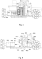
Fig. 3 is the side view of the device in a preferred configuration of the present invention; -
Fig. 4 shows a view of the device from a different side than infig. 3 in a preferred configuration of the present invention; -
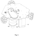
Fig. 5 is a view of the device from the underside in a preferred configuration of the present invention. - The mobile cutting and notching device consists of several assemblies attached to a
rigid base 900. The low-level controller unit 100 consists of a low-level controller 101 and a mountingbracket 102. The mountingbracket 102 is screwed to thebase 900. Mobility of the structure is ensured by threedrive wheel assemblies 200 arranged with radial axes, each at an angular distance of approximately 120°. The wheels are omni-directional 201, so-called Swedish wheels, facing outwards. The omni-directional wheels 201 consist of twowheel bodies 207 in which rollingelements 206 are embedded around the circumference, the rolling elements being in direct contact with the substrate on which the device platform moves. The omni-directional wheel 201 is connected to thedrive motor gearbox 205 by means of aconnector 203 joining the wheel to the shaft of thegearbox 205. Thegearbox 205 is integrated into thedrive motor 204 and is the component that connects to thegearbox assembly 202 with thedrive motor 204. Thedrive motors 204 are connected by wires to the low-level controller 101. - From a functional point of view, one of the most important components of the device is the cutting tool unit 600b which consists of a
cutting tool 602 in the form of a laser equipped with apressure nozzle 603. The laser is mounted on a height-adjustingrail 601 for thecutting tool 602, the rail being connected to thebase 900. Thecutting tool unit 600 is wired to a power source such as thebattery 400 and to the low-level controller 101, which is responsible for switching on and modulating the laser power to achieve cutting, partial cutting or engraving. In order to achieve a clean cut edge, a compression system is used, comprising acompressor 1002 connected via acompressed air hose 1001 to thelaser nozzle 603. This system is connected to thebattery 400 and the low-level controller 101, which turns it on during laser operation. In addition to compressed air blast, the second pneumatic system is annegative pressure unit 300, equipped with asuction turbine 302 mounted tightly in theexhaust extraction housing 303, tightly connected to thebase 900 above the exhaust filter withhousing 301. The purpose of thefilter 301, with its suitable properties, is to extract the exhaust fumes generated during laser cutting; it is pressed from below against the base by its exhaust filter housing, which is at the same time the suction duct leading to the laser nozzle from where the exhaust fumes/vapours are extracted during cutting, notching or engraving. - The device is equipped with a vision system that provides for a high degree of movement accuracy. The vision system consists of a
camera 500 mounted on thebase 900. The lens of thecamera 500 is positioned parallel to the sheet, at a distance that provides the greatest possible field of view. The camera is connected to a high-level controller 700, which evaluates the image and makes corrections to the movement so that the actual path of the device is a representation of the downloaded file. The operation of the machine according to the present invention by the operator is possible by means of a connection implemented through a network formed by the high-level controller 700, which is a minicomputer and is responsible for the software, communication with the low-level controller 101, processing the image from thecamera 500 and sending the appropriate commands to the controller to correct errors in the actual position of the device with respect to what it should be according to a pre-set shape, e.g. while cutting out a packaging template. The high-level controller 700 is connected to thebattery 400, thecamera 500 and the low-level controller 101. The operating time of the device is limited by thebattery 400. When the pattern takes longer to cut out, the device detects that thebattery 400 is low and then moves to the edge of the machined material to recharge, stopping the programme, but not interrupting it. Once thebattery 400 is recharged, the device resumes operation. - A mobile device as in embodiment 1, whereby it is provided with a
creasing unit 800, creasing a sheet of material along which the device according to the present invention moves. The working element is acreasing tip 802, shaped so as to achieve the right parameters at the creasing point. Different materials can be used at the end of the tip. It moves in an oscillatory forward and backward motion. It is rigidly connected to asleeve 815 supported by bearings, moving in the same manner as thecreasing tip 802 inside the lower sleeve bearing 817 in the lower part of thecreasing unit body 804 and theupper sleeve bearing 816. Thesleeve 815 is driven via a transversely mounted shaft with agear wheel 813 and eccentric 814. This part indirectly transmits the rotation from the creaseunit drive motor 812 via atoothed belt 818 wound onto agear wheel 813 on the shaft of the creaseunit drive motor 812. The creaseunit drive motor 812 is attached to thedrive motor mount 811 and is connected to thebattery 400 and the low-level controller 101. Thedrive motor mount 811 is the tensioning element for thetoothed belt 818 and is detachably connected to thecreasing unit body 804. The height of thecreasing unit 800 is set by means of a creaseunit height motor 810, the shaft axis of which is vertical and connected via acoupling 809 to anadjustment screw 803 rotating in a nut 808 - this kinematic pair holds the entire module at the set height. The creaseunit height motor 810 is attached to thebase 900. Thenut 808 is connected immovably to thecreasing unit holder 805 connecting the height adjustment elements, thebody 804 and the linear bearings of theholder 806 moving along thepins 807 fixed perpendicularly to the base 900 - thus thecreasing tip 802 only moves in one direction. To enable the machine to set the correct height for the creasing tool, alimit switch 801 has been installed, which, when pressed during the first lift from start-up, sends a signal to the low-level controller 101 about the starting position from which the height is measured during operation, based on the number of revolutions of the creaseunit height motor 810, which is responsible for adjusting the height. Thelimit switch 801 is wired to the low-level controller 101 and attached to thebase 900. -
- 100 -
- low-level controller unit
- 101 -
- low-level controller
- 102 -
- mounting bracket
- 200 -
- drive wheel assembly
- 201 -
- omni-directional wheel
- 202 -
- gearbox assembly
- 203 -
- connector
- 204 -
- drive motor
- 205 -
- drive motor gearbox
- 206 -
- rolling element
- 207 -
- wheel body
- 300 -
- negative pressure unit
- 301 -
- exhaust filter with housing
- 302 -
- suction turbine
- 303 -
- exhaust extraction housing
- 400 -
- battery
- 500 -
- camera
- 600 -
- cutting tool unit
- 601 -
- rail
- 602 -
- cutting tool
- 603 -
- pressure nozzle
- 700 -
- high-level controller
- 800 -
- creasing unit
- 801 -
- limit switch
- 802 -
- creasing tip
- 803 -
- adjustment screw
- 804 -
- creasing unit body
- 805 -
- creasing unit holder
- 806 -
- linear bearing
- 807 -
- feed pin
- 808 -
- nut
- 809 -
- coupling
- 810 -
- crease unit height motor
- 811 -
- motor mount
- 812 -
- crease unit drive motor
- 813 -
- gear wheel
- 814 -
- eccentric
- 815 -
- sleeve
- 816 -
- upper sleeve bearing
- 817 -
- lower sleeve bearing
- 818 -
- toothed belt
- 900 -
- base
- 1001 -
- compressed air hose
- 1002 -
- compressor
Claims (14)
- A mobile device with multifunctional tools, in the form of a self-moving platform providing movement of the device in the X and Y axes, comprising a rigid base with a drive unit and a tool assembly moved in the Z axis, characterised in that at least the following are attached to the rigid base (900):• drive wheel assemblies (200) arranged with their axes radially, each at essentially equal angular distance, with omni-directional wheels (201) attached by axle to the shaft of the drive motor (204), the common radius on which the omni-directional wheels are mounted being the distance from the centre of this circle to half the thickness of the wheels;• the low-level controller unit (100), consisting of at least the low-level controller (101);• the high-level controller unit (700), which is a microcomputer with software;• the cutting tool unit (600), comprising at least a cutting tool (602);• the power source (400);• the camera (500);whereby the drive wheel assemblies (200) and the cutting tool unit (600), are connected to the low-level controller unit (100), and the high-level controller unit (700), which are in principle connected to the power source (400) and to the camera (500).
- A mobile device according to claim 1, characterised in that a creasing unit (800) comprising at least a working element, preferably a creasing tip (802), and a crease unit drive motor (812) are mounted to a rigid base, the creasing unit (800) being connected to a low-level controller unit (100), and a high-level controller unit (700).
- A mobile device according to claim 2, characterised in that a creasing tip (802) is rigidly connected to a sleeve (815) supported by a lower bearing (817) in the lower part of the creasing unit body (804) and an upper bearing (816), the sleeve (815) being driven by a shaft with a gear wheel (813) and an eccentric (814) mounted transversely to it.
- A mobile device according to claim 3, characterised in that a crease unit drive motor (812) is attached to a drive motor mount (811) and is connected to a power source (400) and a low-level controller (101), the drive motor mount (811) being detachably connected to the creasing unit body (804).
- A mobile device according to claim 3, characterised in that it comprises a crease unit height motor (810) attached to a base (900), the vertical axis of the shaft of which is connected via a coupling (809) to an adjustment screw (803), rotating in a nut (808) fixedly connected to the creasing unit holder (805), connecting the creasing unit body (804) and the linear bearings of the holder (806) moving along pins (807) fixed perpendicularly to the base (900).
- A mobile device according to claim 5, characterised in that it comprises a limit switch (801), wired to a low-level controller (101) and attached to a base (900).
- A mobile device according to claim 2, characterised in that the working element of the creasing unit (800), is a creasing wheel.
- A device according to claim 1 or 2, characterised in that it comprises three drive wheel assemblies (200), spaced at an angular distance essentially equal to 120°.
- A mobile device according to claim 1 or 2, characterised in that the omni-directional wheels (201) comprise at least one wheel body (207) in which rolling elements (206) are circumferentially mounted and are connected to the drive motor gearbox (205) by means of a connector (203) joining the wheel to the shaft of the gearbox, which is integrated with the drive motor (204) and constitutes a component that connects the gearbox assembly (202) with the motor (204), which in turn is connected by wires to the low-level controller (101).
- A mobile device according to claim 1 or 2, characterised in that the cutting tool (602) is a laser equipped with a pressure nozzle (603) and mounted on a rail (601) connected to a base (900).
- A mobile device according to claim 10, characterised in that it comprises a compression system comprising a compressor (1002) connected by a compressed air hose (1001) to a laser nozzle (603).
- A mobile device according to claim 10, characterised in that it comprises an negative pressure unit (300), provided with a suction turbine (302) tightly mounted in an exhaust extraction housing (303), tightly connected to a base (900) above an exhaust filter with housing (301).
- A mobile device according to claim 1 or 2, characterised in that the drive motor (204), can be a stepper motor or other motor with an encoder suitable for monitoring the motor.
- A mobile device according to claim 1 or 2, characterised in that it is equipped with a print application unit comprising a pen, pencil, ballpoint pen or printer, or a labeller, and/or an adhesive applicator or other type of plastic extruder, and/or a water cutting, air cutting and/or milling unit.
Applications Claiming Priority (1)
| Application Number | Priority Date | Filing Date | Title |
|---|---|---|---|
| PL445033A PL445033A1 (en) | 2023-05-29 | 2023-05-29 | Mobile device with multifunctional tools |
Publications (2)
| Publication Number | Publication Date |
|---|---|
| EP4480689A2 true EP4480689A2 (en) | 2024-12-25 |
| EP4480689A3 EP4480689A3 (en) | 2025-03-05 |
Family
ID=91226777
Family Applications (1)
| Application Number | Title | Priority Date | Filing Date |
|---|---|---|---|
| EP24177177.3A Withdrawn EP4480689A3 (en) | 2023-05-29 | 2024-05-21 | Mobile device with multifunctional tools |
Country Status (2)
| Country | Link |
|---|---|
| EP (1) | EP4480689A3 (en) |
| PL (1) | PL445033A1 (en) |
Citations (6)
| Publication number | Priority date | Publication date | Assignee | Title |
|---|---|---|---|---|
| US20150003927A1 (en) | 2013-06-28 | 2015-01-01 | The Boeing Company | Magnet sensing hole driller and method therefor |
| CN206415771U (en) | 2017-01-16 | 2017-08-18 | 陈天润 | Desktop type laser engraving equipment |
| EP3403761A1 (en) | 2017-05-19 | 2018-11-21 | Springa S.R.L. | Tool system and method of operation of said tool system |
| CN211306315U (en) | 2019-08-07 | 2020-08-21 | 华北电力大学(保定) | CNC-based intelligent drawing robot |
| CN215615799U (en) | 2020-12-07 | 2022-01-25 | 北京信息科技大学 | A mobile laser engraving machine |
| CN215747068U (en) | 2021-07-28 | 2022-02-08 | 刘睿廷 | Portable laser engraving device |
Family Cites Families (6)
| Publication number | Priority date | Publication date | Assignee | Title |
|---|---|---|---|---|
| JP5761845B2 (en) * | 2011-03-02 | 2015-08-12 | スターテクノ株式会社 | Resin corrugated board ruled line forming device |
| US10245803B2 (en) * | 2013-03-13 | 2019-04-02 | Xerox Corporation | Apparatus, system and method for cutting and creasing media |
| CN106625665B (en) * | 2016-12-15 | 2019-03-12 | 北京卫星制造厂 | A kind of drilling milling machine device people's system of packaged type automatic addressing |
| WO2019210460A1 (en) * | 2018-05-02 | 2019-11-07 | Tti (Macao Commercial Offshore) Limited | Machine tool and related machine tool system |
| US20220055334A1 (en) * | 2019-04-29 | 2022-02-24 | Hewlett-Packard Development Company, L.P. | Media Creaser |
| RU2752349C1 (en) * | 2020-09-23 | 2021-07-26 | Дмитрий Сергеевич Кудияров | Automated moving machine |
-
2023
- 2023-05-29 PL PL445033A patent/PL445033A1/en unknown
-
2024
- 2024-05-21 EP EP24177177.3A patent/EP4480689A3/en not_active Withdrawn
Patent Citations (6)
| Publication number | Priority date | Publication date | Assignee | Title |
|---|---|---|---|---|
| US20150003927A1 (en) | 2013-06-28 | 2015-01-01 | The Boeing Company | Magnet sensing hole driller and method therefor |
| CN206415771U (en) | 2017-01-16 | 2017-08-18 | 陈天润 | Desktop type laser engraving equipment |
| EP3403761A1 (en) | 2017-05-19 | 2018-11-21 | Springa S.R.L. | Tool system and method of operation of said tool system |
| CN211306315U (en) | 2019-08-07 | 2020-08-21 | 华北电力大学(保定) | CNC-based intelligent drawing robot |
| CN215615799U (en) | 2020-12-07 | 2022-01-25 | 北京信息科技大学 | A mobile laser engraving machine |
| CN215747068U (en) | 2021-07-28 | 2022-02-08 | 刘睿廷 | Portable laser engraving device |
Also Published As
| Publication number | Publication date |
|---|---|
| EP4480689A3 (en) | 2025-03-05 |
| PL445033A1 (en) | 2024-12-02 |
Similar Documents
| Publication | Publication Date | Title |
|---|---|---|
| CN1520972A (en) | Method for controlling slitter-scorer apparatus | |
| CN104128958A (en) | Automatic feeding mechanical arm for punch press | |
| CN110395896B (en) | Photoelectric glass cutting machine | |
| CN110449634A (en) | A kind of drilling machine of numerical control finishing | |
| CN105598808A (en) | Automatic polishing system and method | |
| CN103372875B (en) | Cutting plotter with blade clearance groove | |
| CN201211629Y (en) | High-precision, fully automatic rubber roller grinding machine | |
| IT201900016778A1 (en) | LOCALIZATION SYSTEM FOR MACHINE TOOL AND LOCALIZATION METHOD REALIZED BY SAID SYSTEM | |
| CN103894678B (en) | A kind of ream ellipse nest device | |
| KR20120046481A (en) | Punching device for punching papers using supersonic waves and method of punching using the same | |
| JP2008307684A (en) | Glass plate processing equipment | |
| CN206065938U (en) | The automatic drilling and milling machine of plane | |
| CN203920045U (en) | Rotation three-dimensional regulation marking device | |
| CN201125212Y (en) | Liquid crystal glass automatic breaking machine | |
| CN105478916A (en) | Five-axis cutting machine | |
| CN206812133U (en) | A kind of cutting machine for being conveniently replaceable cutter head | |
| RU2752349C1 (en) | Automated moving machine | |
| CN102059724B (en) | Intelligentized woodworking curve sawing machine | |
| JP4211536B2 (en) | Glass plate processing equipment | |
| CN210617407U (en) | Cutting and edge pressing machine for packing box | |
| CN211639250U (en) | Multi-station tool passivation machine | |
| CN118435505B (en) | Method for machining a flat object using a flat drive system | |
| CN205394660U (en) | Accurate paper cutting device of dust protected | |
| US6908267B1 (en) | Variable radii cutter | |
| CN108214123A (en) | A kind of 5-shaft linkage numerical control grinding attachment for being ground nonstandard cutter and blade |
Legal Events
| Date | Code | Title | Description |
|---|---|---|---|
| PUAI | Public reference made under article 153(3) epc to a published international application that has entered the european phase |
Free format text: ORIGINAL CODE: 0009012 |
|
| STAA | Information on the status of an ep patent application or granted ep patent |
Free format text: STATUS: THE APPLICATION HAS BEEN PUBLISHED |
|
| AK | Designated contracting states |
Kind code of ref document: A2 Designated state(s): AL AT BE BG CH CY CZ DE DK EE ES FI FR GB GR HR HU IE IS IT LI LT LU LV MC ME MK MT NL NO PL PT RO RS SE SI SK SM TR |
|
| PUAL | Search report despatched |
Free format text: ORIGINAL CODE: 0009013 |
|
| AK | Designated contracting states |
Kind code of ref document: A3 Designated state(s): AL AT BE BG CH CY CZ DE DK EE ES FI FR GB GR HR HU IE IS IT LI LT LU LV MC ME MK MT NL NO PL PT RO RS SE SI SK SM TR |
|
| RIC1 | Information provided on ipc code assigned before grant |
Ipc: B31B 100/00 20170101ALN20250128BHEP Ipc: B23K 26/08 20140101ALI20250128BHEP Ipc: B23Q 9/00 20060101ALI20250128BHEP Ipc: B60K 7/00 20060101ALI20250128BHEP Ipc: B31F 1/10 20060101ALI20250128BHEP Ipc: B31F 1/08 20060101ALI20250128BHEP Ipc: B31B 50/88 20170101ALI20250128BHEP Ipc: B31B 50/25 20170101ALI20250128BHEP Ipc: B31B 50/00 20170101ALI20250128BHEP Ipc: B31B 50/20 20170101AFI20250128BHEP |
|
| STAA | Information on the status of an ep patent application or granted ep patent |
Free format text: STATUS: THE APPLICATION IS DEEMED TO BE WITHDRAWN |
|
| 18D | Application deemed to be withdrawn |
Effective date: 20250906 |