EP4480663A1 - Writing implement part, method for manufacturing writing implement part, and writing implement - Google Patents
Writing implement part, method for manufacturing writing implement part, and writing implement Download PDFInfo
- Publication number
- EP4480663A1 EP4480663A1 EP23854924.0A EP23854924A EP4480663A1 EP 4480663 A1 EP4480663 A1 EP 4480663A1 EP 23854924 A EP23854924 A EP 23854924A EP 4480663 A1 EP4480663 A1 EP 4480663A1
- Authority
- EP
- European Patent Office
- Prior art keywords
- writing instrument
- instrument part
- mold
- core pin
- manufacturing
- Prior art date
- Legal status (The legal status is an assumption and is not a legal conclusion. Google has not performed a legal analysis and makes no representation as to the accuracy of the status listed.)
- Pending
Links
Images




Classifications
-
- B—PERFORMING OPERATIONS; TRANSPORTING
- B43—WRITING OR DRAWING IMPLEMENTS; BUREAU ACCESSORIES
- B43K—IMPLEMENTS FOR WRITING OR DRAWING
- B43K5/00—Pens with ink reservoirs in holders, e.g. fountain-pens
- B43K5/005—Pen barrels
-
- B—PERFORMING OPERATIONS; TRANSPORTING
- B43—WRITING OR DRAWING IMPLEMENTS; BUREAU ACCESSORIES
- B43K—IMPLEMENTS FOR WRITING OR DRAWING
- B43K7/00—Ball-point pens
- B43K7/005—Pen barrels
-
- B—PERFORMING OPERATIONS; TRANSPORTING
- B27—WORKING OR PRESERVING WOOD OR SIMILAR MATERIAL; NAILING OR STAPLING MACHINES IN GENERAL
- B27N—MANUFACTURE BY DRY PROCESSES OF ARTICLES, WITH OR WITHOUT ORGANIC BINDING AGENTS, MADE FROM PARTICLES OR FIBRES CONSISTING OF WOOD OR OTHER LIGNOCELLULOSIC OR LIKE ORGANIC MATERIAL
- B27N5/00—Manufacture of non-flat articles
-
- B—PERFORMING OPERATIONS; TRANSPORTING
- B29—WORKING OF PLASTICS; WORKING OF SUBSTANCES IN A PLASTIC STATE IN GENERAL
- B29C—SHAPING OR JOINING OF PLASTICS; SHAPING OF MATERIAL IN A PLASTIC STATE, NOT OTHERWISE PROVIDED FOR; AFTER-TREATMENT OF THE SHAPED PRODUCTS, e.g. REPAIRING
- B29C45/00—Injection moulding, i.e. forcing the required volume of moulding material through a nozzle into a closed mould; Apparatus therefor
- B29C45/0001—Injection moulding, i.e. forcing the required volume of moulding material through a nozzle into a closed mould; Apparatus therefor characterised by the choice of material
-
- B—PERFORMING OPERATIONS; TRANSPORTING
- B29—WORKING OF PLASTICS; WORKING OF SUBSTANCES IN A PLASTIC STATE IN GENERAL
- B29C—SHAPING OR JOINING OF PLASTICS; SHAPING OF MATERIAL IN A PLASTIC STATE, NOT OTHERWISE PROVIDED FOR; AFTER-TREATMENT OF THE SHAPED PRODUCTS, e.g. REPAIRING
- B29C45/00—Injection moulding, i.e. forcing the required volume of moulding material through a nozzle into a closed mould; Apparatus therefor
- B29C45/14—Injection moulding, i.e. forcing the required volume of moulding material through a nozzle into a closed mould; Apparatus therefor incorporating preformed parts or layers, e.g. injection moulding around inserts or for coating articles
- B29C45/14598—Coating tubular articles
- B29C45/14622—Lining the inner or outer surface of tubular articles
-
- B—PERFORMING OPERATIONS; TRANSPORTING
- B43—WRITING OR DRAWING IMPLEMENTS; BUREAU ACCESSORIES
- B43K—IMPLEMENTS FOR WRITING OR DRAWING
- B43K15/00—Assembling, finishing, or repairing pens
-
- B—PERFORMING OPERATIONS; TRANSPORTING
- B43—WRITING OR DRAWING IMPLEMENTS; BUREAU ACCESSORIES
- B43K—IMPLEMENTS FOR WRITING OR DRAWING
- B43K7/00—Ball-point pens
- B43K7/02—Ink reservoirs; Ink cartridges
-
- B—PERFORMING OPERATIONS; TRANSPORTING
- B43—WRITING OR DRAWING IMPLEMENTS; BUREAU ACCESSORIES
- B43K—IMPLEMENTS FOR WRITING OR DRAWING
- B43K8/00—Pens with writing-points other than nibs or balls
- B43K8/003—Pen barrels
-
- B—PERFORMING OPERATIONS; TRANSPORTING
- B29—WORKING OF PLASTICS; WORKING OF SUBSTANCES IN A PLASTIC STATE IN GENERAL
- B29K—INDEXING SCHEME ASSOCIATED WITH SUBCLASSES B29B, B29C OR B29D, RELATING TO MOULDING MATERIALS OR TO MATERIALS FOR MOULDS, REINFORCEMENTS, FILLERS OR PREFORMED PARTS, e.g. INSERTS
- B29K2511/00—Use of natural products or their composites, not provided for in groups B29K2401/00 - B29K2509/00, as filler
- B29K2511/14—Wood, e.g. woodboard or fibreboard
-
- B—PERFORMING OPERATIONS; TRANSPORTING
- B43—WRITING OR DRAWING IMPLEMENTS; BUREAU ACCESSORIES
- B43K—IMPLEMENTS FOR WRITING OR DRAWING
- B43K19/00—Non-propelling pencils; Styles; Crayons; Chalks
- B43K19/14—Sheathings
Definitions
- the present invention relates to writing instrument parts, a method for making parts for writing instruments using wood flour as a natural material, and a writing instrument.
- Wood flour has been conventionally used as material for a barrel member, a writing instrument part, which constitutes a writing instrument. (See Patent Literature 1 to 5)
- writing instrument parts are often made by injection molding because complicated features can be molded in large quantities.
- Patent Literature 6 discloses a resin-molded part forming the outer shape of a writing instrument as an example of a writing instrument part made by injection molding.
- a mold in which a core pin forming the inner surface of a barrel member is set, and a molten resin material is injected from the gate, which is a resin injection hole provided on the mold, to fill the space in the mold with the resin material. After the filled resin material is cured, the core pin is removed and the barrel member is obtained by opening the mold.
- writing instrument parts are commonly made by injection molding, and then, various synthetic resin materials can be used such as polypropylene, polycarbonate, and ABS resin.
- a core pin is first set in a mold for injection molding to form a space for forming a barrel member, and the above wooden barrel material is injected into the space in the mold. Then, the mold is removed and a molded article in which the wooden barrel material and the core pin are integrated is produced by insert molding. Then, in a subsequent process, the core pin is pulled out of the molded article and released from the mold to obtain a barrel member with the desired shape.
- the molded article needs to be heated to cure the wooden barrel material part, but the releasability of the core pin deteriorates due to the heating, and the inner surface becomes distorted when the core pin is forcibly pulled out.
- the present invention was made in view of the above-mentioned problems, and the purpose of the present invention is to provide a writing instrument part in which the releasability of the core pin is improved, a method of manufacturing the writing instrument part, and a writing instrument including the writing instrument part, with respect to the writing instrument part produced by releasing the core pin from the molded article in which the wooden barrel material and the core pin are integrally molded by insert molding.
- the writing instrument part according to the present invention is characterized in that the part in which the wooden barrel material and the core pin in which a paper straw is inserted are integrally molded by insert molding in which the wooden barrel material composed of wood flour and a binder of water-soluble resin is injected into the mold and a two-layer structure having a paper straw layer on the inner layer and a wooden barrel layer on the outer layer is formed by releasing the core pin.
- the core pin is made slippery by the effect of the paper straw layer, and the releasability when the core pin is pulled out can be greatly improved.
- the wood flour be sawdust of coniferous trees such as cedar, cypress, incense cedar, or red cedar, or of broadleaf trees such as beech, sawtooth oak, or oak, or bamboo powder, and it is desirable that the binder be cellulose or a cellulose derivative; and it is further desirable that the paper straws be tubular, made by agglutinating plant fibers or other fibers.
- a space having the shape of the writing instrument part is first formed in a mold by setting the core pin inserted with a paper straw, and a wooden barrel material composed of wood flour and binder of water-soluble resin is injected into the space through a mold spout provided on the mold.
- the mold is removed, and the first molded article is produced in a state where the wooden barrel material and the core pin are integrally formed by insert molding.
- a writing instrument part having a two-layer structure with a straw layer on the inner layer and wooden barrel layer on the outer layer is obtained.
- a gate connected to the mold spout is formed as a storage space for the wooden barrel material, and the gate is circumferentially provided on an outer surface of the core pin that is formed between the mold spout and the above space.
- the core pin is released from the second molded article and the excess portion molded into the shape of the gate is cut off to obtain the writing instrument parts with the two-layer structure described above.
- the heating to the first molded article is carried out under the condition of 150 °C for one hour and the wood flour is sawdust from coniferous trees such as cedar, cypress, incense cedar, or red cedar, or from broadleaf trees such as beech, sawtooth oak, or oak, or bamboo powder, and the binder is desirably cellulose or a cellulose derivative; and it being further desirable that the paper straws be tubular, made by agglutinating plant fibers or other fibers.
- Writing instruments according to the present invention include the writing instrument parts according to the present invention described above. Further, the writing instruments according to the present invention include the writing instrument parts manufactured by the above-described manufacturing method of the writing instrument parts according to the present invention described above.
- the present invention makes it possible to provide a writing instrument part that improves the releasability of the core pin.
- a writing instrument part according to the present invention a method of manufacturing the writing instrument part, and a writing instrument will be described in detail below with reference to the drawings.
- the present invention is not limited to these embodiments.
- components that can be described similarly in the description and drawings of the present invention will be referred to by the same reference signs, and duplication of description will be omitted.
- Figs. 1A to 1C are views illustrating an example of the configuration of a writing instrument according to the present embodiment
- Fig. 1A is a front view of the external appearance of the writing instrument
- 1B is a cross-sectional view of the writing instrument
- 1C is a perspective view of the writing instrument.
- the configuration of a ballpoint pen is described as an example of a writing instrument.
- a ballpoint pen 1 (writing instrument 1) according to the present embodiment has a barrel 2 having an approximately cylindrical shape and accommodates a refill 3 in the barrel 2.
- the barrel 2 is composed of a wooden barrel tip 4, a front barrel 5, and a rear barrel 6 in the order described from the tip end from which a ballpoint pen tip 3a protrudes which is part of the refill 3.
- the wooden barrel tip 4, the front barrel 5, and the rear barrel 6 are formed as writing instrument parts (barrel members) of the present embodiment by injection molding in which the wooden barrel material made of wood flour, a natural material, as a base material (main component) is injected into a predetermined mold.
- the rear end of the wooden barrel tip 4 and the front end of the front barrel 5, and the rear end of the front barrel 5 and the front end of the rear barrel 6 are detachably fitted, respectively.
- the refill 3 to be accommodated in the barrel 2 is provided with a long thin cylindrical ink reservoir 3b storing ink, a joint member 3c attached to the tip end of the ink reservoir 3b, and a ballpoint pen tip 3a attached to the tip end of the joint member 3c.
- the ballpoint pen 1 has a structure in which the upper surface 4a, the periphery of the opening, of the rear end of the wooden barrel tip 4 and the locking member 5a provided on the inner periphery near the tip end of the front barrel 5 sandwich the flange portion 3d, or the flange portion 3d provided on the joint member 3c, provided on the outer periphery of the refill 3, for receiving the writing pressure.
- Figs.2A to 2F are views illustrating an example of the configuration of the front barrel, which is one of the writing instrument parts according to the present embodiment;
- Fig. 2A is a front perspective view
- Fig. 2B is a rear perspective view
- Fig. 2C is a bottom view
- Fig. 2D is a plan view
- Fig. 2E is a front view
- Fig. 2F is a front cross-sectional view, respectively.
- the front barrel 5 has a penetrating hole 5b provided so that the ink reservoir 3b of the refill 3 can be inserted therethrough, and has a configuration in which a connecting portion 5c formed into an approximately cylindrical shape as a rear end portion to which the rear barrel 6 is connected by press-fitting, a cylindrical portion 5d formed into an approximately cylindrical shape having a larger outer diameter than the connecting portion 5c, and a tapered portion 5e tapered toward the tip end having a tip end opening (the tip end of the penetrating hole 5b) to be press-fitted to the wooden barrel tip 4, are connected.
- the front barrel 5 is provided with an inner layer 5f of the paper straw (the paper straw layer 5f) in close contact with the wall surface of the penetrating hole 5b. That is, the front barrel 5 forms a two-layer structure together with the wooden barrel layer constituting the outer layer (the layer composed of the connecting portion 5c, the cylindrical portion 5d and the tapered portion 5e).
- the paper straw layer 5f is provided for the purpose of improving the releasability of the core pin described later.
- the material of the paper straw may be any tubular material made by agglomeration of plant fibers or other fibers, as long as it does not stick to the core pins when molded below 150°C and integrates (including tightening and bonding by shrinkage) with the wood barrel material after drying.
- the wall thickness of the paper straw is preferably 0.2 mm to 2.0 mm.
- the wooden barrel material is composed of wood flour as a natural material and a water-soluble resin as a binder, for example, and the compounding ratio of the wood flour and the binder is preferably 9:1 to 6:4, and further preferably 9:1 to 7:3.
- Sawdust from coniferous trees such as cedar, cypress, or pine tree, or from deciduous trees such as beech, oak, or sawtooth oak, or cork or bamboo powder can be used as wood flour, preferably with a particle size of less than 3 mm to obtain better surface properties.
- the particle size of the wood flour is preferably 0.1 mm or more to prevent it from distorting during drying.
- the particle size is less than 0.1 mm, it is undesirable because the pathways for moisture are likely to be closed during shrinkage during drying, and the wooden barrel material may be distorted so that a proper shape cannot be obtained.
- water-soluble or hydrophilic substances are preferable, such as cellulose, cellulose derivatives (carboxymethyl cellulose, ammonium carboxymethyl cellulose, sodium carboxymethyl cellulose, methylcellulose), sodium alginate, polyvinyl alcohol, polyoxyethylene, polyacrylamide, copolymerized maleic acid resin.
- a method of manufacturing a writing instrument part according to the present embodiment will be described in detail.
- a method of manufacturing a writing instrument part a method of manufacturing a front barrel 5 will be described, and a wooden barrel tip 4 and a rear barrel 6 can be similarly manufactured.
- Fig. 3 is a view illustrating an example of a member for manufacturing which is to be used in the method of manufacturing the writing instrument part according to the present embodiment.
- Fig. 4 is an exploded block structural view of a manufacturing member to be used in the method of manufacturing the writing instrument part according to the present embodiment and a manufactured writing instrument part.
- the front barrel 5 is manufactured by using a mold 11 formed so as to sandwich a first mold 11a and a second mold 11b and a core pin 14 to which a stripper washer 12 and a paper straw 13 are inserted at a predetermined position.
- the core pin 14 see Fig.
- the front barrel 5 is formed by injecting the wooden barrel material described above through the mold spout 15 provided in the mold 11, i.e., by injection molding.
- Figs. 5A to 11F are views illustrating an example of the method of manufacturing a writing instrument part according to the present embodiment.
- the method of manufacturing the front barrel 5 will be more specifically described below with reference to Figs. 5a to 11F .
- Figs. 5A and 5B are cross-sectional views of the mold 11 illustrating a state in which the core pin 14, including the stripper washer 12 and the paper straw 13, is placed in the mold 11;
- Fig. 5A is a front cross-sectional view viewed from the front side of the sandwiching surface, the first mold 11a and the second mold 11b, of the mold 11 and
- Fig. 5B is a side cross-sectional view viewed from the side of the mold 11.
- the space 16 having the shape of the front barrel 5 (the wooden barrel tip 4, the front barrel 5, the rear barrel 6) is formed by setting the core pin 14 integrated with the stripper washer 12 and the paper straw 13 in the mold 11.
- a gate 15a connected to a mold spout 15 is formed in the mold 11 as a storage space for wooden barrel material.
- the gate 15a is circumferentially provided on the outer periphery of the core pin 14 between the mold spout 15 and the space 16 so that the wooden barrel material injected through the mold spout 15 is uniformly distributed in the space 16 (see Fig. 5A and 5B ).
- Figs. 6A and 6B are cross-sectional views of the mold 11 in a state in which the wooden barrel material is injected into the gate 15a; Fig. 6A is a front cross-sectional view and Fig. 6B is a side cross-sectional view.
- Figs. 7A and 7B are cross-sectional views of the mold 11 in a state in which the mold is completely filled with the wooden barrel material; Fig. 7a is a front cross-sectional view and Fig. 7B is a side cross-sectional view.
- Figs. 8A and 8B are cross-sectional views illustrating an example of the molded article 21; Fig. 8A is a front cross-sectional view and Fig. 8B is a side cross-sectional view.
- the molded article 21 is then heated in a dryer (not shown) at 150°C for one hour to harden the wooden barrel material portion shown in Figs. 8A and 8B .
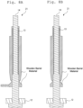
- the core pin 14 is pulled out of the hardened wooden barrel material portion (mold releasing) by pushing in the stripper washer 12 (see Figs. 9A and 9B ), and a molded article 21'' is obtained in a state in which the front barrel 5 and the excess portion 22 formed in the shape of the gate 15a are integrated (see Figs. 10A and 10B ).
- Figs. 9A and 9B are cross-sectional views illustrating the molded article 21' in a state in which the stripper washer 12 is pushed in; Fig. 9A is a front cross-sectional view and Fig. 9B is a side cross-sectional view.
- Figs 10A and 10B are cross-sectional views of an example of the molded article 21"; Fig. 10A is a front cross-sectional view and Fig. 10b is a side cross-sectional view.
- Figs. 11A to 11F are views illustrating the final process; Fig. 11A is a front perspective view, Fig. 11B is a rear perspective view, Fig. 11C is a front view, Fig. 11D is a front cross-sectional view, Fig. 11E is a side view, and Fig. 11F is a side cross-sectional view.
- the writing instrument parts of this embodiment are manufactured by insert molding, in which a wooden barrel material composed of wood flour, a natural material, and a binder, a water-soluble resin, is injected into the mold 11 to integrate the wooden barrel material and the core pin 14 into which the paper straw 13 is inserted, and then the core pin 14 is released, thereby forming a two-layer structure having a paper straw layer 5f on the inner layer and a wooden barrel layer (layers of connecting portion 5c, cylindrical portion 5d, and tapered portion 5e) on the outer layer.
- a wooden barrel material composed of wood flour, a natural material, and a binder, a water-soluble resin
- the space 16 having the shape of the writing instrument part is first formed in the mold 11 by setting the core pin 14 to which the paper straw 13 is attached. Then, the wooden barrel material composed of wood flour and a binder which is a water-soluble resin is injected into the space 16 through the mold spout 15 provided on the mold 11. After the injection is completed, the mold 11 is removed and the molded article 21 is manufactured in the state in which the wooden barrel material and the core pin 14 are integrated by insert molding.
- the writing instrument part having the two-layer structure with the paper straw layer 5f on the inner layer thereof and the wooden barrel layer on the outer layer thereof is obtained.
- the core pin 14 is made slippery by the paper straw layer 5f, which is the paper straw 13, and the releasability when the core pin 14 is pulled out can be greatly improved.
- the writing instrument part and the method of manufacturing the writing instrument part according to the present invention are useful as one of the endeavors to global environmental problems such as reducing the use of plastics.
Landscapes
- Engineering & Computer Science (AREA)
- Mechanical Engineering (AREA)
- Manufacturing & Machinery (AREA)
- Life Sciences & Earth Sciences (AREA)
- Wood Science & Technology (AREA)
- Forests & Forestry (AREA)
- Injection Moulding Of Plastics Or The Like (AREA)
- Pens And Brushes (AREA)
Abstract
Description
- The present invention relates to writing instrument parts, a method for making parts for writing instruments using wood flour as a natural material, and a writing instrument.
- Wood flour has been conventionally used as material for a barrel member, a writing instrument part, which constitutes a writing instrument. (See
Patent Literature 1 to 5) - Meanwhile, writing instrument parts are often made by injection molding because complicated features can be molded in large quantities.
- For example,
Patent Literature 6 discloses a resin-molded part forming the outer shape of a writing instrument as an example of a writing instrument part made by injection molding. - Specifically, in the injection molding process described in
Patent Literature 6, a mold is used in which a core pin forming the inner surface of a barrel member is set, and a molten resin material is injected from the gate, which is a resin injection hole provided on the mold, to fill the space in the mold with the resin material. After the filled resin material is cured, the core pin is removed and the barrel member is obtained by opening the mold. -
- PTL 1:
JP-T-2011-527953 - PTL 2:
JA-A-2006-181726 - PTL 3:
JP-A-2012-20568 - PTL 4:
JP-UM-A-63-882 - PTL 5:
JP2001-54997 - PTL 6:
JP-A-2012-228790 - As described above, writing instrument parts are commonly made by injection molding, and then, various synthetic resin materials can be used such as polypropylene, polycarbonate, and ABS resin.
- Meanwhile, when writing instrument parts are molded by injection molding using a wooden barrel member with wood flour as the base (main) material instead of using the above-described synthetic resin material, the following problems may arise.
- For example, in the manufacturing process of a barrel member (e.g., a front barrel), a core pin is first set in a mold for injection molding to form a space for forming a barrel member, and the above wooden barrel material is injected into the space in the mold. Then, the mold is removed and a molded article in which the wooden barrel material and the core pin are integrated is produced by insert molding. Then, in a subsequent process, the core pin is pulled out of the molded article and released from the mold to obtain a barrel member with the desired shape. However, when forming a barrel member by this method, the molded article needs to be heated to cure the wooden barrel material part, but the releasability of the core pin deteriorates due to the heating, and the inner surface becomes distorted when the core pin is forcibly pulled out.
- The present invention was made in view of the above-mentioned problems, and the purpose of the present invention is to provide a writing instrument part in which the releasability of the core pin is improved, a method of manufacturing the writing instrument part, and a writing instrument including the writing instrument part, with respect to the writing instrument part produced by releasing the core pin from the molded article in which the wooden barrel material and the core pin are integrally molded by insert molding.
- The writing instrument part according to the present invention is characterized in that the part in which the wooden barrel material and the core pin in which a paper straw is inserted are integrally molded by insert molding in which the wooden barrel material composed of wood flour and a binder of water-soluble resin is injected into the mold and a two-layer structure having a paper straw layer on the inner layer and a wooden barrel layer on the outer layer is formed by releasing the core pin.
- Thus, the core pin is made slippery by the effect of the paper straw layer, and the releasability when the core pin is pulled out can be greatly improved.
- In the writing instrument parts according to the present invention, it is desirable that the wood flour be sawdust of coniferous trees such as cedar, cypress, incense cedar, or red cedar, or of broadleaf trees such as beech, sawtooth oak, or oak, or bamboo powder, and it is desirable that the binder be cellulose or a cellulose derivative; and it is further desirable that the paper straws be tubular, made by agglutinating plant fibers or other fibers.
- In the method of manufacturing the writing instrument parts according to the present invention, a space having the shape of the writing instrument part is first formed in a mold by setting the core pin inserted with a paper straw, and a wooden barrel material composed of wood flour and binder of water-soluble resin is injected into the space through a mold spout provided on the mold. After injection, the mold is removed, and the first molded article is produced in a state where the wooden barrel material and the core pin are integrally formed by insert molding. By heating the first molded article to harden and releasing the core pin from the second molded article, which is the heated first molded article, a writing instrument part having a two-layer structure with a straw layer on the inner layer and wooden barrel layer on the outer layer is obtained. This manufacturing method allows the core pin to slide easily and greatly improves the releasability due to the effect of the paper straw layer when the core pin is pulled out.
- In the manufacturing method of a writing instrument part according to the present invention, on the mold, a gate connected to the mold spout is formed as a storage space for the wooden barrel material, and the gate is circumferentially provided on an outer surface of the core pin that is formed between the mold spout and the above space. The core pin is released from the second molded article and the excess portion molded into the shape of the gate is cut off to obtain the writing instrument parts with the two-layer structure described above.
- In the manufacturing method of a writing instrument part according to the present invention, it is desirable that the heating to the first molded article is carried out under the condition of 150 °C for one hour and the wood flour is sawdust from coniferous trees such as cedar, cypress, incense cedar, or red cedar, or from broadleaf trees such as beech, sawtooth oak, or oak, or bamboo powder, and the binder is desirably cellulose or a cellulose derivative; and it being further desirable that the paper straws be tubular, made by agglutinating plant fibers or other fibers.
- Writing instruments according to the present invention include the writing instrument parts according to the present invention described above. Further, the writing instruments according to the present invention include the writing instrument parts manufactured by the above-described manufacturing method of the writing instrument parts according to the present invention described above.
- The present invention makes it possible to provide a writing instrument part that improves the releasability of the core pin.
-
-
Figs. 1A to 1C are views illustrating an example of the configuration of a writing instrument according to the present invention. -
Figs. 2A to 2F are views illustrating an example of the configuration of a front barrel which is one of the writing instrument parts according to the present invention. -
Fig. 3 is a view illustrating an example of a member for manufacturing which is to be used in the method of manufacturing the writing instrument part according to the present invention. -
Fig. 4 is an exploded block structural view of a manufacturing member to be used in the method of manufacturing the writing instrument part according to the present invention and a manufactured writing instrument part. -
Figs. 5A and 5B are views illustrating an example of a method of manufacturing the writing instrument part according to the present invention. -
Figs. 6A and 6B are views illustrating an example of a method of manufacturing the writing instrument part according to the present invention. -
Figs. 7A and 7B are views illustrating an example of a method of manufacturing the writing instrument part according to the present invention. -
Figs. 8A and 8B are views illustrating an example of a method of manufacturing the writing instrument part according to the present invention. -
Figs. 9A and 9B are views illustrating an example of a method of manufacturing the writing instrument part according to the present invention. -
Figs. 10A and 10B are views illustrating an example of a method of manufacturing the writing instrument part according to the present invention. -
Figs. 11A to 11F are views illustrating an example of a method of manufacturing the writing instrument part according to the present invention. - A writing instrument part according to the present invention, a method of manufacturing the writing instrument part, and a writing instrument will be described in detail below with reference to the drawings. However, the present invention is not limited to these embodiments. In some cases, components that can be described similarly in the description and drawings of the present invention will be referred to by the same reference signs, and duplication of description will be omitted.
-
Figs. 1A to 1C are views illustrating an example of the configuration of a writing instrument according to the present embodiment, andFig. 1A is a front view of the external appearance of the writing instrument, 1B is a cross-sectional view of the writing instrument, and 1C is a perspective view of the writing instrument. In the present embodiment, the configuration of a ballpoint pen is described as an example of a writing instrument. - A ballpoint pen 1 (writing instrument 1) according to the present embodiment has a
barrel 2 having an approximately cylindrical shape and accommodates arefill 3 in thebarrel 2. Thebarrel 2 is composed of awooden barrel tip 4, afront barrel 5, and arear barrel 6 in the order described from the tip end from which aballpoint pen tip 3a protrudes which is part of therefill 3. Thewooden barrel tip 4, thefront barrel 5, and therear barrel 6 are formed as writing instrument parts (barrel members) of the present embodiment by injection molding in which the wooden barrel material made of wood flour, a natural material, as a base material (main component) is injected into a predetermined mold. As for thebarrel 2, the rear end of thewooden barrel tip 4 and the front end of thefront barrel 5, and the rear end of thefront barrel 5 and the front end of therear barrel 6 are detachably fitted, respectively. - As described above, the
refill 3 to be accommodated in thebarrel 2 is provided with a long thincylindrical ink reservoir 3b storing ink, ajoint member 3c attached to the tip end of theink reservoir 3b, and aballpoint pen tip 3a attached to the tip end of thejoint member 3c. - In
Fig. 1B , theballpoint pen 1 has a structure in which theupper surface 4a, the periphery of the opening, of the rear end of thewooden barrel tip 4 and the lockingmember 5a provided on the inner periphery near the tip end of thefront barrel 5 sandwich theflange portion 3d, or theflange portion 3d provided on thejoint member 3c, provided on the outer periphery of therefill 3, for receiving the writing pressure. -
Figs.2A to 2F are views illustrating an example of the configuration of the front barrel, which is one of the writing instrument parts according to the present embodiment;Fig. 2A is a front perspective view,Fig. 2B is a rear perspective view,Fig. 2C is a bottom view,Fig. 2D is a plan view,Fig. 2E is a front view, andFig. 2F is a front cross-sectional view, respectively. - As shown in
Figs. 2 A to 2F , thefront barrel 5 has a penetratinghole 5b provided so that theink reservoir 3b of therefill 3 can be inserted therethrough, and has a configuration in which a connectingportion 5c formed into an approximately cylindrical shape as a rear end portion to which therear barrel 6 is connected by press-fitting, acylindrical portion 5d formed into an approximately cylindrical shape having a larger outer diameter than the connectingportion 5c, and a taperedportion 5e tapered toward the tip end having a tip end opening (the tip end of the penetratinghole 5b) to be press-fitted to thewooden barrel tip 4, are connected. - In addition, the
front barrel 5 is provided with aninner layer 5f of the paper straw (thepaper straw layer 5f) in close contact with the wall surface of the penetratinghole 5b. That is, thefront barrel 5 forms a two-layer structure together with the wooden barrel layer constituting the outer layer (the layer composed of the connectingportion 5c, thecylindrical portion 5d and the taperedportion 5e). Thepaper straw layer 5f is provided for the purpose of improving the releasability of the core pin described later. The material of the paper straw may be any tubular material made by agglomeration of plant fibers or other fibers, as long as it does not stick to the core pins when molded below 150°C and integrates (including tightening and bonding by shrinkage) with the wood barrel material after drying. The wall thickness of the paper straw is preferably 0.2 mm to 2.0 mm. - For writing instrument parts according to the present embodiment, the preferred wooden barrel material will be described.
- The wooden barrel material is composed of wood flour as a natural material and a water-soluble resin as a binder, for example, and the compounding ratio of the wood flour and the binder is preferably 9:1 to 6:4, and further preferably 9:1 to 7:3.
- Sawdust from coniferous trees such as cedar, cypress, or pine tree, or from deciduous trees such as beech, oak, or sawtooth oak, or cork or bamboo powder can be used as wood flour, preferably with a particle size of less than 3 mm to obtain better surface properties. When the particle size is 3mm or more, it is undesirable because there may be irregularities on the surface of parts due to particles. Furthermore, the particle size of the wood flour is preferably 0.1 mm or more to prevent it from distorting during drying. When the particle size is less than 0.1 mm, it is undesirable because the pathways for moisture are likely to be closed during shrinkage during drying, and the wooden barrel material may be distorted so that a proper shape cannot be obtained.
- As binders, water-soluble or hydrophilic substances are preferable, such as cellulose, cellulose derivatives (carboxymethyl cellulose, ammonium carboxymethyl cellulose, sodium carboxymethyl cellulose, methylcellulose), sodium alginate, polyvinyl alcohol, polyoxyethylene, polyacrylamide, copolymerized maleic acid resin.
- Next, a method of manufacturing a writing instrument part according to the present embodiment will be described in detail. In the present embodiment, as an example of a method of manufacturing a writing instrument part, a method of manufacturing a
front barrel 5 will be described, and awooden barrel tip 4 and arear barrel 6 can be similarly manufactured. -
Fig. 3 is a view illustrating an example of a member for manufacturing which is to be used in the method of manufacturing the writing instrument part according to the present embodiment.Fig. 4 is an exploded block structural view of a manufacturing member to be used in the method of manufacturing the writing instrument part according to the present embodiment and a manufactured writing instrument part. As shown inFig. 3 , thefront barrel 5 is manufactured by using amold 11 formed so as to sandwich afirst mold 11a and asecond mold 11b and acore pin 14 to which astripper washer 12 and apaper straw 13 are inserted at a predetermined position. Specifically, the core pin 14 (seeFig. 3 ), which is integrated by inserting thestripper washer 12 and thepaper straw 13, is first set in the mold 11 (being sandwiched by thefirst mold 11a and thesecond mold 11b), and space for forming thefront barrel 5 is made in themold 11. Then, thefront barrel 5 is formed by injecting the wooden barrel material described above through themold spout 15 provided in themold 11, i.e., by injection molding. -
Figs. 5A to 11F are views illustrating an example of the method of manufacturing a writing instrument part according to the present embodiment. The method of manufacturing thefront barrel 5 will be more specifically described below with reference toFigs. 5a to 11F . -
Figs. 5A and 5B are cross-sectional views of themold 11 illustrating a state in which thecore pin 14, including thestripper washer 12 and thepaper straw 13, is placed in themold 11;Fig. 5A is a front cross-sectional view viewed from the front side of the sandwiching surface, thefirst mold 11a and thesecond mold 11b, of themold 11 andFig. 5B is a side cross-sectional view viewed from the side of themold 11. As shown inFigs. 5A and 5B , thespace 16 having the shape of the front barrel 5 (thewooden barrel tip 4, thefront barrel 5, the rear barrel 6) is formed by setting thecore pin 14 integrated with thestripper washer 12 and thepaper straw 13 in themold 11. In the state in which thecore pin 14 is placed, agate 15a connected to amold spout 15 is formed in themold 11 as a storage space for wooden barrel material. Thegate 15a is circumferentially provided on the outer periphery of thecore pin 14 between themold spout 15 and thespace 16 so that the wooden barrel material injected through themold spout 15 is uniformly distributed in the space 16 (seeFig. 5A and 5B ). - In the above state, the wooden barrel material described above is loaded into a molding machine (not shown), and the molding machine pressure feeds the wooden barrel material into the
gate 15a through themold spout 15, and the wooden barrel material stored in thegate 15a is further pressure fed to thespace 16. Then, the injection pressure is measured at the molding machine as the wooden barrel material is injected, and the injection is stopped when a sudden increase in pressure is detected (the completely filled state).Figs. 6A and 6B are cross-sectional views of themold 11 in a state in which the wooden barrel material is injected into thegate 15a;Fig. 6A is a front cross-sectional view andFig. 6B is a side cross-sectional view.Figs. 7A and 7B are cross-sectional views of themold 11 in a state in which the mold is completely filled with the wooden barrel material;Fig. 7a is a front cross-sectional view andFig. 7B is a side cross-sectional view. - After the injection is completed, the mold 11 (
first mold 11a andsecond mold 11b) is removed to obtain a moldedarticle 21 in a state in which the core pin 14 (including the stripper washer 12) and the wooden barrel material, which has entered thespace 16 and thegate 15a, are integrated by insert molding.Figs. 8A and 8B are cross-sectional views illustrating an example of the moldedarticle 21;Fig. 8A is a front cross-sectional view andFig. 8B is a side cross-sectional view. - The molded
article 21 is then heated in a dryer (not shown) at 150°C for one hour to harden the wooden barrel material portion shown inFigs. 8A and 8B . For the molded article 21' after heating, thecore pin 14 is pulled out of the hardened wooden barrel material portion (mold releasing) by pushing in the stripper washer 12 (seeFigs. 9A and 9B ), and a molded article 21'' is obtained in a state in which thefront barrel 5 and theexcess portion 22 formed in the shape of thegate 15a are integrated (seeFigs. 10A and 10B ). By releasing thecore pin 14, thefront barrel 5 is obtained having a two-layer structure comprising apaper straw layer 5f composed ofpaper straw 13 on the inner layer and a wooden barrel layer composed of the connectingportion 5c, thecylindrical portion 5d, and the taperedportion 5e on the outer layer.Figs. 9A and 9B are cross-sectional views illustrating the molded article 21' in a state in which thestripper washer 12 is pushed in;Fig. 9A is a front cross-sectional view andFig. 9B is a side cross-sectional view.Figs 10A and 10B are cross-sectional views of an example of the moldedarticle 21";Fig. 10A is a front cross-sectional view andFig. 10b is a side cross-sectional view. - At last, the
front barrel 5 formed in a predetermined shape is obtained by cutting theexcess portion 22 formed in the shape of thegate 15a (final process).Figs. 11A to 11F are views illustrating the final process;Fig. 11A is a front perspective view,Fig. 11B is a rear perspective view,Fig. 11C is a front view,Fig. 11D is a front cross-sectional view,Fig. 11E is a side view, andFig. 11F is a side cross-sectional view. - In the present embodiment, the method of manufacturing a writing instrument part as an example of barrel material including the
wooden barrel tip 4, thefront barrel 5, and therear barrel 6 constituting thebarrel 2 of theballpoint pen 1, it is not limited to the embodiment and the manufacturing method can be applied to any writing instrument having a barrel material which can be manufactured by injection molding. - As described above, for example, the writing instrument parts of this embodiment are manufactured by insert molding, in which a wooden barrel material composed of wood flour, a natural material, and a binder, a water-soluble resin, is injected into the
mold 11 to integrate the wooden barrel material and thecore pin 14 into which thepaper straw 13 is inserted, and then thecore pin 14 is released, thereby forming a two-layer structure having apaper straw layer 5f on the inner layer and a wooden barrel layer (layers of connectingportion 5c,cylindrical portion 5d, and taperedportion 5e) on the outer layer. - In the manufacturing method of the writing instrument parts of the present embodiment, the
space 16 having the shape of the writing instrument part is first formed in themold 11 by setting thecore pin 14 to which thepaper straw 13 is attached. Then, the wooden barrel material composed of wood flour and a binder which is a water-soluble resin is injected into thespace 16 through themold spout 15 provided on themold 11. After the injection is completed, themold 11 is removed and the moldedarticle 21 is manufactured in the state in which the wooden barrel material and thecore pin 14 are integrated by insert molding. Then, by heating the moldedarticle 21 to harden and releasing thecore pin 14 from the heated molded article 21', the writing instrument part having the two-layer structure with thepaper straw layer 5f on the inner layer thereof and the wooden barrel layer on the outer layer thereof is obtained. - Thus, the
core pin 14 is made slippery by thepaper straw layer 5f, which is thepaper straw 13, and the releasability when thecore pin 14 is pulled out can be greatly improved. - As described above, the writing instrument part and the method of manufacturing the writing instrument part according to the present invention are useful as one of the endeavors to global environmental problems such as reducing the use of plastics.
-
- 1
- ballpoint pen (writing instrument)
- 2
- barrel
- 3
- refill
- 3a
- ballpoint pen tip
- 3b
- ink reservoir
- 3c
- joint member
- 3d
- flange portion
- 4
- wooden barrel tip
- 4a
- upper surface
- 5
- front barrel
- 5a
- locking member
- 5b
- penetrating hole
- 5c
- connecting portion
- 5d
- cylindrical portion
- 5e
- tapered portion
- 5f
- inner layer (paper straw layer)
- 6
- rear barrel
- 11
- mold
- 11a
- first mold
- 11b
- second mold
- 12
- stripper washer
- 13
- paper straw
- 14
- core pin
- 15
- mold spout
- 15a
- gate
- 16
- space
- 21
- molded article
- 22
- excess portion
Claims (12)
- A writing instrument part is characterized in that a part in which a wooden barrel material and a core pin in which a paper straw is inserted are integrally molded by insert molding in which the wooden barrel material composed of wood flour and a binder of water-soluble resin is injected into a mold and a two-layer structure having a paper straw layer on an inner layer and a wooden barrel layer on an outer layer is formed by releasing the core pin.
- The writing instrument part according to claim 1, wherein the wood flour is a powder of cedar, cypress, bamboo, or cork.
- The writing instrument part according to claim 1, wherein the binder is cellulose or a cellulose derivative.
- The writing instrument part according to claim 1, wherein the paper straw is biodegradable.
- A method of manufacturing a writing instrument part, comprising the steps of:forming a space having the shape of a writing instrument part by setting a core pin to which a paper straw is attached in a mold;injecting a wooden barrel material composed of wood flour and a binder which is a water-soluble resin into the space from a mold spout provided in the mold;producing a first molded article in a state in which the wooden barrel material and the core pin are integrally formed by insert molding by removing the mold after injection; andobtaining a writing instrument part having a two-layer structure with a paper straw layer on the inner layer and a wooden barrel layer on the outer layer, by heating the first molded article to harden and releasing the core pin from the second molded article.
- The method of manufacturing a writing instrument part according to claim 5,
wherein
a gate is formed in the mold, connected to the mold spout as a storage space for the wooden barrel material, the gate is provided circumferentially on the outer periphery of the core pin between the mold spout and the space, the writing instrument part having a two-layer structure is obtained by releasing the core pin from the second molded article and cutting off an excess portion formed in a shape of the gate. - The method of manufacturing a writing instrument part according to claim 5,
wherein the heating of the first molded article is carried out under the condition of a temperature of 150°C for one (1) hour. - The method of manufacturing a writing instrument part according to claim 5,
wherein the wood flour is a powder of cedar, cypress, bamboo, or cork. - The method of manufacturing a writing instrument part according to claim 5,
wherein the binder is cellulose or a cellulose derivative. - The method of manufacturing a writing instrument part according to claim 5,
wherein the paper straw is biodegradable. - A writing instrument, comprising a writing instrument part according to any one of claims 1 to 4.
- A writing instrument, comprising a writing instrument part manufactured by the method of manufacturing a writing instrument part according to any one of claims 5 to 10.
Applications Claiming Priority (2)
| Application Number | Priority Date | Filing Date | Title |
|---|---|---|---|
| JP2022130712A JP2024027697A (en) | 2022-08-18 | 2022-08-18 | Writing instrument parts, method for manufacturing writing instrument parts, and writing instrument |
| PCT/JP2023/029684 WO2024038890A1 (en) | 2022-08-18 | 2023-08-17 | Writing implement part, method for manufacturing writing implement part, and writing implement |
Publications (2)
| Publication Number | Publication Date |
|---|---|
| EP4480663A1 true EP4480663A1 (en) | 2024-12-25 |
| EP4480663A4 EP4480663A4 (en) | 2026-02-25 |
Family
ID=89941860
Family Applications (1)
| Application Number | Title | Priority Date | Filing Date |
|---|---|---|---|
| EP23854924.0A Pending EP4480663A4 (en) | 2022-08-18 | 2023-08-17 | WRITING MACHINE PART, METHOD FOR MANUFACTURING A WRITING MACHINE PART AND WRITING MACHINE |
Country Status (5)
| Country | Link |
|---|---|
| US (1) | US12545047B2 (en) |
| EP (1) | EP4480663A4 (en) |
| JP (1) | JP2024027697A (en) |
| CN (1) | CN119384348A (en) |
| WO (1) | WO2024038890A1 (en) |
Family Cites Families (18)
| Publication number | Priority date | Publication date | Assignee | Title |
|---|---|---|---|---|
| JPS5663414A (en) * | 1979-10-30 | 1981-05-30 | Showa Electric Wire & Cable Co Ltd | Forming of rubber plastic coated roll |
| JPH0617575Y2 (en) | 1986-06-20 | 1994-05-11 | 小野樹脂工業株式会社 | Shaft for writing instruments |
| EP0927790A3 (en) * | 1997-12-31 | 2000-05-17 | J.S. STAEDTLER GmbH & Co | Process for making laminated boards, pencilboards and/or stems for writing-, drawing- or painting instruments |
| JP2001054997A (en) | 1999-06-10 | 2001-02-27 | Mitsubishi Pencil Co Ltd | Grasping tools for writing instruments |
| JP4658588B2 (en) | 2004-12-24 | 2011-03-23 | オリンパス株式会社 | Writing tool shaft and writing tool using the same |
| JP4793870B2 (en) * | 2006-10-26 | 2011-10-12 | 三菱鉛筆株式会社 | Composite material |
| US20090016798A1 (en) * | 2007-07-09 | 2009-01-15 | Michael Dunn-Rankin | Writing instrument with embedded decorative elements |
| DE102008034015B4 (en) | 2008-07-15 | 2011-08-25 | J. S. Staedtler GmbH & Co. KG, 90427 | Writing, drawing, painting or cosmetic pencil |
| JP5223599B2 (en) * | 2008-10-31 | 2013-06-26 | ぺんてる株式会社 | Mold equipment |
| JP2012020568A (en) | 2010-07-13 | 2012-02-02 | Daigoro Shibasawa | Handmade pencil and ball-point pen |
| KR20120036082A (en) * | 2010-10-07 | 2012-04-17 | 이창순 | Writing utensil using korean paper and manufacturing mathod thereof |
| JP5791950B2 (en) | 2011-04-25 | 2015-10-07 | セーラー万年筆株式会社 | Method for manufacturing mold and writing instrument |
| DE102012010965A1 (en) * | 2012-05-29 | 2013-12-05 | J. S. Staedtler Gmbh & Co. Kg | Input device for touch-sensitive, capacitive displays |
| JP5959371B2 (en) * | 2012-08-28 | 2016-08-02 | 三菱鉛筆株式会社 | Shaft cylinder forming method |
| JP2015231702A (en) * | 2014-06-10 | 2015-12-24 | 日本写真印刷株式会社 | Method for producing fiber molded part, die for producing fiber molded part, and fiber molded part production device |
| JP6883245B2 (en) * | 2017-12-27 | 2021-06-09 | パナソニック株式会社 | Manufacturing method of wood-like resin molded products |
| JP2023059431A (en) * | 2021-10-15 | 2023-04-27 | 三菱鉛筆株式会社 | pencil or cosmetic shaft |
| DE102022114169B4 (en) * | 2022-06-03 | 2025-04-30 | Staedtler Se | Pen with PLA/PBS shaft base material |
-
2022
- 2022-08-18 JP JP2022130712A patent/JP2024027697A/en active Pending
-
2023
- 2023-08-17 US US18/865,170 patent/US12545047B2/en active Active
- 2023-08-17 CN CN202380046386.7A patent/CN119384348A/en active Pending
- 2023-08-17 EP EP23854924.0A patent/EP4480663A4/en active Pending
- 2023-08-17 WO PCT/JP2023/029684 patent/WO2024038890A1/en not_active Ceased
Also Published As
| Publication number | Publication date |
|---|---|
| JP2024027697A (en) | 2024-03-01 |
| EP4480663A4 (en) | 2026-02-25 |
| US12545047B2 (en) | 2026-02-10 |
| CN119384348A (en) | 2025-01-28 |
| US20250313033A1 (en) | 2025-10-09 |
| WO2024038890A1 (en) | 2024-02-22 |
Similar Documents
| Publication | Publication Date | Title |
|---|---|---|
| EP4480663A1 (en) | Writing implement part, method for manufacturing writing implement part, and writing implement | |
| CA2555464A1 (en) | A medical connector and a method of injection moulding such a connector | |
| EP0557323B1 (en) | Stick refill | |
| WO2004082963B1 (en) | Writing instrument with cushioning element | |
| WO2020218210A1 (en) | Methd for manufactring composite member and molding mold used in same | |
| FR2742378A1 (en) | PROCESS FOR MANUFACTURING A PART FROM COMPOSITE MATERIAL BY RESIN TRANSFER MOLDING, AND PART OBTAINED BY THIS PROCESS | |
| WO2008102804A1 (en) | Injection molding die and injection molding method | |
| JPWO2021033641A5 (en) | ||
| CN109198718A (en) | A kind of cigarette filter capsule | |
| CN223314358U (en) | Span needle mechanism and plastic part | |
| US4204344A (en) | Shoe heels | |
| JPH09277333A (en) | Chuck pin of the drawing pencil | |
| JPH0436899Y2 (en) | ||
| KR101729852B1 (en) | Apparatus of manufacturing cosmetic pencil | |
| CN221834833U (en) | Overmolding | |
| US2704533A (en) | Writing instruments | |
| WO2021105421A1 (en) | Method of producing a biodegradable cartridge for tobacco vapour system | |
| US7934883B2 (en) | Writing instrument comprising a cartridge support | |
| CN217258103U (en) | Ejector mechanism of injection mold | |
| JPWO2023188326A5 (en) | ||
| JPS6112121Y2 (en) | ||
| JPS5836381Y2 (en) | scissors | |
| JP5791353B2 (en) | Writing instrument | |
| WO2006008010A3 (en) | Method and device for the production of optical plastic components | |
| CN208282690U (en) | A kind of combined firework inner cylinder of moulded of plastics material |
Legal Events
| Date | Code | Title | Description |
|---|---|---|---|
| STAA | Information on the status of an ep patent application or granted ep patent |
Free format text: STATUS: THE INTERNATIONAL PUBLICATION HAS BEEN MADE |
|
| PUAI | Public reference made under article 153(3) epc to a published international application that has entered the european phase |
Free format text: ORIGINAL CODE: 0009012 |
|
| STAA | Information on the status of an ep patent application or granted ep patent |
Free format text: STATUS: REQUEST FOR EXAMINATION WAS MADE |
|
| 17P | Request for examination filed |
Effective date: 20240919 |
|
| AK | Designated contracting states |
Kind code of ref document: A1 Designated state(s): AL AT BE BG CH CY CZ DE DK EE ES FI FR GB GR HR HU IE IS IT LI LT LU LV MC ME MK MT NL NO PL PT RO RS SE SI SK SM TR |
|
| DAV | Request for validation of the european patent (deleted) | ||
| DAX | Request for extension of the european patent (deleted) | ||
| REG | Reference to a national code |
Ref country code: DE Ref legal event code: R079 Free format text: PREVIOUS MAIN CLASS: B29C0045140000 Ipc: B43K0015000000 |
|
| A4 | Supplementary search report drawn up and despatched |
Effective date: 20260127 |
|
| RIC1 | Information provided on ipc code assigned before grant |
Ipc: B43K 15/00 20060101AFI20260121BHEP Ipc: B29C 45/14 20060101ALI20260121BHEP Ipc: B29C 45/16 20060101ALI20260121BHEP Ipc: B43K 7/00 20060101ALI20260121BHEP Ipc: B43K 5/00 20060101ALI20260121BHEP Ipc: B43K 8/00 20060101ALI20260121BHEP |