EP4480662A1 - Resin molded article and determining method - Google Patents
Resin molded article and determining method Download PDFInfo
- Publication number
- EP4480662A1 EP4480662A1 EP24181000.1A EP24181000A EP4480662A1 EP 4480662 A1 EP4480662 A1 EP 4480662A1 EP 24181000 A EP24181000 A EP 24181000A EP 4480662 A1 EP4480662 A1 EP 4480662A1
- Authority
- EP
- European Patent Office
- Prior art keywords
- molded article
- resin molded
- shaped portion
- free end
- shaped
- Prior art date
- Legal status (The legal status is an assumption and is not a legal conclusion. Google has not performed a legal analysis and makes no representation as to the accuracy of the status listed.)
- Pending
Links
- 239000011347 resin Substances 0.000 title claims abstract description 162
- 229920005989 resin Polymers 0.000 title claims abstract description 162
- 238000000034 method Methods 0.000 title claims description 30
- 230000000630 rising effect Effects 0.000 claims abstract description 5
- 230000003014 reinforcing effect Effects 0.000 claims description 29
- 230000005489 elastic deformation Effects 0.000 claims description 5
- 230000006866 deterioration Effects 0.000 description 44
- 239000000463 material Substances 0.000 description 16
- 239000004033 plastic Substances 0.000 description 9
- 229920003023 plastic Polymers 0.000 description 9
- 230000004048 modification Effects 0.000 description 7
- 238000012986 modification Methods 0.000 description 7
- 238000000465 moulding Methods 0.000 description 3
- 238000004064 recycling Methods 0.000 description 3
- 229920000139 polyethylene terephthalate Polymers 0.000 description 2
- 239000005020 polyethylene terephthalate Substances 0.000 description 2
- 239000004676 acrylonitrile butadiene styrene Substances 0.000 description 1
- 229920000122 acrylonitrile butadiene styrene Polymers 0.000 description 1
- 238000004458 analytical method Methods 0.000 description 1
- 238000005452 bending Methods 0.000 description 1
- 230000015556 catabolic process Effects 0.000 description 1
- 239000000470 constituent Substances 0.000 description 1
- 238000006731 degradation reaction Methods 0.000 description 1
- 238000000113 differential scanning calorimetry Methods 0.000 description 1
- 238000005259 measurement Methods 0.000 description 1
- 239000004417 polycarbonate Substances 0.000 description 1
- 229920000515 polycarbonate Polymers 0.000 description 1
- -1 polyethylene terephthalate Polymers 0.000 description 1
- 239000004065 semiconductor Substances 0.000 description 1
- 239000000126 substance Substances 0.000 description 1
Images


Classifications
-
- B—PERFORMING OPERATIONS; TRANSPORTING
- B29—WORKING OF PLASTICS; WORKING OF SUBSTANCES IN A PLASTIC STATE IN GENERAL
- B29C—SHAPING OR JOINING OF PLASTICS; SHAPING OF MATERIAL IN A PLASTIC STATE, NOT OTHERWISE PROVIDED FOR; AFTER-TREATMENT OF THE SHAPED PRODUCTS, e.g. REPAIRING
- B29C45/00—Injection moulding, i.e. forcing the required volume of moulding material through a nozzle into a closed mould; Apparatus therefor
-
- G—PHYSICS
- G01—MEASURING; TESTING
- G01M—TESTING STATIC OR DYNAMIC BALANCE OF MACHINES OR STRUCTURES; TESTING OF STRUCTURES OR APPARATUS, NOT OTHERWISE PROVIDED FOR
- G01M5/00—Investigating the elasticity of structures, e.g. deflection of bridges or air-craft wings
- G01M5/0041—Investigating the elasticity of structures, e.g. deflection of bridges or air-craft wings by determining deflection or stress
-
- G—PHYSICS
- G01—MEASURING; TESTING
- G01N—INVESTIGATING OR ANALYSING MATERIALS BY DETERMINING THEIR CHEMICAL OR PHYSICAL PROPERTIES
- G01N3/00—Investigating strength properties of solid materials by application of mechanical stress
- G01N3/08—Investigating strength properties of solid materials by application of mechanical stress by applying steady tensile or compressive forces
-
- G—PHYSICS
- G01—MEASURING; TESTING
- G01N—INVESTIGATING OR ANALYSING MATERIALS BY DETERMINING THEIR CHEMICAL OR PHYSICAL PROPERTIES
- G01N33/00—Investigating or analysing materials by specific methods not covered by groups G01N1/00 - G01N31/00
- G01N33/44—Resins; Plastics; Rubber; Leather
- G01N33/442—Resins; Plastics
-
- B—PERFORMING OPERATIONS; TRANSPORTING
- B29—WORKING OF PLASTICS; WORKING OF SUBSTANCES IN A PLASTIC STATE IN GENERAL
- B29L—INDEXING SCHEME ASSOCIATED WITH SUBCLASS B29C, RELATING TO PARTICULAR ARTICLES
- B29L2031/00—Other particular articles
- B29L2031/40—Test specimens ; Models, e.g. model cars ; Probes
-
- G—PHYSICS
- G01—MEASURING; TESTING
- G01N—INVESTIGATING OR ANALYSING MATERIALS BY DETERMINING THEIR CHEMICAL OR PHYSICAL PROPERTIES
- G01N2203/00—Investigating strength properties of solid materials by application of mechanical stress
- G01N2203/0014—Type of force applied
- G01N2203/0016—Tensile or compressive
- G01N2203/0017—Tensile
-
- G—PHYSICS
- G01—MEASURING; TESTING
- G01N—INVESTIGATING OR ANALYSING MATERIALS BY DETERMINING THEIR CHEMICAL OR PHYSICAL PROPERTIES
- G01N2203/00—Investigating strength properties of solid materials by application of mechanical stress
- G01N2203/003—Generation of the force
- G01N2203/0032—Generation of the force using mechanical means
- G01N2203/0041—Human or animal power
-
- G—PHYSICS
- G01—MEASURING; TESTING
- G01N—INVESTIGATING OR ANALYSING MATERIALS BY DETERMINING THEIR CHEMICAL OR PHYSICAL PROPERTIES
- G01N2203/00—Investigating strength properties of solid materials by application of mechanical stress
- G01N2203/0058—Kind of property studied
- G01N2203/006—Crack, flaws, fracture or rupture
- G01N2203/0067—Fracture or rupture
-
- G—PHYSICS
- G01—MEASURING; TESTING
- G01N—INVESTIGATING OR ANALYSING MATERIALS BY DETERMINING THEIR CHEMICAL OR PHYSICAL PROPERTIES
- G01N2203/00—Investigating strength properties of solid materials by application of mechanical stress
- G01N2203/0058—Kind of property studied
- G01N2203/0069—Fatigue, creep, strain-stress relations or elastic constants
- G01N2203/0075—Strain-stress relations or elastic constants
-
- Y—GENERAL TAGGING OF NEW TECHNOLOGICAL DEVELOPMENTS; GENERAL TAGGING OF CROSS-SECTIONAL TECHNOLOGIES SPANNING OVER SEVERAL SECTIONS OF THE IPC; TECHNICAL SUBJECTS COVERED BY FORMER USPC CROSS-REFERENCE ART COLLECTIONS [XRACs] AND DIGESTS
- Y02—TECHNOLOGIES OR APPLICATIONS FOR MITIGATION OR ADAPTATION AGAINST CLIMATE CHANGE
- Y02W—CLIMATE CHANGE MITIGATION TECHNOLOGIES RELATED TO WASTEWATER TREATMENT OR WASTE MANAGEMENT
- Y02W30/00—Technologies for solid waste management
- Y02W30/50—Reuse, recycling or recovery technologies
- Y02W30/62—Plastics recycling; Rubber recycling
Definitions
- Embodiments of the present disclosure relate to a resin molded article made of a predetermined resin material such as a component of an apparatus, and a determining method for deterioration of the resin molded article.
- a resin molded article i.e., resin parts
- a predetermined resin material e.g., Japanese Unexamined Patent Application Publication No. 2001-180782 and Japanese Unexamined Patent Application Publication No. 2013-29371 .
- the degree of deterioration of the resin molded article is determined in a recycling factory, and the possibility of reuse is determined according to the degree of deterioration.
- Japanese Unexamined Patent Application Publication No. 2001-180782 discloses a technique that measures a breaking force when a hole is made in a semiconductor component storage tray using a measuring device, and determines whether the storage tray can be reused from the measurement result.
- Japanese Unexamined Patent Application Publication No. 2013-29371 discloses a technique that determines the degree of thermal degradation of a molded product by measuring the amount of an index component when a pin-shaped protrusion disposed on the molded product is cut off and performing a differential scanning calorimetry (DSC) analysis by a calorimeter to evaluate the thermal history.
- DSC differential scanning calorimetry
- An object of the present disclosure is to solve the problems described above and to provide a resin molded article and a determining method for the deterioration of the resin molded article in a simple manner.
- a resin molded article includes a beam-shaped portion connected to the resin molded article and rising from a bottom of the resin molded article.
- the beam-shaped portion has one end as a root portion connected to the bottom of the resin molded article, and another end as a free end plastically deformable or breakable.
- a determining method includes deforming a free end of a beam-shaped portion of a resin molded article.
- the free end of the beam-shaped portion being plastically deformable or breakable.
- a determining method includes applying a force to a free end of a beam-shaped portion of a resin molded article, breaking the free end of the beam-shaped portion by applying the force, and obtaining a magnitude of the force applied to the free end of the beam-shaped portion at a break the free end.
- a resin molded article and a determining method for the deterioration of the resin molded article in a simple manner can be provided.
- an apparatus 1 includes a resin molded article 10 that is reusable.
- the resin molded article 10 is made of a predetermined resin material (e.g., polycarbonate (PC) resin, polyethylene terephthalate (PET) resin, or acrylonitrile butadiene styrene (ABS) resin).
- PC polycarbonate
- PET polyethylene terephthalate
- ABS acrylonitrile butadiene styrene
- an image forming apparatus such as a printer is used as the apparatus 1.
- the apparatus 1 is not limited to the image forming apparatus, and any industrial product can be an object.
- a resin exterior cover is used as the resin molded article 10 that is reusable.
- the resin molded article 10 that is reusable is not limited to the resin exterior cover, and any resin molded article can be an object.
- the resin molded article 10 is used as a component of the apparatus 1 distributed in the market.
- the resin molded article 10 may be separately used as a product to be distributed in the market.
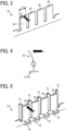
- the resin molded article 10 includes a beam-shaped portion 20 (rib-shaped portion) as a part of the resin molded article 10.
- the beam-shaped portion 20 is an integral part of the resin molded article 10 such that one end (that is a root portion of the lower side in FIG. 3 ) is connected to the resin molded article 10 and another end (that is a tip portion of the upper side in FIG. 3 ) is a free end.
- the beam-shaped portion 20 is made of the same resin material as that of the resin molded article 10, and is formed as a part of the resin molded article 10 by the same molding process.
- the beam-shaped portion 20 is formed so as to rise from a bottom portion 11 (see FIG. 4 ) of the resin molded article 10.
- a resin molded article includes a beam-shaped portion connected to the resin molded article and rising from a bottom of the resin molded article.
- the beam-shaped portion has one end as a root portion connected to the bottom of the resin molded article, and another end as a free end plastically deformable or breakable.
- the resin molded article 10 includes multiple beam-shaped portions 20 that are equal in at least length L and thickness H among the length L, thickness H, and width D.
- four beam-shaped portions 20 having a plate shape that are equal in shape (length L, thickness H, and width D) are arranged in parallel and spaced apart from each other in the width direction (a direction perpendicular to the direction to which the force F described below is applied and parallel to the width D).
- the reinforcing portion in the resin molded article, is in contact with the root portion, and the reinforcing portion has a thickness thicker than a thickness of surroundings of the reinforcing portion.
- the beam-shaped portion in the resin molded article, includes multiple beam-shaped portions, and the multiple beam-shaped portions have same length and thickness.
- the presence or absence of deterioration is determined based on the presence or absence of plastic deformation or fracture when another end (free end) of the beam-shaped portion 20 is deformed by applying a force F to the beam-shaped portion 20 with a human finger.
- the beam-shaped portion 20 of the resin molded article 10 in a disassembled state is deformed in the direction of the force F (represented by the arrow in FIG. 4 ) in a recycling factory, and the strength of the resin molded article 10 is evaluated based on whether plastic deformation or fracture has occurred.
- the beam-shaped portion 20 is deformed to a predetermined position (e.g., a marked position stamped on the resin molded article 10) when the beam-shaped portion 20 is deformed by applying the force F (external force) as described above.
- a deforming step that deforms the other end (free end) of the beam-shaped portion 20 is performed.
- a determining step that determines that deterioration has occurred in the resin molded article 10 is performed.
- the resin molded article 10 determined to be deteriorated is not reused, and only the resin molded article 10 determined not to be deteriorated is reused. Since the resin molded article 10 according to the present embodiment includes multiple beam-shaped portions 20, the deterioration of the resin molded article 10 can be determined multiple times.
- the resin molded article 10 according to the present embodiment can determine the deterioration of the resin molded article 10 by deforming the beam-shaped portion 20 integrated with the resin molded article 10 without using a measuring device, and thus the determination operation can be simply performed.
- a determining method includes deforming a free end of a beam-shaped portion of a resin molded article, the free end of the beam-shaped portion being plastically deformable or breakable.
- the deterioration of the resin molded article 10 is determined by deforming the other end (free end) of the beam-shaped portion 20, but the deterioration of the resin molded article 10 may be determined by fracturing the other end (free end) of the beam-shaped portion 20.
- a fracturing step is performed in which a force F (load) is applied to the beam-shaped portion 20 to deform the beam-shaped portion 20 until the other end of the beam-shaped portion is fractured.
- a determining step that determines whether deterioration has occurred in the resin molded article 10 is performed depending on the magnitude of the force F (load) when the beam-shaped portion 20 is fractured in the fracturing step.
- the resin molded article 10 is not reused, and in the case where the magnitude of the force F (load) at the time when the beam-shaped portion 20 is fractured exceeds the threshold value Fx, the resin molded article 10 is reused.
- the resin molded article 10 is reused (to be reused)
- the above-described fracturing step is performed on one of the multiple beam-shaped portions 20.
- the number of times of reuse can be counted by the number of beam-shaped portions 20 that have fractured among the multiple beam-shaped portions 20.
- the worker who determines the deterioration and the worker who assembles the apparatus 1 using the reused resin molded article 10 can grasp the number of times of reuse of the resin molded article 10 from the number of beam-shaped portions 20 that have fractured.
- a determining method includes applying a force to a free end of a beam-shaped portion of a resin molded article, breaking the free end of the beam-shaped portion by applying the force, and obtaining a magnitude of the force applied to the free end of the beam-shaped portion at a break the free end.
- the determining method further includes forming the beam-shaped portion including multiple beam-shaped portions having same length and thickness, breaking one of the multiple beam-shaped portions among the multiple beam-shaped portions, and counting a number of the beam-shaped portion broken among the multiple beam-shaped portions.
- the resin molded article 10 includes a restricting portion 15 that restricts the deformation amount ⁇ of the other end (free end) of the beam-shaped portion 20 when the other end is deformed.
- the restricting portion 15 is formed in a substantially plate shape so as to extend in the direction in which the beam-shaped portion 20 rises and at an interval with respect to the beam-shaped portion 20 in a state in which the other end of the beam-shaped portion 20 is not deformed (in a state in which the force F (external force) is not applied).
- the restricting portion 15 is made of the same resin material as that of the resin molded article 10, and is formed as a part of the resin molded article 10 by the same molding process.
- the restricting portion 15 is formed so as to rise from the bottom portion 11 (see FIG. 7 ) of the resin molded article 10.
- the "deforming step” described above is a step that deforms the beam-shaped portion 20 to a position at which the other end of the beam-shaped portion 20 abuts on the restricting portion 15.
- the restricting portion 15 allows deformation of the beam-shaped portion 20 to a predetermined position (i.e., position that abuts on the restricting portion 15). As a result, the deterioration can be stably determined.
- the resin molded article further includes a restricting portion to restrict a deformation amount of the free end of the beam-shaped portion.
- the restricting portion in the resin molded article, extends in a first direction in which the beam-shaped portion rises, the restricting portion has a gap with the beam-shaped portion in a second direction orthogonal to the first direction, and the free end of the beam-shaped portion deforms in the second direction.
- the determining method further includes restricting a deformation amount of the free end of the beam-shaped portion, and contacting the free end of the beam-shaped portion in the deforming with the restricting portion.
- the restricting portions 15 can be disposed on both sides (upper and lower sides in FIG. 6 ) such that the beam-shaped portion 20 is disposed between the restricting portions 15. In this case, the beam-shaped portion 20 may be deformed to any of the two sides at the time when deterioration is determined. As illustrated in FIG. 6 , it is preferable that the multiple restricting portions 15 are disposed at intervals in the width direction (i.e., left-right direction in FIG. 6 ) while obtaining a gap for applying the force F (load) to the beam-shaped portion 20.
- a reinforcing portion 16 that reinforces the root portion of one end of the beam-shaped portion 20 of the resin molded article 10 in the modification is disposed so as to restrict elastic deformation of the root portion.
- the reinforcing portion 16 is disposed at a position in contact with the root portion of the beam-shaped portion 20, and has a thickness (thickness in the longitudinal direction in FIG. 7 ) that is thicker than the thickness of the surroundings.
- the reinforcing portion 16 is made of the same resin material as that of the resin molded article 10, and is formed as a part of the resin molded article 10 by the same molding process.
- the reinforcing portion 16 is formed so as to rise from the bottom portion 11 (see FIG.
- the reinforcing portion 16 allows the beam-shaped portion 20 to be elastically deformed at a portion over the reinforcing portion 16 (i.e., variations are less likely to occur in an elastically deformed portion). As a result, the deterioration can be stably determined.
- the reinforcing portions 16 can be disposed on both sides of the beam-shaped portion 20 so as to hold the beam-shaped portion 20 between the reinforcing portions 16 (the left side and the right side of the beam-shaped portion 20 in FIG. 6 ). In this case, the above-described function of the reinforcing portion 16 is likely to exhibit.
- the resin molded article further includes a reinforcing portion adjacent to the root portion of the beam-shaped portion on the bottom of the resin molded article.
- the reinforcing portion restricts an elastic deformation of the root portion to reinforce the root portion.
- the beam-shaped portion 20 is deformed by a predetermined amount ⁇ under the restriction of the restricting portion 15, and the maximum stress ⁇ applied to the beam-shaped portion 20 can be obtained by the following equation based on the calculation equation of the deflection of the cantilever beam of the material mechanics.
- ⁇ 3 E H ⁇ / (2L 2 ), where E, H, and L represent the longitudinal elastic modulus, the thickness (see FIG. 3 ), and the length (see FIG. 3 ) of the beam-shaped portion 20, respectively.
- Equation 1 obtains the deformation ⁇
- Equation 2 obtains the maximum bending moment Mmax
- Equation 3 obtains the maximum stress ⁇ max.
- the applied maximum stress ⁇ that deforms the beam-shaped portion 20 by a predetermined amount ⁇ is a value determined by the longitudinal elastic modulus E (a value that has a small change even if the material deteriorates with elapsed time), the thickness H of the beam-shaped portion 20 (a value that does not change with elapsed time), and the length L of the beam-shaped portion 20 (a value that does not change with elapsed time).
- the deterioration determination can be performed with equivalent accuracy for all multiple beam-shaped portions 20 disposed at the resin molded article 10 as long as the thickness H and the length L are equal, even if the widths D are different. Even if deterioration occurs in the resin molded article 10 with elapsed time, the maximum stress ⁇ applied to the beam-shaped portion 20 does not change by deforming the beam-shaped portion 20 by a predetermined amount ⁇ . As a result, a highly accurate deterioration determination can be performed by simply applying a predetermined stress without using a measuring device.
- FIGS. 8A and 8B are graphs of the relation between strain ⁇ and stress ⁇ in the beam-shaped portion 20.
- FIG. 8A is a graph of an initial state in which the resin molded article 10 is not deteriorated
- FIG. 8B is a graph of an elapsed state in which the resin molded article 10 has deteriorated.
- the resin molded article 10 in the initial state, the resin molded article 10 is not deteriorated in strength.
- the resin molded article 10 is elastically deformed to a certain stress (range X1), and when the force exceeds the certain stress, the resin molded article 10 is plastically deformed.
- the stress at the time of plastic deformation or fracture can be basically regarded as the strength of the material (resin molded article 10).
- the longitudinal elastic modulus the slope of the graph in the elastic region
- the strength of the material (resin molded article 10) at this time is smaller than that in the state without deterioration (state illustrated in FIG. 8A ).
- the stress at a time when the tip of the beam-shaped portion 20 is deformed by applying the force F until the beam-shaped portion 20 abuts on the restricting portion 15 does not change before and after the deterioration as described above.
- the shape of the beam-shaped portion 20 such as the thickness H and the length L is set such that the maximum stress ⁇ at the time when the beam-shaped portion 20 is deformed by a predetermined amount ⁇ becomes a threshold value in the determination of the material strength of the resin molded article 10, the strength deterioration can be evaluated by the presence or absence of plastic deformation or fracture (breakage) at the time when the same stress F is applied to the beam-shaped portion 20.
- the strength deterioration of the resin molded article 10 caused by a decrease in molecular weight due to temperature, humidity, or ultraviolet rays occurs with elapsed time
- the strength deterioration can be simply determined by observing the presence or absence of plastic deformation or fracture at the time when the tip of the beam-shaped portion 20 is deformed by applying the force F until the beam-shaped portion 20 abuts on the restricting portion 15, without using a measuring device and without requiring the skill of an operator.
- the resin molded article 10 is a resin molded article made of a predetermined resin material
- the beam-shaped portion 20 is an integral part of the resin molded article 10 such that one end of the beam-shaped portion 20 is connected to the resin molded article 10 and another end of the beam-shaped portion 20 is a free end.
- the presence or absence of deterioration is determined by the presence or absence of plastic deformation or fracture when the other end of the beam-shaped portion 20 is deformed. Accordingly, the deterioration of the resin molded article 10 can be simply determined.
- the present disclosure is not limited to the present embodiment, and the present embodiment can be modified as appropriate in addition to the modifications suggested in the present embodiment within the scope of the technical idea of the present disclosure.
- the number, position, and shape of the constituent members described above are not limited to those in the present embodiment, and can be set to the number, position, or shape preferable for conducting the present embodiment.
- a resin molded article made of a predetermined resin material includes a beam-shaped portion including one end connecting to the resin molded article as a one body and another end of a free end.
- the deterioration of the resin molded article is determined by presence or absence of plastic deformation or fracture at a time when another portion of the beam-shaped portion is deformed.
- the resin molded article according to the first aspect further includes a restricting portion to restrict a deformation amount of another end at a time when another end of the beam-shaped portion is deformed.
- the restricting portion is formed so as to extend in a direction in which the beam-shaped portion rises at an interval with respect to the beam-shaped portion in a state where another end of the beam-shaped portion is not deformed.
- the resin molded article according to any one of the first to third aspects further includes a reinforcing portion to reinforce a root portion of the beam-shaped portion so as to restrict elastic deformation.
- the reinforcing portion is disposed at a position in which the reinforcing portion is in contact with the root portion, and a thickness of the reinforcing portion is thicker than a thickness of surroundings of the reinforcing portion.
- the beam-shaped portion includes multiple beam-shaped portions having the same length and thickness.
- the resin molded article includes a beam-shaped portion including one end connecting to the resin molded article as a one body and another end of a free end.
- the determining method for the deterioration of the resin molded article includes deforming another end of the beam-shaped portion, and determining deterioration of the resin molded article at a time when the beam-shaped portion is plastically deformed or fractured in the deforming.
- the resin molded article further includes a restricting portion to restrict a deformation amount of another end of the beam-shaped portion at a time when another end is deformed.
- a restricting portion to restrict a deformation amount of another end of the beam-shaped portion at a time when another end is deformed.
- another end of the beam-shaped portion is deformed to a position at which another end abuts on the restricting portion.
- the resin molded article includes a beam-shaped portion including one end connecting to the resin molded article as a one body and another end of a free end.
- the determining method for the deterioration of the resin molded article includes fracturing another end of the beam-shaped portion by applying a load to the beam-shaped portion to fracture and determining deterioration of the resin molded article based on the load at a time when the beam-shaped portion is fractured in the fracturing.
- the beam-shaped portion includes multiple beam-shaped portions having the same length and thickness.
- the fracturing is performed to at least one of the multiple beam-shaped portions.
- the number of times of reuse is counted by the number of beam-shaped portions that have fractured among the multiple beam-shaped portions.
- a resin molded article includes a beam-shaped portion connected to the resin molded article and rising from a bottom of the resin molded article.
- the beam-shaped portion has one end as a root portion connected to the bottom of the resin molded article, and another end as a free end plastically deformable or breakable.
- the resin molded article according to the eleventh aspect further includes a restricting portion to restrict a deformation amount of the free end of the beam-shaped portion.
- the restricting portion extends in a first direction in which the beam-shaped portion rises, the restricting portion has a gap with the beam-shaped portion in a second direction orthogonal to the first direction, and the free end of the beam-shaped portion deforms in the second direction.
- the resin molded article according to any one of the eleventh to thirteenth further includes a reinforcing portion adjacent to the root portion of the beam-shaped portion on the bottom of the resin molded article.
- the reinforcing portion restricts an elastic deformation of the root portion to reinforce the root portion.
- the reinforcing portion is in contact with the root portion, and the reinforcing portion has a thickness thicker than a thickness of surroundings of the reinforcing portion.
- the beam-shaped portion includes multiple beam-shaped portions, and the multiple beam-shaped portions have same length and thickness.
- a determining method includes deforming a free end of a beam-shaped portion of a resin molded article, the free end of the beam-shaped portion being plastically deformable or breakable.
- the determining method according to the seventeenth aspect further includes restricting a deformation amount of the free end of the beam-shaped portion, and contacting the free end of the beam-shaped portion in the deforming with the restricting portion.
- a determining method includes applying a force to a free end of a beam-shaped portion of a resin molded article, breaking the free end of the beam-shaped portion by applying the force, and obtaining a magnitude of the force applied to the free end of the beam-shaped portion at a break the free end.
- the determining method according to the nineteenth aspect further includes forming the beam-shaped portion including multiple beam-shaped portions having same length and thickness, breaking one of the multiple beam-shaped portions among the multiple beam-shaped portions, and counting a number of the beam-shaped portion broken among the multiple beam-shaped portions.
Landscapes
- General Physics & Mathematics (AREA)
- Engineering & Computer Science (AREA)
- Physics & Mathematics (AREA)
- Health & Medical Sciences (AREA)
- Life Sciences & Earth Sciences (AREA)
- Chemical & Material Sciences (AREA)
- Immunology (AREA)
- General Health & Medical Sciences (AREA)
- Biochemistry (AREA)
- Pathology (AREA)
- Analytical Chemistry (AREA)
- Aviation & Aerospace Engineering (AREA)
- Food Science & Technology (AREA)
- Medicinal Chemistry (AREA)
- Manufacturing & Machinery (AREA)
- Mechanical Engineering (AREA)
- Injection Moulding Of Plastics Or The Like (AREA)
- Investigating Strength Of Materials By Application Of Mechanical Stress (AREA)
Abstract
A resin molded article (10) includes a beam-shaped portion (20) connected to the resin molded article and rising from a bottom of the resin molded article. The beam-shaped portion (20) has one end as a root portion connected to the bottom of the resin molded article (10), and another end as a free end plastically deformable or breakable.
Description
- Embodiments of the present disclosure relate to a resin molded article made of a predetermined resin material such as a component of an apparatus, and a determining method for deterioration of the resin molded article.
- In the related art, in various apparatuses (e.g., industrial products), a resin molded article (i.e., resin parts) made of a predetermined resin material has been used as a component (e.g.,
Japanese Unexamined Patent Application Publication No. 2001-180782 Japanese Unexamined Patent Application Publication No. 2013-29371 - On the other hand,
Japanese Unexamined Patent Application Publication No. 2001-180782 Japanese Unexamined Patent Application Publication No. 2013-29371 - In the related art, since the deterioration of the resin molded article is determined by a measuring device, it takes time and effort.
- An object of the present disclosure is to solve the problems described above and to provide a resin molded article and a determining method for the deterioration of the resin molded article in a simple manner.
- According to an embodiment of the present disclosure, a resin molded article includes a beam-shaped portion connected to the resin molded article and rising from a bottom of the resin molded article. The beam-shaped portion has one end as a root portion connected to the bottom of the resin molded article, and another end as a free end plastically deformable or breakable.
- According to an embodiment of the present disclosure, a determining method includes deforming a free end of a beam-shaped portion of a resin molded article. The free end of the beam-shaped portion being plastically deformable or breakable.
- According to an embodiment of the present disclosure, a determining method includes applying a force to a free end of a beam-shaped portion of a resin molded article, breaking the free end of the beam-shaped portion by applying the force, and obtaining a magnitude of the force applied to the free end of the beam-shaped portion at a break the free end.
- According to embodiments of the present disclosure, a resin molded article and a determining method for the deterioration of the resin molded article in a simple manner can be provided.
- A more complete appreciation of the disclosure and many of the attendant advantages thereof will be readily obtained as the same becomes better understood by reference to the following detailed description when considered in connection with the accompanying drawings, wherein:
-
FIG. 1 is a perspective view of an apparatus according to an embodiment of the present disclosure; -
FIG. 2 is a perspective view of a resin molded article according to an embodiment of the present disclosure; -
FIG. 3 is a perspective view of a beam-shaped portion of the resin molded article inFIG. 2 ; -
FIG. 4 is a cross-sectional side view of the beam-shaped portion inFIG. 3 deformed; -
FIG. 5 is a perspective view of a beam-shaped portion and its surroundings according to a modification; -
FIG. 6 is a top view of the beam-shaped portion and its surroundings inFIG. 5 ; -
FIG. 7 is a cross-sectional side view of the beam-shaped portion inFIG. 5 deformed; -
FIG. 8A is a graph of the relation between stress and strain in a beam-shaped portion without deterioration; and -
FIG. 8B is a graph of the relation between stress and strain in a beam-shaped portion having deteriorated. - The accompanying drawings are intended to depict embodiments of the present disclosure and should not be interpreted to limit the scope thereof. The accompanying drawings are not to be considered as drawn to scale unless explicitly noted. Also, identical or similar reference numerals designate identical or similar components throughout the several views.
- In describing embodiments illustrated in the drawings, specific terminology is employed for the sake of clarity. However, the disclosure of this patent specification is not intended to be limited to the specific terminology so selected and it is to be understood that each specific element includes all technical equivalents that operate in a similar manner and achieve similar results.
- Referring now to the drawings, embodiments of the present disclosure are described below. As used herein, the singular forms "a," "an," and "the" are intended to include the plural forms as well, unless the context clearly indicates otherwise.
- Embodiments of the present disclosure are described in detail with reference to the drawings. In the drawings, the same or like reference signs denote like elements having substantially the same or corresponding configurations, and descriptions thereof may be omitted.
- As illustrated in
FIG. 1 , anapparatus 1 includes a resin moldedarticle 10 that is reusable. The resin moldedarticle 10 is made of a predetermined resin material (e.g., polycarbonate (PC) resin, polyethylene terephthalate (PET) resin, or acrylonitrile butadiene styrene (ABS) resin). After theapparatus 1 has finished its service in the market, theapparatus 1 is collected from the market,. Theapparatus 1 is disassembled in a recycling factory to extract the resin moldedarticle 10, and the degree of deterioration of the resin moldedarticle 10 is determined. The reuse of the resin moldedarticle 10 is determined depending on the degree of deterioration. - In the present embodiment, an image forming apparatus such as a printer is used as the
apparatus 1. However, theapparatus 1 is not limited to the image forming apparatus, and any industrial product can be an object. In the present embodiment, a resin exterior cover is used as the resin moldedarticle 10 that is reusable. However, the resin moldedarticle 10 that is reusable is not limited to the resin exterior cover, and any resin molded article can be an object. Further, in the present embodiment, the resin moldedarticle 10 is used as a component of theapparatus 1 distributed in the market. However, the resin moldedarticle 10 may be separately used as a product to be distributed in the market. - As illustrated to
FIGS. 2 and3 , the resin moldedarticle 10 according to the present embodiment includes a beam-shaped portion 20 (rib-shaped portion) as a part of the resin moldedarticle 10. However, the part does not interfere with the original function of the resin moldedarticle 10. The beam-shaped portion 20 is an integral part of the resin moldedarticle 10 such that one end (that is a root portion of the lower side inFIG. 3 ) is connected to the resin moldedarticle 10 and another end (that is a tip portion of the upper side inFIG. 3 ) is a free end. Specifically, the beam-shaped portion 20 is made of the same resin material as that of the resin moldedarticle 10, and is formed as a part of the resin moldedarticle 10 by the same molding process. The beam-shaped portion 20 is formed so as to rise from a bottom portion 11 (seeFIG. 4 ) of the resin moldedarticle 10. - According to an embodiment of the present disclosure, a resin molded article includes a beam-shaped portion connected to the resin molded article and rising from a bottom of the resin molded article. The beam-shaped portion has one end as a root portion connected to the bottom of the resin molded article, and another end as a free end plastically deformable or breakable.
- In particular, the resin molded
article 10 according to the present embodiment includes multiple beam-shaped portions 20 that are equal in at least length L and thickness H among the length L, thickness H, and width D. Specifically, four beam-shaped portions 20 having a plate shape that are equal in shape (length L, thickness H, and width D) are arranged in parallel and spaced apart from each other in the width direction (a direction perpendicular to the direction to which the force F described below is applied and parallel to the width D). - According to an embodiment of the present disclosure, in the resin molded article, the reinforcing portion is in contact with the root portion, and the reinforcing portion has a thickness thicker than a thickness of surroundings of the reinforcing portion.
- According to an embodiment of the present disclosure, in the resin molded article, the beam-shaped portion includes multiple beam-shaped portions, and the multiple beam-shaped portions have same length and thickness.
- In the present embodiment, as illustrated in
FIG. 4 , the presence or absence of deterioration (strength deterioration) is determined based on the presence or absence of plastic deformation or fracture when another end (free end) of the beam-shaped portion 20 is deformed by applying a force F to the beam-shaped portion 20 with a human finger. In other words, the beam-shaped portion 20 of the resin moldedarticle 10 in a disassembled state is deformed in the direction of the force F (represented by the arrow inFIG. 4 ) in a recycling factory, and the strength of the resin moldedarticle 10 is evaluated based on whether plastic deformation or fracture has occurred. In order to stably determine deterioration, it is preferable that the beam-shaped portion 20 is deformed to a predetermined position (e.g., a marked position stamped on the resin molded article 10) when the beam-shaped portion 20 is deformed by applying the force F (external force) as described above. - More specifically, as a determining method for the deterioration of the resin molded
article 10, a deforming step that deforms the other end (free end) of the beam-shaped portion 20 is performed. When plastic deformation or fracture occurs in the beam-shaped portion 20 in the deforming step, a determining step that determines that deterioration has occurred in the resin moldedarticle 10 is performed. Specifically, the resin moldedarticle 10 determined to be deteriorated is not reused, and only the resin moldedarticle 10 determined not to be deteriorated is reused. Since the resin moldedarticle 10 according to the present embodiment includes multiple beam-shapedportions 20, the deterioration of the resin moldedarticle 10 can be determined multiple times. - As described above, the resin molded
article 10 according to the present embodiment can determine the deterioration of the resin moldedarticle 10 by deforming the beam-shapedportion 20 integrated with the resin moldedarticle 10 without using a measuring device, and thus the determination operation can be simply performed. - According to an embodiment of the present disclosure, a determining method includes deforming a free end of a beam-shaped portion of a resin molded article, the free end of the beam-shaped portion being plastically deformable or breakable.
- In the present embodiment, the deterioration of the resin molded
article 10 is determined by deforming the other end (free end) of the beam-shapedportion 20, but the deterioration of the resin moldedarticle 10 may be determined by fracturing the other end (free end) of the beam-shapedportion 20. In such a case, a fracturing step is performed in which a force F (load) is applied to the beam-shapedportion 20 to deform the beam-shapedportion 20 until the other end of the beam-shaped portion is fractured. A determining step that determines whether deterioration has occurred in the resin moldedarticle 10 is performed depending on the magnitude of the force F (load) when the beam-shapedportion 20 is fractured in the fracturing step. Specifically, in the case where the magnitude of the force F (load) at the time when the beam-shapedportion 20 is fractured does not reach a threshold value Fx, the resin moldedarticle 10 is not reused, and in the case where the magnitude of the force F (load) at the time when the beam-shapedportion 20 is fractured exceeds the threshold value Fx, the resin moldedarticle 10 is reused. When the resin moldedarticle 10 is reused (to be reused), the above-described fracturing step is performed on one of the multiple beam-shapedportions 20. The number of times of reuse can be counted by the number of beam-shapedportions 20 that have fractured among the multiple beam-shapedportions 20. In other words, the worker who determines the deterioration and the worker who assembles theapparatus 1 using the reused resin moldedarticle 10 can grasp the number of times of reuse of the resin moldedarticle 10 from the number of beam-shapedportions 20 that have fractured. - According to an embodiment of the present disclosure, a determining method includes applying a force to a free end of a beam-shaped portion of a resin molded article, breaking the free end of the beam-shaped portion by applying the force, and obtaining a magnitude of the force applied to the free end of the beam-shaped portion at a break the free end.
- According to an embodiment of the present disclosure, in the determining method further includes forming the beam-shaped portion including multiple beam-shaped portions having same length and thickness, breaking one of the multiple beam-shaped portions among the multiple beam-shaped portions, and counting a number of the beam-shaped portion broken among the multiple beam-shaped portions.
- As illustrated in
FIGS. 5 to 7 , the resin moldedarticle 10 according to the modification includes a restrictingportion 15 that restricts the deformation amount δ of the other end (free end) of the beam-shapedportion 20 when the other end is deformed. The restrictingportion 15 is formed in a substantially plate shape so as to extend in the direction in which the beam-shapedportion 20 rises and at an interval with respect to the beam-shapedportion 20 in a state in which the other end of the beam-shapedportion 20 is not deformed (in a state in which the force F (external force) is not applied). Specifically, the restrictingportion 15 is made of the same resin material as that of the resin moldedarticle 10, and is formed as a part of the resin moldedarticle 10 by the same molding process. The restrictingportion 15 is formed so as to rise from the bottom portion 11 (seeFIG. 7 ) of the resin moldedarticle 10. The "deforming step" described above is a step that deforms the beam-shapedportion 20 to a position at which the other end of the beam-shapedportion 20 abuts on the restrictingportion 15. When the force F (external force or load) is applied to the beam-shapedportion 20 to deform, the restrictingportion 15 allows deformation of the beam-shapedportion 20 to a predetermined position (i.e., position that abuts on the restricting portion 15). As a result, the deterioration can be stably determined. - According to an embodiment of the present disclosure, the resin molded article further includes a restricting portion to restrict a deformation amount of the free end of the beam-shaped portion.
- According to an embodiment of the present disclosure, in the resin molded article, the restricting portion extends in a first direction in which the beam-shaped portion rises, the restricting portion has a gap with the beam-shaped portion in a second direction orthogonal to the first direction, and the free end of the beam-shaped portion deforms in the second direction.
- According to an embodiment of the present disclosure, in the determining method further includes restricting a deformation amount of the free end of the beam-shaped portion, and contacting the free end of the beam-shaped portion in the deforming with the restricting portion.
- As illustrated in
FIG. 6 , the restrictingportions 15 can be disposed on both sides (upper and lower sides inFIG. 6 ) such that the beam-shapedportion 20 is disposed between the restrictingportions 15. In this case, the beam-shapedportion 20 may be deformed to any of the two sides at the time when deterioration is determined. As illustrated inFIG. 6 , it is preferable that the multiple restrictingportions 15 are disposed at intervals in the width direction (i.e., left-right direction inFIG. 6 ) while obtaining a gap for applying the force F (load) to the beam-shapedportion 20. - As illustrated in
FIGS. 5 to 7 , a reinforcingportion 16 that reinforces the root portion of one end of the beam-shapedportion 20 of the resin moldedarticle 10 in the modification is disposed so as to restrict elastic deformation of the root portion. The reinforcingportion 16 is disposed at a position in contact with the root portion of the beam-shapedportion 20, and has a thickness (thickness in the longitudinal direction inFIG. 7 ) that is thicker than the thickness of the surroundings. Specifically, the reinforcingportion 16 is made of the same resin material as that of the resin moldedarticle 10, and is formed as a part of the resin moldedarticle 10 by the same molding process. The reinforcingportion 16 is formed so as to rise from the bottom portion 11 (seeFIG. 7 ) of the resin moldedarticle 10. When the force F (external force) is applied to the beam-shapedportion 20 to deform, the reinforcingportion 16 allows the beam-shapedportion 20 to be elastically deformed at a portion over the reinforcing portion 16 (i.e., variations are less likely to occur in an elastically deformed portion). As a result, the deterioration can be stably determined. As illustrated inFIG. 7 , the reinforcingportions 16 can be disposed on both sides of the beam-shapedportion 20 so as to hold the beam-shapedportion 20 between the reinforcing portions 16 (the left side and the right side of the beam-shapedportion 20 inFIG. 6 ). In this case, the above-described function of the reinforcingportion 16 is likely to exhibit. - According to an embodiment of the present disclosure, in the resin molded article further includes a reinforcing portion adjacent to the root portion of the beam-shaped portion on the bottom of the resin molded article. The reinforcing portion restricts an elastic deformation of the root portion to reinforce the root portion.
- In the "deforming step" in the modification, the beam-shaped
portion 20 is deformed by a predetermined amount δ under the restriction of the restrictingportion 15, and the maximum stress σ applied to the beam-shapedportion 20 can be obtained by the following equation based on the calculation equation of the deflection of the cantilever beam of the material mechanics. σ = 3 E H δ / (2L2), where E, H, and L represent the longitudinal elastic modulus, the thickness (seeFIG. 3 ), and the length (seeFIG. 3 ) of the beam-shapedportion 20, respectively. The above equation is obtained fromEquations 1 to 3 below.Equation 1 obtains the deformation δ, Equation 2 obtains the maximum bending moment Mmax, and Equation 3 obtains the maximum stress σmax.


- In
Equations 1 to 3, F represents a load applied to the beam-shaped portion 20 (seeFIG. 3 ), I represents a second moment of area (= D H3 / 12), D represents a width (seeFIG. 3 ), and Z represents a section modulus (= D H2 / 6). - As can be understood from the above equations, the applied maximum stress σ that deforms the beam-shaped
portion 20 by a predetermined amount δ is a value determined by the longitudinal elastic modulus E (a value that has a small change even if the material deteriorates with elapsed time), the thickness H of the beam-shaped portion 20 (a value that does not change with elapsed time), and the length L of the beam-shaped portion 20 (a value that does not change with elapsed time). Thus, since the value of the width D of the beam-shapedportion 20 is not related to the maximum stress σ, the deterioration determination can be performed with equivalent accuracy for all multiple beam-shapedportions 20 disposed at the resin moldedarticle 10 as long as the thickness H and the length L are equal, even if the widths D are different. Even if deterioration occurs in the resin moldedarticle 10 with elapsed time, the maximum stress σ applied to the beam-shapedportion 20 does not change by deforming the beam-shapedportion 20 by a predetermined amount δ. As a result, a highly accurate deterioration determination can be performed by simply applying a predetermined stress without using a measuring device. -
FIGS. 8A and 8B are graphs of the relation between strain ε and stress σ in the beam-shapedportion 20.FIG. 8A is a graph of an initial state in which the resin moldedarticle 10 is not deteriorated, andFIG. 8B is a graph of an elapsed state in which the resin moldedarticle 10 has deteriorated. As illustrated inFIG. 8A , in the initial state, the resin moldedarticle 10 is not deteriorated in strength. When a force is applied to the resin molded article 10 (beam-shaped portion 20), the resin moldedarticle 10 is elastically deformed to a certain stress (range X1), and when the force exceeds the certain stress, the resin moldedarticle 10 is plastically deformed. When the deformation is further increased, the resin moldedarticle 10 is fractured (range X2). The stress at the time of plastic deformation or fracture can be basically regarded as the strength of the material (resin molded article 10). By contrast, as illustrated inFIG. 8B , when the strength of the resin moldedarticle 10 deteriorates due to, for example, a decrease in the molecular weight of the resin material caused by heat, or ultraviolet rays, or chemicals with elapsed time, the longitudinal elastic modulus (the slope of the graph in the elastic region) hardly changes. However, deterioration such as sudden fracture with almost no plastic deformation is likely to occur with a stress smaller than that in a state where there is no deterioration. The strength of the material (resin molded article 10) at this time is smaller than that in the state without deterioration (state illustrated inFIG. 8A ). - In an embodiment of the present disclosure, the stress at a time when the tip of the beam-shaped
portion 20 is deformed by applying the force F until the beam-shapedportion 20 abuts on the restrictingportion 15 does not change before and after the deterioration as described above. When the shape of the beam-shapedportion 20 such as the thickness H and the length L is set such that the maximum stress σ at the time when the beam-shapedportion 20 is deformed by a predetermined amount δ becomes a threshold value in the determination of the material strength of the resin moldedarticle 10, the strength deterioration can be evaluated by the presence or absence of plastic deformation or fracture (breakage) at the time when the same stress F is applied to the beam-shapedportion 20. Thus, even when the strength deterioration of the resin moldedarticle 10 caused by a decrease in molecular weight due to temperature, humidity, or ultraviolet rays occurs with elapsed time, the strength deterioration can be simply determined by observing the presence or absence of plastic deformation or fracture at the time when the tip of the beam-shapedportion 20 is deformed by applying the force F until the beam-shapedportion 20 abuts on the restrictingportion 15, without using a measuring device and without requiring the skill of an operator. - As described above, the resin molded
article 10 according to the present embodiment is a resin molded article made of a predetermined resin material, and the beam-shapedportion 20 is an integral part of the resin moldedarticle 10 such that one end of the beam-shapedportion 20 is connected to the resin moldedarticle 10 and another end of the beam-shapedportion 20 is a free end. The presence or absence of deterioration is determined by the presence or absence of plastic deformation or fracture when the other end of the beam-shapedportion 20 is deformed. Accordingly, the deterioration of the resin moldedarticle 10 can be simply determined. - It is obvious that the present disclosure is not limited to the present embodiment, and the present embodiment can be modified as appropriate in addition to the modifications suggested in the present embodiment within the scope of the technical idea of the present disclosure. In addition, the number, position, and shape of the constituent members described above are not limited to those in the present embodiment, and can be set to the number, position, or shape preferable for conducting the present embodiment.
- Aspects of the present disclosure are, for example, as follows.
- A resin molded article made of a predetermined resin material includes a beam-shaped portion including one end connecting to the resin molded article as a one body and another end of a free end. The deterioration of the resin molded article is determined by presence or absence of plastic deformation or fracture at a time when another portion of the beam-shaped portion is deformed.
- The resin molded article according to the first aspect, further includes a restricting portion to restrict a deformation amount of another end at a time when another end of the beam-shaped portion is deformed.
- In the resin molded article according to the second aspect, the restricting portion is formed so as to extend in a direction in which the beam-shaped portion rises at an interval with respect to the beam-shaped portion in a state where another end of the beam-shaped portion is not deformed.
- The resin molded article according to any one of the first to third aspects, further includes a reinforcing portion to reinforce a root portion of the beam-shaped portion so as to restrict elastic deformation.
- In the resin molded article according to the fourth aspect, the reinforcing portion is disposed at a position in which the reinforcing portion is in contact with the root portion, and a thickness of the reinforcing portion is thicker than a thickness of surroundings of the reinforcing portion.
- In the resin molded article according to any one of the first to fifth aspect, the beam-shaped portion includes multiple beam-shaped portions having the same length and thickness.
- In a determining method for deterioration of a resin molded article made of a predetermined resin material, the resin molded article includes a beam-shaped portion including one end connecting to the resin molded article as a one body and another end of a free end. The determining method for the deterioration of the resin molded article includes deforming another end of the beam-shaped portion, and determining deterioration of the resin molded article at a time when the beam-shaped portion is plastically deformed or fractured in the deforming.
- In the determining method for the deterioration of the resin molded article according to the seventh aspect, the resin molded article further includes a restricting portion to restrict a deformation amount of another end of the beam-shaped portion at a time when another end is deformed. In the deforming, another end of the beam-shaped portion is deformed to a position at which another end abuts on the restricting portion.
- In a determining method for deterioration of a resin molded article made of a predetermined resin material, the resin molded article includes a beam-shaped portion including one end connecting to the resin molded article as a one body and another end of a free end. The determining method for the deterioration of the resin molded article includes fracturing another end of the beam-shaped portion by applying a load to the beam-shaped portion to fracture and determining deterioration of the resin molded article based on the load at a time when the beam-shaped portion is fractured in the fracturing.
- In the determining method for the deterioration of the resin molded article according to the ninth aspect, the beam-shaped portion includes multiple beam-shaped portions having the same length and thickness. When the resin-molded article is reused, the fracturing is performed to at least one of the multiple beam-shaped portions. The number of times of reuse is counted by the number of beam-shaped portions that have fractured among the multiple beam-shaped portions.
- A resin molded article includes a beam-shaped portion connected to the resin molded article and rising from a bottom of the resin molded article. The beam-shaped portion has one end as a root portion connected to the bottom of the resin molded article, and another end as a free end plastically deformable or breakable.
- The resin molded article according to the eleventh aspect further includes a restricting portion to restrict a deformation amount of the free end of the beam-shaped portion.
- In the resin molded article according to the twelfth aspect, the restricting portion extends in a first direction in which the beam-shaped portion rises, the restricting portion has a gap with the beam-shaped portion in a second direction orthogonal to the first direction, and the free end of the beam-shaped portion deforms in the second direction.
- The resin molded article according to any one of the eleventh to thirteenth further includes a reinforcing portion adjacent to the root portion of the beam-shaped portion on the bottom of the resin molded article. The reinforcing portion restricts an elastic deformation of the root portion to reinforce the root portion.
- In the resin molded article according to the fourteenth aspect, the reinforcing portion is in contact with the root portion, and the reinforcing portion has a thickness thicker than a thickness of surroundings of the reinforcing portion.
- In the resin molded article according to any one of the eleventh to fifteenth aspects, the beam-shaped portion includes multiple beam-shaped portions, and
the multiple beam-shaped portions have same length and thickness. - A determining method includes deforming a free end of a beam-shaped portion of a resin molded article, the free end of the beam-shaped portion being plastically deformable or breakable.
- In the determining method according to the seventeenth aspect further includes restricting a deformation amount of the free end of the beam-shaped portion, and contacting the free end of the beam-shaped portion in the deforming with the restricting portion.
- A determining method includes applying a force to a free end of a beam-shaped portion of a resin molded article, breaking the free end of the beam-shaped portion by applying the force, and obtaining a magnitude of the force applied to the free end of the beam-shaped portion at a break the free end.
- In the determining method according to the nineteenth aspect further includes forming the beam-shaped portion including multiple beam-shaped portions having same length and thickness, breaking one of the multiple beam-shaped portions among the multiple beam-shaped portions, and counting a number of the beam-shaped portion broken among the multiple beam-shaped portions.
- The above-described embodiments are illustrative and do not limit the present invention. Thus, numerous additional modifications and variations are possible in light of the above teachings. For example, elements and/or features of different illustrative embodiments may be combined with each other and/or substituted for each other within the scope of the present invention.
Claims (10)
- A resin molded article (10) comprising:
a beam-shaped portion (20) connected to the resin molded article and rising from a bottom of the resin molded article, the beam-shaped portion (20) having:one end as a root portion connected to the bottom of the resin molded article (10); andanother end as a free end plastically deformable or breakable. - The resin molded article (10) according to claim 1, further comprising a restricting portion (15) to restrict a deformation amount of the free end of the beam-shaped portion (10).
- The resin molded article (10) according to claim 2,wherein the restricting portion (15) extends in a first direction in which the beam-shaped portion (20) rises,the restricting portion (15) has a gap with the beam-shaped portion (20) in a second direction orthogonal to the first direction, andthe free end of the beam-shaped portion (20) deforms in the second direction.
- The resin molded article (10) according to claim 1 or 2, further comprising a reinforcing portion (16) adjacent to the root portion of the beam-shaped portion (10) on the bottom of the resin molded article,
wherein the reinforcing portion (16) restricts an elastic deformation of the root portion to reinforce the root portion. - The resin molded article (10) according to claim 4,wherein the reinforcing portion (16) is in contact with the root portion,the reinforcing portion (16) has a thickness thicker than a thickness of surroundings of the reinforcing portion (16).
- The resin molded article according to claim 1 or 2,wherein the beam-shaped portion (20) includes multiple beam-shaped portions, andthe multiple beam-shaped portions have same length and thickness.
- A determining method comprising:
deforming a free end of a beam-shaped portion (20) of a resin molded article (10), the free end of the beam-shaped portion (20) being plastically deformable or breakable. - The determining method according to claim 7, further comprising:restricting a deformation amount of the free end of the beam-shaped portion (20), andcontacting the free end of the beam-shaped portion in the deforming with the restricting portion.
- A determining method comprising:applying a force to a free end of a beam-shaped portion (20) of a resin molded article (10);breaking the free end of the beam-shaped portion (20) by applying the force; andobtaining a magnitude of the force applied to the free end of the beam-shaped portion (20) at a break of the free end.
- The determining method according to claim 9, further comprising:forming the beam-shaped portion (20) including multiple beam-shaped portions having same length and thickness;breaking one of the multiple beam-shaped portions among the multiple beam-shaped portions; andcounting a number of the beam-shaped portion (20) broken among the multiple beam-shaped portions.
Applications Claiming Priority (1)
| Application Number | Priority Date | Filing Date | Title |
|---|---|---|---|
| JP2023101490A JP2025001799A (en) | 2023-06-21 | 2023-06-21 | Resin molded product and method for determining degradation of resin molded product |
Publications (1)
| Publication Number | Publication Date |
|---|---|
| EP4480662A1 true EP4480662A1 (en) | 2024-12-25 |
Family
ID=91469968
Family Applications (1)
| Application Number | Title | Priority Date | Filing Date |
|---|---|---|---|
| EP24181000.1A Pending EP4480662A1 (en) | 2023-06-21 | 2024-06-10 | Resin molded article and determining method |
Country Status (4)
| Country | Link |
|---|---|
| US (1) | US20240426697A1 (en) |
| EP (1) | EP4480662A1 (en) |
| JP (1) | JP2025001799A (en) |
| CN (1) | CN119178675A (en) |
Citations (4)
| Publication number | Priority date | Publication date | Assignee | Title |
|---|---|---|---|---|
| JP2001180782A (en) | 1999-12-28 | 2001-07-03 | Toshiba Corp | Semiconductor component storage tray and method for determining reuse thereof |
| JP2013029371A (en) | 2011-07-27 | 2013-02-07 | Sumitomo Wiring Syst Ltd | Evaluation method of heat history of molding |
| CN114728455A (en) * | 2019-11-25 | 2022-07-08 | 株式会社村田制作所 | Resin molded article, battery pack, and method for inspecting resin molded article |
| CN115071001A (en) * | 2021-03-10 | 2022-09-20 | Fit股份公司 | Method for producing an elastically deformable molded part |
-
2023
- 2023-06-21 JP JP2023101490A patent/JP2025001799A/en active Pending
-
2024
- 2024-06-07 CN CN202410735131.8A patent/CN119178675A/en active Pending
- 2024-06-10 EP EP24181000.1A patent/EP4480662A1/en active Pending
- 2024-06-20 US US18/748,601 patent/US20240426697A1/en active Pending
Patent Citations (4)
| Publication number | Priority date | Publication date | Assignee | Title |
|---|---|---|---|---|
| JP2001180782A (en) | 1999-12-28 | 2001-07-03 | Toshiba Corp | Semiconductor component storage tray and method for determining reuse thereof |
| JP2013029371A (en) | 2011-07-27 | 2013-02-07 | Sumitomo Wiring Syst Ltd | Evaluation method of heat history of molding |
| CN114728455A (en) * | 2019-11-25 | 2022-07-08 | 株式会社村田制作所 | Resin molded article, battery pack, and method for inspecting resin molded article |
| CN115071001A (en) * | 2021-03-10 | 2022-09-20 | Fit股份公司 | Method for producing an elastically deformable molded part |
Also Published As
| Publication number | Publication date |
|---|---|
| US20240426697A1 (en) | 2024-12-26 |
| CN119178675A (en) | 2024-12-24 |
| JP2025001799A (en) | 2025-01-09 |
Similar Documents
| Publication | Publication Date | Title |
|---|---|---|
| US8990028B2 (en) | Fracture prediction method, device, a program arrangement and computer-accessible medium therefor | |
| US20170350838A1 (en) | Electric measuring cartridge, biological sample electric measuring device, and biological sample electric measuring method | |
| US6314819B1 (en) | Method for measuring adhesion strength of resin material | |
| JP6569209B2 (en) | Electrical measurement cartridge, electrical measurement apparatus, and electrical measurement method | |
| JP5668532B2 (en) | Simulation method and material parameter identification method | |
| Lienhard et al. | Strain rate dependent multiaxial characterization of long fiber reinforced plastic | |
| Rezazadeh et al. | Thermoelastic damping in a nonlocal nano-beam resonator as NEMS based on the type III of Green–Naghdi theory (with energy dissipation) | |
| EP4375634A1 (en) | Method for measuring residual stress in thin plate | |
| Koch et al. | Correlations between indentation hardness and yield stress in thermoplastic polymers | |
| US20240426697A1 (en) | Resin molded article and determining method | |
| WO2014003184A1 (en) | Program for outputting stress-strain curve equations and device for the same, evaluation method for physical properties of elastic materials, and design method for elastic materials | |
| US20030053515A1 (en) | Method for analyzing thermal deformation | |
| EP4491366A1 (en) | Resin molded article and determining method | |
| JP2024082720A (en) | Materials characterization and analysis methods | |
| US20160283624A1 (en) | Simulation method for polymer material | |
| US7203604B2 (en) | Method of predicting mechanical behavior of polymers | |
| EP4484116A1 (en) | Resin molded article and method for determining deterioration of resin molded article | |
| Vaňková et al. | Identification of temperature-dependent parameters for an elastic–plastic-damage material model of 3D-printed PETG | |
| US20180156681A1 (en) | High output charpy sensor body | |
| KR102317640B1 (en) | Specimen fixation apparatus for shear testing device | |
| US6581473B2 (en) | Method for analyzing creep characteristic of a plastic molded substance | |
| Akhtar et al. | Predicting the surface elastic parameters of soft solids using multi-output decision tree regressor | |
| KR101203635B1 (en) | Valuation method for forming character of ferrite stainless steel | |
| WO2005067379A2 (en) | A test device and method for measuring strength | |
| JP6755782B2 (en) | Method for identifying material parameters of rubber-like materials |
Legal Events
| Date | Code | Title | Description |
|---|---|---|---|
| PUAI | Public reference made under article 153(3) epc to a published international application that has entered the european phase |
Free format text: ORIGINAL CODE: 0009012 |
|
| STAA | Information on the status of an ep patent application or granted ep patent |
Free format text: STATUS: REQUEST FOR EXAMINATION WAS MADE |
|
| 17P | Request for examination filed |
Effective date: 20240610 |
|
| AK | Designated contracting states |
Kind code of ref document: A1 Designated state(s): AL AT BE BG CH CY CZ DE DK EE ES FI FR GB GR HR HU IE IS IT LI LT LU LV MC ME MK MT NL NO PL PT RO RS SE SI SK SM TR |