EP4480633A1 - Manipulating device for extracting workpieces from cnc lathe and placing them on pallets - Google Patents
Manipulating device for extracting workpieces from cnc lathe and placing them on pallets Download PDFInfo
- Publication number
- EP4480633A1 EP4480633A1 EP24182072.9A EP24182072A EP4480633A1 EP 4480633 A1 EP4480633 A1 EP 4480633A1 EP 24182072 A EP24182072 A EP 24182072A EP 4480633 A1 EP4480633 A1 EP 4480633A1
- Authority
- EP
- European Patent Office
- Prior art keywords
- gripper
- arm
- workpiece
- trolley
- palletizing
- Prior art date
- Legal status (The legal status is an assumption and is not a legal conclusion. Google has not performed a legal analysis and makes no representation as to the accuracy of the status listed.)
- Pending
Links
Images



Classifications
-
- B—PERFORMING OPERATIONS; TRANSPORTING
- B23—MACHINE TOOLS; METAL-WORKING NOT OTHERWISE PROVIDED FOR
- B23Q—DETAILS, COMPONENTS, OR ACCESSORIES FOR MACHINE TOOLS, e.g. ARRANGEMENTS FOR COPYING OR CONTROLLING; MACHINE TOOLS IN GENERAL CHARACTERISED BY THE CONSTRUCTION OF PARTICULAR DETAILS OR COMPONENTS; COMBINATIONS OR ASSOCIATIONS OF METAL-WORKING MACHINES, NOT DIRECTED TO A PARTICULAR RESULT
- B23Q7/00—Arrangements for handling work specially combined with or arranged in, or specially adapted for use in connection with, machine tools, e.g. for conveying, loading, positioning, discharging, sorting
- B23Q7/04—Arrangements for handling work specially combined with or arranged in, or specially adapted for use in connection with, machine tools, e.g. for conveying, loading, positioning, discharging, sorting by means of grippers
-
- B—PERFORMING OPERATIONS; TRANSPORTING
- B23—MACHINE TOOLS; METAL-WORKING NOT OTHERWISE PROVIDED FOR
- B23Q—DETAILS, COMPONENTS, OR ACCESSORIES FOR MACHINE TOOLS, e.g. ARRANGEMENTS FOR COPYING OR CONTROLLING; MACHINE TOOLS IN GENERAL CHARACTERISED BY THE CONSTRUCTION OF PARTICULAR DETAILS OR COMPONENTS; COMBINATIONS OR ASSOCIATIONS OF METAL-WORKING MACHINES, NOT DIRECTED TO A PARTICULAR RESULT
- B23Q2707/00—Automatic supply or removal of metal workpieces
- B23Q2707/003—Automatic supply or removal of metal workpieces in a lathe
Definitions
- the invention concerns manipulation of finished workpieces, especially when turning on CNC lathes with two spindles, more precisely it concerns extraction of workpieces from the counter-spindle of the machine and their transport out of the machine space.
- the invention also relates to oriented storage of the workpiecies into storage palletes as a subsequent system of the complete production line.
- Robots and some manipulators required that the machine is stopped during the manipulation, such creating unproductive time, which is a major disadvantage especially for workpieces with short machining times. None of the systems allow oriented workpiece placement, i.e. oriented placement, which is important for subsequent automatic measurement and at the same time uninterrupted operation of the CNC lathe. In the case of gantry manipulators, the solution is space consuming and usually requires penetrations through the CNC lathe structure. In cases with the storage of final workpieces in containers, surface damage of workpieces often occurs, which is particularly harmful for edges and functional surfaces.
- Document CZ26194U1 discloses an automatic vertical stacker for handling with parts, that are placed on pallets and loaded into the stacker, which are then manipulated by a robotic arm.
- the stacker comprises a stationary tray in which a cage is movably arranged in the vertical direction, to which a supply trolley is removably adjacent on one side and a stationary picking table is adjacent on the opposite side.
- the supply trolley consists of a prismatic frame fitted with pallet guide rails.
- the cage contains a set of pairs of guide rails which are substantially the same vertical pitch and horizontal spacing as the guide rails on the supply trolley.
- the picking table is constructed as a prismatic weldment having a pair of guide rails on its upper part at the same horizontal spacing as the rails, and is provided with a feeder for catching the pallet from the cage and removing and retracting it.
- the aim of the invention is to introduce a manipulation device for extraction of finished workpieces from the CNC lathe, which allows their transport out of the machine space and forwarding into grippers of the palletizing module, to ensure oriented placement into storage pallets.
- manipulating device for extracting workpieces from CNC lathe and placing them on pallets according to the characterizing part of claim 1.
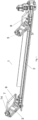
- Fig. 1 shows the linear workpiece transport module with a trolley equipped with a workpiece gripper in its extreme positions
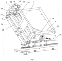
- Fig. 2 shows a detail of the gripper trolley and the front transfer plate
- Fig. 3 is a detail of the gripper trolley and rear guiding plate
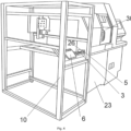
- Fig. 4 is a simplified view of the CNC lathe with palletizing module
- Fig. 5 is a detail of the gripper trolley and gripper of palletizing arm just before workpiece transfer
- Fig. 6 is a detail of the gripper of palletizing arm when inserting the workpiece into the pallet with the first grasping part downwards
- Fig. 7 is a detail of the trolley in the gripper area and the stationary gripper when tranfering the workpiece
- Fig. 1 shows the linear workpiece transport module with a trolley equipped with a workpiece gripper in its extreme positions
- Fig. 2 shows a detail of the gripper trolley and the front transfer plate
- Fig. 3 is a detail of the gripper trolley and rear guiding plate
- Fig. 8 is a view of the stationary gripper and the gripper of palletizing arm just before transfering the workpiece
- Fig. 9 is a detail of gripper of the palletizing arm when the workpiece is inserted into the pallet with the shaped third part downwards
- Fig. 10 is a detail of the palletizing module according to the invention with gripper of the palletizing arm and pallet in the bottom view
- Fig. 11 is a variant of the movable driving element.
- Fig. 1 illustrates a linear workpiece transport module 1 having a longitudinal movable belt 2, by means of which a trolley 3 of a gripper 5 for workpieces 14 extracted from a CNC lathe is transfered into the space of a palletizing module 10 arranged adjacent thereto on the right side of the movable belt 2 by the view from the interior of the lathe outwards. It can be seen that on each side of the movable belt 2 there are guiding plates 6, 7 arranged whose interaction with the trolley 3 will be discussed later and these plates 6, 7 are provided with guide grooves 8, 9.
- the trolley 3 of the gripper 5 is made as a kinematic body made as a parallelogram.
- the trolley 3 is arranged by its lower part on a carrier 24, which can be carried, for example, by a toothed belt 25 or made as a power nut through which the trolley 3 is carried by means of a power screw.
- the carrier 24 is guided by a rail 39, which is shown in Fig. 3 .
- This allows the trolley 3 of the gripper 5 to move from one end of the movable belt 2 to the other.
- the trolley 3 has two parallel arms, namely a rear arm 29 and a front arm 28, both in the form of a frame, the front arm 28 being pivotally connected to the carrier 24 via pins.
- the front arm 28 is connected to the rear arm 29 via a rectangular support plate 31 provided with pins on which the gripper 5 for the workpiece 14 is arranged.
- the carrier 24 is provided on one side, facing away from the movable belt 2, with an obliquely chamfered surface on which the front arm 28 is arranged, so that the trolley 3 is positioned at an angle to the movable belt 2, but may also be arranged perpendicular to the movable belt 2.
- Fig. 2 shows the situation after the trolley 3 has been erected in the workspace 30 of the CNC lathe.
- the upper pulley 20 is arranged at the top of the front arm 28, which engages the second guide groove 9 and rises itself from horizontal position to an upright position to allow the workpiece 14 to be extracted from the machine chuck.
- Fig. 3 shows a detail of the trolley 3 of gripper 5 and the rear guiding plate 6. It can be seen that, on the adjacent side to the rear guiding plate 6, a lower pulley 21 is arranged at the bottom of the front arm 28 which engages the first guide groove 8 and from the horizontal transport position is erected to allow the workpiece 14 to be extracted by the gripper 34 of the palletizing arm 27 or the stationary gripper 32.
- the rear guiding plate 6 is arranged lower relativly to the front transfer plate 7 to allow the lower pulley 21 to be driven into the first guide groove 8, since the lower pulley 21 is lower than the upper pulley 20.
- the upper pulley 20 is driven into the second guide groove 9, lifting the trolley 3 to the position shown in Fig. 2 .
- the rear guiding plate 6 is already located outside the CNC lathe in the palletizing module 10, and therein the gripper 34 of the palletizing arm 27 is arranged, shown in Fig. 5 , with the axial clamp 4 having grasping throughs 38 inside, which take the workpiece 14 from the gripper 5 and takes care of placing the workpiece 14 on the pallet 13.
- the two plates 6, 7 have the same inclination.
- Fig. 4 shows a simplified view of the CNC lathe 23 with its workspace 30, from which the workpiece 14 is extracted. It can be seen that a through opening 26 is made in the side of the machine, into which the trolley 3 enters and exits in a horizontal transport position. In known solutions, a conveyor is guided through this opening 26, on which the workpiece 14 inside the workspace 30 is mechanically laid down. The conveyor carries the workpiece 14 from the workspace to a storage box, into which it is freely lowered from the conveyor.
- the front transfer plate 7 is arranged inside the workspace 30, where, behind the opening 26, thanks to the second guide groove 9 of the front transfer plate 7, into which the upper pulley 20 is driven, the trolley 3 is lifted from tilted state together with the gripper 5, and the latter can remove the workpiece 14 from the finishing spindle. After the workpiece 14 has been extracted, again thanks to the second guide groove 9 of the transfer plate 7, during the backward movement, the trolley 3 with the workpiece 14 is laid down the transport movable belt 2 so, that it can pass through the through opening 26 in the opposite direction.
- the aforementioned front transfer plate 7 is provided with the second guide groove 9, which has two functions.
- the first phase via the upper pulley 20, it lifts the trolley 3 to the upper position for grasping the workpiece 14.
- the further function occurs whereby the upper pulley 20 lowers the trolley 3 to a laid position to allow it to pass back through the opening 26.
- first guide groove 8 which again has two functions.
- the trolley 3 is lifted to the upper position for grasping the workpiece 14 by the gripper 34 of the palletizing arm 27, which then takes care of the correct orientation of the workpiece 14 on the pallet 13.
- the further function takes place whereby the trolley 3 is again lowered via the lower pulley 21, thanks to the first guiding groove 8 on the plate 6 to a tilted position so that it can again pass with the movable belt 2 through the opening 26.
- the trolley 3 is lifted on the plate 7 in the manner described above and takes the new workpiece 14.
- the palletizing arm 27 can be seen in Fig. 10 .
- the plates 6, 7 are arranged on the edges of the movable belt 2 at any angle corresponding to the angle at which the trolley 3 is arranged on the carrier 24.
- the trolley 3 is moved from an upright to a horizontal tilted position in the same plane relative to the movable belt 2.
- the first guide groove 8 is orientated in an arc from top to bottom on the rear guiding plate 6, while the second guide groove 9 is also oriented in an arc but from bottom to the top on the front transfer plate 7.
- those are provided with guide widening 22 on their edges on the plates 7, 6.
- the CNC lathe 23 has two spindles arranged opposite each other, wherein on one spindle which is further away from the through opening 26 a first grasping part 15 of the workpiece 14 is machined and on the opposite spindle a second grasping part 16 of the workpiece 14 is made, wherein the workpiece is clamped at the end of the machining in the counter-spindle of the machine on the shaped third part 17.
- the trolley 3 on the linear transport module 1 receives the workpiece 14 by clamping it with the gripper 5 by the first grasping part 15, as shown in Fig. 2 .
- the workpiece 14 in the embodiment shown has three parts, which may be cylindrical or square and may be further provided with an additional element, for example a flattening, a groove, a transverse or longitudinal opening, etc.
- the grasping surface for the gripper 5 is the first grasping part 15, see Fig. 2
- the aim is, in the first case, that the workpiece 14 is inserted into the pallet 13 by the first grasping part 15, as shown in Fig. 6 , or, in the second case, that the workpiece 14 is inserted into the pallet 13 by the shaped third part 17, as shown in Fig. 9 .
- the workpiece 14 is ready in position for transfer to the gripper 34 of the palletizing arm 27.
- the first possibility is that the workpiece 14 is passed directly to the gripper 34 of the palletizing arm 27, which grips it with the axial gripper 4 by the shaped third part 17, as shown in Fig. 5 .
- the workpiece 14 is then placed in the pallet so that the workpiece 14 is placed in the opening of the pallet 13 by the first grasping part 15.
- the first grasping part 15 is after being taken up by the gripper 34 free and by this part 15 the workpiece 14 is placed after rotation of the gripper 34 by 90° into position in the pallet 13, see Fig. 6 .
- the second possibility is, that the workpiece 14 is taken up by the stationary gripper 32, which is arranged in front of the trolley 3 and therefore in front of the workpiece 14.
- the stationary gripper 32 shown in Fig. 7 is arranged here, which is aon the stand 35.
- the stationary gripper 32 grasps the workpiece 14 by the second grasping part 16 with the clamp 33.
- the gripper 34 of the palletizing arm 27 arrives from behind, as shown in Fig. 8 , and grasps the workpiece 14 by the first grasping part 15.
- Fig. 9 then shows the next phase, in which in this case the workpiece 14 is then placed in the pallet 13 by the shaped third part 17.
- the advantage of the present manipulator is that the workpiece 14 is always placed in the pallet 13 in the same way and correctly orientated in the appropriate place.
- Fig. 10 shows a view of the device for the shifting pallet 13 from below, where it can be seen that it is arranged slidingly on a support structure and connected to a toothed rack 19 which co-engages with a pinion 18 which is connected to a motor 36 with an encoder.
- the pallet 13 can be moved in the longitudinal direction.
- the pallet is moved by one transverse row of holes in the longitudinal direction.
- the pallet 13 moves further linearly into the pallet exchange area in the same way as the pallet 13 is moved in the longitudinal direction.
- palletizing arm 27 is shown in the figure on which the gripper 34 is arranged. It can be seen that the palletizing module 10 is provided with a linear guide 40 for the palletizing arm 27, representing a three-axis mechanism with the possibility of rotation.
- Fig. 11 shows a variant design of the movable driving element, wherein it is made as a power screw 11 and the carrier 24 is provided with a power nut 12 through which the power screw 12 passes.
Landscapes
- Engineering & Computer Science (AREA)
- Mechanical Engineering (AREA)
- Feeding Of Workpieces (AREA)
Abstract
Manupulating device for removing workpieces from a CNC lathe equipped with a removal opening through which a movable driving element passes, made as a movable belt (2) for carrying a carrier (24) guided by a rail (39), on which, by its lower part, a trolley (3) of a gripper (5), the front arm (28) of which is pivotally connected via pins to the carrier (24), whereby at the upper ends (37) the front arm (28) and the rear arm (29) are connected via a rectangular support plate (31) provided with pins, on which a gripper (5) for the workpiece (14) is arranged, while on the side of the front arm (28) which is closer to the workspace (30) of the CNC lathe (23) an upper pulley (20) and a lower pulley (21) are arranged, which are configured for movement in the guide grooves (8, 9) of plates (6, 7), wherein the rear quiding plate (6) with the first guide groove (8) for guiding the lower pulley (21) is arranged in the palletizing module (10), and the front transfer plate (7) with the second guide groove (9) for guiding the upper pulley (20) is arranged inside the workspace (30) of the CNC lathe (23).
Description
- The invention concerns manipulation of finished workpieces, especially when turning on CNC lathes with two spindles, more precisely it concerns extraction of workpieces from the counter-spindle of the machine and their transport out of the machine space. The invention also relates to oriented storage of the workpiecies into storage palletes as a subsequent system of the complete production line.
- In technical practice, there are several ways of extraction workpieces from the machine. One of the simpliest is to extract workpieces into a container designed for this purpose by means of a mechanical spoon provided inside of the machine. In addition, workpieces can be removed by means of a conveyor belt provided partly inside the machine and partly out of the machine, into a prepared container. Outside or inside the machine there may be provided a robot which store workpieces on a storage pallet. Another option is a gantry manipulator above the machine that stores workpieces in the storage pallets
- Robots and some manipulators required that the machine is stopped during the manipulation, such creating unproductive time, which is a major disadvantage especially for workpieces with short machining times. None of the systems allow oriented workpiece placement, i.e. oriented placement, which is important for subsequent automatic measurement and at the same time uninterrupted operation of the CNC lathe. In the case of gantry manipulators, the solution is space consuming and usually requires penetrations through the CNC lathe structure. In cases with the storage of final workpieces in containers, surface damage of workpieces often occurs, which is particularly harmful for edges and functional surfaces.
- Document
CZ26194U1 - The aim of the invention is to introduce a manipulation device for extraction of finished workpieces from the CNC lathe, which allows their transport out of the machine space and forwarding into grippers of the palletizing module, to ensure oriented placement into storage pallets.
- The above-mentioned shortcomings are eliminated by manipulating device for extracting workpieces from CNC lathe and placing them on pallets according to the characterizing part of claim 1.
- Preferred embodiments are defined in the dependent claims.
- The invention will be further explained by means of drawings in which
Fig. 1 shows the linear workpiece transport module with a trolley equipped with a workpiece gripper in its extreme positions,Fig. 2 shows a detail of the gripper trolley and the front transfer plate,Fig. 3 is a detail of the gripper trolley and rear guiding plate,Fig. 4 is a simplified view of the CNC lathe with palletizing module,Fig. 5 is a detail of the gripper trolley and gripper of palletizing arm just before workpiece transfer,Fig. 6 is a detail of the gripper of palletizing arm when inserting the workpiece into the pallet with the first grasping part downwards,Fig. 7 is a detail of the trolley in the gripper area and the stationary gripper when tranfering the workpiece,Fig. 8 is a view of the stationary gripper and the gripper of palletizing arm just before transfering the workpiece,Fig. 9 is a detail of gripper of the palletizing arm when the workpiece is inserted into the pallet with the shaped third part downwards,Fig. 10 is a detail of the palletizing module according to the invention with gripper of the palletizing arm and pallet in the bottom view andFig. 11 is a variant of the movable driving element. -
Fig. 1 illustrates a linear workpiece transport module 1 having a longitudinalmovable belt 2, by means of which atrolley 3 of agripper 5 forworkpieces 14 extracted from a CNC lathe is transfered into the space of a palletizingmodule 10 arranged adjacent thereto on the right side of themovable belt 2 by the view from the interior of the lathe outwards. It can be seen that on each side of themovable belt 2 there are guidingplates trolley 3 will be discussed later and theseplates guide grooves - In
Fig. 2 , it can be seen that thetrolley 3 of thegripper 5 is made as a kinematic body made as a parallelogram. Thetrolley 3 is arranged by its lower part on acarrier 24, which can be carried, for example, by atoothed belt 25 or made as a power nut through which thetrolley 3 is carried by means of a power screw. Thecarrier 24 is guided by arail 39, which is shown inFig. 3 . This allows thetrolley 3 of thegripper 5 to move from one end of themovable belt 2 to the other. Thetrolley 3 has two parallel arms, namely arear arm 29 and afront arm 28, both in the form of a frame, thefront arm 28 being pivotally connected to thecarrier 24 via pins. At theupper ends 37, thefront arm 28 is connected to therear arm 29 via arectangular support plate 31 provided with pins on which thegripper 5 for theworkpiece 14 is arranged. Thecarrier 24 is provided on one side, facing away from themovable belt 2, with an obliquely chamfered surface on which thefront arm 28 is arranged, so that thetrolley 3 is positioned at an angle to themovable belt 2, but may also be arranged perpendicular to themovable belt 2.Fig. 2 shows the situation after thetrolley 3 has been erected in theworkspace 30 of the CNC lathe. It can best be seen that, on the adjacent side to thefront transfer plate 7, theupper pulley 20 is arranged at the top of thefront arm 28, which engages thesecond guide groove 9 and rises itself from horizontal position to an upright position to allow theworkpiece 14 to be extracted from the machine chuck. -
Fig. 3 shows a detail of thetrolley 3 ofgripper 5 and the rear guidingplate 6. It can be seen that, on the adjacent side to the rear guidingplate 6, alower pulley 21 is arranged at the bottom of thefront arm 28 which engages thefirst guide groove 8 and from the horizontal transport position is erected to allow theworkpiece 14 to be extracted by thegripper 34 of thepalletizing arm 27 or thestationary gripper 32. The rear guidingplate 6 is arranged lower relativly to thefront transfer plate 7 to allow thelower pulley 21 to be driven into thefirst guide groove 8, since thelower pulley 21 is lower than theupper pulley 20. - Thus, the
upper pulley 20 is driven into thesecond guide groove 9, lifting thetrolley 3 to the position shown inFig. 2 . The rear guidingplate 6 is already located outside the CNC lathe in the palletizingmodule 10, and therein thegripper 34 of the palletizingarm 27 is arranged, shown inFig. 5 , with theaxial clamp 4 having graspingthroughs 38 inside, which take theworkpiece 14 from thegripper 5 and takes care of placing theworkpiece 14 on thepallet 13. The twoplates -
Fig. 4 shows a simplified view of theCNC lathe 23 with itsworkspace 30, from which theworkpiece 14 is extracted. It can be seen that a through opening 26 is made in the side of the machine, into which thetrolley 3 enters and exits in a horizontal transport position. In known solutions, a conveyor is guided through thisopening 26, on which theworkpiece 14 inside theworkspace 30 is mechanically laid down. The conveyor carries theworkpiece 14 from the workspace to a storage box, into which it is freely lowered from the conveyor. - In the presented solution, no conveyor is led through the aforementioned removal opening 26, but the
movable belt 2 is led here by means of which theaforementioned trolley 3 is carried. It can be seen here that a tilted rear guidingplate 6 is arranged outside theCNC lathe 23 in the palletizingmodule 10 and for illustration, thetrolley 3 is shown in a tilted state as it enters theworkspace 30 of theCNC lathe 23 through theopening 26. It is in the tilted state in order to fit into the opening 26. - The
front transfer plate 7 is arranged inside theworkspace 30, where, behind the opening 26, thanks to thesecond guide groove 9 of thefront transfer plate 7, into which theupper pulley 20 is driven, thetrolley 3 is lifted from tilted state together with thegripper 5, and the latter can remove theworkpiece 14 from the finishing spindle. After theworkpiece 14 has been extracted, again thanks to thesecond guide groove 9 of thetransfer plate 7, during the backward movement, thetrolley 3 with theworkpiece 14 is laid down the transportmovable belt 2 so, that it can pass through the through opening 26 in the opposite direction. - The aforementioned
front transfer plate 7 is provided with thesecond guide groove 9, which has two functions. In the first phase, via theupper pulley 20, it lifts thetrolley 3 to the upper position for grasping theworkpiece 14. In the second phase, the further function occurs whereby theupper pulley 20 lowers thetrolley 3 to a laid position to allow it to pass back through theopening 26. - Once the
trolley 3 exits the through opening 26, it continues in the tilted position to the rear guidedplate 6. The latter is provided with afirst guide groove 8 which again has two functions. In the first phase, via thelower pulley 21, thetrolley 3 is lifted to the upper position for grasping theworkpiece 14 by thegripper 34 of the palletizingarm 27, which then takes care of the correct orientation of theworkpiece 14 on thepallet 13. In the second phase, the further function takes place whereby thetrolley 3 is again lowered via thelower pulley 21, thanks to the first guidinggroove 8 on theplate 6 to a tilted position so that it can again pass with themovable belt 2 through the opening 26. There, thetrolley 3 is lifted on theplate 7 in the manner described above and takes thenew workpiece 14. The palletizingarm 27 can be seen inFig. 10 . - The
plates movable belt 2 at any angle corresponding to the angle at which thetrolley 3 is arranged on thecarrier 24. Thetrolley 3 is moved from an upright to a horizontal tilted position in the same plane relative to themovable belt 2. - The
first guide groove 8 is orientated in an arc from top to bottom on the rear guidingplate 6, while thesecond guide groove 9 is also oriented in an arc but from bottom to the top on thefront transfer plate 7. In order to facilitate the engagement of thepulleys guide grooves plates - The
CNC lathe 23 has two spindles arranged opposite each other, wherein on one spindle which is further away from the through opening 26 a first graspingpart 15 of theworkpiece 14 is machined and on the opposite spindle a second graspingpart 16 of theworkpiece 14 is made, wherein the workpiece is clamped at the end of the machining in the counter-spindle of the machine on the shapedthird part 17. Thetrolley 3 on the linear transport module 1 receives theworkpiece 14 by clamping it with thegripper 5 by the first graspingpart 15, as shown inFig. 2 . - The
workpiece 14 in the embodiment shown has three parts, which may be cylindrical or square and may be further provided with an additional element, for example a flattening, a groove, a transverse or longitudinal opening, etc. Thus, when extracting, the grasping surface for thegripper 5 is the first graspingpart 15, seeFig. 2 , and the aim is, in the first case, that theworkpiece 14 is inserted into thepallet 13 by the first graspingpart 15, as shown inFig. 6 , or, in the second case, that theworkpiece 14 is inserted into thepallet 13 by the shapedthird part 17, as shown inFig. 9 . - Thus, in
Fig. 3 , theworkpiece 14 is ready in position for transfer to thegripper 34 of thepalletizing arm 27. There are now two possibilities. The first possibility is that theworkpiece 14 is passed directly to thegripper 34 of thepalletizing arm 27, which grips it with theaxial gripper 4 by the shapedthird part 17, as shown inFig. 5 . In this case, theworkpiece 14 is then placed in the pallet so that theworkpiece 14 is placed in the opening of thepallet 13 by the first graspingpart 15. Thus, the first graspingpart 15 is after being taken up by thegripper 34 free and by thispart 15 theworkpiece 14 is placed after rotation of thegripper 34 by 90° into position in thepallet 13, seeFig. 6 . - The second possibility is, that the
workpiece 14 is taken up by thestationary gripper 32, which is arranged in front of thetrolley 3 and therefore in front of theworkpiece 14. This is because theworkpiece 14 needs to be placed in thepallet 13 by the shapedthird part 17 and therefore thegripper 34 of thepalletizing arm 27 has to grasp it by the first graspingpart 15. Therefore, thestationary gripper 32 shown inFig. 7 is arranged here, which is aon thestand 35. Thestationary gripper 32 grasps theworkpiece 14 by the second graspingpart 16 with theclamp 33. Subsequently, thegripper 34 of thepalletizing arm 27 arrives from behind, as shown inFig. 8 , and grasps theworkpiece 14 by the first graspingpart 15.Fig. 9 then shows the next phase, in which in this case theworkpiece 14 is then placed in thepallet 13 by the shapedthird part 17. - The advantage of the present manipulator is that the
workpiece 14 is always placed in thepallet 13 in the same way and correctly orientated in the appropriate place. -
Fig. 10 shows a view of the device for the shiftingpallet 13 from below, where it can be seen that it is arranged slidingly on a support structure and connected to atoothed rack 19 which co-engages with apinion 18 which is connected to amotor 36 with an encoder. By means of this toothed mechanism, thepallet 13 can be moved in the longitudinal direction. When one entire transverse row of thepallet 13 is filled withworkpieces 14, the pallet is moved by one transverse row of holes in the longitudinal direction. When theentire pallet 13 has been filled withworkpieces 14, thepallet 13 moves further linearly into the pallet exchange area in the same way as thepallet 13 is moved in the longitudinal direction. Also palletizingarm 27 is shown in the figure on which thegripper 34 is arranged. It can be seen that thepalletizing module 10 is provided with alinear guide 40 for thepalletizing arm 27, representing a three-axis mechanism with the possibility of rotation. -
Fig. 11 shows a variant design of the movable driving element, wherein it is made as apower screw 11 and thecarrier 24 is provided with apower nut 12 through which thepower screw 12 passes. -
- 1 linear workpiece transport module
- 2 pás - movable belt
- 3 trolley
- 4 axial clamp
- 5 gripper
- 6 rear guiding plate
- 7 front transfer plate
- 8 first guide groove
- 9 second guide groove
- 10 palletizing module
- 11 power screw
- 12 power nut
- 13 pallet
- 14 workpiece
- 15 first grasping part
- 16 second grasping part
- 17 shaped part
- 18 pinion
- 19 rack
- 20 upper pulley
- 21 lower pulley
- 22 guide widening
- 23 CNC lathe
- 24 carrier
- 25 toothed belt
- 26 opening
- 27 palletizing arm
- 28 front arm
- 29 rear arm
- 30 workspace
- 31 rectangular support plate
- 32 stationary gripper
- 33 stationary gripper clamp
- 34 gripper of palletizing arm
- 35 stationary gripper stand
- 36 motor
- 37 upper end of arms
- 38 grasping through
- 39 rail
- 40 linear guide
Claims (7)
- Manupulating device for removing workpieces from a CNC lathe and placing them on pallets, wherein the CNC lathe is equipped with a removal opening through which a movable driving element passes, characterized in that the movable driving element is made as a movable belt (2) for carrying a carrier (24) guided by a rail (39), on which, by its lower part, a trolley (3) of a gripper (5) made as a kinematic body of the parallelogram type is arranged, having two parallel arms, namely a rear arm (29) and a front arm (28), both in the form of a frame, wherein the front arm (28) is pivotally connected via pins to the carrier (24), whereby at the upper ends (37) the front arm (28) and the rear arm (29) are connected via a rectangular support plate (31) provided with pins, on which a gripper (5) for the workpiece (14) is arranged, while on the side of the front arm (28) which is closer to the workspace (30) of the CNC lathe (23) an upper pulley (20) and a lower pulley (21) are arranged, which are configured for movement in the guide grooves (8, 9) of plates (6, 7), wherein the rear quiding plate (6) with the first guide groove (8) for guiding the lower pulley (21) is arranged in the palletizing module (10), and the front transfer plate (7) with the second guide groove (9) for guiding the upper pulley (20) is arranged inside the workspace (30) of the CNC lathe (23) and both plates (6, 7) and the trolley (3) have the same angular orientation, wherein the first guide groove (8) is oriented in an arc from top to the bottom on the rear guide plate (6), while the second guide groove (9) is also oriented in an arc but from bottom to the top on the front transfer plate (7), wherein the grooves (8, 9) are on their edges on the plates (6, 7) provided with guide widenings (22).
- Manupulating device according to the claim 1, characterized in that gripper (5) on the trolley (3) is configured for transfer of the workpiece (14) to the palletizing module (10) which is provided with a linear guide (40) for the palletizing arm (27), together creating a three-axis mechanism with the possibility of rotation, wherein the gripper (34) of the palletizing arm (27) is provided with an axial clamp (4) configured to grasp the workpiece (14) in its axis by its both sides of its grasping parts for transferring it into a hole in the pallet (13) corresponding to the cross-section of deposited grasping part, and for depositing of the workpiece (14) into the pallet by either one or the other grasping part according to the shape of the holes in the pallet.
- Handling device according to claim 1, characterized in that the movable driving element is made as a power screw (11) and the carrier (24) is provided with a power nut (12) through which the power screw (11) passes.
- Manipulation device according to any one of the preceding claims, characterized in that the carrier (24), on one side facing away from the movable belt (2), is provided with an obliquely chamfered surface, so that the trolley (3) is arranged at an inclined angle to the movable belt (2) and at the same time plates (6, 7) are inclined at the same angle.
- Manipulation device according to any one of the preceding claims, characterized in that the rear guiding plate (6) is arranged lower in relation to the front transfer plate (7) so as to allow the driving into of the lower pulley (21), which is lower than the upper pulley (20).
- Manipulation device according to claim 2, characterized in that the axial clamp (4) is internally provided with grasping troughs (38).
- Manipulation device according to claims 2 and 6, characterized in that between the trolley (3) and the gripper (34) of the palletizing arm (27) a stationary gripper (32) is arranged for releasing the grasping part of the workpiece (14) which has been grasped by the gripper (5) of the trolley (3) for its grasping by the gripper (34) of the palletizing arm (27) in the palletizing module (10).
Applications Claiming Priority (2)
| Application Number | Priority Date | Filing Date | Title |
|---|---|---|---|
| CZ2023-41089U CZ37238U1 (en) | 2023-06-21 | 2023-06-21 | System for taking and storing work pieces from the CNC lathe onto pallets |
| CZ2023-41087U CZ37237U1 (en) | 2023-06-21 | 2023-06-21 | Handling equipment for taking work pieces from the CNC lathe and placing them in pallets |
Publications (1)
| Publication Number | Publication Date |
|---|---|
| EP4480633A1 true EP4480633A1 (en) | 2024-12-25 |
Family
ID=91539900
Family Applications (1)
| Application Number | Title | Priority Date | Filing Date |
|---|---|---|---|
| EP24182072.9A Pending EP4480633A1 (en) | 2023-06-21 | 2024-06-13 | Manipulating device for extracting workpieces from cnc lathe and placing them on pallets |
Country Status (1)
| Country | Link |
|---|---|
| EP (1) | EP4480633A1 (en) |
Citations (5)
| Publication number | Priority date | Publication date | Assignee | Title |
|---|---|---|---|---|
| DE2702974A1 (en) * | 1977-01-25 | 1978-07-27 | Maschf Augsburg Nuernberg Ag | Workpiece handling system using parallel arm linkage - has cranks driving parallel arms and has clamp which moves without rotation |
| EP1902815A2 (en) * | 2006-09-20 | 2008-03-26 | Grob, Margret | Processing line with a plurality of transporting devices |
| EP1960155B1 (en) * | 2005-11-22 | 2010-07-14 | Werner Conen | Machine tool |
| EP2401118B1 (en) * | 2009-02-28 | 2013-06-12 | Abb Ag | Tooling device for a manipulator |
| CZ26194U1 (en) | 2013-09-16 | 2013-12-09 | Flow Tech, S.R.O. | Automatic vertical pallet stacker with products for subsequent robotic handling |
-
2024
- 2024-06-13 EP EP24182072.9A patent/EP4480633A1/en active Pending
Patent Citations (5)
| Publication number | Priority date | Publication date | Assignee | Title |
|---|---|---|---|---|
| DE2702974A1 (en) * | 1977-01-25 | 1978-07-27 | Maschf Augsburg Nuernberg Ag | Workpiece handling system using parallel arm linkage - has cranks driving parallel arms and has clamp which moves without rotation |
| EP1960155B1 (en) * | 2005-11-22 | 2010-07-14 | Werner Conen | Machine tool |
| EP1902815A2 (en) * | 2006-09-20 | 2008-03-26 | Grob, Margret | Processing line with a plurality of transporting devices |
| EP2401118B1 (en) * | 2009-02-28 | 2013-06-12 | Abb Ag | Tooling device for a manipulator |
| CZ26194U1 (en) | 2013-09-16 | 2013-12-09 | Flow Tech, S.R.O. | Automatic vertical pallet stacker with products for subsequent robotic handling |
Similar Documents
| Publication | Publication Date | Title |
|---|---|---|
| CN112278757B (en) | Automatic production process of connecting ring | |
| EP3683011B1 (en) | Machine tool system | |
| CN113023350A (en) | Automatic loading and unloading device for cylindrical workpiece | |
| KR101232007B1 (en) | Automatic Tool Storage Mechanism | |
| JPH11220291A (en) | Method of stacking printed circuit board packs and pack unloading device for processing machine | |
| EP0138600B1 (en) | Tool handling system for a machine tool | |
| EP4480633A1 (en) | Manipulating device for extracting workpieces from cnc lathe and placing them on pallets | |
| CN112243400B (en) | Pallet systems for storing and transporting pallets for machine tools | |
| EP0483781A2 (en) | Tool magazine | |
| CN214114150U (en) | Feeding and discharging mechanism | |
| CN215515732U (en) | Loading and unloading device of manipulator | |
| US12515354B2 (en) | Multi-tool gripper head of a sorting apparatus and operating method thereof | |
| CN214114126U (en) | Automatic feeding device for spherical products | |
| JP7461820B2 (en) | Work table | |
| CN212291934U (en) | Automatic intelligent processing system | |
| DE102004054247B3 (en) | Method and device for feeding a machine tool | |
| KR102533484B1 (en) | Apparatus for loading semiconductor package tray | |
| CN119038168A (en) | But calling type independently removes intelligent material loading robot | |
| CN217750278U (en) | Automatic assembling equipment | |
| CN114986145B (en) | Press-fitting processing equipment and press-fitting processing method for output shaft | |
| JPS61226241A (en) | Automatic tool exchange device | |
| JP3012606U (en) | Tray changer | |
| CZ37238U1 (en) | System for taking and storing work pieces from the CNC lathe onto pallets | |
| CZ37237U1 (en) | Handling equipment for taking work pieces from the CNC lathe and placing them in pallets | |
| CN223811713U (en) | A robotic arm device for loading materials into an electric welding machine. |
Legal Events
| Date | Code | Title | Description |
|---|---|---|---|
| PUAI | Public reference made under article 153(3) epc to a published international application that has entered the european phase |
Free format text: ORIGINAL CODE: 0009012 |
|
| STAA | Information on the status of an ep patent application or granted ep patent |
Free format text: STATUS: THE APPLICATION HAS BEEN PUBLISHED |
|
| AK | Designated contracting states |
Kind code of ref document: A1 Designated state(s): AL AT BE BG CH CY CZ DE DK EE ES FI FR GB GR HR HU IE IS IT LI LT LU LV MC ME MK MT NL NO PL PT RO RS SE SI SK SM TR |
|
| STAA | Information on the status of an ep patent application or granted ep patent |
Free format text: STATUS: REQUEST FOR EXAMINATION WAS MADE |
|
| 17P | Request for examination filed |
Effective date: 20250612 |