EP4480629A2 - A welding inspection method of inspecting a weld - Google Patents
A welding inspection method of inspecting a weld Download PDFInfo
- Publication number
- EP4480629A2 EP4480629A2 EP24181524.0A EP24181524A EP4480629A2 EP 4480629 A2 EP4480629 A2 EP 4480629A2 EP 24181524 A EP24181524 A EP 24181524A EP 4480629 A2 EP4480629 A2 EP 4480629A2
- Authority
- EP
- European Patent Office
- Prior art keywords
- weld
- welding
- ultrasound
- laser light
- impurity
- Prior art date
- Legal status (The legal status is an assumption and is not a legal conclusion. Google has not performed a legal analysis and makes no representation as to the accuracy of the status listed.)
- Granted
Links
Images





Classifications
-
- G—PHYSICS
- G01—MEASURING; TESTING
- G01N—INVESTIGATING OR ANALYSING MATERIALS BY DETERMINING THEIR CHEMICAL OR PHYSICAL PROPERTIES
- G01N21/00—Investigating or analysing materials by the use of optical means, i.e. using sub-millimetre waves, infrared, visible or ultraviolet light
- G01N21/17—Systems in which incident light is modified in accordance with the properties of the material investigated
- G01N21/1702—Systems in which incident light is modified in accordance with the properties of the material investigated with opto-acoustic detection, e.g. for gases or analysing solids
-
- B—PERFORMING OPERATIONS; TRANSPORTING
- B23—MACHINE TOOLS; METAL-WORKING NOT OTHERWISE PROVIDED FOR
- B23K—SOLDERING OR UNSOLDERING; WELDING; CLADDING OR PLATING BY SOLDERING OR WELDING; CUTTING BY APPLYING HEAT LOCALLY, e.g. FLAME CUTTING; WORKING BY LASER BEAM
- B23K31/00—Processes relevant to this subclass, specially adapted for particular articles or purposes, but not covered by any single one of main groups B23K1/00 - B23K28/00
- B23K31/12—Processes relevant to this subclass, specially adapted for particular articles or purposes, but not covered by any single one of main groups B23K1/00 - B23K28/00 relating to investigating the properties, e.g. the weldability, of materials
- B23K31/125—Weld quality monitoring
-
- G—PHYSICS
- G01—MEASURING; TESTING
- G01N—INVESTIGATING OR ANALYSING MATERIALS BY DETERMINING THEIR CHEMICAL OR PHYSICAL PROPERTIES
- G01N29/00—Investigating or analysing materials by the use of ultrasonic, sonic or infrasonic waves; Visualisation of the interior of objects by transmitting ultrasonic or sonic waves through the object
- G01N29/22—Details, e.g. general constructional or apparatus details
- G01N29/24—Probes
- G01N29/2418—Probes using optoacoustic interaction with the material, e.g. laser radiation, photoacoustics
-
- G—PHYSICS
- G01—MEASURING; TESTING
- G01N—INVESTIGATING OR ANALYSING MATERIALS BY DETERMINING THEIR CHEMICAL OR PHYSICAL PROPERTIES
- G01N33/00—Investigating or analysing materials by specific methods not covered by groups G01N1/00 - G01N31/00
- G01N33/20—Metals
- G01N33/204—Structure thereof, e.g. crystal structure
- G01N33/2045—Defects
-
- G—PHYSICS
- G01—MEASURING; TESTING
- G01N—INVESTIGATING OR ANALYSING MATERIALS BY DETERMINING THEIR CHEMICAL OR PHYSICAL PROPERTIES
- G01N33/00—Investigating or analysing materials by specific methods not covered by groups G01N1/00 - G01N31/00
- G01N33/20—Metals
- G01N33/207—Welded or soldered joints; Solderability
-
- G—PHYSICS
- G01—MEASURING; TESTING
- G01N—INVESTIGATING OR ANALYSING MATERIALS BY DETERMINING THEIR CHEMICAL OR PHYSICAL PROPERTIES
- G01N21/00—Investigating or analysing materials by the use of optical means, i.e. using sub-millimetre waves, infrared, visible or ultraviolet light
- G01N21/17—Systems in which incident light is modified in accordance with the properties of the material investigated
- G01N21/1702—Systems in which incident light is modified in accordance with the properties of the material investigated with opto-acoustic detection, e.g. for gases or analysing solids
- G01N2021/1706—Systems in which incident light is modified in accordance with the properties of the material investigated with opto-acoustic detection, e.g. for gases or analysing solids in solids
-
- G—PHYSICS
- G01—MEASURING; TESTING
- G01N—INVESTIGATING OR ANALYSING MATERIALS BY DETERMINING THEIR CHEMICAL OR PHYSICAL PROPERTIES
- G01N2291/00—Indexing codes associated with group G01N29/00
- G01N2291/02—Indexing codes associated with the analysed material
- G01N2291/023—Solids
- G01N2291/0234—Metals, e.g. steel
-
- G—PHYSICS
- G01—MEASURING; TESTING
- G01N—INVESTIGATING OR ANALYSING MATERIALS BY DETERMINING THEIR CHEMICAL OR PHYSICAL PROPERTIES
- G01N2291/00—Indexing codes associated with group G01N29/00
- G01N2291/26—Scanned objects
- G01N2291/267—Welds
-
- G—PHYSICS
- G01—MEASURING; TESTING
- G01N—INVESTIGATING OR ANALYSING MATERIALS BY DETERMINING THEIR CHEMICAL OR PHYSICAL PROPERTIES
- G01N2291/00—Indexing codes associated with group G01N29/00
- G01N2291/26—Scanned objects
- G01N2291/267—Welds
- G01N2291/2677—Lapp welding
Definitions
- the present disclosure relates to a welding inspection method.
- Japanese Patent No. 5651533 discloses a welding inspection method for non-destructive detection of an internal defect such as a blowhole produced in a weld.
- the internal defect in the weld is detected by irradiation from above a weld bead, of a bead surface with transmission laser light and detection of ultrasound (scattered waves) reflected by the defect.
- an object of the present disclosure is to provide a welding inspection method that allows appropriate detection of an internal defect in a weld even when an impurity is attached to a surface of the weld.
- a welding inspection method is a welding inspection method of inspecting a weld.
- the welding inspection method includes removing an impurity at a surface of the weld, irradiating the surface of the weld from which the impurity has been removed with transmission laser light for excitation of ultrasound in inside of a detection target, detecting ultrasound excited by transmission laser light, and determining whether there is an internal defect in the weld based on a result of detection of ultrasound.
- the impurity attached to the surface of the weld is removed before irradiation of the surface of the weld with transmission laser light. Therefore, even when the impurity is attached to the surface of the weld, the internal defect in the weld can appropriately be detected.
- the removing an impurity includes removing the impurity by irradiating the surface of the weld with transmission laser light.
- the detecting ultrasound includes irradiating a predetermined position on the detection target where reflected ultrasound reflected by a lower surface of a base material of the detection target can be detected, with reception laser light for detection of reflected ultrasound.
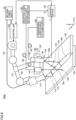
- Fig. 1 is an overall configuration diagram of a welding system 100 to which a welding inspection method according to the present embodiment is applied.
- This welding system 100 is used, for example, for inspection of a weld (weld bead) 106 in lap fillet joint of thin plates (base materials 102 and 104).
- Base materials 102 and 104 are, for example, galvanized steel plates each having a thickness approximately from 1 to 2 mm.
- a Y direction indicates a direction of movement of welding
- a Z direction indicates a direction normal to base materials 102 and 104
- an X direction indicates a direction orthogonal to the Y direction and the Z direction.
- Welding system 100 includes a robot manipulator 110, a welding torch 112, a wire 118, a welding power supply 120, and a controller 122.
- Robot manipulator 110 is an articulated manipulator such as a six-axis articulated manipulator. Robot manipulator 110 is controlled by controller 122 so as to weld base materials 102 and 104 with welding torch 112 at a set welding speed.
- Welding torch 112 supplies a welding wire and not-shown shielding gas (argon gas, carbon dioxide gas, or the like) toward a portion of joint between base materials 102 and 104.
- Welding torch 112 receives supply of a welding current from welding power supply 120 through wire 118, and generates an arc 114 between a tip end of the welding wire and the portion of joint between base materials 102 and 104.
- a non-consumable electrode tungsten or the like
- a filler filler metal
- arc welding by welding torch 112 may be a welding electrode type (such as MAG welding or MIG welding) using the welding wire, or may be a non-welding electrode type (such as TIG welding) with addition of the filler.
- Welding power supply 120 generates a welding voltage and a welding current in order to perform arc welding, and outputs the generated welding voltage and welding current to welding torch 112.
- Controller 122 includes a central processing unit (CPU), memories (a random access memory (RAM) and a read only memory (ROM)), and an input and output port for input and output of various signals (none of them are shown).
- the CPU develops a program stored in the ROM on the RAM and executes the same.
- Various types of processing executed by controller 122 are described in the program stored in the ROM.
- Controller 122 controls the operation of robot manipulator 110 and output of welding power supply 120 such that base materials 102 and 104 are welded by welding torch 112 at a set welding speed. At this time, controller 122 controls robot manipulator 110 such that a position of a welding inspection head 130 (which will be described later) is in the rear of welding torch 112 in the direction of movement of welding.
- controller 122 in coordination with a control device 164 that controls welding inspection head 130, exchanges various signals with control device 164. For example, controller 122 notifies control device 164 of start, stop, continuation, and a welding speed, of welding by welding torch 112. When controller 122 receives a defect detection signal indicating detection of an internal defect in the weld from control device 164, controller 122 can stop welding by welding torch 112 or change a welding condition.
- Welding system 100 further includes welding inspection head 130, optical fibers 142 and 148, a link 150, a transmission laser source 160, a reception laser source 162, and control device 164.
- Welding inspection head 130 includes a transmission laser light irradiation device 134 and a reception laser light probe 144.
- Transmission laser light irradiation device 134 and reception laser light probe 144 are attached to an attachment member 132.
- Attachment member 132 is coupled to robot manipulator 110 by link 150.
- Transmission laser light irradiation device 134 includes microchip laser 136, a scanning mechanism 138, and a photodetector 140.
- Microchip laser 136 is, for example, small solid-state laser using a YAG crystal, receives excitation light from transmission laser source 160 through optical fiber 142, and generates high-output pulsed laser light.
- Scanning mechanism 138 includes a mechanism that scans a position of irradiation with pulsed laser light generated by microchip laser 136 in two axes of a welding direction (Y direction) and a direction of width of welding (X direction).
- Scanning mechanism 138 includes, for example, a galvano mirror an angle of which is adjustable and a drive mechanism that drives the galvano mirror.
- the drive mechanism that drives scanning mechanism 138 is controlled by control device 164 such that an ultrasound transmission point group 154 irradiated with transmission laser light 152 (pulsed laser light) includes the entire area in the width direction (X direction) of weld bead 106.
- Photodetector 140 detects oscillation of transmission laser light 152 (pulsed laser light), and outputs a trigger signal Tr to control device 164 each time pulsed laser light is oscillated.
- Reception laser light probe 144 irradiates an ultrasound reception point 158, which is a predetermined position in the X direction on base material 104, with reception laser light 156 (reference light) received from reception laser source 162 through optical fiber 148.
- reception laser light probe 144 receives reflected light reflected from base material 104, of reception laser light 156 emitted to base material 104, and outputs reflected light to reception laser source 162 through optical fiber 148.
- Reception laser source 162 includes a laser interferometer, and outputs to reception laser light probe 144 through optical fiber 148, reception laser light 156 (reference light) to be emitted to base material 104. Then, reception laser source 162 receives from reception laser light probe 144, reflected light of reception laser light 156 from base material 104 received by reception laser light probe 144, and outputs to control device 164, a detection signal IS of coherent light including reference light and reflected light of reception laser light 156.
- the positions of irradiation with transmission laser light 152 and reception laser light 156 are desirably close to a position of welding (a molten pool 116).
- the positions of irradiation can be set to 20 to 30 mm behind molten pool 116 in the direction of movement of welding.
- control device 164 includes a CPU, memories (a RAM and a ROM), and an input and output port for input and output of various signals (none of them are shown).
- the CPU develops a program stored in the ROM on the RAM and executes the same.
- Various types of processing executed by control device 164 are described in the program stored in the ROM.
- Control device 164 measures detection signal IS of coherent light including reference light and reflected light of reception laser light 156 for a predetermined time period (for example, 10 ⁇ s), with trigger signal Tr from photodetector 140 indicating timing of oscillation of transmission laser light 152 (pulsed laser light) being defined as the reference. Control device 164 then measures intensity of ultrasound at ultrasound reception point 158 corresponding to trigger signal Tr, from measured detection signal IS of coherent light.
- Control device 164 measures the intensity of ultrasound at ultrasound reception point 158 as described above while the position of irradiation (ultrasound transmission point) with transmission laser light 152 is scanned in the direction of width (X direction) of weld 106. When measurement corresponding to one scan ends, control device 164 determines whether or not there is an internal defect produced in weld 106 based on a degree of attenuation of ultrasound (reflected ultrasound) that is reflected by a lower surface of a lower plate (base material 104) and reaches ultrasound reception point 158.
- a laser ultrasonic method is used to detect the internal defect in weld 106.
- ultrasound is generated in the inside of a detection target by irradiation of weld 106 to be inspected with transmission laser light 152, and surface vibration in accordance with intensity of ultrasound at ultrasound reception point 158 irradiated with reception laser light 156 is detected based on coherent light including reference light and reflected light of reception laser light 156.
- Whether or not there is an internal defect in weld 106 is then determined based on a detection difference between a case where there is no internal defect in weld 106 and a case where there is an internal defect.
- Figs. 2 and 3 are diagrams illustrating principles of detection of the internal defect in the weld by welding system 100.
- Fig. 2 illustrates a state where there is no defect in weld 106
- Fig. 3 illustrates a state where there is an internal defect (a blowhole or the like) in weld 106.
- an area including weld 106 is irradiated with transmission laser light 152 from above (Z direction), and ultrasound is excited at the position of irradiation with laser light.
- Generated ultrasound passes through weld 106, is reflected by a lower surface 105 of base material 104 on a lower side, and reaches an upper surface of base material 104.
- Intensity of ultrasound at the position of irradiation (ultrasound reception point 158) with reception laser light 156 is measured by measurement with reception laser light 156 (interference measurement using the laser interferometer), of micro vibration generated by this reached ultrasound at the surface of base material 104.
- the position of irradiation with transmission laser light 152 is scanned in the X direction by scanning mechanism 138.
- An ultrasound transmission point group 154 indicated by a ⁇ mark indicates the position of irradiation with transmission laser light 152 which is pulsed laser light. After measurement at a certain position of irradiation ends, the next position of irradiation with transmission laser light 152 is scanned, and measurement at that position of irradiation is conducted.
- the position of irradiation with reception laser light 156 is fixed in the X direction of base material 104.
- Ultrasound reception point 158 indicated by a o mark indicates the position of irradiation with reception laser light 156.
- a distance between each point in ultrasound transmission point group 154 and ultrasound reception point 158 is longer in the X direction, a time period of propagation of ultrasound from each point in ultrasound transmission point group 154 to ultrasound reception point 158 is longer, and intensity of ultrasound (micro vibration at the surface) at ultrasound reception point 158 also decreases due to diffusion attenuation.
- Fig. 4 is a diagram showing relation between the position of irradiation with transmission laser light 152 and time of arrival of ultrasound at ultrasound reception point 158.
- the horizontal axis represents the position of irradiation with transmission laser light 152 (the position of the ultrasound transmission point) in the X direction, and a larger value indicates a longer distance from ultrasound reception point 158.
- the vertical axis represents time from emission of transmission laser light 152 (generation of ultrasound at the ultrasound transmission point) to arrival of ultrasound at ultrasound reception point 158.
- a line L1 indicates time of arrival of ultrasound (surface wave) transmitted through weld 106 over the surface of base material 104.
- a line L2 indicates time of arrival of ultrasound (reflected wave) that passes through weld 106 from the ultrasound transmission point and is reflected by lower surface 105 of base material 104.
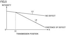
- Fig. 5 is a diagram showing relation between the position of the ultrasound transmission point and intensity of ultrasound at the ultrasound reception point.
- the horizontal axis represents the position of the ultrasound transmission point.
- the vertical axis indicates intensity of reflected waves (line L2) in Fig. 4 at the ultrasound reception point.
- a line L3 indicates intensity of reflected waves (line L2) at the ultrasound reception point when there is no internal defect in weld 106.
- signal intensity is attenuated by diffusion attenuation.
- a line L4 indicates intensity of reflected waves (line L2 in Fig. 4 ) at the ultrasound reception point when there is an internal defect (a blowhole or the like) in weld 106.
- an internal defect a blowhole or the like
- reflected waves reaching the ultrasound reception point pass through the internal defect produced in weld 106.
- intensity of reflected waves (line L4) at the ultrasound reception point is lower than intensity of reflected waves (line L3) when there is no internal defect. That is, at the ultrasound reception point, the degree of attenuation of reflected waves when an internal defect is produced becomes higher than that when there is no internal defect.
- Fig. 6 is a diagram showing a method of determining whether or not there is an internal defect in weld 106. Whether or not there is an internal defect in weld 106 is determined based on magnitude of the degree of attenuation corresponding to the position of the ultrasound transmission point, with respect to intensity of reflected waves at the ultrasound reception point. That is, it is determined that there is no internal defect when the degree of attenuation in accordance with the position of the ultrasound transmission point is smaller than a predetermined threshold value, and it is determined that there is an internal defect produced in weld 106 to be inspected when the degree of attenuation is larger than the threshold value.
- the threshold value is set as appropriate to a value with which distinction as to whether or not there is an internal defect can be made, in an evaluation test or the like in advance.
- Slag refers to an oxide of silicon (Si), manganese (Mn), iron (Fe), or the like exposed at the surface of the weld.
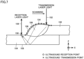
- Fig. 7 is a diagram showing a state of attachment like a film, of an impurity (slag) 108 to the surface of weld 106.
- impurity 108 With impurity 108 being attached to the surface of weld 106, impurity 108 is irradiated with transmission laser light in welding inspection, which may interfere with generation of ultrasound. Consequently, there is a concern that the impurity becomes a factor for defective welding inspection.
- Welding system 100 further includes a surface treatment apparatus 200 as shown in Fig. 1 .
- Surface treatment apparatus 200 is a tool for removal of impurity 108 attached to the surface of weld 106.
- Surface treatment apparatus 200 is coupled to welding inspection head 130.
- surface treatment apparatus 200 is coupled to welding inspection head 130 by a link 210.
- Surface treatment apparatus 200 includes a removal mechanism (a brush or the like) that comes in contact with the surface of weld 106 for mechanical removal at the surface of weld 106. Impurity 108 attached to the surface of weld 106 is removed by this removal mechanism.
- a method of removing the impurity is not limited to the method of mechanical removal at the surface of weld 106.
- surface treatment apparatus 200 may be implemented by a laser light irradiation device, output from which is adjusted to remove impurity 108 attached to the surface of weld 106. In this case, by irradiation of the surface of weld 106 with laser from surface treatment apparatus 200, impurity 108 attached to the surface of weld 106 can contactlessly be removed by impact produced by laser ablation.
- control device 164 performs processing in a first step to a fourth step below in this order.
- the position of surface treatment apparatus 200 is adjusted in advance such that the position of removal by surface treatment apparatus 200 is in the rear of molten pool 116 (the position of welding by welding torch 112) in the direction of movement of welding and in front of ultrasound transmission point group 154 (the position of irradiation with transmission laser light 152) in the direction of movement of welding.
- the impurity at the surface of weld 106 can be removed by surface treatment apparatus 200 before irradiation of the surface of weld 106 with transmission laser light 152.
- Fig. 8 is a flowchart showing an exemplary procedure of processing in in-process welding inspection during welding in control device 164 according to the present embodiment.
- Control device 164 activates surface treatment apparatus 200 to have the impurity at the surface of weld 106 removed (step S102).
- welding inspection head 130 also moves together with welding torch 112 in the direction of movement of welding (Y direction).
- Surface treatment apparatus 200 is coupled to welding inspection head 130, and furthermore, the position of removal by surface treatment apparatus 200 is adjusted to the position in the rear of molten pool 116 in the direction of movement of welding and in front of ultrasound transmission point group 154 in the direction of movement of welding as described above. Therefore, at the position to be irradiated with transmission laser light 152 in a subsequent step, the impurity has already been removed.
- Processing in step S102 corresponds to the "first step" described above.
- Control device 164 then controls scanning mechanism 138 so as to irradiate a predetermined position in the X direction of weld 106 with transmission laser light 152 (step S110).
- the position in the X direction of each point of irradiation with transmission laser light 152 in one scan is determined in advance, and a predetermined number of (for example, twenty) positions of irradiation are determined in an area including weld 106.
- Processing in step S110 corresponds to the "second step" described above.
- Oscillation of (irradiation with) transmission laser light 152 (pulsed laser light) is then detected by photodetector 140, and trigger signal Tr indicating start of detection of ultrasound corresponding to this pulse irradiation is transmitted from photodetector 140 to control device 164 (step S115).
- control device 164 measures for a predetermined time period (for example, 10 ⁇ s), intensity of ultrasound at ultrasound reception point 158 based on coherent light of reception laser light 156 obtained by the laser interferometer (step S120). Processing in steps S115 and S120 corresponds to the "third step" described above.
- Control device 164 determines whether measurement corresponding to one scan with transmission laser light 152 has been completed (step S125). Specifically, whether measurement has been completed at all predetermined positions of irradiation in the X direction is determined. When measurement corresponding to one scan has not been completed (NO in step S125), control device 164 updates the position of irradiation with transmission laser light 152 to the next position (step S130). Then, the process returns to step S110.
- control device 164 determines whether or not there is an internal defect in weld 106 corresponding to a range of one scan, based on a result of measurement corresponding to one scan (step S150).
- control device 164 extracts from the result of measurement corresponding to one scan, a signal of reflected waves (ultrasound that is reflected by the lower surface of base material 104 and reaches ultrasound reception point 158) reflected at the position of irradiation (ultrasound reception point) with reception laser light 156 for each position of irradiation (ultrasound transmission point) with transmission laser light 152 scanned in the X direction. Control device 164 then calculates the degree of attenuation of ultrasound in accordance with the position of irradiation with (position of transmission of) transmission laser light 152 for that extracted reflected wave signal, and determines whether or not the calculated degree of attenuation is larger than the threshold value.
- This threshold value is set as appropriate to a value that allows distinction as to whether or not there is an internal defect, in the evaluation test in advance.
- control device 164 determines that there is an internal defect in weld bead 106 corresponding to the range of one scan. Processing in step S150 corresponds to the "fourth step" described above.
- control device 164 When it is determined in step S150 that there is an internal defect (YES in step S150), control device 164 outputs a defect detection signal indicating detection of a defect in weld 106 to controller 122 on a robot manipulator side (step S152). Thereafter, control device 164 has the process make transition to step S160.
- control device 164 When it is not determined in step S150 that there is an internal defect (NO in step S150), on the other hand, control device 164 has the process make transition to step S160 without performing processing in step S152.
- Control device 164 determines whether welding is to be continued, based on the signal from controller 122 indicating whether or not welding should continue (step S160). When welding is to be continued (YES in step S160), control device 164 makes transition to measurement in a next measurement line (step S165), and has the process return to step S110.
- control device 164 quits the process of welding inspection.
- the welding inspection method includes removing the impurity at the surface of weld 106 with surface treatment apparatus 200 (first step), irradiating the surface of weld 106 from which the impurity has been removed with transmission laser light (second step), detecting reflected ultrasound reflected by lower surface 105 of base material 104 (third step), and determining whether or not there is an internal defect in weld 106 based on a result of detection of reflected ultrasound (fourth step).
- dedicated surface treatment apparatus 200 for removal of impurity 108 attached to the surface of weld 106 is provided. Without dedicated surface treatment apparatus 200, however, impurity 108 attached to the surface of weld 106 may be removed with transmission laser light.
- Fig. 9 is an overall configuration diagram of a welding system 100A to which the welding inspection method according to the present second modification is applied.
- This welding system 100A is configured by removal of surface treatment apparatus 200 and link 210 from welding system 100 described above.
- scanning mechanism 138 (the galvano mirror or the like) for scanning with transmission laser light in transmission laser light irradiation device 134
- scanning mechanism 138 is controlled to remove the impurity attached to the surface of weld 106 by irradiation of the surface of weld 106 with transmission laser light 152a, and controlled to irradiate the surface of weld 106 from which the impurity has been removed with transmission laser light 152.
- Transmission laser light can thus be used for removal of the impurity. Consequently, without dedicated surface treatment apparatus 200, the internal defect in weld 106 can appropriately be detected.
- Fig. 10 is a flowchart showing an exemplary procedure of processing in in-process welding inspection during welding by control device 164 according to the present first modification.
- the flowchart in Fig. 10 includes step S102A in place of step S102 in Fig. 8 described above.
- control device 164 controls scanning mechanism 138 to remove the impurity attached to the surface to be scanned in next one scan, by irradiation with transmission laser light 152a, of the surface of weld 106 to be scanned in next one scan (step S102A).
- Control device 164 then conducts welding inspection by irradiation of the surface corresponding to one scan with transmission laser light 152 (steps 5110 to S152).
- control device 164 makes transition to measurement in the next measurement line (step S165) and has the process return to step S102A.
- control device 164 quits the process of welding inspection.
- impurity 108 attached to the surface of weld 106 may be removed by irradiation of the surface of weld 106 with transmission laser light 152.
- surface treatment apparatus 200 constantly removes the impurity without verification as to whether or not impurity 108 is attached to the surface of weld 106.
- surface treatment apparatus 200 may remove the impurity only when whether or not impurity 108 is attached to the surface of weld 106 is verified in advance and then a result of verification indicating attachment of impurity 108 is obtained.
- first welding inspection is conducted without removal of the impurity by surface treatment apparatus 200, and whether or not the impurity is attached to the surface of weld 106 is estimated based on the result of the first welding inspection.
- the welding inspection ends.
- surface treatment apparatus 200 removes the impurity and second welding inspection is conducted. According to such a modification, removal of the impurity by surface treatment apparatus 200 even in the case of attachment of no impurity 108 to the surface of weld 106 can more readily be avoided. Consequently, the welding inspection can efficiently be conducted.
- ultrasound reception point 158 is irradiated with reception laser light from reception laser light probe 144 and reflected waves are contactlessly detected in the welding inspection method according to the embodiment described above, the method of detecting reflected waves is not necessarily limited to a contactless method.
- a device that is in contact with ultrasound reception point 158 to detect reflected waves at ultrasound reception point 158 may be arranged to detect reflected waves.
- ultrasound to be detected should only be ultrasound excited by transmission laser light, and it is not necessarily limited to ultrasound reflected by lower surface 105 of base material 104.
- surface treatment apparatus 200 is coupled to welding inspection head 130 in welding system 100 according to the embodiment described above, surface treatment apparatus 200 is not necessarily limited to the surface treatment apparatus coupled to welding inspection head 130. In other words, welding inspection head 130 and surface treatment apparatus 200 may be mounted on robots different from each other.
Landscapes
- Chemical & Material Sciences (AREA)
- Health & Medical Sciences (AREA)
- Life Sciences & Earth Sciences (AREA)
- Physics & Mathematics (AREA)
- Engineering & Computer Science (AREA)
- Biochemistry (AREA)
- General Health & Medical Sciences (AREA)
- General Physics & Mathematics (AREA)
- Immunology (AREA)
- Pathology (AREA)
- Analytical Chemistry (AREA)
- Medicinal Chemistry (AREA)
- Food Science & Technology (AREA)
- Mechanical Engineering (AREA)
- Quality & Reliability (AREA)
- Optics & Photonics (AREA)
- Crystallography & Structural Chemistry (AREA)
- Investigating Or Analyzing Materials By The Use Of Ultrasonic Waves (AREA)
- Arc Welding In General (AREA)
- Laser Beam Processing (AREA)
Abstract
Description
- The present disclosure relates to a welding inspection method.
- For example,
Japanese Patent No. 5651533 - In the welding inspection method disclosed in
Japanese Patent No. 5651533 - Therefore, an object of the present disclosure is to provide a welding inspection method that allows appropriate detection of an internal defect in a weld even when an impurity is attached to a surface of the weld.
- (Clause 1) A welding inspection method according to the present disclosure is a welding inspection method of inspecting a weld. The welding inspection method includes removing an impurity at a surface of the weld, irradiating the surface of the weld from which the impurity has been removed with transmission laser light for excitation of ultrasound in inside of a detection target, detecting ultrasound excited by transmission laser light, and determining whether there is an internal defect in the weld based on a result of detection of ultrasound.
- According to this welding inspection method, the impurity attached to the surface of the weld is removed before irradiation of the surface of the weld with transmission laser light. Therefore, even when the impurity is attached to the surface of the weld, the internal defect in the weld can appropriately be detected.
- (Clause 2) In the welding inspection method described in Clause 1, the removing an impurity includes removing the impurity by irradiating the surface of the weld with transmission laser light.
- (Clause 3) In the welding inspection method described in Clause 1, the detecting ultrasound includes irradiating a predetermined position on the detection target where reflected ultrasound reflected by a lower surface of a base material of the detection target can be detected, with reception laser light for detection of reflected ultrasound.
- (Clause 4) The welding inspection method described in Clause 1 is performed in-process while welding is being performed.
- The foregoing and other objects, features, aspects and advantages of this invention will become more apparent from the following detailed description of this invention when taken in conjunction with the accompanying drawings.
-
-
Fig. 1 is an overall configuration diagram (No. 1) of a welding system to which a welding inspection method is applied. -
Fig. 2 is a diagram (No. 1) illustrating principles of detection of an internal defect in a weld. -
Fig. 3 is a diagram (No. 2) illustrating principles of detection of the internal defect in the weld. -
Fig. 4 is a diagram showing relation between a position of irradiation with transmission laser light and a time of arrival of ultrasound at an ultrasound reception point. -
Fig. 5 is a diagram showing relation between a position of an ultrasound transmission point and intensity of ultrasound at an ultrasound reception point. -
Fig. 6 is a diagram illustrating a method of determining whether or not there is an internal defect in the weld. -
Fig. 7 is a diagram showing a state of attachment like a film, of an impurity (slag) to a surface of the weld. -
Fig. 8 is a flowchart (No. 1) showing an exemplary procedure of processing in a control device. -
Fig. 9 is an overall configuration diagram (No. 2) of a welding system to which the welding inspection method is applied. -
Fig. 10 is a flowchart (No. 2) showing an exemplary procedure of processing in the control device. - An embodiment of the present disclosure will be described in detail below with reference to the drawings. The same or corresponding elements in the drawings have the same reference characters allotted and description thereof will not be repeated.
-
Fig. 1 is an overall configuration diagram of awelding system 100 to which a welding inspection method according to the present embodiment is applied. Thiswelding system 100 is used, for example, for inspection of a weld (weld bead) 106 in lap fillet joint of thin plates (base materials 102 and 104).Base materials base materials -
Welding system 100 includes arobot manipulator 110, awelding torch 112, awire 118, awelding power supply 120, and acontroller 122. -
Robot manipulator 110 is an articulated manipulator such as a six-axis articulated manipulator.Robot manipulator 110 is controlled bycontroller 122 so as toweld base materials welding torch 112 at a set welding speed. -
Welding torch 112 supplies a welding wire and not-shown shielding gas (argon gas, carbon dioxide gas, or the like) toward a portion of joint betweenbase materials Welding torch 112 receives supply of a welding current fromwelding power supply 120 throughwire 118, and generates anarc 114 between a tip end of the welding wire and the portion of joint betweenbase materials - Instead of the welding wire, a non-consumable electrode (tungsten or the like) may be used while a filler (filler metal) that forms weld metal is added. That is, arc welding by
welding torch 112 may be a welding electrode type (such as MAG welding or MIG welding) using the welding wire, or may be a non-welding electrode type (such as TIG welding) with addition of the filler. -
Welding power supply 120 generates a welding voltage and a welding current in order to perform arc welding, and outputs the generated welding voltage and welding current to weldingtorch 112. -
Controller 122 includes a central processing unit (CPU), memories (a random access memory (RAM) and a read only memory (ROM)), and an input and output port for input and output of various signals (none of them are shown). The CPU develops a program stored in the ROM on the RAM and executes the same. Various types of processing executed bycontroller 122 are described in the program stored in the ROM. -
Controller 122 controls the operation ofrobot manipulator 110 and output ofwelding power supply 120 such thatbase materials welding torch 112 at a set welding speed. At this time,controller 122 controlsrobot manipulator 110 such that a position of a welding inspection head 130 (which will be described later) is in the rear ofwelding torch 112 in the direction of movement of welding. - In addition,
controller 122, in coordination with acontrol device 164 that controlswelding inspection head 130, exchanges various signals withcontrol device 164. For example,controller 122 notifiescontrol device 164 of start, stop, continuation, and a welding speed, of welding bywelding torch 112. Whencontroller 122 receives a defect detection signal indicating detection of an internal defect in the weld fromcontrol device 164,controller 122 can stop welding bywelding torch 112 or change a welding condition. -
Welding system 100 further includeswelding inspection head 130,optical fibers link 150, atransmission laser source 160, areception laser source 162, andcontrol device 164. -
Welding inspection head 130 includes a transmission laserlight irradiation device 134 and a receptionlaser light probe 144. Transmission laserlight irradiation device 134 and receptionlaser light probe 144 are attached to anattachment member 132.Attachment member 132 is coupled torobot manipulator 110 bylink 150. - Transmission laser
light irradiation device 134 includesmicrochip laser 136, ascanning mechanism 138, and aphotodetector 140.Microchip laser 136 is, for example, small solid-state laser using a YAG crystal, receives excitation light fromtransmission laser source 160 throughoptical fiber 142, and generates high-output pulsed laser light. -
Scanning mechanism 138 includes a mechanism that scans a position of irradiation with pulsed laser light generated bymicrochip laser 136 in two axes of a welding direction (Y direction) and a direction of width of welding (X direction).Scanning mechanism 138 includes, for example, a galvano mirror an angle of which is adjustable and a drive mechanism that drives the galvano mirror. During welding inspection, the drive mechanism that drivesscanning mechanism 138 is controlled bycontrol device 164 such that an ultrasoundtransmission point group 154 irradiated with transmission laser light 152 (pulsed laser light) includes the entire area in the width direction (X direction) ofweld bead 106. -
Photodetector 140 detects oscillation of transmission laser light 152 (pulsed laser light), and outputs a trigger signal Tr to controldevice 164 each time pulsed laser light is oscillated. - Reception
laser light probe 144 irradiates anultrasound reception point 158, which is a predetermined position in the X direction onbase material 104, with reception laser light 156 (reference light) received fromreception laser source 162 throughoptical fiber 148. In addition, receptionlaser light probe 144 receives reflected light reflected frombase material 104, ofreception laser light 156 emitted tobase material 104, and outputs reflected light toreception laser source 162 throughoptical fiber 148. -
Reception laser source 162 includes a laser interferometer, and outputs to receptionlaser light probe 144 throughoptical fiber 148, reception laser light 156 (reference light) to be emitted tobase material 104. Then,reception laser source 162 receives from receptionlaser light probe 144, reflected light ofreception laser light 156 frombase material 104 received by receptionlaser light probe 144, and outputs tocontrol device 164, a detection signal IS of coherent light including reference light and reflected light ofreception laser light 156. - In consideration of in-process defect detection during welding, the positions of irradiation with
transmission laser light 152 andreception laser light 156 are desirably close to a position of welding (a molten pool 116). For example, the positions of irradiation can be set to 20 to 30 mm behindmolten pool 116 in the direction of movement of welding. - Similarly to
controller 122,control device 164 includes a CPU, memories (a RAM and a ROM), and an input and output port for input and output of various signals (none of them are shown). The CPU develops a program stored in the ROM on the RAM and executes the same. Various types of processing executed bycontrol device 164 are described in the program stored in the ROM. -
Control device 164 measures detection signal IS of coherent light including reference light and reflected light ofreception laser light 156 for a predetermined time period (for example, 10 µs), with trigger signal Tr fromphotodetector 140 indicating timing of oscillation of transmission laser light 152 (pulsed laser light) being defined as the reference.Control device 164 then measures intensity of ultrasound atultrasound reception point 158 corresponding to trigger signal Tr, from measured detection signal IS of coherent light. -
Control device 164 measures the intensity of ultrasound atultrasound reception point 158 as described above while the position of irradiation (ultrasound transmission point) withtransmission laser light 152 is scanned in the direction of width (X direction) ofweld 106. When measurement corresponding to one scan ends,control device 164 determines whether or not there is an internal defect produced inweld 106 based on a degree of attenuation of ultrasound (reflected ultrasound) that is reflected by a lower surface of a lower plate (base material 104) and reachesultrasound reception point 158. - In this
welding system 100, a laser ultrasonic method is used to detect the internal defect inweld 106. Specifically, ultrasound is generated in the inside of a detection target by irradiation ofweld 106 to be inspected withtransmission laser light 152, and surface vibration in accordance with intensity of ultrasound atultrasound reception point 158 irradiated withreception laser light 156 is detected based on coherent light including reference light and reflected light ofreception laser light 156. Whether or not there is an internal defect inweld 106 is then determined based on a detection difference between a case where there is no internal defect inweld 106 and a case where there is an internal defect. -
Figs. 2 and3 are diagrams illustrating principles of detection of the internal defect in the weld by weldingsystem 100.Fig. 2 illustrates a state where there is no defect inweld 106, andFig. 3 illustrates a state where there is an internal defect (a blowhole or the like) inweld 106. - With reference to
Fig. 2 , in thiswelding system 100, anarea including weld 106 is irradiated withtransmission laser light 152 from above (Z direction), and ultrasound is excited at the position of irradiation with laser light. Generated ultrasound passes throughweld 106, is reflected by alower surface 105 ofbase material 104 on a lower side, and reaches an upper surface ofbase material 104. Intensity of ultrasound at the position of irradiation (ultrasound reception point 158) withreception laser light 156 is measured by measurement with reception laser light 156 (interference measurement using the laser interferometer), of micro vibration generated by this reached ultrasound at the surface ofbase material 104. - The position of irradiation with
transmission laser light 152 is scanned in the X direction by scanningmechanism 138. An ultrasoundtransmission point group 154 indicated by a × mark indicates the position of irradiation withtransmission laser light 152 which is pulsed laser light. After measurement at a certain position of irradiation ends, the next position of irradiation withtransmission laser light 152 is scanned, and measurement at that position of irradiation is conducted. - The position of irradiation with
reception laser light 156 is fixed in the X direction ofbase material 104.Ultrasound reception point 158 indicated by a o mark indicates the position of irradiation withreception laser light 156. As a distance between each point in ultrasoundtransmission point group 154 andultrasound reception point 158 is longer in the X direction, a time period of propagation of ultrasound from each point in ultrasoundtransmission point group 154 toultrasound reception point 158 is longer, and intensity of ultrasound (micro vibration at the surface) atultrasound reception point 158 also decreases due to diffusion attenuation. - With reference to
Fig. 3 , when there is adefect 107 such as a blowhole inweld 106, scattering attenuation in addition to diffusion attenuation also occurs atdefect 107. Therefore, intensity ofultrasound 155 reachingultrasound reception point 158 is lower (attenuation is larger) than that when there is nodefect 107. Therefore, whether or not there is adefect 107 inweld 106 can be determined by capturing a degree of attenuation of ultrasound reachingultrasound reception point 158. -
Fig. 4 is a diagram showing relation between the position of irradiation withtransmission laser light 152 and time of arrival of ultrasound atultrasound reception point 158. InFig. 4 , the horizontal axis represents the position of irradiation with transmission laser light 152 (the position of the ultrasound transmission point) in the X direction, and a larger value indicates a longer distance fromultrasound reception point 158. The vertical axis represents time from emission of transmission laser light 152 (generation of ultrasound at the ultrasound transmission point) to arrival of ultrasound atultrasound reception point 158. - In
Fig. 4 , a line L1 indicates time of arrival of ultrasound (surface wave) transmitted throughweld 106 over the surface ofbase material 104. A line L2 indicates time of arrival of ultrasound (reflected wave) that passes throughweld 106 from the ultrasound transmission point and is reflected bylower surface 105 ofbase material 104. - Since time of arrival of surface wave is not affected by whether or not there is
defect 107, distinction as to whether ultrasound detected at the ultrasound reception point is surface wave or ultrasound (reflected wave) reflected bylower surface 105 ofbase material 104 can be made based on relation between the position of the ultrasound transmission point and the time of arrival. -
Fig. 5 is a diagram showing relation between the position of the ultrasound transmission point and intensity of ultrasound at the ultrasound reception point. InFig. 5 , similarly toFig. 4 , the horizontal axis represents the position of the ultrasound transmission point. The vertical axis indicates intensity of reflected waves (line L2) inFig. 4 at the ultrasound reception point. - In
Fig. 5 , a line L3 indicates intensity of reflected waves (line L2) at the ultrasound reception point when there is no internal defect inweld 106. As a value of the position of the ultrasound transmission point is larger (as the distance from the ultrasound reception point is longer), signal intensity is attenuated by diffusion attenuation. - A line L4 indicates intensity of reflected waves (line L2 in
Fig. 4 ) at the ultrasound reception point when there is an internal defect (a blowhole or the like) inweld 106. In a range where the position of the ultrasound transmission point is farther than a position X1 shown inFig. 5 , reflected waves reaching the ultrasound reception point pass through the internal defect produced inweld 106. At this time, scattering attenuation at the internal defect in addition to diffusion attenuation also occurs, and hence intensity of reflected waves (line L4) at the ultrasound reception point is lower than intensity of reflected waves (line L3) when there is no internal defect. That is, at the ultrasound reception point, the degree of attenuation of reflected waves when an internal defect is produced becomes higher than that when there is no internal defect. -
Fig. 6 is a diagram showing a method of determining whether or not there is an internal defect inweld 106. Whether or not there is an internal defect inweld 106 is determined based on magnitude of the degree of attenuation corresponding to the position of the ultrasound transmission point, with respect to intensity of reflected waves at the ultrasound reception point. That is, it is determined that there is no internal defect when the degree of attenuation in accordance with the position of the ultrasound transmission point is smaller than a predetermined threshold value, and it is determined that there is an internal defect produced inweld 106 to be inspected when the degree of attenuation is larger than the threshold value. The threshold value is set as appropriate to a value with which distinction as to whether or not there is an internal defect can be made, in an evaluation test or the like in advance. - An impurity such as slag produced during welding may be attached to the surface of
weld 106. Slag refers to an oxide of silicon (Si), manganese (Mn), iron (Fe), or the like exposed at the surface of the weld. -
Fig. 7 is a diagram showing a state of attachment like a film, of an impurity (slag) 108 to the surface ofweld 106. Withimpurity 108 being attached to the surface ofweld 106,impurity 108 is irradiated with transmission laser light in welding inspection, which may interfere with generation of ultrasound. Consequently, there is a concern that the impurity becomes a factor for defective welding inspection. -
Welding system 100 according to the present embodiment further includes asurface treatment apparatus 200 as shown inFig. 1 .Surface treatment apparatus 200 is a tool for removal ofimpurity 108 attached to the surface ofweld 106.Surface treatment apparatus 200 is coupled to weldinginspection head 130. In the example shown inFig. 1 ,surface treatment apparatus 200 is coupled to weldinginspection head 130 by alink 210. -
Surface treatment apparatus 200 according to the present embodiment includes a removal mechanism (a brush or the like) that comes in contact with the surface ofweld 106 for mechanical removal at the surface ofweld 106.Impurity 108 attached to the surface ofweld 106 is removed by this removal mechanism. A method of removing the impurity is not limited to the method of mechanical removal at the surface ofweld 106. For example,surface treatment apparatus 200 may be implemented by a laser light irradiation device, output from which is adjusted to removeimpurity 108 attached to the surface ofweld 106. In this case, by irradiation of the surface ofweld 106 with laser fromsurface treatment apparatus 200,impurity 108 attached to the surface ofweld 106 can contactlessly be removed by impact produced by laser ablation. - In welding inspection,
control device 164 performs processing in a first step to a fourth step below in this order. - (First Step) The impurity at the surface of
weld 106 is removed withsurface treatment apparatus 200. - (Second Step) The surface of
weld 106 from which the impurity has been removed is irradiated with transmission laser light. - (Third Step) Ultrasound (reflected waves) reflected by
lower surface 105 ofbase material 104 is detected. - (Fourth Step) Whether or not there is an internal defect in
weld 106 is determined based on a result of detection of reflected waves. - As shown in
Fig. 1 , the position ofsurface treatment apparatus 200 according to the present embodiment is adjusted in advance such that the position of removal bysurface treatment apparatus 200 is in the rear of molten pool 116 (the position of welding by welding torch 112) in the direction of movement of welding and in front of ultrasound transmission point group 154 (the position of irradiation with transmission laser light 152) in the direction of movement of welding. Thus, in in-process welding inspection during welding, the impurity at the surface ofweld 106 can be removed bysurface treatment apparatus 200 before irradiation of the surface ofweld 106 withtransmission laser light 152. -
Fig. 8 is a flowchart showing an exemplary procedure of processing in in-process welding inspection during welding incontrol device 164 according to the present embodiment. -
Control device 164 activatessurface treatment apparatus 200 to have the impurity at the surface ofweld 106 removed (step S102). During welding,welding inspection head 130 also moves together withwelding torch 112 in the direction of movement of welding (Y direction).Surface treatment apparatus 200 is coupled to weldinginspection head 130, and furthermore, the position of removal bysurface treatment apparatus 200 is adjusted to the position in the rear ofmolten pool 116 in the direction of movement of welding and in front of ultrasoundtransmission point group 154 in the direction of movement of welding as described above. Therefore, at the position to be irradiated withtransmission laser light 152 in a subsequent step, the impurity has already been removed. Processing in step S102 corresponds to the "first step" described above. -
Control device 164 then controlsscanning mechanism 138 so as to irradiate a predetermined position in the X direction ofweld 106 with transmission laser light 152 (step S110). The position in the X direction of each point of irradiation withtransmission laser light 152 in one scan is determined in advance, and a predetermined number of (for example, twenty) positions of irradiation are determined in anarea including weld 106. Processing in step S110 corresponds to the "second step" described above. - Oscillation of (irradiation with) transmission laser light 152 (pulsed laser light) is then detected by
photodetector 140, and trigger signal Tr indicating start of detection of ultrasound corresponding to this pulse irradiation is transmitted fromphotodetector 140 to control device 164 (step S115). - With trigger signal Tr being defined as the reference,
control device 164 measures for a predetermined time period (for example, 10 µs), intensity of ultrasound atultrasound reception point 158 based on coherent light ofreception laser light 156 obtained by the laser interferometer (step S120). Processing in steps S115 and S120 corresponds to the "third step" described above. -
Control device 164 then determines whether measurement corresponding to one scan withtransmission laser light 152 has been completed (step S125). Specifically, whether measurement has been completed at all predetermined positions of irradiation in the X direction is determined. When measurement corresponding to one scan has not been completed (NO in step S125),control device 164 updates the position of irradiation withtransmission laser light 152 to the next position (step S130). Then, the process returns to step S110. - When it is determined in step S125 that measurement corresponding to one scan with
transmission laser light 152 has been completed (YES in step S125),control device 164 determines whether or not there is an internal defect inweld 106 corresponding to a range of one scan, based on a result of measurement corresponding to one scan (step S150). - Specifically,
control device 164 extracts from the result of measurement corresponding to one scan, a signal of reflected waves (ultrasound that is reflected by the lower surface ofbase material 104 and reaches ultrasound reception point 158) reflected at the position of irradiation (ultrasound reception point) withreception laser light 156 for each position of irradiation (ultrasound transmission point) withtransmission laser light 152 scanned in the X direction.Control device 164 then calculates the degree of attenuation of ultrasound in accordance with the position of irradiation with (position of transmission of)transmission laser light 152 for that extracted reflected wave signal, and determines whether or not the calculated degree of attenuation is larger than the threshold value. This threshold value is set as appropriate to a value that allows distinction as to whether or not there is an internal defect, in the evaluation test in advance. When the degree of attenuation is larger than the threshold value,control device 164 determines that there is an internal defect inweld bead 106 corresponding to the range of one scan. Processing in step S150 corresponds to the "fourth step" described above. - When it is determined in step S150 that there is an internal defect (YES in step S150),
control device 164 outputs a defect detection signal indicating detection of a defect inweld 106 tocontroller 122 on a robot manipulator side (step S152). Thereafter,control device 164 has the process make transition to step S160. - When it is not determined in step S150 that there is an internal defect (NO in step S150), on the other hand,
control device 164 has the process make transition to step S160 without performing processing in step S152. -
Control device 164 then determines whether welding is to be continued, based on the signal fromcontroller 122 indicating whether or not welding should continue (step S160). When welding is to be continued (YES in step S160),control device 164 makes transition to measurement in a next measurement line (step S165), and has the process return to step S110. - When it is determined in step S160 that welding is to be stopped based on the signal from controller 122 (NO in step S160), on the other hand,
control device 164 quits the process of welding inspection. - As set forth above, the welding inspection method according to the present embodiment includes removing the impurity at the surface of
weld 106 with surface treatment apparatus 200 (first step), irradiating the surface ofweld 106 from which the impurity has been removed with transmission laser light (second step), detecting reflected ultrasound reflected bylower surface 105 of base material 104 (third step), and determining whether or not there is an internal defect inweld 106 based on a result of detection of reflected ultrasound (fourth step). - According to such a welding inspection method, even when the impurity produced during welding is attached to the surface of
weld 106, the impurity is removed before irradiation of the surface ofweld 106 with transmission laser light. Therefore, even when the impurity produced during welding is attached to the surface ofweld 106, the internal defect inweld 106 can appropriately be detected. - In the embodiment described above, an example where dedicated
surface treatment apparatus 200 for removal ofimpurity 108 attached to the surface ofweld 106 is provided is described. Without dedicatedsurface treatment apparatus 200, however,impurity 108 attached to the surface ofweld 106 may be removed with transmission laser light. -
Fig. 9 is an overall configuration diagram of awelding system 100A to which the welding inspection method according to the present second modification is applied. Thiswelding system 100A is configured by removal ofsurface treatment apparatus 200 and link 210 from weldingsystem 100 described above. - In this
welding system 100A, in view of provision of scanning mechanism 138 (the galvano mirror or the like) for scanning with transmission laser light in transmission laserlight irradiation device 134,scanning mechanism 138 is controlled to remove the impurity attached to the surface ofweld 106 by irradiation of the surface ofweld 106 withtransmission laser light 152a, and controlled to irradiate the surface ofweld 106 from which the impurity has been removed withtransmission laser light 152. Transmission laser light can thus be used for removal of the impurity. Consequently, without dedicatedsurface treatment apparatus 200, the internal defect inweld 106 can appropriately be detected. -
Fig. 10 is a flowchart showing an exemplary procedure of processing in in-process welding inspection during welding bycontrol device 164 according to the present first modification. The flowchart inFig. 10 includes step S102A in place of step S102 inFig. 8 described above. - Initially,
control device 164controls scanning mechanism 138 to remove the impurity attached to the surface to be scanned in next one scan, by irradiation withtransmission laser light 152a, of the surface ofweld 106 to be scanned in next one scan (step S102A). -
Control device 164 then conducts welding inspection by irradiation of the surface corresponding to one scan with transmission laser light 152 (steps 5110 to S152). - When welding is to be continued (YES in step S 160),
control device 164 makes transition to measurement in the next measurement line (step S165) and has the process return to step S102A. When it is determined to stop welding (NO in step S160),control device 164 quits the process of welding inspection. - As set forth above,
impurity 108 attached to the surface ofweld 106 may be removed by irradiation of the surface ofweld 106 withtransmission laser light 152. - In the welding inspection method according to the embodiment described above,
surface treatment apparatus 200 constantly removes the impurity without verification as to whether or notimpurity 108 is attached to the surface ofweld 106. - In contrast,
surface treatment apparatus 200 may remove the impurity only when whether or notimpurity 108 is attached to the surface ofweld 106 is verified in advance and then a result of verification indicating attachment ofimpurity 108 is obtained. Specifically, for example, initially, first welding inspection is conducted without removal of the impurity bysurface treatment apparatus 200, and whether or not the impurity is attached to the surface ofweld 106 is estimated based on the result of the first welding inspection. When attachment of no impurity is estimated based on the result of the first welding inspection, the welding inspection ends. When attachment of the impurity is estimated based on the result of the first welding inspection, on the other hand,surface treatment apparatus 200 removes the impurity and second welding inspection is conducted. According to such a modification, removal of the impurity bysurface treatment apparatus 200 even in the case of attachment of noimpurity 108 to the surface ofweld 106 can more readily be avoided. Consequently, the welding inspection can efficiently be conducted. - Though
ultrasound reception point 158 is irradiated with reception laser light from receptionlaser light probe 144 and reflected waves are contactlessly detected in the welding inspection method according to the embodiment described above, the method of detecting reflected waves is not necessarily limited to a contactless method. For example, a device (a contactor) that is in contact withultrasound reception point 158 to detect reflected waves atultrasound reception point 158 may be arranged to detect reflected waves. - Though ultrasound (reflected waves) excited by transmission laser light and reflected by
lower surface 105 ofbase material 104 is detected in the welding inspection method according to the embodiment described above, ultrasound to be detected should only be ultrasound excited by transmission laser light, and it is not necessarily limited to ultrasound reflected bylower surface 105 ofbase material 104. - Though
surface treatment apparatus 200 is coupled to weldinginspection head 130 inwelding system 100 according to the embodiment described above,surface treatment apparatus 200 is not necessarily limited to the surface treatment apparatus coupled to weldinginspection head 130. In other words, weldinginspection head 130 andsurface treatment apparatus 200 may be mounted on robots different from each other. - The embodiment described above and forms shown in the first to fifth modifications thereof can be combined as appropriate within the technically consistent scope.
- Though an embodiment of the present invention has been described, it should be understood that the embodiment disclosed herein is illustrative and non-restrictive in every respect. The scope of the present invention is defined by the terms of the claims and is intended to include any modifications within the scope and meaning equivalent to the terms of the claims.
Claims (4)
- A welding inspection method of inspecting a weld (106), the welding inspection method comprising:removing an impurity (108) at a surface of the weld (106);irradiating the surface of the weld (106) from which the impurity (108) has been removed with transmission laser light (152, 152a) for excitation of ultrasound in inside of a detection target;detecting ultrasound excited by transmission laser light (152, 152a); anddetermining whether there is an internal defect (107) in the weld (106) based on a result of detection of ultrasound.
- The welding inspection method according to claim 1, wherein
the removing an impurity (108) includes removing the impurity (108) by irradiating the surface of the weld (106) with transmission laser light (152, 152a). - The welding inspection method according to claim 1, wherein
the detecting ultrasound includes irradiating a predetermined position (158) on the detection target where reflected ultrasound reflected by a lower surface (5) of a base material of the detection target can be detected, with reception laser light (156) for detection of reflected ultrasound. - The welding inspection method according to claim 1, performed in-process while welding is being performed.
Applications Claiming Priority (1)
| Application Number | Priority Date | Filing Date | Title |
|---|---|---|---|
| JP2023098925A JP2024179789A (en) | 2023-06-16 | 2023-06-16 | Welding inspection method |
Publications (3)
| Publication Number | Publication Date |
|---|---|
| EP4480629A2 true EP4480629A2 (en) | 2024-12-25 |
| EP4480629A3 EP4480629A3 (en) | 2025-01-08 |
| EP4480629B1 EP4480629B1 (en) | 2026-04-08 |
Family
ID=92172172
Family Applications (1)
| Application Number | Title | Priority Date | Filing Date |
|---|---|---|---|
| EP24181524.0A Active EP4480629B1 (en) | 2023-06-16 | 2024-06-11 | A welding inspection method of inspecting a weld |
Country Status (4)
| Country | Link |
|---|---|
| US (1) | US20240418631A1 (en) |
| EP (1) | EP4480629B1 (en) |
| JP (1) | JP2024179789A (en) |
| CN (1) | CN119147474A (en) |
Families Citing this family (2)
| Publication number | Priority date | Publication date | Assignee | Title |
|---|---|---|---|---|
| JP2026124409A (en) * | 2025-01-21 | 2026-07-31 | 株式会社ダイヘン | Inspection device and inspection method |
| CN119688704B (en) * | 2025-02-21 | 2025-06-06 | 宁德时代新能源科技股份有限公司 | Weld quality detection method and weld detection system |
Citations (1)
| Publication number | Priority date | Publication date | Assignee | Title |
|---|---|---|---|---|
| JP5651533B2 (en) | 2010-05-21 | 2015-01-14 | 株式会社東芝 | Welding inspection method and apparatus |
Family Cites Families (11)
| Publication number | Priority date | Publication date | Assignee | Title |
|---|---|---|---|---|
| US4112775A (en) * | 1977-04-28 | 1978-09-12 | J. G. Sylvester Associates, Inc. | Fillet weld inspection system |
| JP5285845B2 (en) * | 2006-07-25 | 2013-09-11 | 株式会社東芝 | Defect detection apparatus and defect detection method |
| JP2008151763A (en) * | 2006-11-20 | 2008-07-03 | Toyota Motor Corp | Welded part measuring method and welded part measuring apparatus |
| JP5746321B2 (en) * | 2010-04-23 | 2015-07-08 | シーメンス ヴェ メタルス テクノロジーズ エスアーエスSiemens VAI Metals Technologies SAS | Method and apparatus for ultrasonic inspection of butt welding of two lateral ends of two metal strips |
| US20110284508A1 (en) * | 2010-05-21 | 2011-11-24 | Kabushiki Kaisha Toshiba | Welding system and welding method |
| JP6030013B2 (en) * | 2013-03-22 | 2016-11-24 | 株式会社東芝 | Ultrasonic inspection apparatus and ultrasonic inspection method |
| JP6121873B2 (en) * | 2013-10-23 | 2017-04-26 | 株式会社東芝 | Laser ultrasonic inspection apparatus and method |
| US10048494B2 (en) * | 2013-11-25 | 2018-08-14 | Lsp Technologies, Inc. | Protection of laser bond inspection optical components |
| US10724997B2 (en) * | 2018-04-30 | 2020-07-28 | The Boeing Company | System combining laser ablation with ultrasound inspection of parts |
| CN113049677A (en) * | 2021-03-09 | 2021-06-29 | 徐州徐工挖掘机械有限公司 | Double-station intelligent detection system for movable arm and bucket rod of excavator and implementation method |
| JP7665145B2 (en) * | 2021-07-30 | 2025-04-21 | 国立大学法人大阪大学 | Welding inspection device, welding system, and welding inspection method |
-
2023
- 2023-06-16 JP JP2023098925A patent/JP2024179789A/en active Pending
-
2024
- 2024-06-11 EP EP24181524.0A patent/EP4480629B1/en active Active
- 2024-06-13 CN CN202410763596.4A patent/CN119147474A/en active Pending
- 2024-06-14 US US18/744,134 patent/US20240418631A1/en active Pending
Patent Citations (1)
| Publication number | Priority date | Publication date | Assignee | Title |
|---|---|---|---|---|
| JP5651533B2 (en) | 2010-05-21 | 2015-01-14 | 株式会社東芝 | Welding inspection method and apparatus |
Also Published As
| Publication number | Publication date |
|---|---|
| JP2024179789A (en) | 2024-12-26 |
| EP4480629B1 (en) | 2026-04-08 |
| US20240418631A1 (en) | 2024-12-19 |
| EP4480629A3 (en) | 2025-01-08 |
| CN119147474A (en) | 2024-12-17 |
Similar Documents
| Publication | Publication Date | Title |
|---|---|---|
| EP4480629B1 (en) | A welding inspection method of inspecting a weld | |
| EP4124859B1 (en) | Weld inspection device, welding system, and weld inspection method | |
| CN102294549B (en) | Welding system and welding method | |
| CN116551250B (en) | Welding method and system | |
| JP2008151763A (en) | Welded part measuring method and welded part measuring apparatus | |
| JP6327172B2 (en) | Laser welding system and laser welding method | |
| JP4432282B2 (en) | Laser welding quality judgment method | |
| JP2007253220A (en) | Laser welding method | |
| JP4617324B2 (en) | Laser weld formation method | |
| JP4642790B2 (en) | Laser weld formation method | |
| JP2024150060A (en) | Welding inspection equipment and welding system | |
| CN119124010A (en) | Dissimilar metal joint inspection method, dissimilar metal joint inspection device, welding method and welding system | |
| JP4120254B2 (en) | Laser welding quality evaluation apparatus, laser welding apparatus and method | |
| JP2007283398A (en) | Laser welding method | |
| JP2001321972A (en) | Laser welding method and laser welding device | |
| WO2021065066A1 (en) | Welding defect detecting device, welding device, and welding defect detecting method | |
| JP2002210575A (en) | Welding state judgment method in laser welding | |
| JPH01181989A (en) | Laser welding equipment | |
| JP2001071139A (en) | Welding method for metal parts | |
| JP3260477B2 (en) | Diagnosis method for welds of thin plates | |
| JP3594579B2 (en) | Laser machining data acquisition start time judgment method and apparatus | |
| JP2007253197A (en) | Laser welding method | |
| Kang et al. | Real time inspection method for laser welding process | |
| JP4054994B2 (en) | Monitoring apparatus and monitoring method for laser welding quality evaluation | |
| JP2005224836A (en) | Method for laser-irradiation arc welding |
Legal Events
| Date | Code | Title | Description |
|---|---|---|---|
| PUAI | Public reference made under article 153(3) epc to a published international application that has entered the european phase |
Free format text: ORIGINAL CODE: 0009012 |
|
| STAA | Information on the status of an ep patent application or granted ep patent |
Free format text: STATUS: REQUEST FOR EXAMINATION WAS MADE |
|
| PUAL | Search report despatched |
Free format text: ORIGINAL CODE: 0009013 |
|
| 17P | Request for examination filed |
Effective date: 20240625 |
|
| AK | Designated contracting states |
Kind code of ref document: A2 Designated state(s): AL AT BE BG CH CY CZ DE DK EE ES FI FR GB GR HR HU IE IS IT LI LT LU LV MC ME MK MT NL NO PL PT RO RS SE SI SK SM TR |
|
| AK | Designated contracting states |
Kind code of ref document: A3 Designated state(s): AL AT BE BG CH CY CZ DE DK EE ES FI FR GB GR HR HU IE IS IT LI LT LU LV MC ME MK MT NL NO PL PT RO RS SE SI SK SM TR |
|
| RIC1 | Information provided on ipc code assigned before grant |
Ipc: G01N 29/24 20060101ALI20241202BHEP Ipc: B23K 31/12 20060101AFI20241202BHEP |
|
| GRAP | Despatch of communication of intention to grant a patent |
Free format text: ORIGINAL CODE: EPIDOSNIGR1 |
|
| STAA | Information on the status of an ep patent application or granted ep patent |
Free format text: STATUS: GRANT OF PATENT IS INTENDED |
|
| INTG | Intention to grant announced |
Effective date: 20251031 |
|
| GRAS | Grant fee paid |
Free format text: ORIGINAL CODE: EPIDOSNIGR3 |
|
| GRAA | (expected) grant |
Free format text: ORIGINAL CODE: 0009210 |
|
| STAA | Information on the status of an ep patent application or granted ep patent |
Free format text: STATUS: THE PATENT HAS BEEN GRANTED |
|
| AK | Designated contracting states |
Kind code of ref document: B1 Designated state(s): AL AT BE BG CH CY CZ DE DK EE ES FI FR GB GR HR HU IE IS IT LI LT LU LV MC ME MK MT NL NO PL PT RO RS SE SI SK SM TR |
|
| RAP3 | Party data changed (applicant data changed or rights of an application transferred) |
Owner name: DAIHEN CORPORATION Owner name: THE UNIVERSITY OF OSAKA |
|
| REG | Reference to a national code |
Ref country code: CH Ref legal event code: F10 Free format text: ST27 STATUS EVENT CODE: U-0-0-F10-F00 (AS PROVIDED BY THE NATIONAL OFFICE) Effective date: 20260408 Ref country code: GB Ref legal event code: FG4D |
|
| RIN1 | Information on inventor provided before grant (corrected) |
Inventor name: NITTA, SEIYA Inventor name: KADOTA, KEIJI Inventor name: TANAKA, TOSHIYUKI Inventor name: ASAI, SATORU Inventor name: NOMURA, KAZUFUMI |
|
| REG | Reference to a national code |
Ref country code: DE Ref legal event code: R096 Ref document number: 602024003766 Country of ref document: DE |
|
| REG | Reference to a national code |
Ref country code: IE Ref legal event code: FG4D |
|
| PGFP | Annual fee paid to national office [announced via postgrant information from national office to epo] |
Ref country code: DE Payment date: 20260608 Year of fee payment: 3 |
|
| PGFP | Annual fee paid to national office [announced via postgrant information from national office to epo] |
Ref country code: AT Payment date: 20260714 Year of fee payment: 3 |
|
| PGFP | Annual fee paid to national office [announced via postgrant information from national office to epo] |
Ref country code: FR Payment date: 20260601 Year of fee payment: 3 |