EP4480618A1 - Repair of gas turbine diaphragm - Google Patents
Repair of gas turbine diaphragm Download PDFInfo
- Publication number
- EP4480618A1 EP4480618A1 EP24185657.4A EP24185657A EP4480618A1 EP 4480618 A1 EP4480618 A1 EP 4480618A1 EP 24185657 A EP24185657 A EP 24185657A EP 4480618 A1 EP4480618 A1 EP 4480618A1
- Authority
- EP
- European Patent Office
- Prior art keywords
- diaphragm
- cladding
- welding
- section
- machined
- Prior art date
- Legal status (The legal status is an assumption and is not a legal conclusion. Google has not performed a legal analysis and makes no representation as to the accuracy of the status listed.)
- Pending
Links
Images






Classifications
-
- B—PERFORMING OPERATIONS; TRANSPORTING
- B23—MACHINE TOOLS; METAL-WORKING NOT OTHERWISE PROVIDED FOR
- B23K—SOLDERING OR UNSOLDERING; WELDING; CLADDING OR PLATING BY SOLDERING OR WELDING; CUTTING BY APPLYING HEAT LOCALLY, e.g. FLAME CUTTING; WORKING BY LASER BEAM
- B23K9/00—Arc welding or cutting
- B23K9/04—Welding for other purposes than joining, e.g. built-up welding
- B23K9/044—Built-up welding on three-dimensional surfaces
-
- B—PERFORMING OPERATIONS; TRANSPORTING
- B23—MACHINE TOOLS; METAL-WORKING NOT OTHERWISE PROVIDED FOR
- B23K—SOLDERING OR UNSOLDERING; WELDING; CLADDING OR PLATING BY SOLDERING OR WELDING; CUTTING BY APPLYING HEAT LOCALLY, e.g. FLAME CUTTING; WORKING BY LASER BEAM
- B23K35/00—Rods, electrodes, materials, or media, for use in soldering, welding, or cutting
- B23K35/22—Rods, electrodes, materials, or media, for use in soldering, welding, or cutting characterised by the composition or nature of the material
- B23K35/24—Selection of soldering or welding materials proper
- B23K35/30—Selection of soldering or welding materials proper with the principal constituent melting at less than 1550°C
- B23K35/3053—Fe as the principal constituent
- B23K35/308—Fe as the principal constituent with Cr as next major constituent
- B23K35/3086—Fe as the principal constituent with Cr as next major constituent containing Ni or Mn
-
- B—PERFORMING OPERATIONS; TRANSPORTING
- B23—MACHINE TOOLS; METAL-WORKING NOT OTHERWISE PROVIDED FOR
- B23K—SOLDERING OR UNSOLDERING; WELDING; CLADDING OR PLATING BY SOLDERING OR WELDING; CUTTING BY APPLYING HEAT LOCALLY, e.g. FLAME CUTTING; WORKING BY LASER BEAM
- B23K35/00—Rods, electrodes, materials, or media, for use in soldering, welding, or cutting
- B23K35/22—Rods, electrodes, materials, or media, for use in soldering, welding, or cutting characterised by the composition or nature of the material
- B23K35/38—Selection of media, e.g. special atmospheres for surrounding the working area
- B23K35/383—Selection of media, e.g. special atmospheres for surrounding the working area mainly containing noble gases or nitrogen
-
- B—PERFORMING OPERATIONS; TRANSPORTING
- B23—MACHINE TOOLS; METAL-WORKING NOT OTHERWISE PROVIDED FOR
- B23K—SOLDERING OR UNSOLDERING; WELDING; CLADDING OR PLATING BY SOLDERING OR WELDING; CUTTING BY APPLYING HEAT LOCALLY, e.g. FLAME CUTTING; WORKING BY LASER BEAM
- B23K9/00—Arc welding or cutting
- B23K9/04—Welding for other purposes than joining, e.g. built-up welding
-
- B—PERFORMING OPERATIONS; TRANSPORTING
- B23—MACHINE TOOLS; METAL-WORKING NOT OTHERWISE PROVIDED FOR
- B23P—METAL-WORKING NOT OTHERWISE PROVIDED FOR; COMBINED OPERATIONS; UNIVERSAL MACHINE TOOLS
- B23P6/00—Restoring or reconditioning objects
- B23P6/002—Repairing turbine components, e.g. moving or stationary blades, rotors
-
- B—PERFORMING OPERATIONS; TRANSPORTING
- B23—MACHINE TOOLS; METAL-WORKING NOT OTHERWISE PROVIDED FOR
- B23P—METAL-WORKING NOT OTHERWISE PROVIDED FOR; COMBINED OPERATIONS; UNIVERSAL MACHINE TOOLS
- B23P6/00—Restoring or reconditioning objects
- B23P6/002—Repairing turbine components, e.g. moving or stationary blades, rotors
- B23P6/007—Repairing turbine components, e.g. moving or stationary blades, rotors using only additive methods, e.g. build-up welding
-
- F—MECHANICAL ENGINEERING; LIGHTING; HEATING; WEAPONS; BLASTING
- F01—MACHINES OR ENGINES IN GENERAL; ENGINE PLANTS IN GENERAL; STEAM ENGINES
- F01D—NON-POSITIVE DISPLACEMENT MACHINES OR ENGINES, e.g. STEAM TURBINES
- F01D11/00—Preventing or minimising internal leakage of working-fluid, e.g. between stages
- F01D11/001—Preventing or minimising internal leakage of working-fluid, e.g. between stages for sealing space between stator blade and rotor
-
- F—MECHANICAL ENGINEERING; LIGHTING; HEATING; WEAPONS; BLASTING
- F01—MACHINES OR ENGINES IN GENERAL; ENGINE PLANTS IN GENERAL; STEAM ENGINES
- F01D—NON-POSITIVE DISPLACEMENT MACHINES OR ENGINES, e.g. STEAM TURBINES
- F01D11/00—Preventing or minimising internal leakage of working-fluid, e.g. between stages
- F01D11/02—Preventing or minimising internal leakage of working-fluid, e.g. between stages by non-contact sealings, e.g. of labyrinth type
-
- F—MECHANICAL ENGINEERING; LIGHTING; HEATING; WEAPONS; BLASTING
- F01—MACHINES OR ENGINES IN GENERAL; ENGINE PLANTS IN GENERAL; STEAM ENGINES
- F01D—NON-POSITIVE DISPLACEMENT MACHINES OR ENGINES, e.g. STEAM TURBINES
- F01D5/00—Blades; Blade-carrying members; Heating, heat-insulating, cooling or antivibration means on the blades or the members
- F01D5/005—Repairing methods or devices
-
- B—PERFORMING OPERATIONS; TRANSPORTING
- B23—MACHINE TOOLS; METAL-WORKING NOT OTHERWISE PROVIDED FOR
- B23K—SOLDERING OR UNSOLDERING; WELDING; CLADDING OR PLATING BY SOLDERING OR WELDING; CUTTING BY APPLYING HEAT LOCALLY, e.g. FLAME CUTTING; WORKING BY LASER BEAM
- B23K2103/00—Materials to be soldered, welded or cut
- B23K2103/02—Iron or ferrous alloys
- B23K2103/04—Steel or steel alloys
- B23K2103/05—Stainless steel
-
- B—PERFORMING OPERATIONS; TRANSPORTING
- B23—MACHINE TOOLS; METAL-WORKING NOT OTHERWISE PROVIDED FOR
- B23K—SOLDERING OR UNSOLDERING; WELDING; CLADDING OR PLATING BY SOLDERING OR WELDING; CUTTING BY APPLYING HEAT LOCALLY, e.g. FLAME CUTTING; WORKING BY LASER BEAM
- B23K2103/00—Materials to be soldered, welded or cut
- B23K2103/02—Iron or ferrous alloys
- B23K2103/06—Cast-iron alloys
-
- F—MECHANICAL ENGINEERING; LIGHTING; HEATING; WEAPONS; BLASTING
- F05—INDEXING SCHEMES RELATING TO ENGINES OR PUMPS IN VARIOUS SUBCLASSES OF CLASSES F01-F04
- F05D—INDEXING SCHEME FOR ASPECTS RELATING TO NON-POSITIVE-DISPLACEMENT MACHINES OR ENGINES, GAS-TURBINES OR JET-PROPULSION PLANTS
- F05D2230/00—Manufacture
- F05D2230/20—Manufacture essentially without removing material
- F05D2230/23—Manufacture essentially without removing material by permanently joining parts together
- F05D2230/232—Manufacture essentially without removing material by permanently joining parts together by welding
- F05D2230/235—TIG or MIG welding
-
- F—MECHANICAL ENGINEERING; LIGHTING; HEATING; WEAPONS; BLASTING
- F05—INDEXING SCHEMES RELATING TO ENGINES OR PUMPS IN VARIOUS SUBCLASSES OF CLASSES F01-F04
- F05D—INDEXING SCHEME FOR ASPECTS RELATING TO NON-POSITIVE-DISPLACEMENT MACHINES OR ENGINES, GAS-TURBINES OR JET-PROPULSION PLANTS
- F05D2230/00—Manufacture
- F05D2230/80—Repairing, retrofitting or upgrading methods
-
- F—MECHANICAL ENGINEERING; LIGHTING; HEATING; WEAPONS; BLASTING
- F05—INDEXING SCHEMES RELATING TO ENGINES OR PUMPS IN VARIOUS SUBCLASSES OF CLASSES F01-F04
- F05D—INDEXING SCHEME FOR ASPECTS RELATING TO NON-POSITIVE-DISPLACEMENT MACHINES OR ENGINES, GAS-TURBINES OR JET-PROPULSION PLANTS
- F05D2300/00—Materials; Properties thereof
- F05D2300/10—Metals, alloys or intermetallic compounds
- F05D2300/11—Iron
- F05D2300/111—Cast iron
Definitions
- the subject matter disclosed herein relates to the art of turbomachines and, more particularly, to a turbomachine diaphragm and a method of repairing a turbomachine diaphragm.
- a turbomachine air is passed into an inlet of a compressor.
- the air is passed through various stages of the compressor to form a compressed airflow.
- a portion of the compressed airflow is passed to a combustion assembly and another portion of the compressed airflow is passed to a turbine portion and used for cooling.
- the combustion assembly the compressed airflow is mixed with fuel and combusted to form a high temperature gas stream and exhaust gases.
- the high temperature gas stream is channeled to the turbine portion via a transition piece.
- the transition piece guides the high temperature gas stream toward a hot gas path of the turbine portion.
- the high temperature gas stream expands through various stages of the turbine portion converting thermal energy to mechanical energy that rotates a turbine shaft.
- the turbine portion may be used in a variety of applications including providing power to a pump, an electrical generator, a vehicle, or the like.
- a method for repairing a turbomachine diaphragm includes removing a worn area from a diaphragm rail member by machining and forming a repair coupon mounting element in the diaphragm rail member. Further a repair coupon is machined and bonded to the machined surface at the repair coupon mounting element.
- the claimed method is rather efficient since it comprises only three steps.
- the first and second step consist of machining the worn or eroded coupon of the diaphragm rail such that a clean, not corroded and geometrically exact machined surface is generated.
- the machined surface has reduced dimensions compared to the nominal dimensions of the diaphragm rail member.
- the difference in size between the machined surface and the nominal dimensions of a new diaphragm are filled by a filler material, which forms the claimed cladding (third step).
- the claimed method has been successfully executed repairing diaphragm cast of a nickel iron alloy, so-called Ni-resist, and a cladding consisting of a filler material from austenitic stainless steel, such as LS 309LSI, 300 series fillers and 312.
- the claimed method is flexible since only the worn parts of the diaphragm rail member are machined and cladded. Those parts of the rail member that are not worn or eroded, need not be cladded. This means that solely the worn parts of the diaphragm are repaired, reducing costs for machining and cladding of the diaphragm.
- the distance between the machined surfaces and the nominal dimensions of the diaphragm are greater than the thickness of one layer of the cladding, several layers up to ten or even more layers can be welded to the machined surface of the diaphragm such that the whole affected feature or coupon is being restored.
- the surface of the cladding overtops the nominal dimensions of a new diaphragm.
- the last step of the claimed method consists of machining the cladding to the nominal dimensions of a new diaphragm according to the manufacturer's specification. Machining may be a milling process or any other suitable process.
- each welding layer includes several weld passes welded in close proximity to each other such that a compact cladding is achieved.
- the claimed method may be further improved if the main welding parameters, such as weld speed, current and voltage, wire speed, and other parameters, well-known to the man skilled in the art, are adapted accordingly. It is possible to adapt these parameters for each pass of a layer, each layer or only once for welding a complete cladding.
- main welding parameters such as weld speed, current and voltage, wire speed, and other parameters, well-known to the man skilled in the art. It is possible to adapt these parameters for each pass of a layer, each layer or only once for welding a complete cladding.
- the welding process is a MIG/MAG-process. Further, it has been proven advantageous if the welding process is supported by an inert gas, wherein the inert gas preferably consists of more than 90% argon and the rest CO2.
- the inert gas preferably consists of more than 90% argon and the rest CO2.
- a TIG process may also be used for the repair process however different parameters are used in this case.
- the claimed method comprises the step of machining the cladding until it has the nominal dimensions of a new diaphragm according to the manufacturer's specification.
- Turbomachine 2 includes a turbine portion 3 having a housing 4 that defines, at least in part, a hot gas path 10.
- Turbine portion 3 includes a first stage 12, having a plurality of first stage vanes or nozzles 14, and first stage buckets or blades 16; a second stage 17 having a plurality of second stage vanes or nozzles 18 and second stage buckets or blades 20; and a third stage 21 having a plurality of third stage vanes or nozzles 22 and third stage buckets or blades 24.
- turbine portion 3 could also include additional stages (not shown).
- Hot combustion gases flow axially along hot gas path 10 through nozzles 14, 18, and 22, impact and rotate blades 16, 20, and 24.
- a cooling airflow is guided into a wheelspace (not separately labeled) of turbine portion 3.
- the cooling airflow typically from a compressor portion (not shown) is directed through various components of turbine portion 3 to reduce localized hot spots, improve wear, and increase an overall component life.
- Each nozzle 14, 18, and 22 includes a corresponding diaphragm, one of which is shown at 30, that provides a seal which prevents hot gases from passing from hot gas path 10 into the wheelspace.
- Diaphragm 30 cooperates with additional structure, (not shown), to limit ingestion of hot gases into the wheelspace. Loss of hot gases from hot gas path 10 into the wheelspace reduces operational efficiency of turbine portion 3. Over time, portions of diaphragm 30 may become worn and require localized repair as will be discussed more fully below.
- Diaphragm 30 is often cast from nickel-iron alloy and includes a body 34 having a sealing section 36, a first rail member 38 and a second rail member 39.
- Sealing section 36 includes a first end portion 44 that extends to a second end portion 45 through an intermediate portion 46 that defines an outer surface portion 48 and an inner surface portion 49.
- Outer surface portion 48 is provided with a plurality of seal elements 50 that cooperate with additional structure (not shown) arranged in the wheel space of turbine portion 3.
- First rail member 38 extends from first end portion 44 and second rail member 39 extends from second end portion 45.
- First rail member 38 includes a first end section 54 that extends to a second end section 55 through an intermediate section 56 that defines an inner surface section 58 and an outer surface section 59.
- Outer surface section 59 includes a discourager seal mounting section 51 that supports a discourager seal (not separately labeled).
- Second end section 55 supports a coupon 63 being an integral part of the first rail member 38.
- second rail member 39 includes a first end section 74 that extends to a second end section 75 through an intermediate section 76 that defines an inner surface section 78 and an outer surface section 79.
- Outer surface section 79 includes a discourager seal mounting section 81 that supports a discourager seal (not separately labeled).
- Second end section 75 supports a coupon 83 being an integral part of the second rail member 39.
- the original coupons 63, 83 wear. Worn coupons 63, 83 may allow hot gasses to flow from hot gas path 10 into the wheel space or other regions of the turbomachine. The loss of gases from the hot gas path 10 reduces turbine efficiency. Accordingly, diaphragms 30 are either repaired or replaced during a maintenance interval.
- the exemplary embodiment discloses various techniques for replacing the original coupon with a repair coupon.
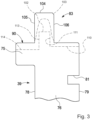
- FIG. 3 illustrating in more detail the contour of the coupon 83 with an understanding that coupon 63 has a rather similar contour.
- Second end section 75 includes a surface 90 and the coupon 83.
- the surface 90, the coupon 83 and a discourager seal mounting section 81 among others constitute the main dimensions of the second rail member 39.
- coupon 83 includes an end 104 joined by first and second opposing sides 105 and 106 forming a substantially rectangular cross-sectional area defined by 104, 104 and 106.
- This cross-sectional area complies with the nominal dimensions of a new diaphragm 30 according to the manufacturer's specification.
- a hatched line 103 illustrates an exemplary contour of a worn diaphragm 30.
- the worn part(s) of the diaphragm 30 Before cladding the worn part(s) of the diaphragm 30 the worn part(s) have to be removed in part such that the claimed welding process start on a clean machined surface of the diaphragm 30.
- the at least on machined surface can be manufactured for example by milling or the like.
- machined surfaces 110, 111, 112, 113 and 114 there are five (5) machined surfaces 110, 111, 112, 113 and 114.
- the contour of the machined surfaces 110 to 114 is smaller than the contour of a new diaphragm.
- the volume between the machined surfaces 110 to 114 and nominal dimensions (c. f. 90, 104, 105 and 106) are filled by a filler material.
- welding this filler material to the machined surfaces 110 to 114 creates a compact cladding comprising one or more layers which fills the a. m. volume.
- the cladding has to overtop the contour of a new diaphragm 30 since welding is a process that does not produce geometrically exact surfaces. This means that a part of the cladding has to be machined after the cladding process to bring the cladding in conformity with the nominal dimensions following the surface 90, the sides 105 and 106 as well as the end 104 of a new diaphragm 30.
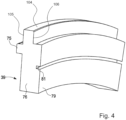
- FIG. 4 illustrates a perspective view of the second rail member 39.
- FIG. 5 illustrates a perspective view of the contour 103 of the second rail member 39 that is worn over an angle alpha in a tangential direction.
- the angle alpha illustrates the length of the worn part of a diaphragm rail member 39.
- the angle alpha illustrates the length of the worn part of a diaphragm rail member 39.
- only the worn parts of the diaphragm have to be repaired. It is in most cases not necessary to machine the diaphragm rail member 39 over its entire length. This reduces the machining time and further reduces the time and expenses for welding a cladding on the machined surfaces.
- FIGS. 6a, 6b and 6c illustrate the cross-sectional area of a worn diaphragm that has been machined according to figure 3 .
- the machined surfaces 110 to 114 make a more or less symmetric cross-sectional area.
- the weld passes are alternatingly welded on both sides of the axis of symmetry.
- a first weld pass 1 is welded on the machined surface 112, which is the end of the machined contour.
- a second weld pass 2 is welded in the corner between the machined surfaces 114 and 113.
- a third weld pass 3 is welded in the corner between the machined surfaces 110 and 111.
- the sequence of the weld passes 1 to 22 can be seen from figures 6a to 6c . Each weld pass has a number and this number describes the sequence of the welding passes welded to the diaphragm.
- FIGS 6A, 6B and 6C illustrate the process of cladding a machined surface of a diaphragm rail member.
- a weld robot or a weld automat is used.
- the welding method is MIG/MAG.
- a TIG process may also be used for the repair process however different parameters are used in this case.
- Cladding is achieved by welding several passes side by side. If necessary several layers of passes are welded to achieve the desired contour of the cladding. Up to ten layers have been welded in several applications.
- Fig 6B (2-nd layer) Pass welding angle 12 45° (0 arc length correction) 13 45° (0 arc length correction) 14 67.5° 15 67.5° 16 22.5° 17 22.5° 18 90° 19 90°
- the weld passes 12 to 19 results in a compact second layer of the cladding.
- Fig 6C (3-rd layer) Pass welding angle 20 0° 21 0° 22 0°
- the weld passes 20 to 22 results in a compact second layer of the cladding.
- the entirety of welding passes 1 to 22 forms the cladding 116.
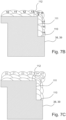
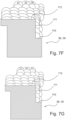
- Figures 7 to G illustrate a further embodiment of the claimed method.
- the cladding generated in this embodiment comprises ten (10) layers.
Landscapes
- Engineering & Computer Science (AREA)
- Mechanical Engineering (AREA)
- General Engineering & Computer Science (AREA)
- Physics & Mathematics (AREA)
- Plasma & Fusion (AREA)
- Arc Welding In General (AREA)
- Butt Welding And Welding Of Specific Article (AREA)
Abstract
Description
- The subject matter disclosed herein relates to the art of turbomachines and, more particularly, to a turbomachine diaphragm and a method of repairing a turbomachine diaphragm.
- In a turbomachine, air is passed into an inlet of a compressor. The air is passed through various stages of the compressor to form a compressed airflow. A portion of the compressed airflow is passed to a combustion assembly and another portion of the compressed airflow is passed to a turbine portion and used for cooling. In the combustion assembly, the compressed airflow is mixed with fuel and combusted to form a high temperature gas stream and exhaust gases. The high temperature gas stream is channeled to the turbine portion via a transition piece. The transition piece guides the high temperature gas stream toward a hot gas path of the turbine portion. The high temperature gas stream expands through various stages of the turbine portion converting thermal energy to mechanical energy that rotates a turbine shaft. The turbine portion may be used in a variety of applications including providing power to a pump, an electrical generator, a vehicle, or the like.
- From
US 9 303 512 B2 - In
US 2010/0290902 A1 a technique for refurbishing nozzle diaphragm sections of a gas turbine is described. This technique replaces an eroded or worn section of the nozzle diaphragm with a replacement part designed to be positively locked in a slot machined in the nozzle diaphragm. The replacement part is formed of a material having a similar coefficient of expansion as the material used for manufacturing the original nozzle diaphragm. The combination of the nozzle diaphragm and the replacement part conform to the original manufacturer's dimensional specifications for the nozzle diaphragm. - It is an object of the invention to further improve and enhance the possibilities of repairing a turbomachine diaphragm. Further it is an object of the invention that the repaired diaphragm has improved abilities and extended service life compared to a new diaphragm.
- These objects are achieved using a method of repairing a turbomachine diaphragm according to
claim 1. - The claimed method is rather efficient since it comprises only three steps. The first and second step consist of machining the worn or eroded coupon of the diaphragm rail such that a clean, not corroded and geometrically exact machined surface is generated. Of course, the machined surface has reduced dimensions compared to the nominal dimensions of the diaphragm rail member. The difference in size between the machined surface and the nominal dimensions of a new diaphragm are filled by a filler material, which forms the claimed cladding (third step).
- The claimed method has been successfully executed repairing diaphragm cast of a nickel iron alloy, so-called Ni-resist, and a cladding consisting of a filler material from austenitic stainless steel, such as LS 309LSI, 300 series fillers and 312. The claimed method is flexible since only the worn parts of the diaphragm rail member are machined and cladded. Those parts of the rail member that are not worn or eroded, need not be cladded. This means that solely the worn parts of the diaphragm are repaired, reducing costs for machining and cladding of the diaphragm.
- In case the distance between the machined surfaces and the nominal dimensions of the diaphragm are greater than the thickness of one layer of the cladding, several layers up to ten or even more layers can be welded to the machined surface of the diaphragm such that the whole affected feature or coupon is being restored. At the end of the welding process the surface of the cladding overtops the nominal dimensions of a new diaphragm. The last step of the claimed method consists of machining the cladding to the nominal dimensions of a new diaphragm according to the manufacturer's specification. Machining may be a milling process or any other suitable process.
- In a further advantageous embodiment each welding layer includes several weld passes welded in close proximity to each other such that a compact cladding is achieved.
- The claimed method may be further improved if the main welding parameters, such as weld speed, current and voltage, wire speed, and other parameters, well-known to the man skilled in the art, are adapted accordingly. It is possible to adapt these parameters for each pass of a layer, each layer or only once for welding a complete cladding.
- To avoid or at least reduce mechanical stress due to the welding process it is preferred that in case the machined surfaces have a symmetric cross-sectional area the passes are welded alternating on each side of the axis of symmetry.
- It has been proven advantageous if the welding process is a MIG/MAG-process. Further, it has been proven advantageous if the welding process is supported by an inert gas, wherein the inert gas preferably consists of more than 90% argon and the rest CO2. A TIG process may also be used for the repair process however different parameters are used in this case.
- After the welding process is finished, the claimed method comprises the step of machining the cladding until it has the nominal dimensions of a new diaphragm according to the manufacturer's specification.
- The above-mentioned objects are also achieved using a turbine machined diaphragm according to one of the
claims 11 to 13. - These and other advantages and features will become more apparent from the following description taken in conjunction with the drawings.
- The subject matter, which is regarded as the invention, is particularly pointed out and distinctly claimed in the claims at the conclusion of the specification. The foregoing and other features, and advantages of the invention are apparent from the following detailed description taken in conjunction with the accompanying drawings in which:
-
FIG. 1 is a schematic view of a turbomachine including a diaphragm in accordance with an exemplary embodiment; -
FIG. 2 is a perspective view of a new diaphragm; -
FIG. 3 is a partial plan view of a diaphragm rail showing an exemplary contour of a worn diaphragm rail; -
FIG. 4 is a partial plan view of a new or repaired diaphragm rail member; -
FIG. 5 is a partial plan view of the diaphragm offig. 4 being partially worn; -
FIG. 6A to 6C show different stages of Cladding a worn diaphragm rail member in accordance with a first embodiment; -
FIG. 7A to 7G show different stages of cladding a worn diaphragm rail member in accordance with a second embodiment. - The detailed description explains embodiments of the invention, together with advantages and features, by way of example with reference to the drawings.
- Referring to
FIG. 1 , a turbomachine, in accordance with an exemplary embodiment, is indicated generally at 2.Turbomachine 2 includes aturbine portion 3 having ahousing 4 that defines, at least in part, ahot gas path 10.Turbine portion 3 includes afirst stage 12, having a plurality of first stage vanes ornozzles 14, and first stage buckets orblades 16; asecond stage 17 having a plurality of second stage vanes ornozzles 18 and second stage buckets orblades 20; and athird stage 21 having a plurality of third stage vanes ornozzles 22 and third stage buckets orblades 24. Of course it should be understood thatturbine portion 3 could also include additional stages (not shown). - Hot combustion gases flow axially along
hot gas path 10 throughnozzles blades turbine portion 3. The cooling airflow, typically from a compressor portion (not shown) is directed through various components ofturbine portion 3 to reduce localized hot spots, improve wear, and increase an overall component life. Eachnozzle hot gas path 10 into the wheelspace.Diaphragm 30 cooperates with additional structure, (not shown), to limit ingestion of hot gases into the wheelspace. Loss of hot gases fromhot gas path 10 into the wheelspace reduces operational efficiency ofturbine portion 3. Over time, portions ofdiaphragm 30 may become worn and require localized repair as will be discussed more fully below. - Reference will now follow to
FIG. 2 in describing a new, not worndiaphragm 30.Diaphragm 30 is often cast from nickel-iron alloy and includes abody 34 having a sealingsection 36, afirst rail member 38 and asecond rail member 39. Sealingsection 36 includes afirst end portion 44 that extends to asecond end portion 45 through anintermediate portion 46 that defines anouter surface portion 48 and aninner surface portion 49.Outer surface portion 48 is provided with a plurality ofseal elements 50 that cooperate with additional structure (not shown) arranged in the wheel space ofturbine portion 3.First rail member 38 extends fromfirst end portion 44 andsecond rail member 39 extends fromsecond end portion 45.First rail member 38 includes afirst end section 54 that extends to asecond end section 55 through anintermediate section 56 that defines aninner surface section 58 and anouter surface section 59.Outer surface section 59 includes a discouragerseal mounting section 51 that supports a discourager seal (not separately labeled).Second end section 55 supports acoupon 63 being an integral part of thefirst rail member 38. - Similarly,
second rail member 39 includes afirst end section 74 that extends to asecond end section 75 through anintermediate section 76 that defines aninner surface section 78 and anouter surface section 79.Outer surface section 79 includes a discouragerseal mounting section 81 that supports a discourager seal (not separately labeled).Second end section 75 supports acoupon 83 being an integral part of thesecond rail member 39. Over time theoriginal coupons Worn coupons hot gas path 10 into the wheel space or other regions of the turbomachine. The loss of gases from thehot gas path 10 reduces turbine efficiency. Accordingly,diaphragms 30 are either repaired or replaced during a maintenance interval. In accordance with the exemplary embodiment, instead of a labor intensive repair of the original coupon, the exemplary embodiment discloses various techniques for replacing the original coupon with a repair coupon. - Reference will now be made to
FIG. 3 illustrating in more detail the contour of thecoupon 83 with an understanding thatcoupon 63 has a rather similar contour. -
Second end section 75 includes asurface 90 and thecoupon 83. Thesurface 90, thecoupon 83 and a discouragerseal mounting section 81 among others constitute the main dimensions of thesecond rail member 39. - More specifically,
coupon 83 includes anend 104 joined by first and second opposingsides new diaphragm 30 according to the manufacturer's specification. - A hatched
line 103 illustrates an exemplary contour of aworn diaphragm 30. By comparing the cross-sectional area and thecross-sectional area 103 of aworn diaphragm 30, it becomes apparent that due to the reducedcontour 103 of aworn diaphragm 30 the loss of hot gases increases significantly and repair of thediaphragm 30 is required. - Before cladding the worn part(s) of the
diaphragm 30 the worn part(s) have to be removed in part such that the claimed welding process start on a clean machined surface of thediaphragm 30. The at least on machined surface can be manufactured for example by milling or the like. - In the embodiment illustrated in
figure 3 there are five (5) machinedsurfaces surfaces 110 to 114 and the cross-sectional area of anew diaphragm 30 according to manufacturer's specification (c. f. thereference numerals surfaces 110 to 114 is smaller than the contour of a new diaphragm. The volume between themachined surfaces 110 to 114 and nominal dimensions (c. f. 90, 104, 105 and 106) are filled by a filler material. - Welding this filler material to the machined
surfaces 110 to 114 creates a compact cladding comprising one or more layers which fills the a. m. volume. Of course, the cladding has to overtop the contour of anew diaphragm 30 since welding is a process that does not produce geometrically exact surfaces. This means that a part of the cladding has to be machined after the cladding process to bring the cladding in conformity with the nominal dimensions following thesurface 90, thesides end 104 of anew diaphragm 30. -
FIG. 4 , wherein like reference numbers represent corresponding parts in the respective views, illustrates a perspective view of thesecond rail member 39. -
FIG. 5 , wherein like reference numbers represent corresponding parts in the respective views, illustrates a perspective view of thecontour 103 of thesecond rail member 39 that is worn over an angle alpha in a tangential direction. - The angle alpha illustrates the length of the worn part of a
diaphragm rail member 39. Of course, only the worn parts of the diaphragm have to be repaired. It is in most cases not necessary to machine thediaphragm rail member 39 over its entire length. This reduces the machining time and further reduces the time and expenses for welding a cladding on the machined surfaces. - Of course, if necessary it is possible to machine the diaphragm over the entire length of its
rail members rail member diaphragm 30. - The
figures 6a, 6b and6c illustrate the cross-sectional area of a worn diaphragm that has been machined according tofigure 3 . As can be seen fromfigure 6a themachined surfaces 110 to 114 make a more or less symmetric cross-sectional area. To reduce the thermal tensions to the diaphragm it is preferred if the weld passes are alternatingly welded on both sides of the axis of symmetry. - In this particular case, a
first weld pass 1 is welded on themachined surface 112, which is the end of the machined contour. Asecond weld pass 2 is welded in the corner between themachined surfaces third weld pass 3 is welded in the corner between themachined surfaces figures 6a to 6c . Each weld pass has a number and this number describes the sequence of the welding passes welded to the diaphragm. - The most important welding parameters have been listed in the subsequent tables that are linked to each of the figures.
- Very good results have been achieved using these welding parameters if the diaphragm is cast of nickel iron and the filler-material for welding the passes is an austenitic stainless steel. Appropriate stainless steel alloys are known under the tradenames 300 series and 312.
-
Figures 6A, 6B and6C illustrate the process of cladding a machined surface of a diaphragm rail member. In this case a weld robot or a weld automat is used. The welding method is MIG/MAG. A TIG process may also be used for the repair process however different parameters are used in this case. - Cladding is achieved by welding several passes side by side. If necessary several layers of passes are welded to achieve the desired contour of the cladding. Up to ten layers have been welded in several applications.
- In the
figures 6 and7 the passes have been numbered and in the respective tables listed below the most important welding parameters (welding speed and welding angle) have been noted.
Fig 6A (1-st layer)Pass welding angle 1 0° 2 45° (0 arc length correction) 3 45° (0 arc length correction) 4 67.5° 5 67.5° 6 22.5° 7 22.5° 8 90° 9 90° 10 22.5° 11 22.5°
Fig 6B (2-nd layer)Pass welding angle 12 45° (0 arc length correction) 13 45° (0 arc length correction) 14 67.5° 15 67.5° 16 22.5° 17 22.5° 18 90° 19 90°
Fig 6C (3-rd layer)Pass welding angle 20 0° 21 0° 22 0° cladding 116.
Figures 7 to G illustrate a further embodiment of the claimed method. The cladding generated in this embodiment comprises ten (10) layers.
Fig 7A (1-st layer)Pass welding angle 1 0° 2 0° 3 0° 4 0° 5 45° (0 arc length correction) 6 45° 7 45° 8 45° Fig 7B (2-nd layer)Pass welding angle 9 45° (repeating No 8) 10 0° 11 0° 12 0° (same as 1-4, offset +z 2-3mm) 13 0° 14 0° 15 90° 16 90° 17 90° 18 0° (repeating No 14) Fig 7C (3-rd layer)Pass welding angle 19 45° (extra buildup-platform) 20 0° 21 0° 22 0° 23 0° (same setting on X axis as 1-4; offset +Z 4-6mm) 24 0° 25 0° Fig 7D (4-th layer)Pass welding angle 26 0° 27 0° 28 0° 29 0° 30 0° 31 0° Fig 7E (5-th layer)Pass welding angle 32 0° 33 0° 34 0° 35 0° 36 0° 37 0° Fig 7F (6-th layer)Pass welding angle 38 0° 39 0° 40 0° Fig 7G (7-th layer)Pass welding angle 41 0° 42 0° 43 0° Fig 7H (8-th to 10-th layer)Pass welding angle 44 0° 45 0° 46 0° Pass welding angle 47 0° 48 0° 49 0° Pass welding angle 50 0° 51 0° - The entirety of weld passes 1 to 51 forms the
cladding 116. - While the invention has been described in detail in connection with only a limited number of embodiments, it should be readily understood that the invention is not limited to such disclosed embodiments. Rather, the invention can be modified to incorporate any number of variations, alterations, substitutions or equivalent arrangements not heretofore described, but which are commensurate with the spirit and scope of the invention. Additionally, while various embodiments of the invention have been described, it is to be understood that aspects of the invention may include only some of the described embodiments. Accordingly, the invention is not to be seen as limited by the foregoing description, but is only limited by the scope of the appended claims.
- Further aspects of the invention are provided by the subject matter of the following clauses:
-
Clause 1. A method of repairing a turbomachine diaphragm (30) consisting of cast nickel-iron (Ni-resist), the method comprising:- removing a worn coupon (63, 83) from a diaphragm rail member (38, 39).
- forming at least one machined surface (110, 111, 112, 113, 114); and
- welding a cladding (116) on the at least one machined surface (110, 111, 112, 113, 114) using a weld robot or a welding machine, wherein the cladding (116) consists of a stainless austenitic steel, and wherein welding a cladding (116) on the at least one machined surface (110, 111, 112, 113, 114) includes covering the at least one machined surface (110, 111, 112, 113, 114) with at least one welding layer such that surface of the cladding (116) overtops the nominal dimensions (104, 105, 106) of a new diaphragm (30).
-
Clause 2. The method ofclaim 1, wherein covering the at least one machined surface (110, 111, 112, 113, 114) with at least one welding layer includes welding several passes (1, 2, ..., 51) in close proximity to each other. -
Clause 3. The method ofclause 2, wherein for each pass (1, 2, ..., 51) the main weld parameters (current and voltage, wire feed speed) are adapted accordingly. -
Clause 4. The method ofclause -
Clause 5. The method ofclause 2 to 4, wherein in case the machined surfaces (110, 111, 112, 113, 114) have a symmetric cross-sectional area the passes (1, 2, .., 22) are welded alternating on each side of an axis of symmetry. -
Clause 6. The method of any one of the foregoing clauses, wherein the cladding (116) comprises more than one layer, preferably two or three layers. -
Clause 7. The method of any one of the foregoing clauses, wherein welding process is a MIG/MAG or a TIG welding process. - Clause 8. The method of any one of the foregoing clauses, wherein welding process is supported by an inert gas, wherein the inert gas consists of more than 90 % argon (Ar) and 2,5% CO2.
- Clause 9. The method of any one of the foregoing clauses, comprising the step of machining the cladding (116) to the nominal dimensions (104, 105, 106) of a new diaphragm (30).
-
Clause 10. A turbomachine diaphragm (30) comprising:- a sealing section (36) having a first end portion (44) that extends to a second end portion (45) through an intermediate portion (46);
- at least one rail member (38, 39) including a first end section (54) that extends from the first end portion (44) of the sealing section (36) to a second end section (55) through an intermediate section (56) having an inner surface section (58) and an outer surface section (59), the second end section (55) including a cladding (116) welded to the diaphragm (30), wherein the cladding (116).
-
Clause 11. The turbomachine diaphragm according toclause 10, wherein the diaphragm (30) consists of cast nickel-iron (Ni-resist). -
Clause 12. The turbomachine diaphragm according toclause -
Clause 13. The turbomachine diaphragm according toclause
Claims (12)
- A method of repairing a turbomachine diaphragm (30) consisting of cast nickel-iron (Ni-resist), the method comprising:removing a worn coupon (63, 83) from a diaphragm rail member (38, 39).forming at least one machined surface (110, 111, 112, 113, 114); andwelding a cladding (116) on the at least one machined surface (110, 111, 112, 113, 114) using a weld robot or a welding machine, wherein the cladding (116) consists of a stainless austenitic steel, and wherein welding a cladding (116) on the at least one machined surface (110, 111, 112, 113, 114) includes covering the at least one machined surface (110, 111, 112, 113, 114) with at least one welding layer such that surface of the cladding (116) overtops the nominal dimensions (104, 105, 106) of a new diaphragm (30), wherein covering the at least one machined surface (110, 111, 112, 113, 114) with at least one welding layer includes welding several passes (1, 2, ..., 51) side by side.
- The method of claim 1, wherein for each pass (1, 2, ..., 51) the main weld parameters (current and voltage, wire feed speed) are adapted accordingly.
- The method of claim 1 or 2, wherein for each pass (1, 2, ..., 51) an angle between the welding nozzle and the machined surfaces (110, 111, 112, 113, 114) are adapted.
- The method of any one of the foregoing claims, wherein the cladding (116) comprises more than one layer, preferably two or three layers.
- The method of any one of the foregoing claims, wherein the cladding (116) comprises up ten layers.
- The method of any one of the foregoing claims, wherein welding process is a MIG/MAG or a TIG welding process.
- The method of any one of the foregoing claims, wherein welding process is supported by an inert gas, wherein the inert gas consists of more than 90 % argon (Ar) and 2,5% CO2.
- The method of any one of the foregoing claims, comprising the step of machining the cladding (116) to the nominal dimensions (104, 105, 106) of a new diaphragm (30).
- A turbomachine diaphragm (30) comprising:a sealing section (36) having a first end portion (44) that extends to a second end portion (45) through an intermediate portion (46);at least one rail member (38, 39) including a first end section (54) that extends from the first end portion (44) of the sealing section (36) to a second end section (55) through an intermediate section (56) having an inner surface section (58) and an outer surface section (59), the second end section (55) including a cladding (116) welded to the diaphragm (30), wherein the cladding (116) is welded according to the method of claim 1.
- The turbomachine diaphragm according to claim 9, wherein the diaphragm (30) consists of cast nickel-iron (Ni-resist).
- The turbomachine diaphragm according to claim 9 or 10, wherein the cladding (116) consists of a stainless austenitic steel, preferably 309 LSi or 312.
- The turbomachine diaphragm according to claims 9, 10 or 11, wherein the cladding (116) includes a discourager seal (81).
Priority Applications (1)
| Application Number | Priority Date | Filing Date | Title |
|---|---|---|---|
| EP24185657.4A EP4480618A1 (en) | 2018-01-30 | 2018-01-30 | Repair of gas turbine diaphragm |
Applications Claiming Priority (2)
| Application Number | Priority Date | Filing Date | Title |
|---|---|---|---|
| EP24185657.4A EP4480618A1 (en) | 2018-01-30 | 2018-01-30 | Repair of gas turbine diaphragm |
| EP18461510.2A EP3517237B1 (en) | 2018-01-30 | 2018-01-30 | Repair of gas turbine diaphragm |
Related Parent Applications (2)
| Application Number | Title | Priority Date | Filing Date |
|---|---|---|---|
| EP18461510.2A Division-Into EP3517237B1 (en) | 2018-01-30 | 2018-01-30 | Repair of gas turbine diaphragm |
| EP18461510.2A Division EP3517237B1 (en) | 2018-01-30 | 2018-01-30 | Repair of gas turbine diaphragm |
Publications (1)
| Publication Number | Publication Date |
|---|---|
| EP4480618A1 true EP4480618A1 (en) | 2024-12-25 |
Family
ID=61132361
Family Applications (2)
| Application Number | Title | Priority Date | Filing Date |
|---|---|---|---|
| EP24185657.4A Pending EP4480618A1 (en) | 2018-01-30 | 2018-01-30 | Repair of gas turbine diaphragm |
| EP18461510.2A Active EP3517237B1 (en) | 2018-01-30 | 2018-01-30 | Repair of gas turbine diaphragm |
Family Applications After (1)
| Application Number | Title | Priority Date | Filing Date |
|---|---|---|---|
| EP18461510.2A Active EP3517237B1 (en) | 2018-01-30 | 2018-01-30 | Repair of gas turbine diaphragm |
Country Status (3)
| Country | Link |
|---|---|
| US (2) | US11148235B2 (en) |
| EP (2) | EP4480618A1 (en) |
| HU (1) | HUE069162T2 (en) |
Families Citing this family (2)
| Publication number | Priority date | Publication date | Assignee | Title |
|---|---|---|---|---|
| EP4480618A1 (en) | 2018-01-30 | 2024-12-25 | General Electric Technology GmbH | Repair of gas turbine diaphragm |
| US12331656B2 (en) * | 2020-12-08 | 2025-06-17 | Ge Infrastructure Technology Llc | Methods of forming or repairing part with overhung section, and related turbomachine part |
Citations (7)
| Publication number | Priority date | Publication date | Assignee | Title |
|---|---|---|---|---|
| JPS5542129A (en) * | 1978-09-20 | 1980-03-25 | Hitachi Ltd | Nozzle vane repair method of turbine diaphragm |
| US6118098A (en) * | 1997-10-10 | 2000-09-12 | Siemens Westinghouse Power Corporation | Turbine rotor modernization and repair method |
| US20100290902A1 (en) | 2009-05-12 | 2010-11-18 | Leading Edge Turbine Technologies, Ltd. | Repair of industrial gas turbine nozzle diaphragm packing |
| US20140064954A1 (en) * | 2012-08-30 | 2014-03-06 | General Electric Company | Turbomachine diaphragm and method of repairing a turbomachine diaphragm |
| US20140217068A1 (en) * | 2011-09-27 | 2014-08-07 | Snecma | Method for welding and for hard surface deposition of metal parts made of aluminium by a mig method with pulsed current and filler wire |
| US9068459B2 (en) * | 2012-03-05 | 2015-06-30 | General Electric Company | Turbine diaphragm airfoil, diaphragm assembly, and method of repair |
| US9303512B2 (en) | 2012-03-22 | 2016-04-05 | Hitachi Automotive Systems, Ltd. | Vane pump |
Family Cites Families (20)
| Publication number | Priority date | Publication date | Assignee | Title |
|---|---|---|---|---|
| US4782206A (en) * | 1987-01-27 | 1988-11-01 | The Babcock & Wilcox Company | Method and apparatus for controlling weld bead shape to eliminate microfissure defects when shape melting austenitic materials |
| US4940390A (en) * | 1988-05-05 | 1990-07-10 | Westinghouse Electric Corp. | Turbine system having more failure resistant rotors and repair welding of low alloy ferrous turbine components by controlled weld build-up |
| US4924581A (en) * | 1988-11-22 | 1990-05-15 | Techniair, Inc. | Turbine air seal repair process |
| US5024582A (en) * | 1990-08-14 | 1991-06-18 | Westinghouse Electric Corp. | Steam turbine rotor having graded weldments |
| ATE169850T1 (en) * | 1991-01-21 | 1998-09-15 | Sulzer Hydro Ag | METHOD FOR PRODUCING METAL WORKPIECES USING A WELDING DEVICE AND DEVICE FOR EXECUTING THE SAME |
| US5591363A (en) * | 1995-03-02 | 1997-01-07 | Westinghouse Electric Corporation | Optimized welding technique for NiMoV rotors for high temperature applications |
| US5697151A (en) * | 1995-08-07 | 1997-12-16 | General Electric Company | Method for repairing partitions of a turbine diaphragm |
| US5914055A (en) * | 1996-11-18 | 1999-06-22 | Tennessee Valley Authority | Rotor repair system and technique |
| US5794338A (en) * | 1997-04-04 | 1998-08-18 | General Electric Company | Method for repairing a turbine engine member damaged tip |
| US6568077B1 (en) * | 2000-05-11 | 2003-05-27 | General Electric Company | Blisk weld repair |
| JP2005095905A (en) | 2003-09-22 | 2005-04-14 | Toshiba Corp | Overlay diffusion repair device and method |
| SG134185A1 (en) * | 2006-01-16 | 2007-08-29 | United Technologies Corp | Turbine platform repair using laser clad |
| JP5785376B2 (en) * | 2010-10-19 | 2015-09-30 | 株式会社東芝 | Overlay welding method |
| CN102935545A (en) | 2012-11-14 | 2013-02-20 | 哈尔滨汽轮机厂有限责任公司 | Narrow-gap metal active gas (MAG) welding method for large-thickness shroud type diaphragms of turbines |
| US10016853B2 (en) * | 2013-03-14 | 2018-07-10 | Ansaldo Energia Switzerland AG | Deep trailing edge repair |
| DE102014206143A1 (en) * | 2014-04-01 | 2015-10-15 | Fraunhofer-Gesellschaft zur Förderung der angewandten Forschung e.V. | Laser deposition welding of high-temperature superalloys by means of oscillating beam guidance |
| DE102014106529B4 (en) * | 2014-05-09 | 2016-02-04 | Senvion Gmbh | Repair procedure for vortex generator and a kit for it |
| US20160045982A1 (en) * | 2014-08-18 | 2016-02-18 | Siemens Energy, Inc. | Hybrid welding/printing process |
| EP4480618A1 (en) | 2018-01-30 | 2024-12-25 | General Electric Technology GmbH | Repair of gas turbine diaphragm |
| US11135677B2 (en) * | 2018-03-06 | 2021-10-05 | General Electric Company | Laser welding of component |
-
2018
- 2018-01-30 EP EP24185657.4A patent/EP4480618A1/en active Pending
- 2018-01-30 EP EP18461510.2A patent/EP3517237B1/en active Active
- 2018-01-30 HU HUE18461510A patent/HUE069162T2/en unknown
-
2019
- 2019-08-13 US US16/239,824 patent/US11148235B2/en active Active
-
2021
- 2021-09-15 US US17/475,455 patent/US11813708B2/en active Active
Patent Citations (7)
| Publication number | Priority date | Publication date | Assignee | Title |
|---|---|---|---|---|
| JPS5542129A (en) * | 1978-09-20 | 1980-03-25 | Hitachi Ltd | Nozzle vane repair method of turbine diaphragm |
| US6118098A (en) * | 1997-10-10 | 2000-09-12 | Siemens Westinghouse Power Corporation | Turbine rotor modernization and repair method |
| US20100290902A1 (en) | 2009-05-12 | 2010-11-18 | Leading Edge Turbine Technologies, Ltd. | Repair of industrial gas turbine nozzle diaphragm packing |
| US20140217068A1 (en) * | 2011-09-27 | 2014-08-07 | Snecma | Method for welding and for hard surface deposition of metal parts made of aluminium by a mig method with pulsed current and filler wire |
| US9068459B2 (en) * | 2012-03-05 | 2015-06-30 | General Electric Company | Turbine diaphragm airfoil, diaphragm assembly, and method of repair |
| US9303512B2 (en) | 2012-03-22 | 2016-04-05 | Hitachi Automotive Systems, Ltd. | Vane pump |
| US20140064954A1 (en) * | 2012-08-30 | 2014-03-06 | General Electric Company | Turbomachine diaphragm and method of repairing a turbomachine diaphragm |
Also Published As
| Publication number | Publication date |
|---|---|
| US11148235B2 (en) | 2021-10-19 |
| EP3517237B1 (en) | 2024-11-06 |
| US11813708B2 (en) | 2023-11-14 |
| HUE069162T2 (en) | 2025-02-28 |
| US20210402527A1 (en) | 2021-12-30 |
| EP3517237A1 (en) | 2019-07-31 |
| US20200016701A1 (en) | 2020-01-16 |
Similar Documents
| Publication | Publication Date | Title |
|---|---|---|
| JP4097419B2 (en) | Turbine nozzle segment and repair method thereof | |
| US8182228B2 (en) | Turbine blade having midspan shroud with recessed wear pad and methods for manufacture | |
| EP1227218B1 (en) | Method of repairing a turbine nozzle segment | |
| US8083465B2 (en) | Repaired turbine exhaust strut heat shield vanes and repair methods | |
| US20070184182A1 (en) | Method of repairing the turbine airfoil nozzle segment | |
| JP4474146B2 (en) | Assembling repair of casting nozzle | |
| US11813708B2 (en) | Repair of gas turbine diaphragm | |
| JP4588318B2 (en) | Method for replacing a portion of a turbine shroud support | |
| JP4659968B2 (en) | Turbine nozzle segment and repair method | |
| US7185433B2 (en) | Turbine nozzle segment and method of repairing same | |
| CN110712002A (en) | Method for restoring blade or guide vane platform | |
| JP5214280B2 (en) | Turbine nozzle segment and repair method thereof | |
| US9068459B2 (en) | Turbine diaphragm airfoil, diaphragm assembly, and method of repair | |
| US9303515B2 (en) | Turbomachine diaphragm and method of repairing a turbomachine diaphragm | |
| EP1564371A2 (en) | Method of repair for cast article | |
| US20140301838A1 (en) | Repair of a gas turbine component | |
| KR20210113380A (en) | Turbine rotor blade and contact surface manufacturing method | |
| US9931719B2 (en) | Method for repairing a receiving hook for guide vanes | |
| US12042875B2 (en) | Weld-brazing techniques | |
| JP2009002338A (en) | Stationary blade ring, axial flow compressor using the same, and method for repairing stationary blade ring | |
| Storch et al. | Repair welds in turbine blades | |
| JPS6221963B2 (en) |
Legal Events
| Date | Code | Title | Description |
|---|---|---|---|
| PUAI | Public reference made under article 153(3) epc to a published international application that has entered the european phase |
Free format text: ORIGINAL CODE: 0009012 |
|
| STAA | Information on the status of an ep patent application or granted ep patent |
Free format text: STATUS: THE APPLICATION HAS BEEN PUBLISHED |
|
| AC | Divisional application: reference to earlier application |
Ref document number: 3517237 Country of ref document: EP Kind code of ref document: P |
|
| AK | Designated contracting states |
Kind code of ref document: A1 Designated state(s): AL AT BE BG CH CY CZ DE DK EE ES FI FR GB GR HR HU IE IS IT LI LT LU LV MC MK MT NL NO PL PT RO RS SE SI SK SM TR |
|
| STAA | Information on the status of an ep patent application or granted ep patent |
Free format text: STATUS: REQUEST FOR EXAMINATION WAS MADE |
|
| 17P | Request for examination filed |
Effective date: 20250331 |
|
| RAP3 | Party data changed (applicant data changed or rights of an application transferred) |
Owner name: GE VERNOVA TECHNOLOGY GMBH |