EP4480595A1 - Molding device - Google Patents
Molding device Download PDFInfo
- Publication number
- EP4480595A1 EP4480595A1 EP23756225.1A EP23756225A EP4480595A1 EP 4480595 A1 EP4480595 A1 EP 4480595A1 EP 23756225 A EP23756225 A EP 23756225A EP 4480595 A1 EP4480595 A1 EP 4480595A1
- Authority
- EP
- European Patent Office
- Prior art keywords
- temperature
- die
- forming
- metal pipe
- control unit
- Prior art date
- Legal status (The legal status is an assumption and is not a legal conclusion. Google has not performed a legal analysis and makes no representation as to the accuracy of the status listed.)
- Pending
Links
Images






Classifications
-
- B—PERFORMING OPERATIONS; TRANSPORTING
- B21—MECHANICAL METAL-WORKING WITHOUT ESSENTIALLY REMOVING MATERIAL; PUNCHING METAL
- B21D—WORKING OR PROCESSING OF SHEET METAL OR METAL TUBES, RODS OR PROFILES WITHOUT ESSENTIALLY REMOVING MATERIAL; PUNCHING METAL
- B21D26/00—Shaping without cutting otherwise than using rigid devices or tools or yieldable or resilient pads, i.e. applying fluid pressure or magnetic forces
- B21D26/02—Shaping without cutting otherwise than using rigid devices or tools or yieldable or resilient pads, i.e. applying fluid pressure or magnetic forces by applying fluid pressure
- B21D26/033—Deforming tubular bodies
-
- B—PERFORMING OPERATIONS; TRANSPORTING
- B21—MECHANICAL METAL-WORKING WITHOUT ESSENTIALLY REMOVING MATERIAL; PUNCHING METAL
- B21D—WORKING OR PROCESSING OF SHEET METAL OR METAL TUBES, RODS OR PROFILES WITHOUT ESSENTIALLY REMOVING MATERIAL; PUNCHING METAL
- B21D22/00—Shaping without cutting, by stamping, spinning, or deep-drawing
- B21D22/02—Stamping using rigid devices or tools
- B21D22/022—Stamping using rigid devices or tools by heating the blank or stamping associated with heat treatment
-
- B—PERFORMING OPERATIONS; TRANSPORTING
- B21—MECHANICAL METAL-WORKING WITHOUT ESSENTIALLY REMOVING MATERIAL; PUNCHING METAL
- B21D—WORKING OR PROCESSING OF SHEET METAL OR METAL TUBES, RODS OR PROFILES WITHOUT ESSENTIALLY REMOVING MATERIAL; PUNCHING METAL
- B21D22/00—Shaping without cutting, by stamping, spinning, or deep-drawing
- B21D22/20—Deep-drawing
- B21D22/208—Deep-drawing by heating the blank or deep-drawing associated with heat treatment
-
- B—PERFORMING OPERATIONS; TRANSPORTING
- B21—MECHANICAL METAL-WORKING WITHOUT ESSENTIALLY REMOVING MATERIAL; PUNCHING METAL
- B21D—WORKING OR PROCESSING OF SHEET METAL OR METAL TUBES, RODS OR PROFILES WITHOUT ESSENTIALLY REMOVING MATERIAL; PUNCHING METAL
- B21D24/00—Special deep-drawing arrangements in, or in connection with, presses
-
- B—PERFORMING OPERATIONS; TRANSPORTING
- B21—MECHANICAL METAL-WORKING WITHOUT ESSENTIALLY REMOVING MATERIAL; PUNCHING METAL
- B21D—WORKING OR PROCESSING OF SHEET METAL OR METAL TUBES, RODS OR PROFILES WITHOUT ESSENTIALLY REMOVING MATERIAL; PUNCHING METAL
- B21D37/00—Tools as parts of machines covered by this subclass
- B21D37/16—Heating or cooling
-
- C—CHEMISTRY; METALLURGY
- C21—METALLURGY OF IRON
- C21D—MODIFYING THE PHYSICAL STRUCTURE OF FERROUS METALS; GENERAL DEVICES FOR HEAT TREATMENT OF FERROUS OR NON-FERROUS METALS OR ALLOYS; MAKING METAL MALLEABLE, e.g. BY DECARBURISATION OR TEMPERING
- C21D1/00—General methods or devices for heat treatment, e.g. annealing, hardening, quenching or tempering
- C21D1/18—Hardening; Quenching with or without subsequent tempering
-
- C—CHEMISTRY; METALLURGY
- C21—METALLURGY OF IRON
- C21D—MODIFYING THE PHYSICAL STRUCTURE OF FERROUS METALS; GENERAL DEVICES FOR HEAT TREATMENT OF FERROUS OR NON-FERROUS METALS OR ALLOYS; MAKING METAL MALLEABLE, e.g. BY DECARBURISATION OR TEMPERING
- C21D1/00—General methods or devices for heat treatment, e.g. annealing, hardening, quenching or tempering
- C21D1/62—Quenching devices
- C21D1/673—Quenching devices for die quenching
-
- Y—GENERAL TAGGING OF NEW TECHNOLOGICAL DEVELOPMENTS; GENERAL TAGGING OF CROSS-SECTIONAL TECHNOLOGIES SPANNING OVER SEVERAL SECTIONS OF THE IPC; TECHNICAL SUBJECTS COVERED BY FORMER USPC CROSS-REFERENCE ART COLLECTIONS [XRACs] AND DIGESTS
- Y02—TECHNOLOGIES OR APPLICATIONS FOR MITIGATION OR ADAPTATION AGAINST CLIMATE CHANGE
- Y02P—CLIMATE CHANGE MITIGATION TECHNOLOGIES IN THE PRODUCTION OR PROCESSING OF GOODS
- Y02P10/00—Technologies related to metal processing
- Y02P10/25—Process efficiency
Definitions
- the present disclosure relates to a forming device.
- PTL 1 discloses a forming device including a die including a pair of a lower die and an upper die, a gas supply unit that supplies a gas into a metal pipe material held between the dies, and a heating unit that heats the metal pipe material by electrical heating.
- a forming device includes a cooling unit that causes water to flow through a flow path formed in the die in order to cool the heated metal pipe during the forming. Therefore, the forming device can perform quenching forming by bringing the cooled die into contact with the metal pipe material.
- the forming device may perform the forming such that a part of the metal material is quenched and the other parts are not quenched.
- a non-quenching area of the metal material has a high temperature when the die is opened. Therefore, when the non-quenching area is cooled to a room temperature, there is a possibility that the metal material may be warped due to thermal stress.
- an object of the present disclosure is to provide a forming device that can suppress warpage of a metal material.
- a forming device that forms a heated metal material, the forming device including a forming die that performs forming such that a quenching area of the metal material is quenched and a non-quenching area of the metal material is not quenched, and a temperature control unit that controls a temperature of the forming die such that warpage in the non-quenching area is reduced.
- the forming die performs the forming such that the quenching area of the metal material is quenched and the non-quenching area of the metal material is not quenched.
- the temperature control unit controls the temperature of the forming die such that the warpage in the non-quenching area is reduced. Therefore, when the temperature of the metal material after the forming in the non-quenching area is lowered, it is possible to reduce the warpage caused by a difference in a heat shrinkage amount at each position in the circumferential direction of the metal material.
- the temperature control unit may include a temperature measurement unit that measures a temperature of at least one of the metal material and the forming die, and control the temperature of the forming die such that a temperature difference in a circumferential direction of the metal material in the non-quenching area is reduced, based on a measurement result of the temperature measurement unit. Therefore, the temperature difference in the circumferential direction of the metal material can be identified by the temperature measurement unit. Further, the temperature control unit controls the temperature of the forming die such that the temperature difference in the circumferential direction of the metal material in the non-quenching area is reduced, based on the measurement result of the temperature measurement unit. Therefore, it is possible to more reliably suppress the occurrence of the difference in the heat shrinkage amount at each position in the circumferential direction of the metal material. Therefore, when the temperature of the metal material after the forming is lowered, it is possible to reduce the warpage caused by the difference in the heat shrinkage amount at each position in the circumferential direction.
- the temperature control unit may control the temperature of the forming die such that a material temperature in the non-quenching area when the forming die is opened after the forming is equal to or higher than a martensite start temperature. In this case, even in a case where the temperature control unit performs the temperature control of the forming die, it is possible to suppress the quenching in the non-quenching area.
- the forming die may include a first die and a second die, and the temperature control unit may control a temperature of each of the first die and the second die. Therefore, the temperature control unit can easily control the temperature of the forming die, and the temperature difference in the circumferential direction of the metal material can be easily suppressed.
- the temperature control unit may control the temperature of the forming die based on feedback information on past actual results of the forming via the forming device. In this case, the temperature control unit can appropriately control the temperature of the forming die based on the actual results of the practical forming.
- the forming device that can suppress the warpage of the metal material.
- Fig. 1 is a schematic configuration view of a forming device 1 according to the present embodiment.
- the forming device 1 is a device that forms a metal pipe having a hollow shape by blow forming.
- the forming device 1 is installed on a horizontal plane.
- the forming device 1 includes a forming die 2, a drive mechanism 3, a holding unit 4, a heating unit 5, a fluid supply unit 6, a temperature control unit 7, and a control unit 8.
- a metal pipe material 40 refers to a hollow article before the completion of forming via the forming device 1.
- the metal pipe material 40 is a steel-type pipe material that can be quenched.
- a direction in which the metal pipe material 40 extends during the forming may be referred to as a "longitudinal direction", and a direction perpendicular to the longitudinal direction may be referred to as a "width direction”.
- the forming die 2 is a die that forms a metal pipe 140 (see Figs. 5A and 5B ) from the metal pipe material 40, and includes a lower die 11 and an upper die 12 that face each other in an up-down direction.
- the lower die 11 and the upper die 12 are configured by blocks made of steel.
- Each of the lower die 11 and the upper die 12 is provided with a recessed part in which the metal pipe material 40 is accommodated.
- the respective recessed parts form a space having a target shape in which the metal pipe material is to be formed. Therefore, surfaces of the respective recessed parts are forming surfaces of the forming die 2.
- the lower die 11 is fixed to a base stage 13 via a die holder or the like.
- the upper die 12 is fixed to a slide of the drive mechanism 3 via a die holder or the like.
- the metal pipe 140 (metal pipe material 40) includes a quenching area E1 in which quenching is performed and a non-quenching area E2 in which quenching is not performed. Therefore, the forming die 2 performs the forming such that the quenching area E1 of the metal pipe material 40 is quenched and the non-quenching area E2 of the metal pipe material 40 is not quenched.
- the upper die 12 and the lower die 11 include quenching portions 12A and 11A that perform the quenching on the quenching area E1 and non-quenching portions 12B and 11B that prevents the quenching from being performed on the non-quenching area E2.
- the non-quenching area E2 is provided at a substantially central position of the metal pipe 140 (metal pipe material 40), and the quenching areas E1 are provided to interpose the non-quenching area E2 in the longitudinal direction. Therefore, the upper die 12 and the lower die 11 include the non-quenching portions 12B and 11B at the central position and the quenching portions 12A and 11A interposing the non-quenching area E2 in the longitudinal direction.
- the drive mechanism 3 is a mechanism that moves at least one of the lower die 11 and the upper die 12.
- the drive mechanism 3 has a configuration of moving only the upper die 12.
- the drive mechanism 3 includes a slide 21 that moves the upper die 12 such that the lower die 11 and the upper die 12 are joined together, a pull-back cylinder 22 as an actuator that generates a force for pulling the slide 21 upward, a main cylinder 23 as a drive source that downward-pressurizes the slide 21, and a drive source 24 that applies a driving force to the main cylinder 23.
- the holding unit 4 is a mechanism that holds the metal pipe material 40 disposed between the lower die 11 and the upper die 12.
- the holding unit 4 includes a lower electrode 26 and an upper electrode 27 that hold the metal pipe material 40 on one end side in the longitudinal direction of the forming die 2, and a lower electrode 26 and an upper electrode 27 that hold the metal pipe material 40 on the other end side in the longitudinal direction of the forming die 2.
- the lower electrodes 26 and the upper electrodes 27 on both sides in the longitudinal direction hold the metal pipe material 40 by interposing vicinities of end portions of the metal pipe material 40 from the up-down direction.
- Upper surfaces of the lower electrodes 26 and lower surfaces of the upper electrodes 27 are formed with groove portions having a shape corresponding to an outer peripheral surface of the metal pipe material 40.
- Drive mechanisms (not illustrated) are provided in the lower electrodes 26 and the upper electrodes 27 and are movable independently of each other in the up-down direction.
- the heating unit 5 heats the metal pipe material 40.
- the heating unit 5 is a mechanism that heats the metal pipe material 40 by energizing the metal pipe material 40.
- the heating unit 5 heats the metal pipe material 40 in a state where the metal pipe material 40 is spaced apart from the lower die 11 and the upper die 12, between the lower die 11 and the upper die 12.
- the heating unit 5 includes the lower electrodes 26 and the upper electrodes 27 on both sides in the longitudinal direction, and a power supply 28 that causes a current to flow through the metal pipe material 40 via the electrodes 26 and 27.
- the heating unit may be disposed in a preceding process of the forming device 1 to perform heating externally.
- the fluid supply unit 6 is a mechanism that supplies a high-pressure fluid into the metal pipe material 40 held between the lower die 11 and the upper die 12.
- the fluid supply unit 6 supplies the high-pressure fluid into the metal pipe material 40 that has been brought into a high-temperature state by being heated by the heating unit 5, to expand the metal pipe material 40.
- the fluid supply units 6 are provided on both end sides of the forming die 2 in the longitudinal direction.
- the fluid supply unit 6 includes a nozzle 31 that supplies the fluid from an opening portion of an end portion of the metal pipe material 40 to an inside of the metal pipe material 40, a drive mechanism 32 that moves the nozzle 31 forward and backward with respect to the opening portion of the metal pipe material 40, and a supply source 33 that supplies the high-pressure fluid into the metal pipe material 40 via the nozzle 31.
- the drive mechanism 32 brings the nozzle 31 into close contact with the end portion of the metal pipe material 40 in a state in which sealing performance is secured during the fluid supply and exhaust, and causes the nozzle 31 to be spaced apart from the end portion of the metal pipe material 40 in other cases.
- the fluid supply unit 6 may supply a gas such as high-pressure air and an inert gas, as the fluid. Additionally, the fluid supply unit 6 may include the heating unit 5 together with the holding unit 4 including a mechanism that moves the metal pipe material 40 in the up-down direction as the same device.
- Components of the holding unit 4, the heating unit 5, and the fluid supply unit 6 may be configured as a unitized heating and expanding unit 150.
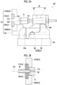
- Fig. 2A is a schematic side view illustrating the heating and expanding unit 150.
- Fig. 2B is a sectional view illustrating a state where the nozzle 31 has sealed the metal pipe material 40.
- the heating and expanding unit 150 includes the lower electrode 26, the upper electrode 27, an electrode mounting unit 151 in which the electrodes 26 and 27 are mounted, the nozzle 31, the drive mechanism 32, an elevating unit 152, and a unit base 153.
- the electrode mounting unit 151 includes an elevating frame 154 and electrode frames 156 and 157.
- the electrode frames 156 and 157 function as a part of a drive mechanism 60 that supports and moves each of the electrodes 26 and 27.
- the drive mechanism 32 drives the nozzle 31 and moves up and down together with the electrode mounting unit 151.
- the drive mechanism 32 includes a piston 61 that holds the nozzle 31, and a cylinder 62 that drives the piston.
- the elevating unit 152 includes an elevating frame base 64 attached to an upper surface of the unit base 153, and an elevating actuator 66 that applies an elevating operation to the elevating frame 154 of the electrode mounting unit 151 by using the elevating frame base 64.
- the elevating frame base 64 includes guide portions 64a and 64b that guide the elevating operation of the elevating frame 154 with respect to the unit base 153.
- the elevating unit 152 functions as a part of the drive mechanism 60 of the holding unit 4.
- the heating and expanding unit 150 includes a plurality of the unit bases 153 of which the upper surfaces have different inclination angles, and is allowed to collectively change and adjust inclination angles of the lower electrode 26, the upper electrode 27, the nozzle 31, the electrode mounting unit 151, the drive mechanism 32, and the elevating unit 152 by replacing the unit bases 153.
- the nozzle 31 is a cylindrical member into which the end portion of the metal pipe material 40 can be inserted.
- the nozzle 31 is supported by the drive mechanism 32 such that a center line of the nozzle 31 coincides with a reference line SL1.
- An inner diameter of a feed port 31a at an end portion of the nozzle 31 on the metal pipe material 40 side substantially coincides with an outer diameter of the metal pipe material 40 after expansion forming.
- the nozzle 31 supplies the high-pressure fluid from an internal flow path 63 to the metal pipe material 40.
- the high-pressure fluid include a gas.
- the control unit 8 is a device that controls the entire forming device 1.
- the control unit 8 controls the drive mechanism 3, the holding unit 4, the heating unit 5, the fluid supply unit 6, and the supply mechanism 37.
- the control unit 8 repeatedly performs the operation of forming the metal pipe material 40 using the forming die 2.
- control unit 8 controls, for example, a transport timing from a transport device, such as a robot arm, to dispose the metal pipe material 40 between the lower die 11 and the upper die 12 in an open state. Alternatively, a worker may manually dispose the metal pipe material 40 between the lower die 11 and the upper die 12. Additionally, the control unit 8 controls an actuator of the holding unit 4 and the like such that the metal pipe material 40 is supported by the lower electrodes 26 on both sides in the longitudinal direction, and then the upper electrodes 27 are lowered to interpose the metal pipe material 40. In addition, the control unit 8 controls the heating unit 5 to electrically heat the metal pipe material 40. Therefore, an axial current flows through the metal pipe material 40, and an electric resistance of the metal pipe material 40 itself causes the metal pipe material 40 itself to generate heat due to Joule heat.
- a transport timing from a transport device, such as a robot arm
- the control unit 8 controls the drive mechanism 3 to lower the upper die 12 and bring the upper die 12 close to the lower die 11, thereby closing the forming die 2. Meanwhile, the control unit 8 controls the fluid supply unit 6 to seal the opening portions of both ends of the metal pipe material 40 with the nozzle 31 and supply the fluid. Therefore, the metal pipe material 40 softened by the heating expands and comes into contact with the forming surface of the forming die 2. Then, the metal pipe material 40 is formed to follow a shape of the forming surface of the forming die 2.
- a part of the metal pipe material 40 is made to enter a gap between the lower die 11 and the upper die 12, and then die closing is further performed to crush the entering part to form a flange portion.
- the quenching area E1 of the metal pipe material 40 comes into contact with the forming surface, the metal pipe material 40 is quenched by being rapidly cooled by using the forming die 2 cooled by the temperature control unit 7.
- the temperature control unit 7 includes temperature control mechanisms 70 and 80 that control the temperature of the forming die 2.
- the temperature control mechanism 70 is provided inside the upper die 12, and controls the temperature of the forming surface of the die 12.
- the temperature control mechanism 80 is provided inside the lower die 11, and controls the temperature of the forming surface of the die 11.
- the temperature control mechanism 70 includes flow paths 71 provided in the quenching portions 12A on both sides of the die 12.
- the flow path 71 cools the forming surface of the quenching portion 12A by causing a cooling water from the supply mechanism 37 to flow therethrough.
- the temperature control mechanism 80 includes flow paths 81 provided in the quenching portions 11A on both sides of the die 11.
- the flow path 81 cools the forming surface of the quenching portion 11A by causing a cooling water from the supply mechanism 37 to flow therethrough.
- the non-quenching portions 12B and 11B include heating die blocks 12Ba and 11Ba on the forming surface side, and normal die blocks 12Bb and 11Bb on the opposite side.
- the normal die blocks 12Bb and 11Bb are blocks that connect the quenching portions 12A and 11A on both sides to each other.
- the temperature control mechanisms 70 and 80 include flow paths 72 and 82 provided in the normal die blocks 12Bb and 11Bb. The same cooling water as that in the flow paths 71 and 81 of the quenching portions 12A and 11A is supplied to the flow paths 72 and 82.
- the heating die blocks 12Ba and 11Ba are blocks having a higher temperature than the quenching portions 12A and 11A.
- a heat insulating member 75 (or a void) is provided between the quenching portions 12A and 11A and the heating die blocks 12Ba and 11Ba.
- the temperature control mechanisms 70 and 80 include flow paths 73 and 83 provided inside the heating die blocks 12Ba and 11Ba.
- the flow paths 73 and 83 cause the fluid having a higher temperature than the fluid in the flow paths 71 and 81 to flow therethrough, so that the forming surfaces of the non-quenching portions 12B and 11B have a higher temperature than the forming surfaces of the quenching portions 12A and 11A.
- the temperature control mechanisms 70 and 80 may include a heater and the like instead of the flow paths 73 and 83.
- the metal pipe 140 after the forming includes a tubular pipe portion 141, and flange portions 142 and 143.
- the pipe portion 141 includes an upper wall portion 141a provided on the upper side, a lower wall portion 141b provided on the lower side, and side wall portions 141c and 141d provided with the flange portions 142 and 143. Since the upper wall portion 141a and the lower wall portion 141b are spaced apart from each other in the up-down direction, a temperature difference is likely to be formed. In contrast, temperature measurement units 91 and 92 that measure the temperature of the metal pipe 140 are provided in the non-quenching portions 12B and 11B of the dies 12 and 11.
- the temperature measurement unit 91 is provided to be exposed from the forming surface for forming the upper wall portion 141a and to be in contact with the upper wall portion 141a. Therefore, the temperature measurement unit 91 measures the temperature of the upper wall portion 141a.
- the temperature measurement unit 92 is provided to be exposed from the forming surface for forming the lower wall portion 141b and to be in contact with the lower wall portion 141b. Therefore, the temperature measurement unit 92 measures the temperature of the lower wall portion 141b.
- the temperature measurement units 91 and 92 are not particularly limited, and for example, an optical fiber radiation thermometer may be adopted.
- temperature measurement units 93 and 94 that measure the temperatures of the non-quenching portions 12B and 11B of the dies 12 and 11 are provided in the non-quenching portions 12B and 11B of the dies 12 and 11.
- the measurement results measured by the temperature measurement units 91, 92, 93, and 94 are transmitted to the control unit 8 (see Fig. 1 ).
- the temperature control content via the temperature control unit 7 will be described.
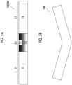
- the warpage of the metal pipe 140 will be described with reference to Figs. 5A and 5B .
- the quenching area E1 is cooled to a low temperature T3.
- the temperature T3 need only be a temperature equal to or lower than a martensitic transformation end temperature Mf. Therefore, in order to perform the quenching on the quenching area E1, the temperature control unit 7 need only control the temperature such that the temperature T3 ⁇ Mf (200°C to 250°C).
- the non-quenching area E2 has the temperatures T1 and T2 higher than the temperature T3 such that quenching is not performed.
- the temperature T1 is an upper temperature of the metal pipe 140
- the temperature T2 is a lower temperature of the metal pipe 140.
- the temperature control unit 7 controls a material temperature in the non-quenching area E2 when the forming die 2 is opened after the forming to be equal to or higher than a martensite start temperature Ms. Specifically, the temperature control unit 7 need only control the temperature such that the temperature T1 and T2 ⁇ Ms (400°C to 430°C) when the forming die 2 is opened.
- the temperatures T1 and T2 of the non-quenching area E2 are higher than a room temperature, and thus the non-quenching area E2 is cooled to the room temperature.
- the heat shrinkage amount until the metal pipe 140 is cooled to room temperature is larger on the upper side.
- the temperature difference between the upper side and the lower side is large, and the difference in the shrinkage amount is generated between the upper side and the lower side, so that the metal pipe 140 is warped as illustrated in Fig. 5B .
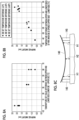
- the warpage of the metal pipe 140 will be described with reference to Fig. 8C .
- Both ends of the metal pipe 140 are fixed by a support portion 145.
- a height H1 of both end portions of the metal pipe 140 and a height H2 of the center are measured.
- a state where a difference is formed between the height H1 of both end portions and the height H2 of the central portion is a state where "warpage" has occurred.
- the difference between the height H1 of both end portions and the height H2 of the central portion is defined as a "warpage amount" as illustrated in Figs. 8A and 8B .
- the temperature control unit 7 controls the temperature of the forming die 2 such that the temperature difference in the circumferential direction of the metal pipe material 40 in the non-quenching area E2 is reduced, based on the measurement results of the temperature measurement units 91, 92, 93, and 94.
- the control unit 8 acquires the measurement results of the temperature measurement units 91, 92, 93, and 94, and controls the supply mechanism 37 such that the temperature difference in the circumferential direction in the non-quenching area E2 of the metal pipe material 40 is reduced (such that the warpage does not occur), and such that the upper temperature T1 and the lower temperature T2 have desired values.
- the temperature control unit 7 may control the temperature of the forming die 2, based on feedback information on the past actual results of the forming via the forming device 1. For example, the forming device 1 acquires a relationship between the temperature difference in the forming die 2 (and the metal pipe 140) and the magnitude of the warpage after a predetermined number of the forming operations are performed. In this case, the control unit 8 analyzes how much warpage occurs depending on the degree of the temperature difference, to create training data. In this manner, the control unit 8 performs learning using the training data as the feedback information.
- control unit 8 estimates how much warpage occurs by referring to the measurement results of the temperature measurement units 91, 92, 93, and 94 in a case of the next forming, and controls the temperature of the forming die 2 in a case where the warpage is large.
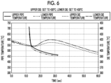
- Figs. 6 to 7B are graphs in which temporal changes in the temperature of the upper die 12 and the temperature of the lower die 11 are plotted, and temporal change in the temperatures of the upper side and the lower side of the metal pipe material 40 (metal pipe 140) corresponding thereto are plotted.
- Fig. 8A is a graph in which a relationship between the temperature difference between the upper die 12 and the lower die 11, and the warpage amount of the metal pipe 140 are plotted.
- Fig. 8B is a graph in which a relationship between the temperature difference between the upper side and the lower side of the metal pipe 140, and the warpage amount of the metal pipe 140 when the forming die 2 is opened is plotted.
- the temperature difference between the upper and lower sides of the metal pipe 140 is reduced in a case where the set temperature of the upper die 12 is set to 395°C (die set temperature difference ⁇ 35°C) as illustrated in Fig. 7A , rather than in a case where the set temperatures of the upper die 12 and the lower die 11 are set to 430°C such that there is no temperature difference (die set temperature difference ⁇ 0°C) as illustrated in Fig. 6 .
- the temperature difference between the upper and lower sides of the metal pipe 140 is reduced in a case where the set temperature of the upper die 12 is set to 395°C (die set temperature difference ⁇ 35°C) rather than in a case where the temperature of the upper die 12 is set to 370°C (die set temperature difference ⁇ 60°C) as illustrated in Fig. 7B .
- the warpage amount is reduced in a case where the die set temperature difference is ⁇ 35°C and the temperature difference between the upper and lower sides of the metal pipe 140 is reduced.
- the warpage amount is the smallest in a case where the temperature difference between the upper die 12 and the lower die 11 is 35°C.
- the temperature difference between the upper and lower sides of the pipe is the smallest by setting the die set temperature difference to ⁇ 35°C, and as a result, it can be confirmed that the warpage amount is the smallest.
- the temperature control unit 7 can reduce the warpage of the metal pipe 140 by lowering the set temperature of the upper die 12 based on 430°C as the set temperature of the forming die 2.
- Figs. 10A to 10C are results of evaluating a hardness distribution of the metal pipe 140 related to each temperature control illustrated in Figs. 6 to 9B .
- the metal pipe 140 was cut at a roughing cutting position CL and cut out, and the hardness distributions at sectional measurement positions A and B were measured.
- the sectional measurement position A is any position in the quenching area E1.
- the sectional measurement position B is any position in the non-quenching area E2.
- the micro-Vickers hardness at measurement positions P1 to P5 in each section was measured. As illustrated in Figs.
- the forming die 2 performs the forming such that the quenching area E1 of the metal material is quenched and the non-quenching area E2 of the metal material is not quenched.
- the temperature control unit 7 controls the temperature of the forming die 2 such that the warpage in the non-quenching area E2 is reduced. Therefore, when the temperature of the metal material after the forming in the non-quenching area E2 is lowered, it is possible to reduce the warpage caused by the difference in the heat shrinkage amount at each position in the circumferential direction of the metal material.
- the temperature control unit 7 includes the temperature measurement units 91, 92, 93, and 94 that measure the temperature of at least one of the metal material and the forming die 2, and controls the temperature of the forming die 2 such that the temperature difference in the circumferential direction of the metal material in the non-quenching area E2 is reduced, based on the measurement results of the temperature measurement units 91, 92, 93, and 94. Therefore, the temperature measurement units 91, 92, 93, and 94 can identify the temperature difference in the circumferential direction of the metal material.
- the temperature control unit 7 controls the temperature of the forming die 2 such that the temperature difference in the circumferential direction of the metal material in the non-quenching area E2 is reduced, based on the measurement results of the temperature measurement units 91, 92, 93, and 94. Therefore, it is possible to more reliably suppress the occurrence of the difference in the heat shrinkage amount at each position in the circumferential direction of the metal material. Therefore, when the temperature of the metal material after the forming is lowered, it is possible to reduce the warpage caused by the difference in the heat shrinkage amount at each position in the circumferential direction.
- the temperature control unit 7 may control the temperature of the forming die 2 such that a material temperature in the non-quenching area E2 when the forming die 2 is opened after the forming is equal to or higher than the martensite start temperature. In this case, even in a case where the temperature control unit 7 performs the temperature control of the forming die 2, it is possible to suppress the quenching in the non-quenching area E2.
- the forming die 2 may include the upper die 12 (first die) and the lower die 11 (second die), and the temperature control unit 7 may control the temperature of each of the upper die 12 and the lower die 11. Therefore, the temperature control unit 7 can easily control the temperature of the forming die 2, and the temperature difference in the circumferential direction of the metal pipe material 40 can be easily suppressed.
- the temperature control unit 7 may control the temperature of the forming die 2, based on feedback information on the past actual results of the forming via the forming device 1. In this case, the temperature control unit 7 can appropriately control the temperature of the forming die 2 based on the actual results of the practical forming.
- a shape of the metal pipe after the forming is not particularly limited, and a metal pipe without a flange may be formed instead of the metal pipe with the flange.
- the forming device need only be a forming device that heats a metal material to perform the quenching, and a forming device using a hot stamping method may be adopted.
- the metal material is a plate material. It should be noted that, in a case of the plate material, since the forming surface of the die comes into contact with both a front surface and a back surface during the forming, a temperature difference in a circumferential direction of the plate material is likely to be suppressed. On the other hand, in a case of the metal pipe, a portion that comes into contact with the upper die and a portion that comes into contact with the lower die are spaced apart from each other, so that the temperature difference is likely to occur. Therefore, in a case where the metal pipe is formed, the effects of the present disclosure are more remarkable.
- a forming device that forms a heated metal material, the forming device including: a forming die that performs forming such that a quenching area of the metal material is quenched and a non-quenching area of the metal material is not quenched; and a temperature control unit that controls a temperature of the forming die such that warpage in the non-quenching area is reduced.
- the temperature control unit includes a temperature measurement unit that measures a temperature of at least one of the metal material and the forming die, and controls the temperature of the forming die such that a temperature difference in a circumferential direction of the metal material in the non-quenching area is reduced, based on a measurement result of the temperature measurement unit.
- the forming device in which the temperature control unit controls the temperature of the forming die such that a material temperature in the non-quenching area when the forming die is opened after the forming is equal to or higher than a martensite start temperature.
- the forming device in which the forming die includes a first die and a second die, and the temperature control unit controls a temperature of each of the first die and the second die.
- the forming device according to any one of aspects 1 to 4, in which the temperature control unit controls the temperature of the forming die based on feedback information on past actual results of the forming via the forming device.
Landscapes
- Engineering & Computer Science (AREA)
- Mechanical Engineering (AREA)
- Physics & Mathematics (AREA)
- Chemical & Material Sciences (AREA)
- Thermal Sciences (AREA)
- Fluid Mechanics (AREA)
- Crystallography & Structural Chemistry (AREA)
- Materials Engineering (AREA)
- Metallurgy (AREA)
- Organic Chemistry (AREA)
- Shaping Metal By Deep-Drawing, Or The Like (AREA)
- Moulds For Moulding Plastics Or The Like (AREA)
- Heat Treatment Of Articles (AREA)
Abstract
Description
- The present disclosure relates to a forming device.
- In the related art, a forming device that forms a heated metal material has been known. For example,
PTL 1 discloses a forming device including a die including a pair of a lower die and an upper die, a gas supply unit that supplies a gas into a metal pipe material held between the dies, and a heating unit that heats the metal pipe material by electrical heating. Such a forming device includes a cooling unit that causes water to flow through a flow path formed in the die in order to cool the heated metal pipe during the forming. Therefore, the forming device can perform quenching forming by bringing the cooled die into contact with the metal pipe material. - [PTL 1]
Japanese Unexamined Patent Publication No. 2009-220141 - Here, the forming device may perform the forming such that a part of the metal material is quenched and the other parts are not quenched. In this case, a non-quenching area of the metal material has a high temperature when the die is opened. Therefore, when the non-quenching area is cooled to a room temperature, there is a possibility that the metal material may be warped due to thermal stress.
- Therefore, an object of the present disclosure is to provide a forming device that can suppress warpage of a metal material.
- According to an aspect of the present disclosure, there is provided a forming device that forms a heated metal material, the forming device including a forming die that performs forming such that a quenching area of the metal material is quenched and a non-quenching area of the metal material is not quenched, and a temperature control unit that controls a temperature of the forming die such that warpage in the non-quenching area is reduced.
- In the forming device, the forming die performs the forming such that the quenching area of the metal material is quenched and the non-quenching area of the metal material is not quenched. Here, the temperature control unit controls the temperature of the forming die such that the warpage in the non-quenching area is reduced. Therefore, when the temperature of the metal material after the forming in the non-quenching area is lowered, it is possible to reduce the warpage caused by a difference in a heat shrinkage amount at each position in the circumferential direction of the metal material.
- The temperature control unit may include a temperature measurement unit that measures a temperature of at least one of the metal material and the forming die, and control the temperature of the forming die such that a temperature difference in a circumferential direction of the metal material in the non-quenching area is reduced, based on a measurement result of the temperature measurement unit. Therefore, the temperature difference in the circumferential direction of the metal material can be identified by the temperature measurement unit. Further, the temperature control unit controls the temperature of the forming die such that the temperature difference in the circumferential direction of the metal material in the non-quenching area is reduced, based on the measurement result of the temperature measurement unit. Therefore, it is possible to more reliably suppress the occurrence of the difference in the heat shrinkage amount at each position in the circumferential direction of the metal material. Therefore, when the temperature of the metal material after the forming is lowered, it is possible to reduce the warpage caused by the difference in the heat shrinkage amount at each position in the circumferential direction.
- The temperature control unit may control the temperature of the forming die such that a material temperature in the non-quenching area when the forming die is opened after the forming is equal to or higher than a martensite start temperature. In this case, even in a case where the temperature control unit performs the temperature control of the forming die, it is possible to suppress the quenching in the non-quenching area.
- The forming die may include a first die and a second die, and the temperature control unit may control a temperature of each of the first die and the second die. Therefore, the temperature control unit can easily control the temperature of the forming die, and the temperature difference in the circumferential direction of the metal material can be easily suppressed.
- The temperature control unit may control the temperature of the forming die based on feedback information on past actual results of the forming via the forming device. In this case, the temperature control unit can appropriately control the temperature of the forming die based on the actual results of the practical forming.
- According to the present disclosure, it is possible to provide the forming device that can suppress the warpage of the metal material.
-
-
Fig. 1 is a schematic configuration view illustrating a forming device according to an embodiment of the present disclosure. -
Fig. 2A is a schematic side view illustrating a heating and expanding unit.Fig. 2B is a sectional view illustrating a state where a nozzle has sealed a metal pipe material. -
Fig. 3 is a schematic sectional view illustrating a temperature control mechanism of a forming die. -
Fig. 4 is a sectional view of the forming die and a metal pipe in a non-quenching area. -
Figs. 5A and 5B are schematic views illustrating a reason why warpage of the metal pipe occurs. -
Fig. 6 is a graph illustrating temperature changes in a die and the metal pipe. -
Figs. 7A and 7B are graphs illustrating temperature changes in the die and the metal pipe. -
Fig. 8A is a graph illustrating a relationship between a set temperature difference between upper and lower dies, and a warpage amount, andFig. 8B is a graph illustrating a relationship between a temperature difference between upper and lower sides of the metal pipe, and a warpage amount. -
Figs. 9A and 9B are views illustrating a method of measuring hardness. -
Figs. 10A to 10C are graphs illustrating a measurement result of the hardness. - Hereinafter, a preferred embodiment of a forming device according to the present disclosure will be described with reference to the drawings. In the drawings, the same reference numerals will be given to the same portions or equivalent portions, and the redundant description thereof will be omitted.
-
Fig. 1 is a schematic configuration view of a formingdevice 1 according to the present embodiment. As illustrated inFig. 1 , the formingdevice 1 is a device that forms a metal pipe having a hollow shape by blow forming. In the present embodiment, the formingdevice 1 is installed on a horizontal plane. The formingdevice 1 includes a forming die 2, adrive mechanism 3, aholding unit 4, aheating unit 5, afluid supply unit 6, atemperature control unit 7, and acontrol unit 8. In the present specification, a metal pipe material 40 (metal material) refers to a hollow article before the completion of forming via the formingdevice 1. Themetal pipe material 40 is a steel-type pipe material that can be quenched. In addition, in a horizontal direction, a direction in which themetal pipe material 40 extends during the forming may be referred to as a "longitudinal direction", and a direction perpendicular to the longitudinal direction may be referred to as a "width direction". - The forming die 2 is a die that forms a metal pipe 140 (see
Figs. 5A and 5B ) from themetal pipe material 40, and includes alower die 11 and anupper die 12 that face each other in an up-down direction. Thelower die 11 and theupper die 12 are configured by blocks made of steel. Each of thelower die 11 and theupper die 12 is provided with a recessed part in which themetal pipe material 40 is accommodated. In a state where thelower die 11 and theupper die 12 are in close contact with each other (die closed state), the respective recessed parts form a space having a target shape in which the metal pipe material is to be formed. Therefore, surfaces of the respective recessed parts are forming surfaces of the formingdie 2. Thelower die 11 is fixed to abase stage 13 via a die holder or the like. Theupper die 12 is fixed to a slide of thedrive mechanism 3 via a die holder or the like. - Here, in the present embodiment, the metal pipe 140 (metal pipe material 40) includes a quenching area E1 in which quenching is performed and a non-quenching area E2 in which quenching is not performed. Therefore, the forming
die 2 performs the forming such that the quenching area E1 of themetal pipe material 40 is quenched and the non-quenching area E2 of themetal pipe material 40 is not quenched. Theupper die 12 and thelower die 11 include quenchingportions non-quenching portions upper die 12 and thelower die 11 include thenon-quenching portions quenching portions - The
drive mechanism 3 is a mechanism that moves at least one of thelower die 11 and theupper die 12. InFig. 1 , thedrive mechanism 3 has a configuration of moving only theupper die 12. Thedrive mechanism 3 includes aslide 21 that moves theupper die 12 such that thelower die 11 and theupper die 12 are joined together, a pull-back cylinder 22 as an actuator that generates a force for pulling theslide 21 upward, amain cylinder 23 as a drive source that downward-pressurizes theslide 21, and adrive source 24 that applies a driving force to themain cylinder 23. - The holding
unit 4 is a mechanism that holds themetal pipe material 40 disposed between thelower die 11 and theupper die 12. The holdingunit 4 includes a lower electrode 26 and an upper electrode 27 that hold themetal pipe material 40 on one end side in the longitudinal direction of the formingdie 2, and a lower electrode 26 and an upper electrode 27 that hold themetal pipe material 40 on the other end side in the longitudinal direction of the formingdie 2. The lower electrodes 26 and the upper electrodes 27 on both sides in the longitudinal direction hold themetal pipe material 40 by interposing vicinities of end portions of themetal pipe material 40 from the up-down direction. Upper surfaces of the lower electrodes 26 and lower surfaces of the upper electrodes 27 are formed with groove portions having a shape corresponding to an outer peripheral surface of themetal pipe material 40. Drive mechanisms (not illustrated) are provided in the lower electrodes 26 and the upper electrodes 27 and are movable independently of each other in the up-down direction. - The
heating unit 5 heats themetal pipe material 40. Theheating unit 5 is a mechanism that heats themetal pipe material 40 by energizing themetal pipe material 40. Theheating unit 5 heats themetal pipe material 40 in a state where themetal pipe material 40 is spaced apart from thelower die 11 and theupper die 12, between thelower die 11 and theupper die 12. Theheating unit 5 includes the lower electrodes 26 and the upper electrodes 27 on both sides in the longitudinal direction, and apower supply 28 that causes a current to flow through themetal pipe material 40 via the electrodes 26 and 27. The heating unit may be disposed in a preceding process of the formingdevice 1 to perform heating externally. - The
fluid supply unit 6 is a mechanism that supplies a high-pressure fluid into themetal pipe material 40 held between thelower die 11 and theupper die 12. Thefluid supply unit 6 supplies the high-pressure fluid into themetal pipe material 40 that has been brought into a high-temperature state by being heated by theheating unit 5, to expand themetal pipe material 40. Thefluid supply units 6 are provided on both end sides of the formingdie 2 in the longitudinal direction. Thefluid supply unit 6 includes anozzle 31 that supplies the fluid from an opening portion of an end portion of themetal pipe material 40 to an inside of themetal pipe material 40, adrive mechanism 32 that moves thenozzle 31 forward and backward with respect to the opening portion of themetal pipe material 40, and asupply source 33 that supplies the high-pressure fluid into themetal pipe material 40 via thenozzle 31. Thedrive mechanism 32 brings thenozzle 31 into close contact with the end portion of themetal pipe material 40 in a state in which sealing performance is secured during the fluid supply and exhaust, and causes thenozzle 31 to be spaced apart from the end portion of themetal pipe material 40 in other cases. Thefluid supply unit 6 may supply a gas such as high-pressure air and an inert gas, as the fluid. Additionally, thefluid supply unit 6 may include theheating unit 5 together with the holdingunit 4 including a mechanism that moves themetal pipe material 40 in the up-down direction as the same device. - Components of the holding
unit 4, theheating unit 5, and thefluid supply unit 6 may be configured as a unitized heating and expandingunit 150.Fig. 2A is a schematic side view illustrating the heating and expandingunit 150.Fig. 2B is a sectional view illustrating a state where thenozzle 31 has sealed themetal pipe material 40. - As illustrated in
Fig. 2A , the heating and expandingunit 150 includes the lower electrode 26, the upper electrode 27, anelectrode mounting unit 151 in which the electrodes 26 and 27 are mounted, thenozzle 31, thedrive mechanism 32, an elevating unit 152, and aunit base 153. Theelectrode mounting unit 151 includes an elevatingframe 154 and electrode frames 156 and 157. The electrode frames 156 and 157 function as a part of adrive mechanism 60 that supports and moves each of the electrodes 26 and 27. Thedrive mechanism 32 drives thenozzle 31 and moves up and down together with theelectrode mounting unit 151. Thedrive mechanism 32 includes apiston 61 that holds thenozzle 31, and acylinder 62 that drives the piston. The elevating unit 152 includes an elevatingframe base 64 attached to an upper surface of theunit base 153, and an elevatingactuator 66 that applies an elevating operation to the elevatingframe 154 of theelectrode mounting unit 151 by using the elevatingframe base 64. The elevatingframe base 64 includesguide portions frame 154 with respect to theunit base 153. The elevating unit 152 functions as a part of thedrive mechanism 60 of the holdingunit 4. The heating and expandingunit 150 includes a plurality of the unit bases 153 of which the upper surfaces have different inclination angles, and is allowed to collectively change and adjust inclination angles of the lower electrode 26, the upper electrode 27, thenozzle 31, theelectrode mounting unit 151, thedrive mechanism 32, and the elevating unit 152 by replacing the unit bases 153. - The
nozzle 31 is a cylindrical member into which the end portion of themetal pipe material 40 can be inserted. Thenozzle 31 is supported by thedrive mechanism 32 such that a center line of thenozzle 31 coincides with a reference line SL1. An inner diameter of afeed port 31a at an end portion of thenozzle 31 on themetal pipe material 40 side substantially coincides with an outer diameter of themetal pipe material 40 after expansion forming. In this state, thenozzle 31 supplies the high-pressure fluid from aninternal flow path 63 to themetal pipe material 40. Examples of the high-pressure fluid include a gas. - Returning to
Fig. 1 , thetemperature control unit 7 is a mechanism that controls a temperature of the formingdie 2. Thetemperature control unit 7 controls the temperature of the formingdie 2 such that the warpage in the non-quenching area E2 is reduced. Thetemperature control unit 7 can rapidly cool themetal pipe material 40 when the expandedmetal pipe material 40 comes into contact with the forming surface of the formingdie 2, by cooling the formingdie 2 in thequenching portions temperature control unit 7 can control the temperature of themetal pipe material 40 to a temperature at which the quenching does not occur when the expandedmetal pipe material 40 comes into contact with the forming surface of the formingdie 2, by performing the temperature control of the formingdie 2 in thenon-quenching portions temperature control unit 7 includes flow paths formed inside thelower die 11 and theupper die 12, asupply mechanism 37 that supplies a temperature control medium and causes the temperature control medium to circulate through the flow paths, and acontrol unit 8 that controls thesupply mechanism 37. - The
control unit 8 is a device that controls the entire formingdevice 1. Thecontrol unit 8 controls thedrive mechanism 3, the holdingunit 4, theheating unit 5, thefluid supply unit 6, and thesupply mechanism 37. Thecontrol unit 8 repeatedly performs the operation of forming themetal pipe material 40 using the formingdie 2. - Specifically, the
control unit 8 controls, for example, a transport timing from a transport device, such as a robot arm, to dispose themetal pipe material 40 between thelower die 11 and theupper die 12 in an open state. Alternatively, a worker may manually dispose themetal pipe material 40 between thelower die 11 and theupper die 12. Additionally, thecontrol unit 8 controls an actuator of the holdingunit 4 and the like such that themetal pipe material 40 is supported by the lower electrodes 26 on both sides in the longitudinal direction, and then the upper electrodes 27 are lowered to interpose themetal pipe material 40. In addition, thecontrol unit 8 controls theheating unit 5 to electrically heat themetal pipe material 40. Therefore, an axial current flows through themetal pipe material 40, and an electric resistance of themetal pipe material 40 itself causes themetal pipe material 40 itself to generate heat due to Joule heat. - The
control unit 8 controls thedrive mechanism 3 to lower theupper die 12 and bring theupper die 12 close to thelower die 11, thereby closing the formingdie 2. Meanwhile, thecontrol unit 8 controls thefluid supply unit 6 to seal the opening portions of both ends of themetal pipe material 40 with thenozzle 31 and supply the fluid. Therefore, themetal pipe material 40 softened by the heating expands and comes into contact with the forming surface of the formingdie 2. Then, themetal pipe material 40 is formed to follow a shape of the forming surface of the formingdie 2. In addition, in a case where a metal pipe with a flange is formed, a part of themetal pipe material 40 is made to enter a gap between thelower die 11 and theupper die 12, and then die closing is further performed to crush the entering part to form a flange portion. When the quenching area E1 of themetal pipe material 40 comes into contact with the forming surface, themetal pipe material 40 is quenched by being rapidly cooled by using the formingdie 2 cooled by thetemperature control unit 7. - The
temperature control unit 7 will be described in more detail with reference toFig. 3 . Thetemperature control unit 7 includestemperature control mechanisms die 2. Thetemperature control mechanism 70 is provided inside theupper die 12, and controls the temperature of the forming surface of thedie 12. Thetemperature control mechanism 80 is provided inside thelower die 11, and controls the temperature of the forming surface of thedie 11. Thetemperature control mechanism 70 includesflow paths 71 provided in thequenching portions 12A on both sides of thedie 12. Theflow path 71 cools the forming surface of the quenchingportion 12A by causing a cooling water from thesupply mechanism 37 to flow therethrough. Thetemperature control mechanism 80 includesflow paths 81 provided in thequenching portions 11A on both sides of thedie 11. Theflow path 81 cools the forming surface of the quenchingportion 11A by causing a cooling water from thesupply mechanism 37 to flow therethrough. - Here, the
non-quenching portions quenching portions temperature control mechanisms flow paths
The same cooling water as that in theflow paths portions flow paths portions portions temperature control mechanisms flow paths flow paths flow paths non-quenching portions portions temperature control mechanisms flow paths - As illustrated in
Fig. 4 , themetal pipe 140 after the forming includes atubular pipe portion 141, andflange portions pipe portion 141 includes anupper wall portion 141a provided on the upper side, alower wall portion 141b provided on the lower side, andside wall portions flange portions upper wall portion 141a and thelower wall portion 141b are spaced apart from each other in the up-down direction, a temperature difference is likely to be formed. In contrast,temperature measurement units metal pipe 140 are provided in thenon-quenching portions temperature measurement unit 91 is provided to be exposed from the forming surface for forming theupper wall portion 141a and to be in contact with theupper wall portion 141a. Therefore, thetemperature measurement unit 91 measures the temperature of theupper wall portion 141a. Thetemperature measurement unit 92 is provided to be exposed from the forming surface for forming thelower wall portion 141b and to be in contact with thelower wall portion 141b. Therefore, thetemperature measurement unit 92 measures the temperature of thelower wall portion 141b. Thetemperature measurement units temperature measurement units non-quenching portions non-quenching portions temperature measurement units Fig. 1 ). - Hereinafter, the temperature control content via the
temperature control unit 7 will be described. First, the warpage of themetal pipe 140 will be described with reference toFigs. 5A and 5B . As illustrated inFig. 5A , immediately after the formingdie 2 is opened, the quenching area E1 is cooled to a low temperature T3. The temperature T3 need only be a temperature equal to or lower than a martensitic transformation end temperature Mf. Therefore, in order to perform the quenching on the quenching area E1, thetemperature control unit 7 need only control the temperature such that the temperature T3 ≤ Mf (200°C to 250°C). - On the other hand, the non-quenching area E2 has the temperatures T1 and T2 higher than the temperature T3 such that quenching is not performed. The temperature T1 is an upper temperature of the
metal pipe 140, and the temperature T2 is a lower temperature of themetal pipe 140. Thetemperature control unit 7 controls a material temperature in the non-quenching area E2 when the formingdie 2 is opened after the forming to be equal to or higher than a martensite start temperature Ms. Specifically, thetemperature control unit 7 need only control the temperature such that the temperature T1 and T2 ≥ Ms (400°C to 430°C) when the formingdie 2 is opened. In this way, the temperatures T1 and T2 of the non-quenching area E2 are higher than a room temperature, and thus the non-quenching area E2 is cooled to the room temperature. Here, since the upper temperature T1 is lower than the lower temperature T2, the heat shrinkage amount until themetal pipe 140 is cooled to room temperature is larger on the upper side. In this way, in the non-quenching area E2, the temperature difference between the upper side and the lower side is large, and the difference in the shrinkage amount is generated between the upper side and the lower side, so that themetal pipe 140 is warped as illustrated inFig. 5B . Here, the warpage of themetal pipe 140 will be described with reference toFig. 8C . Both ends of themetal pipe 140 are fixed by asupport portion 145. In this state, a height H1 of both end portions of themetal pipe 140 and a height H2 of the center are measured. In this case, a state where a difference is formed between the height H1 of both end portions and the height H2 of the central portion is a state where "warpage" has occurred. In addition, the difference between the height H1 of both end portions and the height H2 of the central portion is defined as a "warpage amount" as illustrated inFigs. 8A and 8B . - Therefore, the
temperature control unit 7 controls the temperature of the formingdie 2 such that the temperature difference in the circumferential direction of themetal pipe material 40 in the non-quenching area E2 is reduced, based on the measurement results of thetemperature measurement units control unit 8 acquires the measurement results of thetemperature measurement units supply mechanism 37 such that the temperature difference in the circumferential direction in the non-quenching area E2 of themetal pipe material 40 is reduced (such that the warpage does not occur), and such that the upper temperature T1 and the lower temperature T2 have desired values. - The
temperature control unit 7 may control the temperature of the formingdie 2, based on feedback information on the past actual results of the forming via the formingdevice 1. For example, the formingdevice 1 acquires a relationship between the temperature difference in the forming die 2 (and the metal pipe 140) and the magnitude of the warpage after a predetermined number of the forming operations are performed. In this case, thecontrol unit 8 analyzes how much warpage occurs depending on the degree of the temperature difference, to create training data. In this manner, thecontrol unit 8 performs learning using the training data as the feedback information. In this manner, thecontrol unit 8 estimates how much warpage occurs by referring to the measurement results of thetemperature measurement units die 2 in a case where the warpage is large. - An example of specific temperature control by the
temperature control unit 7 will be described with reference toFigs. 6 to 8C .Figs. 6 to 7B are graphs in which temporal changes in the temperature of theupper die 12 and the temperature of thelower die 11 are plotted, and temporal change in the temperatures of the upper side and the lower side of the metal pipe material 40 (metal pipe 140) corresponding thereto are plotted.Fig. 8A is a graph in which a relationship between the temperature difference between theupper die 12 and thelower die 11, and the warpage amount of themetal pipe 140 are plotted.Fig. 8B is a graph in which a relationship between the temperature difference between the upper side and the lower side of themetal pipe 140, and the warpage amount of themetal pipe 140 when the formingdie 2 is opened is plotted. - The temperature difference between the upper and lower sides of the
metal pipe 140 is reduced in a case where the set temperature of theupper die 12 is set to 395°C (die set temperature difference Δ35°C) as illustrated inFig. 7A , rather than in a case where the set temperatures of theupper die 12 and thelower die 11 are set to 430°C such that there is no temperature difference (die set temperature difference Δ0°C) as illustrated inFig. 6 . In addition, the temperature difference between the upper and lower sides of themetal pipe 140 is reduced in a case where the set temperature of theupper die 12 is set to 395°C (die set temperature difference Δ35°C) rather than in a case where the temperature of theupper die 12 is set to 370°C (die set temperature difference Δ60°C) as illustrated inFig. 7B . Even with reference toFigs. 8A and 8B , in a case where the die set temperature difference is Δ35°C and the temperature difference between the upper and lower sides of themetal pipe 140 is reduced, the warpage amount is reduced. For example, inFig. 8A , the warpage amount is the smallest in a case where the temperature difference between theupper die 12 and thelower die 11 is 35°C. In addition, inFig. 8B , the temperature difference between the upper and lower sides of the pipe is the smallest by setting the die set temperature difference to Δ35°C, and as a result, it can be confirmed that the warpage amount is the smallest. Thetemperature control unit 7 can reduce the warpage of themetal pipe 140 by lowering the set temperature of theupper die 12 based on 430°C as the set temperature of the formingdie 2. -
Figs. 10A to 10C are results of evaluating a hardness distribution of themetal pipe 140 related to each temperature control illustrated inFigs. 6 to 9B . In the evaluation, as illustrated inFig. 9A , themetal pipe 140 was cut at a roughing cutting position CL and cut out, and the hardness distributions at sectional measurement positions A and B were measured. The sectional measurement position A is any position in the quenching area E1. The sectional measurement position B is any position in the non-quenching area E2. In addition, as illustrated inFig. 9B , the micro-Vickers hardness at measurement positions P1 to P5 in each section was measured. As illustrated inFigs. 10A to 10C , it is confirmed that, at any die set temperature, the quenching is performed at the sectional measurement position A of the quenching area E1, and the hardness can be secured at each of the positions P1 to P5. In addition, it is confirmed that, at the sectional measurement position B of the non-quenching area E2, the hardness at each of the positions P1 to P5 is low, and partial quenching suppression, which is the original purpose, can be achieved, and the hardness values are not affected. - Hereinafter, the actions and effects of the forming
device 1 according to the present embodiment will be described. - In the forming
device 1, the formingdie 2 performs the forming such that the quenching area E1 of the metal material is quenched and the non-quenching area E2 of the metal material is not quenched. Here, thetemperature control unit 7 controls the temperature of the formingdie 2 such that the warpage in the non-quenching area E2 is reduced. Therefore, when the temperature of the metal material after the forming in the non-quenching area E2 is lowered, it is possible to reduce the warpage caused by the difference in the heat shrinkage amount at each position in the circumferential direction of the metal material. - In the forming
device 1, thetemperature control unit 7 includes thetemperature measurement units die 2, and controls the temperature of the formingdie 2 such that the temperature difference in the circumferential direction of the metal material in the non-quenching area E2 is reduced, based on the measurement results of thetemperature measurement units temperature measurement units temperature control unit 7 controls the temperature of the formingdie 2 such that the temperature difference in the circumferential direction of the metal material in the non-quenching area E2 is reduced, based on the measurement results of thetemperature measurement units - The
temperature control unit 7 may control the temperature of the formingdie 2 such that a material temperature in the non-quenching area E2 when the formingdie 2 is opened after the forming is equal to or higher than the martensite start temperature. In this case, even in a case where thetemperature control unit 7 performs the temperature control of the formingdie 2, it is possible to suppress the quenching in the non-quenching area E2. - The forming
die 2 may include the upper die 12 (first die) and the lower die 11 (second die), and thetemperature control unit 7 may control the temperature of each of theupper die 12 and thelower die 11. Therefore, thetemperature control unit 7 can easily control the temperature of the formingdie 2, and the temperature difference in the circumferential direction of themetal pipe material 40 can be easily suppressed. - The
temperature control unit 7 may control the temperature of the formingdie 2, based on feedback information on the past actual results of the forming via the formingdevice 1. In this case, thetemperature control unit 7 can appropriately control the temperature of the formingdie 2 based on the actual results of the practical forming. - The present disclosure is not limited to the above-described embodiment described above.
- For example, a shape of the metal pipe after the forming is not particularly limited, and a metal pipe without a flange may be formed instead of the metal pipe with the flange.
- The forming device need only be a forming device that heats a metal material to perform the quenching, and a forming device using a hot stamping method may be adopted. In this case, the metal material is a plate material. It should be noted that, in a case of the plate material, since the forming surface of the die comes into contact with both a front surface and a back surface during the forming, a temperature difference in a circumferential direction of the plate material is likely to be suppressed. On the other hand, in a case of the metal pipe, a portion that comes into contact with the upper die and a portion that comes into contact with the lower die are spaced apart from each other, so that the temperature difference is likely to occur. Therefore, in a case where the metal pipe is formed, the effects of the present disclosure are more remarkable.
- A forming device that forms a heated metal material, the forming device including: a forming die that performs forming such that a quenching area of the metal material is quenched and a non-quenching area of the metal material is not quenched; and a temperature control unit that controls a temperature of the forming die such that warpage in the non-quenching area is reduced.
- The forming device according to
aspect 1, in which the temperature control unit includes a temperature measurement unit that measures a temperature of at least one of the metal material and the forming die, and controls the temperature of the forming die such that a temperature difference in a circumferential direction of the metal material in the non-quenching area is reduced, based on a measurement result of the temperature measurement unit. - The forming device according to
aspect - The forming device according to any one of
aspects 1 to 3, in which the forming die includes a first die and a second die, and the temperature control unit controls a temperature of each of the first die and the second die. - The forming device according to any one of
aspects 1 to 4, in which the temperature control unit controls the temperature of the forming die based on feedback information on past actual results of the forming via the forming device. -
- 1 forming device
- 2 forming die
- 11, 12 die (first die, second die)
- 7 temperature control unit
- 40 metal pipe material (metal material)
- 91, 92, 93, 94 temperature measurement unit
- E1 quenching area
- E2 non-quenching area
Claims (5)
- A forming device that forms a heated metal material, the forming device comprising:a forming die that performs forming such that a quenching area of the metal material is quenched and a non-quenching area of the metal material is not quenched; anda temperature control unit that controls a temperature of the forming die such that warpage in the non-quenching area is reduced.
- The forming device according to claim 1,
wherein the temperature control unit includes a temperature measurement unit that measures a temperature of at least one of the metal material and the forming die, and controls the temperature of the forming die such that a temperature difference in a circumferential direction of the metal material in the non-quenching area is reduced, based on a measurement result of the temperature measurement unit. - The forming device according to claim 1,
wherein the temperature control unit controls the temperature of the forming die such that a material temperature in the non-quenching area when the forming die is opened after the forming is equal to or higher than a martensite start temperature. - The forming device according to claim 1,wherein the forming die includes a first die and a second die, andthe temperature control unit controls a temperature of each of the first die and the second die.
- The forming device according to claim 1,
wherein the temperature control unit controls the temperature of the forming die based on feedback information on past actual results of the forming via the forming device.
Applications Claiming Priority (2)
| Application Number | Priority Date | Filing Date | Title |
|---|---|---|---|
| JP2022023013 | 2022-02-17 | ||
| PCT/JP2023/003845 WO2023157698A1 (en) | 2022-02-17 | 2023-02-06 | Molding device |
Publications (2)
| Publication Number | Publication Date |
|---|---|
| EP4480595A1 true EP4480595A1 (en) | 2024-12-25 |
| EP4480595A4 EP4480595A4 (en) | 2025-05-21 |
Family
ID=87578565
Family Applications (1)
| Application Number | Title | Priority Date | Filing Date |
|---|---|---|---|
| EP23756225.1A Pending EP4480595A4 (en) | 2022-02-17 | 2023-02-06 | MOLDING DEVICE |
Country Status (7)
| Country | Link |
|---|---|
| US (1) | US20240300000A1 (en) |
| EP (1) | EP4480595A4 (en) |
| JP (1) | JPWO2023157698A1 (en) |
| KR (1) | KR20240150410A (en) |
| CN (1) | CN118119460A (en) |
| CA (1) | CA3237328A1 (en) |
| WO (1) | WO2023157698A1 (en) |
Cited By (1)
| Publication number | Priority date | Publication date | Assignee | Title |
|---|---|---|---|---|
| EP4400228A4 (en) * | 2021-09-08 | 2025-03-12 | Sumitomo Heavy Industries, LTD. | FORMING DEVICE |
Family Cites Families (7)
| Publication number | Priority date | Publication date | Assignee | Title |
|---|---|---|---|---|
| JP2000140954A (en) * | 1998-11-12 | 2000-05-23 | Emi Shaft:Kk | Method and device for manufacturing assembly shaft |
| JP2009220141A (en) | 2008-03-14 | 2009-10-01 | Marujun Co Ltd | Method and apparatus for manufacturing pipe product |
| CN102304612B (en) * | 2011-09-20 | 2013-07-17 | 山东建筑大学 | High-temperature splicing and quenching forming process and device of ultrahigh-strength steel |
| JP6381967B2 (en) * | 2014-05-22 | 2018-08-29 | 住友重機械工業株式会社 | Molding apparatus and molding method |
| CN105195628A (en) * | 2015-10-19 | 2015-12-30 | 无锡朗贤汽车组件研发中心有限公司 | Thermoforming mold for segmented reinforcing of boron steel material |
| JP7214973B2 (en) * | 2018-03-30 | 2023-01-31 | マツダ株式会社 | HOT PRESSING METHOD AND PROCESSING APPARATUS |
| EP3950163A4 (en) * | 2019-03-27 | 2022-05-04 | Sumitomo Heavy Industries, Ltd. | MOLDING APPARATUS AND METHOD |
-
2023
- 2023-02-06 WO PCT/JP2023/003845 patent/WO2023157698A1/en not_active Ceased
- 2023-02-06 EP EP23756225.1A patent/EP4480595A4/en active Pending
- 2023-02-06 JP JP2024501301A patent/JPWO2023157698A1/ja active Pending
- 2023-02-06 KR KR1020247011286A patent/KR20240150410A/en active Pending
- 2023-02-06 CN CN202380013918.7A patent/CN118119460A/en active Pending
- 2023-02-06 CA CA3237328A patent/CA3237328A1/en active Pending
-
2024
- 2024-05-17 US US18/667,979 patent/US20240300000A1/en active Pending
Cited By (1)
| Publication number | Priority date | Publication date | Assignee | Title |
|---|---|---|---|---|
| EP4400228A4 (en) * | 2021-09-08 | 2025-03-12 | Sumitomo Heavy Industries, LTD. | FORMING DEVICE |
Also Published As
| Publication number | Publication date |
|---|---|
| JPWO2023157698A1 (en) | 2023-08-24 |
| US20240300000A1 (en) | 2024-09-12 |
| CA3237328A1 (en) | 2023-08-24 |
| WO2023157698A1 (en) | 2023-08-24 |
| EP4480595A4 (en) | 2025-05-21 |
| CN118119460A (en) | 2024-05-31 |
| KR20240150410A (en) | 2024-10-15 |
Similar Documents
| Publication | Publication Date | Title |
|---|---|---|
| JP6463008B2 (en) | Molding equipment | |
| US20240300000A1 (en) | Forming device | |
| JP6651415B2 (en) | Molding equipment | |
| US20240253103A1 (en) | Forming device and forming method | |
| US12358037B2 (en) | Forming device and forming method | |
| US20240157427A1 (en) | Molding device | |
| US20260084200A1 (en) | Forming device | |
| JP7650302B2 (en) | Molding device and metal pipe | |
| EP4403278A1 (en) | Molding device | |
| EP4487975A1 (en) | Electric heating device, molding device, and electric heating method | |
| US20240334552A1 (en) | Electrical heating device, forming device, and electrical heating method | |
| EP4609963A1 (en) | Molding device and metal member | |
| EP4714567A1 (en) | Molding system, molding device, and molding method | |
| US20250222508A1 (en) | Forming device | |
| EP4631642A1 (en) | Molding system | |
| US20230321713A1 (en) | Molding system | |
| CA3162758C (en) | Forming device and forming method | |
| JP2022043699A (en) | Molding die | |
| CN121464006A (en) | Forming device, forming system and metal pipe | |
| CA3160318A1 (en) | Forming system and forming method | |
| JP2021154338A (en) | Laser processing equipment |
Legal Events
| Date | Code | Title | Description |
|---|---|---|---|
| STAA | Information on the status of an ep patent application or granted ep patent |
Free format text: STATUS: THE INTERNATIONAL PUBLICATION HAS BEEN MADE |
|
| PUAI | Public reference made under article 153(3) epc to a published international application that has entered the european phase |
Free format text: ORIGINAL CODE: 0009012 |
|
| STAA | Information on the status of an ep patent application or granted ep patent |
Free format text: STATUS: REQUEST FOR EXAMINATION WAS MADE |
|
| 17P | Request for examination filed |
Effective date: 20240429 |
|
| AK | Designated contracting states |
Kind code of ref document: A1 Designated state(s): AL AT BE BG CH CY CZ DE DK EE ES FI FR GB GR HR HU IE IS IT LI LT LU LV MC ME MK MT NL NO PL PT RO RS SE SI SK SM TR |
|
| STAA | Information on the status of an ep patent application or granted ep patent |
Free format text: STATUS: EXAMINATION IS IN PROGRESS |
|
| A4 | Supplementary search report drawn up and despatched |
Effective date: 20250423 |
|
| DAV | Request for validation of the european patent (deleted) | ||
| DAX | Request for extension of the european patent (deleted) | ||
| RIC1 | Information provided on ipc code assigned before grant |
Ipc: C21D 1/62 20060101ALI20250415BHEP Ipc: B21D 37/16 20060101ALI20250415BHEP Ipc: B21D 22/20 20060101ALI20250415BHEP Ipc: B21D 22/02 20060101ALI20250415BHEP Ipc: B21D 24/00 20060101ALI20250415BHEP Ipc: B21D 26/033 20110101AFI20250415BHEP |
|
| 17Q | First examination report despatched |
Effective date: 20250507 |