EP4480594A1 - Electrical heating device, molding device, and electrical heating method - Google Patents
Electrical heating device, molding device, and electrical heating method Download PDFInfo
- Publication number
- EP4480594A1 EP4480594A1 EP23756211.1A EP23756211A EP4480594A1 EP 4480594 A1 EP4480594 A1 EP 4480594A1 EP 23756211 A EP23756211 A EP 23756211A EP 4480594 A1 EP4480594 A1 EP 4480594A1
- Authority
- EP
- European Patent Office
- Prior art keywords
- displacement amount
- metal material
- unit
- metal pipe
- pipe material
- Prior art date
- Legal status (The legal status is an assumption and is not a legal conclusion. Google has not performed a legal analysis and makes no representation as to the accuracy of the status listed.)
- Pending
Links
Images



Classifications
-
- B—PERFORMING OPERATIONS; TRANSPORTING
- B21—MECHANICAL METAL-WORKING WITHOUT ESSENTIALLY REMOVING MATERIAL; PUNCHING METAL
- B21D—WORKING OR PROCESSING OF SHEET METAL OR METAL TUBES, RODS OR PROFILES WITHOUT ESSENTIALLY REMOVING MATERIAL; PUNCHING METAL
- B21D26/00—Shaping without cutting otherwise than using rigid devices or tools or yieldable or resilient pads, i.e. applying fluid pressure or magnetic forces
- B21D26/02—Shaping without cutting otherwise than using rigid devices or tools or yieldable or resilient pads, i.e. applying fluid pressure or magnetic forces by applying fluid pressure
- B21D26/033—Deforming tubular bodies
-
- B—PERFORMING OPERATIONS; TRANSPORTING
- B21—MECHANICAL METAL-WORKING WITHOUT ESSENTIALLY REMOVING MATERIAL; PUNCHING METAL
- B21D—WORKING OR PROCESSING OF SHEET METAL OR METAL TUBES, RODS OR PROFILES WITHOUT ESSENTIALLY REMOVING MATERIAL; PUNCHING METAL
- B21D37/00—Tools as parts of machines covered by this subclass
- B21D37/16—Heating or cooling
-
- C—CHEMISTRY; METALLURGY
- C21—METALLURGY OF IRON
- C21D—MODIFYING THE PHYSICAL STRUCTURE OF FERROUS METALS; GENERAL DEVICES FOR HEAT TREATMENT OF FERROUS OR NON-FERROUS METALS OR ALLOYS; MAKING METAL MALLEABLE, e.g. BY DECARBURISATION OR TEMPERING
- C21D1/00—General methods or devices for heat treatment, e.g. annealing, hardening, quenching or tempering
- C21D1/34—Methods of heating
- C21D1/40—Direct resistance heating
-
- C—CHEMISTRY; METALLURGY
- C21—METALLURGY OF IRON
- C21D—MODIFYING THE PHYSICAL STRUCTURE OF FERROUS METALS; GENERAL DEVICES FOR HEAT TREATMENT OF FERROUS OR NON-FERROUS METALS OR ALLOYS; MAKING METAL MALLEABLE, e.g. BY DECARBURISATION OR TEMPERING
- C21D8/00—Modifying the physical properties of ferrous metals or ferrous alloys by deformation combined with, or followed by, heat treatment
- C21D8/10—Modifying the physical properties of ferrous metals or ferrous alloys by deformation combined with, or followed by, heat treatment during manufacturing of tubular bodies
-
- C—CHEMISTRY; METALLURGY
- C21—METALLURGY OF IRON
- C21D—MODIFYING THE PHYSICAL STRUCTURE OF FERROUS METALS; GENERAL DEVICES FOR HEAT TREATMENT OF FERROUS OR NON-FERROUS METALS OR ALLOYS; MAKING METAL MALLEABLE, e.g. BY DECARBURISATION OR TEMPERING
- C21D9/00—Heat treatment, e.g. annealing, hardening, quenching or tempering, adapted for particular articles; Furnaces therefor
- C21D9/08—Heat treatment, e.g. annealing, hardening, quenching or tempering, adapted for particular articles; Furnaces therefor for tubular bodies or pipes
-
- H—ELECTRICITY
- H05—ELECTRIC TECHNIQUES NOT OTHERWISE PROVIDED FOR
- H05B—ELECTRIC HEATING; ELECTRIC LIGHT SOURCES NOT OTHERWISE PROVIDED FOR; CIRCUIT ARRANGEMENTS FOR ELECTRIC LIGHT SOURCES, IN GENERAL
- H05B1/00—Details of electric heating devices
- H05B1/02—Automatic switching arrangements specially adapted to apparatus ; Control of heating devices
- H05B1/0227—Applications
- H05B1/023—Industrial applications
-
- H—ELECTRICITY
- H05—ELECTRIC TECHNIQUES NOT OTHERWISE PROVIDED FOR
- H05B—ELECTRIC HEATING; ELECTRIC LIGHT SOURCES NOT OTHERWISE PROVIDED FOR; CIRCUIT ARRANGEMENTS FOR ELECTRIC LIGHT SOURCES, IN GENERAL
- H05B3/00—Ohmic-resistance heating
-
- H—ELECTRICITY
- H05—ELECTRIC TECHNIQUES NOT OTHERWISE PROVIDED FOR
- H05B—ELECTRIC HEATING; ELECTRIC LIGHT SOURCES NOT OTHERWISE PROVIDED FOR; CIRCUIT ARRANGEMENTS FOR ELECTRIC LIGHT SOURCES, IN GENERAL
- H05B3/00—Ohmic-resistance heating
- H05B3/0004—Devices wherein the heating current flows through the material to be heated
-
- H—ELECTRICITY
- H05—ELECTRIC TECHNIQUES NOT OTHERWISE PROVIDED FOR
- H05B—ELECTRIC HEATING; ELECTRIC LIGHT SOURCES NOT OTHERWISE PROVIDED FOR; CIRCUIT ARRANGEMENTS FOR ELECTRIC LIGHT SOURCES, IN GENERAL
- H05B3/00—Ohmic-resistance heating
- H05B3/02—Details
- H05B3/03—Electrodes
Definitions
- the present disclosure relates to an electrical heating device, a forming device, and an electrical heating method.
- PTL 1 discloses a forming device including a die including a pair of a lower die and an upper die, a gas supply unit that supplies a gas into a metal pipe material held between the dies, and a heating unit that heats the metal pipe material by electrical heating.
- the electrical heating device performs temperature control of electrical heating.
- Examples of an electrical heating method include a method of performing energization for a certain time set in advance and a method of plotting a relationship between a resistance value and a temperature for each member in advance to estimate a temperature from a correlation relationship thereof.
- a high-accuracy temperature control result cannot be obtained in these methods.
- the metal material is large and a large current is required, the influence of the variations for each metal material is very large.
- there is a method of performing the temperature control by measuring a change point of resistance accompanying austenite transformation, but it is necessary to measure the current and the voltage in order to measure the resistance.
- the measurement of the current and the voltage is likely to be affected by noise due to the energization, and high-accuracy measurement may not be performed.
- an object of the present disclosure is to provide an electrical heating device, a forming device, and an electrical heating method that can accurately perform temperature control regardless of a power supply state and variations in a metal material.
- an electrical heating device including a heating unit that causes a current to flow through a metal material to heat the metal material, and a measurement unit that measures a displacement amount of the metal material, in which the heating unit performs temperature control of the metal material based on the displacement amount of the metal material measured by the measurement unit.
- the electrical heating device includes the measurement unit that measures the displacement amount of the metal material.
- the displacement amount of the metal material has a portion indicating the same behavior in a relationship with the temperature regardless of the power supply state or the variations in the metal material. Therefore, the heating unit performs the temperature control of the metal material based on the displacement amount of the metal material measured by the measurement unit. Therefore, the heating unit can perform the temperature control with high accuracy regardless of the power supply state or the variations in the metal material, based on the displacement amount of the metal material.
- the measurement unit may measure a change point indicating a change from a state where the displacement amount of the metal material increases to a state where the displacement amount of the metal material decreases, and the heating unit may perform the temperature control of the metal material based on a measurement result of the change point via the measurement unit.
- the displacement amount greatly decreases with an austenite transformation temperature as a boundary. Therefore, the change point indicating the change from a state where the displacement amount of the metal material increases to a state where the displacement amount of the metal material decreases indicates that the metal material is at the austenite transformation temperature or a temperature in the vicinity of the austenite transformation temperature regardless of the power supply state or the variations in the metal material. Therefore, the heating unit can perform the temperature control with high accuracy based on the measurement result of the change point.
- the heating unit may stop energizing the metal material after a predetermined time has elapsed from the measurement of the change point.
- the displacement amount after the austenite transformation temperature increases at a constant rate regardless of the power supply state or the variations in the metal material. Therefore, the heating unit can stop the energization at a desired target temperature after the predetermined time has elapsed from the measurement of the change point.
- the measurement unit may measure the displacement amount of the metal material in a non-contact manner.
- the measurement unit can measure the displacement amount from a position spaced apart from a high-temperature metal material.
- an electrical heating method including: a heating process of causing a current to flow through a metal material to heat the metal material, and a measurement process of measuring a displacement amount of the metal material, in which in the heating process, temperature control of the metal material is performed based on the displacement amount of the metal material measured in the measurement process.
- the electrical heating device it is possible to provide the electrical heating device, the forming device, and the electrical heating method that can accurately perform the temperature control regardless of the power supply state and the variations in the metal material.
- Fig. 1 is a schematic configuration view of a forming device 1 including an electrical heating device 100 according to the present embodiment.
- the forming device 1 is a device that forms a metal pipe having a hollow shape by blow forming.
- the forming device 1 is installed on a horizontal plane.
- the forming device 1 includes a forming die 2, a drive mechanism 3, a holding unit 4, a heating unit 5, a fluid supply unit 6, a cooling unit 7, and a control unit 8.
- a metal pipe material 40 refers to a hollow article before the completion of forming via the forming device 1.
- the metal pipe material 40 is a steel-type pipe material that can be quenched.
- a direction in which the metal pipe material 40 extends during the forming may be referred to as a "longitudinal direction", and a direction perpendicular to the longitudinal direction may be referred to as a "width direction”.
- the forming die 2 is a die that forms a metal pipe from the metal pipe material 40, and includes a lower die 11 and an upper die 12 that face each other in an up-down direction.
- the lower die 11 and the upper die 12 are configured by blocks made of steel.
- Each of the lower die 11 and the upper die 12 is provided with a recessed part in which the metal pipe material 40 is accommodated.
- the respective recessed parts form a space having a target shape in which the metal pipe material is to be formed. Therefore, surfaces of the respective recessed parts are forming surfaces of the forming die 2.
- the lower die 11 is fixed to a base stage 13 via a die holder or the like.
- the upper die 12 is fixed to a slide of the drive mechanism 3 via a die holder or the like.
- the drive mechanism 3 is a mechanism that moves at least one of the lower die 11 and the upper die 12.
- the drive mechanism 3 has a configuration of moving only the upper die 12.
- the drive mechanism 3 includes a slide 21 that moves the upper die 12 such that the lower die 11 and the upper die 12 are joined together, a pull-back cylinder 22 as an actuator that generates a force for pulling the slide 21 upward, a main cylinder 23 as a drive source that downward-pressurizes the slide 21, and a drive source 24 that applies a driving force to the main cylinder 23.
- the holding unit 4 is a mechanism that holds the metal pipe material 40 disposed between the lower die 11 and the upper die 12.
- the holding unit 4 includes a lower electrode 26 and an upper electrode 27 that hold the metal pipe material 40 on one end side in the longitudinal direction of the forming die 2, and a lower electrode 26 and an upper electrode 27 that hold the metal pipe material 40 on the other end side in the longitudinal direction of the forming die 2.
- the lower electrodes 26 and the upper electrodes 27 on both sides in the longitudinal direction hold the metal pipe material 40 by interposing vicinities of end portions of the metal pipe material 40 from the up-down direction.
- Upper surfaces of the lower electrodes 26 and lower surfaces of the upper electrodes 27 are formed with groove portions having a shape corresponding to an outer peripheral surface of the metal pipe material 40.
- Drive mechanisms (not illustrated) are provided in the lower electrodes 26 and the upper electrodes 27 and are movable independently of each other in the up-down direction.
- the heating unit 5 heats the metal pipe material 40.
- the heating unit 5 is a mechanism that heats the metal pipe material 40 by energizing the metal pipe material 40.
- the heating unit 5 heats the metal pipe material 40 in a state where the metal pipe material 40 is spaced apart from the lower die 11 and the upper die 12, between the lower die 11 and the upper die 12.
- the heating unit 5 includes the lower electrodes 26 and the upper electrodes 27 on both sides in the longitudinal direction, a power supply 28 that causes a current to flow through the metal pipe material 40 via the electrodes 26 and 27, and the control unit 8 that controls the power supply 28.
- the heating unit 5 may be disposed in a preceding process of the forming device 1 to perform heating externally.
- the fluid supply unit 6 is a mechanism that supplies a high-pressure fluid into the metal pipe material 40 held between the lower die 11 and the upper die 12.
- the fluid supply unit 6 supplies the high-pressure fluid into the metal pipe material 40 that has been brought into a high-temperature state by being heated by the heating unit 5, to expand the metal pipe material 40.
- the fluid supply units 6 are provided on both end sides of the forming die 2 in the longitudinal direction.
- the fluid supply unit 6 includes a nozzle 31 that supplies the fluid from an opening portion of an end portion of the metal pipe material 40 to an inside of the metal pipe material 40, a drive mechanism 32 that moves the nozzle 31 forward and backward with respect to the opening portion of the metal pipe material 40, and a supply source 33 that supplies the high-pressure fluid into the metal pipe material 40 via the nozzle 31.
- the drive mechanism 32 brings the nozzle 31 into close contact with the end portion of the metal pipe material 40 in a state in which sealing performance is secured during the fluid supply and exhaust, and causes the nozzle 31 to be spaced apart from the end portion of the metal pipe material 40 in other cases.
- the fluid supply unit 6 may supply a gas such as high-pressure air and an inert gas, as the fluid. Additionally, the fluid supply unit 6 may include the heating unit 5 together with the holding unit 4 including a mechanism that moves the metal pipe material 40 in the up-down direction as the same device.
- Components of the holding unit 4, the heating unit 5, and the fluid supply unit 6 may be configured as a unitized heating and expanding unit 150.
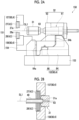
- Fig. 2A is a schematic side view illustrating the heating and expanding unit 150.
- Fig. 2B is a sectional view illustrating a state where the nozzle 31 has sealed the metal pipe material 40.
- the heating and expanding unit 150 includes the lower electrode 26, the upper electrode 27, an electrode mounting unit 151 in which the electrodes 26 and 27 are mounted, the nozzle 31, the drive mechanism 32, an elevating unit 152, and a unit base 153.
- the electrode mounting unit 151 includes an elevating frame 154 and electrode frames 156 and 157.
- the electrode frames 156 and 157 function as a part of a drive mechanism 60 that supports and moves each of the electrodes 26 and 27.
- the drive mechanism 32 drives the nozzle 31 and moves up and down together with the electrode mounting unit 151.
- the drive mechanism 32 includes a piston 61 that holds the nozzle 31, and a cylinder 62 that drives the piston.
- the elevating unit 152 includes an elevating frame base 64 attached to an upper surface of the unit base 153, and an elevating actuator 66 that applies an elevating operation to the elevating frame 154 of the electrode mounting unit 151 by using the elevating frame base 64.
- the elevating frame base 64 includes guide portions 64a and 64b that guide the elevating operation of the elevating frame 154 with respect to the unit base 153.
- the elevating unit 152 functions as a part of the drive mechanism 60 of the holding unit 4.
- the heating and expanding unit 150 includes a plurality of the unit bases 153 of which the upper surfaces have different inclination angles, and is allowed to collectively change and adjust inclination angles of the lower electrode 26, the upper electrode 27, the nozzle 31, the electrode mounting unit 151, the drive mechanism 32, and the elevating unit 152 by replacing the unit bases 153.
- the nozzle 31 is a cylindrical member into which the end portion of the metal pipe material 40 can be inserted.
- the nozzle 31 is supported by the drive mechanism 32 such that a center line of the nozzle 31 coincides with a reference line SL1.
- An inner diameter of a feed port 31a at an end portion of the nozzle 31 on the metal pipe material 40 side substantially coincides with an outer diameter of the metal pipe material 40 after expansion forming.
- the nozzle 31 supplies the high-pressure fluid from an internal flow path 63 to the metal pipe material 40.
- the high-pressure fluid include a gas.
- the cooling unit 7 is a mechanism that cools the forming die 2.
- the cooling unit 7 can rapidly cool the metal pipe material 40 when the expanded metal pipe material 40 comes into contact with the forming surface of the forming die 2, by cooling the forming die 2.
- the cooling unit 7 includes flow paths 36 formed inside the lower die 11 and the upper die 12 and a water circulation mechanism 37 that supplies a cooling water and causes the cooling water to circulate through the flow paths 36.
- the control unit 8 is a device that controls the entire forming device 1.
- the control unit 8 controls the drive mechanism 3, the holding unit 4, the heating unit 5, the fluid supply unit 6, and the cooling unit 7.
- the control unit 8 repeatedly performs the operation of forming the metal pipe material 40 using the forming die 2.
- control unit 8 controls, for example, a transport timing from a transport device, such as a robot arm, to dispose the metal pipe material 40 between the lower die 11 and the upper die 12 in an open state. Alternatively, a worker may manually dispose the metal pipe material 40 between the lower die 11 and the upper die 12. Additionally, the control unit 8 controls an actuator of the holding unit 4 and the like such that the metal pipe material 40 is supported by the lower electrodes 26 on both sides in the longitudinal direction, and then the upper electrodes 27 are lowered to interpose the metal pipe material 40. In addition, the control unit 8 controls the heating unit 5 to electrically heat the metal pipe material 40. Therefore, an axial current flows through the metal pipe material 40, and an electric resistance of the metal pipe material 40 itself causes the metal pipe material 40 itself to generate heat due to Joule heat.
- a transport timing from a transport device, such as a robot arm
- the control unit 8 controls the drive mechanism 3 to lower the upper die 12 and bring the upper die 12 close to the lower die 11, thereby closing the forming die 2. Meanwhile, the control unit 8 controls the fluid supply unit 6 to seal the opening portions of both ends of the metal pipe material 40 with the nozzle 31 and supply the fluid. Therefore, the metal pipe material 40 softened by the heating expands and comes into contact with the forming surface of the forming die 2. Then, the metal pipe material 40 is formed to follow a shape of the forming surface of the forming die 2.
- a part of the metal pipe material 40 is made to enter a gap between the lower die 11 and the upper die 12, and then die closing is further performed to crush the entering part to form a flange portion.
- the metal pipe material 40 comes into contact with the forming surface, the metal pipe material 40 is quenched by being rapidly cooled by using the forming die 2 cooled by the cooling unit 7.
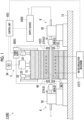
- the electrical heating device 100 includes the heating unit 5 and a measurement unit 70.
- the heating unit 5 includes two sets of the electrodes 26 and 27, the power supply 28, and the control unit 8.
- the measurement unit 70 measures a displacement amount of the metal pipe material 40.
- the measurement unit 70 includes a detector 71 that acquires information for measuring the displacement amount, and the control unit 8 that calculates the displacement amount based on the information acquired by the detector 71.
- the measurement unit 70 measures the displacement amount of the metal pipe material 40 in a non-contact manner.
- the measurement unit 70 adopts a camera that acquires an image of the metal pipe material 40, as the detector 71.
- the detector 71 captures the image of the metal pipe material 40 from a position spaced apart from the metal pipe material 40.
- the detector 71 acquires an image of an end portion 40a in which the displacement due to thermal expansion of the metal pipe material 40 is easily confirmed on the image (see Fig. 4 ).
- the disposition of the detector 71 is not particularly limited as long as the detector 71 does not interfere with other members, such as the forming die 2, and is disposed at a position at which the image of the end portion 40a can be easily acquired.
- the control unit 8 calculates the displacement amount of the metal pipe material 40 based on the image acquired by the detector 71.
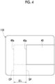
- Fig. 4 is a view illustrating an example of an image 110 acquired by the detector 71.
- a position of the end portion 40a of the metal pipe material 40 at the start of the heating is defined as a reference position SP.
- the metal pipe material 40 is thermally expanded, so that a length of the metal pipe material 40 increases.
- a position of the end portion 40a at a time when a time t has elapsed from the start of the heating is defined as a displacement position CP.
- the control unit 8 measures a dimension between the displacement position CP and the reference position SP from the image 110.
- the control unit 8 acquires the dimension as a displacement ⁇ L.
- the control unit 8 acquires the displacement amount of the metal pipe material 40 by calculating "displacement ⁇ L/time t".
- the displacement amount corresponds to a speed at which the end portion 40a extends due to the thermal expansion.
- Fig. 5 illustrates a graph G1 in which a relationship between the displacement amount and the time is plotted.
- a vertical axis indicates the displacement amount and a horizontal axis indicates the time.
- a graph G2 illustrates a relationship between the current and the time.
- the displacement amount increases from the start of the heating with a constant current to a time t1.
- the displacement amount is curved to protrude upward and draws a maximum point P1.
- the maximum point P1 is a change point indicating a change from a state where the displacement amount of the metal pipe material 40 increases to a state where the displacement amount of the metal pipe material 40 decreases.
- the displacement amount decreases from the maximum point P1 to a time t2.
- the displacement amount is curved to protrude downward and draws a minimum point P2.
- the displacement amount increases until the output of the power supply 28 is stopped after the minimum point P2.
- Fig. 6 illustrates a relationship between a change in a length due to the heating of a steel material and the temperature.
- the behavior of the dimensional change greatly changes with an austenite transformation temperature CT as a boundary.
- the austenite transformation temperature CT illustrated in Fig. 6 is approximately 720°C. Since the austenite transformation temperature CT is a physical property, the austenite transformation temperature CT is always constant regardless of a size or a power supply state of a heating target. The dimensional change after the transformation is constant. Therefore, in Fig.
- the change point indicating the change from a state where the displacement amount of the metal material increases to a state where the displacement amount of the metal material decreases indicates that the metal material is at the austenite transformation temperature or a temperature in the vicinity of the austenite transformation temperature regardless of the power supply state or the variations in the metal material.
- the temperature in the vicinity of the maximum point P1 in Fig. 5 is a temperature close to the austenite transformation temperature CT regardless of the size or the power supply state of the metal pipe material 40. Therefore, the temperature can be estimated by measuring the maximum point P1 via the measurement unit 70.
- the dimensional change after the transformation is constant.
- the metal pipe material can be heated to a desired target temperature.
- the maximum point P1 is adopted as the change point indicating a change from a state where the displacement amount of the metal pipe material 40 increases to a state where the displacement amount of the metal pipe material 40 decreases. It should be noted that any change point may be adopted as long as the change point indicates a change from a state where the displacement amount increases to a state where the displacement amount decreases.
- the maximum point P1 is a change point at which a state where the displacement amount increases is switched to a state where the displacement amount decreases, and is a maximum value in a range in the vicinity of the maximum point P1, but is not always a maximum value in the entire graph G1. That is, the displacement amount at the output stop may be larger than that of the maximum point P1.
- the measurement unit 70 measures the maximum point P1 at which a state where the displacement amount of the metal pipe material 40 increases is changed to a state where the displacement amount of the metal pipe material 40 decreases.
- the heating unit 5 performs the temperature control of the metal pipe material 40 based on the displacement amount of the metal pipe material 40 measured by the measurement unit 70.
- the heating unit 5 performs the temperature control of the metal pipe material 40 based on the measurement result of the maximum point P1 via the measurement unit 70.
- the heating unit 5 stops energizing the metal pipe material 40 after the predetermined time ⁇ t that has been determined in advance has elapsed from the measurement of the maximum point P1.
- the predetermined time ⁇ t is set in consideration of a time required to reach the target temperature from the austenite transformation temperature CT.
- Fig. 7 illustrates an example in a case where the measurement unit 70 measures the maximum point P1 by using the displacement amount.
- the control unit 8 of the measurement unit 70 calculates the displacement amount at a constant time interval tx. Before the time when reaching the maximum point P1, the control unit 8 measures the displacement amount that monotonically increases at the time interval tx. For example, at a time ta immediately before reaching the maximum point P1, the control unit 8 measures a large displacement amount. On the other hand, the displacement amount sharply decreases after the time when reaching the maximum point P1. Therefore, at a time tb following the time ta, the control unit 8 measures a value lower than a value of the displacement amount at the time ta.
- the control unit 8 measures the maximum point P1 in a case where the measured displacement amount is a value lower than that of the previous time and is a value equal to or lower than a threshold value TH.
- a measurement point P3 between the maximum point P1 and the minimum point P2 is measured by the control unit 8 at the time tb.
- the measurement point P3 it can be detected that the measurement point P3 is immediately after passing through the maximum point P1. In this way, the detection of the fact that the measurement point P3 is immediately after passing through the maximum point P1 is also included in the measurement of the maximum point P1 via the measurement unit 70.
- the control unit 8 stops the energization when the predetermined time ⁇ t has elapsed from the time tb at which the maximum point P1 has been measured.
- the time interval tx is not particularly limited, but the measurement accuracy of the maximum point P1 is higher as the time interval tx is smaller.
- the time interval tx is preferably smaller than the time interval between the maximum point P1 and the minimum point P2.
- the displacement amount does not decrease from immediately after the start of the heating to when the displacement amount reaches the maximum point P1. Therefore, a predetermined time from the start of the heating may be set as an ignoring period t3. In the ignoring period t3, the control unit 8 need not perform the calculation of the displacement amount or the comparison with the previous value.
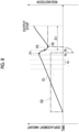
- Fig. 8 illustrates an example in a case where the measurement unit 70 measures the maximum point P1 by using acceleration.
- a graph G3 illustrates a relationship between the acceleration and the time.
- the control unit 8 of the measurement unit 70 calculates the acceleration at the constant time interval tx.
- the acceleration is acceleration of the extension of the metal pipe material 40.
- the control unit 8 calculates the acceleration by differentiating the displacement amount.
- the control unit 8 measures constant acceleration at the time interval tx.
- the acceleration sharply decreases from positive to negative.
- the control unit 8 measures positive acceleration at the time ta immediately before reaching the maximum point P1.
- the acceleration is negative. Therefore, the control unit 8 measures the negative acceleration at the time tb after the time ta.
- the control unit 8 measures the maximum point P1. Next, the control unit 8 stops the energization when the predetermined time ⁇ t has elapsed from the time tb at which the maximum point P1 has been measured.
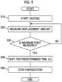
- the heating unit 5 causes the current to flow through the metal pipe material 40 to heat the metal pipe material 40 (step S10: heating process), and then the measurement unit 70 measures the displacement amount of the metal pipe material 40 (step S20: measurement process).
- the measurement unit 70 determines whether or not the maximum point P1 is measured (S30: measurement process). In a case where it is determined in step S30 that the maximum point P1 is not measured, the measurement unit 70 returns to step S20 and measures the displacement amount again at a predetermined timing.
- step S30 the heating unit 5 waits for a predetermined time ⁇ t that has been determined in advance (step S40: heating process). During this time, the heating unit 5 continues the electrical heating. Next, the heating unit 5 stops the electrical heating after the predetermined time ⁇ t has elapsed (step S50: heating process). In this way, in the heating process, the temperature control of the metal pipe material 40 is performed based on the displacement amount of the metal pipe material 40 measured in the measurement process.
- the electrical heating device 100 includes the measurement unit 70 that measures the displacement amount of the metal pipe material 40.
- the displacement amount of the metal pipe material 40 has a portion indicating the same behavior in a relationship with the temperature regardless of the power supply state or the variations in the metal pipe material 40. Therefore, the heating unit 5 performs the temperature control of the metal pipe material 40 based on the displacement amount of the metal pipe material 40 measured by the measurement unit 70. Therefore, the heating unit 5 can perform the temperature control with high accuracy regardless of the power supply state or the variations in the metal pipe material 40, based on the displacement amount of the metal pipe material 40.
- the measurement unit 70 may measure the change point (maximum point P1) indicating a change from a state where the displacement amount of the metal pipe material 40 increases to a state where the displacement amount of the metal pipe material 40 decreases, and the heating unit 5 may perform the temperature control of the metal pipe material 40 based on the measurement result of the change point (maximum point P1) via the measurement unit 70.
- the displacement amount greatly decreases with an austenite transformation temperature as a boundary.
- the change point indicating the change from a state where the displacement amount of the metal pipe material 40 increases to a state where the displacement amount of the metal pipe material 40 decreases indicates that the metal pipe material 40 is at the austenite transformation temperature or a temperature in the vicinity of the austenite transformation temperature regardless of the power supply state or the variations in the metal pipe material 40. Therefore, the heating unit 5 can perform the temperature control with high accuracy based on the measurement result of the maximum point P1.
- the heating unit 5 may stop energizing the metal pipe material 40 after the predetermined time has elapsed from the measurement of the maximum point P1.
- the displacement amount after the austenite transformation temperature increases at a constant rate regardless of the power supply state or the variations in the metal material. Therefore, the heating unit 5 can stop the energization at a desired target temperature after the predetermined time has elapsed from the measurement of the maximum point P1.
- the measurement unit 70 may measure the displacement amount of the metal pipe material 40 in a non-contact manner. In this case, the measurement unit 70 can measure the displacement amount from a position spaced apart from the high-temperature metal pipe material 40.
- the forming device 1 includes the electrical heating device 100, and forms the heated metal pipe material 40.
- the electrical heating method includes the heating process of causing the current to flow through the metal pipe material 40 to heat the metal pipe material 40, and the measurement process of measuring the displacement amount of the metal pipe material 40, in which in the heating process, the temperature control of the metal pipe material 40 is performed based on the displacement amount of the metal pipe material 40 measured in the measurement process.
- the camera is adopted as the detector, but another non-contact type sensor, such as a laser measuring instrument, may be used.
- a contact type measuring instrument may also be used as the detector.
- the forming device need only be any forming device that heats the metal material, and a forming device using a hot stamping method may be adopted.
- the metal material is a plate material.
- An electrical heating device including: a heating unit that causes a current to flow through a metal material to heat the metal material; and a measurement unit that measures a displacement amount of the metal material, in which the heating unit performs temperature control of the metal material based on the displacement amount of the metal material measured by the measurement unit.
- the electrical heating device in which the measurement unit measures a change point indicating a change from a state where the displacement amount of the metal material increases to a state where the displacement amount of the metal material decreases, and the heating unit performs the temperature control of the metal material based on a measurement result of the change point via the measurement unit.
- the electrical heating device in which the heating unit stops energizing the metal material after a predetermined time has elapsed from the measurement of the change point.
- the electrical heating device according to any one of aspects 1 to 3, in which the measurement unit measures the displacement amount of the metal material in a non-contact manner.
- a forming device including: the electrical heating device according to any one of aspects 1 to 4, in which the forming device forms the heated metal material.
- An electrical heating method including: a heating process of causing a current to flow through a metal material to heat the metal material; and a measurement process of measuring a displacement amount of the metal material, in which in the heating process, temperature control of the metal material is performed based on the displacement amount of the metal material measured in the measurement process.
Landscapes
- Engineering & Computer Science (AREA)
- Chemical & Material Sciences (AREA)
- Mechanical Engineering (AREA)
- Physics & Mathematics (AREA)
- Thermal Sciences (AREA)
- Crystallography & Structural Chemistry (AREA)
- Materials Engineering (AREA)
- Metallurgy (AREA)
- Organic Chemistry (AREA)
- Fluid Mechanics (AREA)
- Manufacturing & Machinery (AREA)
- Shaping Metal By Deep-Drawing, Or The Like (AREA)
- Injection Moulding Of Plastics Or The Like (AREA)
- Extrusion Moulding Of Plastics Or The Like (AREA)
Abstract
Description
- The present disclosure relates to an electrical heating device, a forming device, and an electrical heating method.
- In the related art, a forming device that forms a heated metal material has been known. For example,
PTL 1 discloses a forming device including a die including a pair of a lower die and an upper die, a gas supply unit that supplies a gas into a metal pipe material held between the dies, and a heating unit that heats the metal pipe material by electrical heating. - [PTL 1]
Japanese Unexamined Patent Publication No. 2009-220141 - Here, the electrical heating device performs temperature control of electrical heating. Examples of an electrical heating method include a method of performing energization for a certain time set in advance and a method of plotting a relationship between a resistance value and a temperature for each member in advance to estimate a temperature from a correlation relationship thereof. However, since there are always variations in a shape or a power supply state for each member, a high-accuracy temperature control result cannot be obtained in these methods. In particular, in a case where the metal material is large and a large current is required, the influence of the variations for each metal material is very large. Additionally, there is a method of performing the temperature control by measuring a change point of resistance accompanying austenite transformation, but it is necessary to measure the current and the voltage in order to measure the resistance. However, the measurement of the current and the voltage is likely to be affected by noise due to the energization, and high-accuracy measurement may not be performed.
- Therefore, an object of the present disclosure is to provide an electrical heating device, a forming device, and an electrical heating method that can accurately perform temperature control regardless of a power supply state and variations in a metal material.
- According to an aspect of the present disclosure, there is provided an electrical heating device including a heating unit that causes a current to flow through a metal material to heat the metal material, and a measurement unit that measures a displacement amount of the metal material, in which the heating unit performs temperature control of the metal material based on the displacement amount of the metal material measured by the measurement unit.
- The electrical heating device includes the measurement unit that measures the displacement amount of the metal material. The displacement amount of the metal material has a portion indicating the same behavior in a relationship with the temperature regardless of the power supply state or the variations in the metal material. Therefore, the heating unit performs the temperature control of the metal material based on the displacement amount of the metal material measured by the measurement unit. Therefore, the heating unit can perform the temperature control with high accuracy regardless of the power supply state or the variations in the metal material, based on the displacement amount of the metal material.
- The measurement unit may measure a change point indicating a change from a state where the displacement amount of the metal material increases to a state where the displacement amount of the metal material decreases, and the heating unit may perform the temperature control of the metal material based on a measurement result of the change point via the measurement unit. The displacement amount greatly decreases with an austenite transformation temperature as a boundary. Therefore, the change point indicating the change from a state where the displacement amount of the metal material increases to a state where the displacement amount of the metal material decreases indicates that the metal material is at the austenite transformation temperature or a temperature in the vicinity of the austenite transformation temperature regardless of the power supply state or the variations in the metal material. Therefore, the heating unit can perform the temperature control with high accuracy based on the measurement result of the change point.
- The heating unit may stop energizing the metal material after a predetermined time has elapsed from the measurement of the change point. The displacement amount after the austenite transformation temperature increases at a constant rate regardless of the power supply state or the variations in the metal material. Therefore, the heating unit can stop the energization at a desired target temperature after the predetermined time has elapsed from the measurement of the change point.
- The measurement unit may measure the displacement amount of the metal material in a non-contact manner. In this case, the measurement unit can measure the displacement amount from a position spaced apart from a high-temperature metal material.
- According to another aspect of the present disclosure, there is provided a forming device including the electrical heating device described above, in which the forming device forms the heated metal material.
- With the forming device, it is possible to obtain the actions and effects having the same meaning as those of the above-described electrical heating device.
- According to still another aspect of the present disclosure, there is provided an electrical heating method including: a heating process of causing a current to flow through a metal material to heat the metal material, and a measurement process of measuring a displacement amount of the metal material, in which in the heating process, temperature control of the metal material is performed based on the displacement amount of the metal material measured in the measurement process.
- With the electrical heating method, it is possible to obtain the actions and effects having the same meaning as those of the above-described electrical heating device.
- According to the present disclosure, it is possible to provide the electrical heating device, the forming device, and the electrical heating method that can accurately perform the temperature control regardless of the power supply state and the variations in the metal material.
-
-
Fig. 1 is a schematic configuration view illustrating a forming device according to an embodiment of the present disclosure. -
Fig. 2A is a schematic side view illustrating a heating and expanding unit.Fig. 2B is a sectional view illustrating a state where a nozzle has sealed a metal pipe material. -
Fig. 3 is a schematic view illustrating an electrical heating device according to the present embodiment. -
Fig. 4 is a view illustrating an example of an image acquired by a detector. -
Fig. 5 is a graph in which a relationship between a displacement amount and a time is plotted. -
Fig. 6 is a graph illustrating a relationship between a change in a length due to heating of a steel material and a temperature. -
Fig. 7 is a graph illustrating an example of a method in which a measurement unit measures a maximum point. -
Fig. 8 is a graph illustrating an example of the method in which the measurement unit measures the maximum point. -
Fig. 9 is a flowchart illustrating an electrical heating method according to the embodiment of the present disclosure. - Hereinafter, a preferred embodiment of a forming device according to the present disclosure will be described with reference to the drawings. In the drawings, the same reference numerals will be given to the same portions or equivalent portions, and the redundant description thereof will be omitted.
-
Fig. 1 is a schematic configuration view of a formingdevice 1 including anelectrical heating device 100 according to the present embodiment. As illustrated inFig. 1 , the formingdevice 1 is a device that forms a metal pipe having a hollow shape by blow forming. In the present embodiment, the formingdevice 1 is installed on a horizontal plane. The formingdevice 1 includes a forming die 2, adrive mechanism 3, a holding unit 4, aheating unit 5, afluid supply unit 6, acooling unit 7, and acontrol unit 8. In the present specification, a metal pipe material 40 (metal material) refers to a hollow article before the completion of forming via the formingdevice 1. Themetal pipe material 40 is a steel-type pipe material that can be quenched. In addition, in a horizontal direction, a direction in which themetal pipe material 40 extends during the forming may be referred to as a "longitudinal direction", and a direction perpendicular to the longitudinal direction may be referred to as a "width direction". - The forming die 2 is a die that forms a metal pipe from the
metal pipe material 40, and includes alower die 11 and an upper die 12 that face each other in an up-down direction. Thelower die 11 and the upper die 12 are configured by blocks made of steel. Each of thelower die 11 and the upper die 12 is provided with a recessed part in which themetal pipe material 40 is accommodated. In a state where thelower die 11 and the upper die 12 are in close contact with each other (die closed state), the respective recessed parts form a space having a target shape in which the metal pipe material is to be formed. Therefore, surfaces of the respective recessed parts are forming surfaces of the formingdie 2. Thelower die 11 is fixed to abase stage 13 via a die holder or the like. The upper die 12 is fixed to a slide of thedrive mechanism 3 via a die holder or the like. - The
drive mechanism 3 is a mechanism that moves at least one of thelower die 11 and the upper die 12. InFig. 1 , thedrive mechanism 3 has a configuration of moving only the upper die 12. Thedrive mechanism 3 includes aslide 21 that moves the upper die 12 such that thelower die 11 and the upper die 12 are joined together, a pull-back cylinder 22 as an actuator that generates a force for pulling theslide 21 upward, amain cylinder 23 as a drive source that downward-pressurizes theslide 21, and adrive source 24 that applies a driving force to themain cylinder 23. - The holding unit 4 is a mechanism that holds the
metal pipe material 40 disposed between thelower die 11 and the upper die 12. The holding unit 4 includes a lower electrode 26 and an upper electrode 27 that hold themetal pipe material 40 on one end side in the longitudinal direction of the formingdie 2, and a lower electrode 26 and an upper electrode 27 that hold themetal pipe material 40 on the other end side in the longitudinal direction of the formingdie 2. The lower electrodes 26 and the upper electrodes 27 on both sides in the longitudinal direction hold themetal pipe material 40 by interposing vicinities of end portions of themetal pipe material 40 from the up-down direction. Upper surfaces of the lower electrodes 26 and lower surfaces of the upper electrodes 27 are formed with groove portions having a shape corresponding to an outer peripheral surface of themetal pipe material 40. Drive mechanisms (not illustrated) are provided in the lower electrodes 26 and the upper electrodes 27 and are movable independently of each other in the up-down direction. - The
heating unit 5 heats themetal pipe material 40. Theheating unit 5 is a mechanism that heats themetal pipe material 40 by energizing themetal pipe material 40. Theheating unit 5 heats themetal pipe material 40 in a state where themetal pipe material 40 is spaced apart from thelower die 11 and the upper die 12, between thelower die 11 and the upper die 12. Theheating unit 5 includes the lower electrodes 26 and the upper electrodes 27 on both sides in the longitudinal direction, apower supply 28 that causes a current to flow through themetal pipe material 40 via the electrodes 26 and 27, and thecontrol unit 8 that controls thepower supply 28. Theheating unit 5 may be disposed in a preceding process of the formingdevice 1 to perform heating externally. - The
fluid supply unit 6 is a mechanism that supplies a high-pressure fluid into themetal pipe material 40 held between thelower die 11 and the upper die 12. Thefluid supply unit 6 supplies the high-pressure fluid into themetal pipe material 40 that has been brought into a high-temperature state by being heated by theheating unit 5, to expand themetal pipe material 40. Thefluid supply units 6 are provided on both end sides of the formingdie 2 in the longitudinal direction. Thefluid supply unit 6 includes anozzle 31 that supplies the fluid from an opening portion of an end portion of themetal pipe material 40 to an inside of themetal pipe material 40, adrive mechanism 32 that moves thenozzle 31 forward and backward with respect to the opening portion of themetal pipe material 40, and asupply source 33 that supplies the high-pressure fluid into themetal pipe material 40 via thenozzle 31. Thedrive mechanism 32 brings thenozzle 31 into close contact with the end portion of themetal pipe material 40 in a state in which sealing performance is secured during the fluid supply and exhaust, and causes thenozzle 31 to be spaced apart from the end portion of themetal pipe material 40 in other cases. Thefluid supply unit 6 may supply a gas such as high-pressure air and an inert gas, as the fluid. Additionally, thefluid supply unit 6 may include theheating unit 5 together with the holding unit 4 including a mechanism that moves themetal pipe material 40 in the up-down direction as the same device. - Components of the holding unit 4, the
heating unit 5, and thefluid supply unit 6 may be configured as a unitized heating and expandingunit 150.Fig. 2A is a schematic side view illustrating the heating and expandingunit 150.Fig. 2B is a sectional view illustrating a state where thenozzle 31 has sealed themetal pipe material 40. - As illustrated in
Fig. 2A , the heating and expandingunit 150 includes the lower electrode 26, the upper electrode 27, anelectrode mounting unit 151 in which the electrodes 26 and 27 are mounted, thenozzle 31, thedrive mechanism 32, an elevating unit 152, and aunit base 153. Theelectrode mounting unit 151 includes an elevatingframe 154 and electrode frames 156 and 157. The electrode frames 156 and 157 function as a part of a drive mechanism 60 that supports and moves each of the electrodes 26 and 27. Thedrive mechanism 32 drives thenozzle 31 and moves up and down together with theelectrode mounting unit 151. Thedrive mechanism 32 includes apiston 61 that holds thenozzle 31, and acylinder 62 that drives the piston. The elevating unit 152 includes an elevatingframe base 64 attached to an upper surface of theunit base 153, and an elevatingactuator 66 that applies an elevating operation to the elevatingframe 154 of theelectrode mounting unit 151 by using the elevatingframe base 64. The elevatingframe base 64 includesguide portions frame 154 with respect to theunit base 153. The elevating unit 152 functions as a part of the drive mechanism 60 of the holding unit 4. The heating and expandingunit 150 includes a plurality of the unit bases 153 of which the upper surfaces have different inclination angles, and is allowed to collectively change and adjust inclination angles of the lower electrode 26, the upper electrode 27, thenozzle 31, theelectrode mounting unit 151, thedrive mechanism 32, and the elevating unit 152 by replacing the unit bases 153. - The
nozzle 31 is a cylindrical member into which the end portion of themetal pipe material 40 can be inserted. Thenozzle 31 is supported by thedrive mechanism 32 such that a center line of thenozzle 31 coincides with a reference line SL1. An inner diameter of afeed port 31a at an end portion of thenozzle 31 on themetal pipe material 40 side substantially coincides with an outer diameter of themetal pipe material 40 after expansion forming. In this state, thenozzle 31 supplies the high-pressure fluid from aninternal flow path 63 to themetal pipe material 40. Examples of the high-pressure fluid include a gas. - Returning to
Fig. 1 , thecooling unit 7 is a mechanism that cools the formingdie 2. Thecooling unit 7 can rapidly cool themetal pipe material 40 when the expandedmetal pipe material 40 comes into contact with the forming surface of the formingdie 2, by cooling the formingdie 2. Thecooling unit 7 includesflow paths 36 formed inside thelower die 11 and the upper die 12 and awater circulation mechanism 37 that supplies a cooling water and causes the cooling water to circulate through theflow paths 36. - The
control unit 8 is a device that controls the entire formingdevice 1. Thecontrol unit 8 controls thedrive mechanism 3, the holding unit 4, theheating unit 5, thefluid supply unit 6, and thecooling unit 7. Thecontrol unit 8 repeatedly performs the operation of forming themetal pipe material 40 using the formingdie 2. - Specifically, the
control unit 8 controls, for example, a transport timing from a transport device, such as a robot arm, to dispose themetal pipe material 40 between thelower die 11 and the upper die 12 in an open state. Alternatively, a worker may manually dispose themetal pipe material 40 between thelower die 11 and the upper die 12. Additionally, thecontrol unit 8 controls an actuator of the holding unit 4 and the like such that themetal pipe material 40 is supported by the lower electrodes 26 on both sides in the longitudinal direction, and then the upper electrodes 27 are lowered to interpose themetal pipe material 40. In addition, thecontrol unit 8 controls theheating unit 5 to electrically heat themetal pipe material 40. Therefore, an axial current flows through themetal pipe material 40, and an electric resistance of themetal pipe material 40 itself causes themetal pipe material 40 itself to generate heat due to Joule heat. - The
control unit 8 controls thedrive mechanism 3 to lower the upper die 12 and bring the upper die 12 close to thelower die 11, thereby closing the formingdie 2. Meanwhile, thecontrol unit 8 controls thefluid supply unit 6 to seal the opening portions of both ends of themetal pipe material 40 with thenozzle 31 and supply the fluid. Therefore, themetal pipe material 40 softened by the heating expands and comes into contact with the forming surface of the formingdie 2. Then, themetal pipe material 40 is formed to follow a shape of the forming surface of the formingdie 2. In addition, in a case where a metal pipe with a flange is formed, a part of themetal pipe material 40 is made to enter a gap between thelower die 11 and the upper die 12, and then die closing is further performed to crush the entering part to form a flange portion. When themetal pipe material 40 comes into contact with the forming surface, themetal pipe material 40 is quenched by being rapidly cooled by using the formingdie 2 cooled by thecooling unit 7. - Hereinafter, the
electrical heating device 100 according to the present embodiment will be described in detail with reference toFig. 3 . As illustrated inFig. 3 , theelectrical heating device 100 includes theheating unit 5 and ameasurement unit 70. As described above, theheating unit 5 includes two sets of the electrodes 26 and 27, thepower supply 28, and thecontrol unit 8. - The
measurement unit 70 measures a displacement amount of themetal pipe material 40. Themeasurement unit 70 includes adetector 71 that acquires information for measuring the displacement amount, and thecontrol unit 8 that calculates the displacement amount based on the information acquired by thedetector 71. Themeasurement unit 70 measures the displacement amount of themetal pipe material 40 in a non-contact manner. In the present embodiment, themeasurement unit 70 adopts a camera that acquires an image of themetal pipe material 40, as thedetector 71. Thedetector 71 captures the image of themetal pipe material 40 from a position spaced apart from themetal pipe material 40. Thedetector 71 acquires an image of anend portion 40a in which the displacement due to thermal expansion of themetal pipe material 40 is easily confirmed on the image (seeFig. 4 ). The disposition of thedetector 71 is not particularly limited as long as thedetector 71 does not interfere with other members, such as the formingdie 2, and is disposed at a position at which the image of theend portion 40a can be easily acquired. Thecontrol unit 8 calculates the displacement amount of themetal pipe material 40 based on the image acquired by thedetector 71. -
Fig. 4 is a view illustrating an example of animage 110 acquired by thedetector 71. As illustrated inFig. 4 , a position of theend portion 40a of themetal pipe material 40 at the start of the heating is defined as a reference position SP. When the heating is started, themetal pipe material 40 is thermally expanded, so that a length of themetal pipe material 40 increases. A position of theend portion 40a at a time when a time t has elapsed from the start of the heating is defined as a displacement position CP. Thecontrol unit 8 measures a dimension between the displacement position CP and the reference position SP from theimage 110. Thecontrol unit 8 acquires the dimension as a displacement ΔL. Then, thecontrol unit 8 acquires the displacement amount of themetal pipe material 40 by calculating "displacement ΔL/time t". The displacement amount corresponds to a speed at which theend portion 40a extends due to the thermal expansion. -
Fig. 5 illustrates a graph G1 in which a relationship between the displacement amount and the time is plotted. In the graph G1, a vertical axis indicates the displacement amount and a horizontal axis indicates the time. In addition, a graph G2 illustrates a relationship between the current and the time. The displacement amount increases from the start of the heating with a constant current to a time t1. The displacement amount is curved to protrude upward and draws a maximum point P1. The maximum point P1 is a change point indicating a change from a state where the displacement amount of themetal pipe material 40 increases to a state where the displacement amount of themetal pipe material 40 decreases. The displacement amount decreases from the maximum point P1 to a time t2. The displacement amount is curved to protrude downward and draws a minimum point P2. The displacement amount increases until the output of thepower supply 28 is stopped after the minimum point P2. - Here,
Fig. 6 illustrates a relationship between a change in a length due to the heating of a steel material and the temperature. As illustrated inFig. 6 , the behavior of the dimensional change greatly changes with an austenite transformation temperature CT as a boundary. The austenite transformation temperature CT illustrated inFig. 6 is approximately 720°C. Since the austenite transformation temperature CT is a physical property, the austenite transformation temperature CT is always constant regardless of a size or a power supply state of a heating target. The dimensional change after the transformation is constant. Therefore, inFig. 6 , the change point indicating the change from a state where the displacement amount of the metal material increases to a state where the displacement amount of the metal material decreases indicates that the metal material is at the austenite transformation temperature or a temperature in the vicinity of the austenite transformation temperature regardless of the power supply state or the variations in the metal material. The temperature in the vicinity of the maximum point P1 inFig. 5 is a temperature close to the austenite transformation temperature CT regardless of the size or the power supply state of themetal pipe material 40. Therefore, the temperature can be estimated by measuring the maximum point P1 via themeasurement unit 70. The dimensional change after the transformation is constant. Therefore, when themeasurement unit 70 measures the maximum point P1 and the heating is performed for a predetermined time Δt that has been determined in advance, the metal pipe material can be heated to a desired target temperature. In the present embodiment, the maximum point P1 is adopted as the change point indicating a change from a state where the displacement amount of themetal pipe material 40 increases to a state where the displacement amount of themetal pipe material 40 decreases. It should be noted that any change point may be adopted as long as the change point indicates a change from a state where the displacement amount increases to a state where the displacement amount decreases. The maximum point P1 is a change point at which a state where the displacement amount increases is switched to a state where the displacement amount decreases, and is a maximum value in a range in the vicinity of the maximum point P1, but is not always a maximum value in the entire graph G1. That is, the displacement amount at the output stop may be larger than that of the maximum point P1. - From the above, the
measurement unit 70 measures the maximum point P1 at which a state where the displacement amount of themetal pipe material 40 increases is changed to a state where the displacement amount of themetal pipe material 40 decreases. In addition, theheating unit 5 performs the temperature control of themetal pipe material 40 based on the displacement amount of themetal pipe material 40 measured by themeasurement unit 70. Theheating unit 5 performs the temperature control of themetal pipe material 40 based on the measurement result of the maximum point P1 via themeasurement unit 70. Specifically, theheating unit 5 stops energizing themetal pipe material 40 after the predetermined time Δt that has been determined in advance has elapsed from the measurement of the maximum point P1. The predetermined time Δt is set in consideration of a time required to reach the target temperature from the austenite transformation temperature CT. - A specific temperature control content will be described with reference to
Figs. 7 and8 .Fig. 7 illustrates an example in a case where themeasurement unit 70 measures the maximum point P1 by using the displacement amount. As illustrated inFig. 7 , thecontrol unit 8 of themeasurement unit 70 calculates the displacement amount at a constant time interval tx. Before the time when reaching the maximum point P1, thecontrol unit 8 measures the displacement amount that monotonically increases at the time interval tx. For example, at a time ta immediately before reaching the maximum point P1, thecontrol unit 8 measures a large displacement amount. On the other hand, the displacement amount sharply decreases after the time when reaching the maximum point P1. Therefore, at a time tb following the time ta, thecontrol unit 8 measures a value lower than a value of the displacement amount at the time ta. - The
control unit 8 measures the maximum point P1 in a case where the measured displacement amount is a value lower than that of the previous time and is a value equal to or lower than a threshold value TH. A measurement point P3 between the maximum point P1 and the minimum point P2 is measured by thecontrol unit 8 at the time tb. However, in a case where the measurement point P3 is measured, it can be detected that the measurement point P3 is immediately after passing through the maximum point P1. In this way, the detection of the fact that the measurement point P3 is immediately after passing through the maximum point P1 is also included in the measurement of the maximum point P1 via themeasurement unit 70. Next, thecontrol unit 8 stops the energization when the predetermined time Δt has elapsed from the time tb at which the maximum point P1 has been measured. The time interval tx is not particularly limited, but the measurement accuracy of the maximum point P1 is higher as the time interval tx is smaller. The time interval tx is preferably smaller than the time interval between the maximum point P1 and the minimum point P2. The displacement amount does not decrease from immediately after the start of the heating to when the displacement amount reaches the maximum point P1. Therefore, a predetermined time from the start of the heating may be set as an ignoring period t3. In the ignoring period t3, thecontrol unit 8 need not perform the calculation of the displacement amount or the comparison with the previous value. -
Fig. 8 illustrates an example in a case where themeasurement unit 70 measures the maximum point P1 by using acceleration. A graph G3 illustrates a relationship between the acceleration and the time. As illustrated inFig. 8 , thecontrol unit 8 of themeasurement unit 70 calculates the acceleration at the constant time interval tx. The acceleration is acceleration of the extension of themetal pipe material 40. Thecontrol unit 8 calculates the acceleration by differentiating the displacement amount. Before the time when reaching the maximum point P1, thecontrol unit 8 measures constant acceleration at the time interval tx. At the maximum point P1, the acceleration sharply decreases from positive to negative. For example, thecontrol unit 8 measures positive acceleration at the time ta immediately before reaching the maximum point P1. On the other hand, at the timing immediately after the maximum point P1, the acceleration is negative. Therefore, thecontrol unit 8 measures the negative acceleration at the time tb after the time ta. - In a case where the measured acceleration is negative, the
control unit 8 measures the maximum point P1. Next, thecontrol unit 8 stops the energization when the predetermined time Δt has elapsed from the time tb at which the maximum point P1 has been measured. - Hereinafter, an electrical heating method according to the present embodiment will be described with reference to
Fig. 9 . - First, the
heating unit 5 causes the current to flow through themetal pipe material 40 to heat the metal pipe material 40 (step S10: heating process), and then themeasurement unit 70 measures the displacement amount of the metal pipe material 40 (step S20: measurement process). Next, themeasurement unit 70 determines whether or not the maximum point P1 is measured (S30: measurement process). In a case where it is determined in step S30 that the maximum point P1 is not measured, themeasurement unit 70 returns to step S20 and measures the displacement amount again at a predetermined timing. - In a case where it is determined in step S30 that the maximum point P1 is measured, the
heating unit 5 waits for a predetermined time Δt that has been determined in advance (step S40: heating process).
During this time, theheating unit 5 continues the electrical heating. Next, theheating unit 5 stops the electrical heating after the predetermined time Δt has elapsed (step S50: heating process). In this way, in the heating process, the temperature control of themetal pipe material 40 is performed based on the displacement amount of themetal pipe material 40 measured in the measurement process. - Hereinafter, the actions and effects of the
electrical heating device 100, the formingdevice 1, and the electrical heating method according to the present embodiment will be described. - The
electrical heating device 100 includes themeasurement unit 70 that measures the displacement amount of themetal pipe material 40. The displacement amount of themetal pipe material 40 has a portion indicating the same behavior in a relationship with the temperature regardless of the power supply state or the variations in themetal pipe material 40. Therefore, theheating unit 5 performs the temperature control of themetal pipe material 40 based on the displacement amount of themetal pipe material 40 measured by themeasurement unit 70. Therefore, theheating unit 5 can perform the temperature control with high accuracy regardless of the power supply state or the variations in themetal pipe material 40, based on the displacement amount of themetal pipe material 40. - The
measurement unit 70 may measure the change point (maximum point P1) indicating a change from a state where the displacement amount of themetal pipe material 40 increases to a state where the displacement amount of themetal pipe material 40 decreases, and theheating unit 5 may perform the temperature control of themetal pipe material 40 based on the measurement result of the change point (maximum point P1) via themeasurement unit 70. The displacement amount greatly decreases with an austenite transformation temperature as a boundary. Therefore, the change point indicating the change from a state where the displacement amount of themetal pipe material 40 increases to a state where the displacement amount of themetal pipe material 40 decreases indicates that themetal pipe material 40 is at the austenite transformation temperature or a temperature in the vicinity of the austenite transformation temperature regardless of the power supply state or the variations in themetal pipe material 40. Therefore, theheating unit 5 can perform the temperature control with high accuracy based on the measurement result of the maximum point P1. - The
heating unit 5 may stop energizing themetal pipe material 40 after the predetermined time has elapsed from the measurement of the maximum point P1. The displacement amount after the austenite transformation temperature increases at a constant rate regardless of the power supply state or the variations in the metal material. Therefore, theheating unit 5 can stop the energization at a desired target temperature after the predetermined time has elapsed from the measurement of the maximum point P1. - The
measurement unit 70 may measure the displacement amount of themetal pipe material 40 in a non-contact manner. In this case, themeasurement unit 70 can measure the displacement amount from a position spaced apart from the high-temperaturemetal pipe material 40. - The forming
device 1 according to the present embodiment includes theelectrical heating device 100, and forms the heatedmetal pipe material 40. - With the forming
device 1, it is possible to obtain the actions and effects having the same meaning as those of theelectrical heating device 100. - The electrical heating method according to the present embodiment includes the heating process of causing the current to flow through the
metal pipe material 40 to heat themetal pipe material 40, and the measurement process of measuring the displacement amount of themetal pipe material 40, in which in the heating process, the temperature control of themetal pipe material 40 is performed based on the displacement amount of themetal pipe material 40 measured in the measurement process. - With the electrical heating method, it is possible to obtain the actions and effects having the same meaning as those of the
electrical heating device 100. - The present disclosure is not limited to the above-described embodiment described above.
- In the above-described embodiment, the camera is adopted as the detector, but another non-contact type sensor, such as a laser measuring instrument, may be used. A contact type measuring instrument may also be used as the detector.
- The forming device need only be any forming device that heats the metal material, and a forming device using a hot stamping method may be adopted. In this case, the metal material is a plate material.
- An electrical heating device including: a heating unit that causes a current to flow through a metal material to heat the metal material; and a measurement unit that measures a displacement amount of the metal material, in which the heating unit performs temperature control of the metal material based on the displacement amount of the metal material measured by the measurement unit.
- The electrical heating device according to
aspect 1, in which the measurement unit measures a change point indicating a change from a state where the displacement amount of the metal material increases to a state where the displacement amount of the metal material decreases, and the heating unit performs the temperature control of the metal material based on a measurement result of the change point via the measurement unit. - The electrical heating device according to
aspect 2, in which the heating unit stops energizing the metal material after a predetermined time has elapsed from the measurement of the change point. - The electrical heating device according to any one of
aspects 1 to 3, in which the measurement unit measures the displacement amount of the metal material in a non-contact manner. - A forming device including: the electrical heating device according to any one of
aspects 1 to 4, in which the forming device forms the heated metal material. - An electrical heating method including: a heating process of causing a current to flow through a metal material to heat the metal material; and a measurement process of measuring a displacement amount of the metal material, in which in the heating process, temperature control of the metal material is performed based on the displacement amount of the metal material measured in the measurement process.
-
- 1 forming device
- 5 heating unit
- 40 metal pipe material (metal material)
- 70 measurement unit
- 100 electrical heating device
Claims (6)
- An electrical heating device comprising:a heating unit that causes a current to flow through a metal material to heat the metal material; anda measurement unit that measures a displacement amount of the metal material,wherein the heating unit performs temperature control of the metal material based on the displacement amount of the metal material measured by the measurement unit.
- The electrical heating device according to claim 1,wherein the measurement unit measures a change point indicating a change from a state where the displacement amount of the metal material increases to a state where the displacement amount of the metal material decreases, andthe heating unit performs the temperature control of the metal material based on a measurement result of the change point via the measurement unit.
- The electrical heating device according to claim 2,
wherein the heating unit stops energizing the metal material after a predetermined time has elapsed from the measurement of the change point. - The electrical heating device according to claim 1,
wherein the measurement unit measures the displacement amount of the metal material in a non-contact manner. - A forming device comprising:the electrical heating device according to claim 1,wherein the forming device forms the heated metal material.
- An electrical heating method comprising:a heating process of causing a current to flow through a metal material to heat the metal material; anda measurement process of measuring a displacement amount of the metal material,wherein in the heating process, temperature control of the metal material is performed based on the displacement amount of the metal material measured in the measurement process.
Applications Claiming Priority (2)
| Application Number | Priority Date | Filing Date | Title |
|---|---|---|---|
| JP2022022656 | 2022-02-17 | ||
| PCT/JP2023/003663 WO2023157684A1 (en) | 2022-02-17 | 2023-02-03 | Electrical heating device, molding device, and electrical heating method |
Publications (2)
| Publication Number | Publication Date |
|---|---|
| EP4480594A1 true EP4480594A1 (en) | 2024-12-25 |
| EP4480594A4 EP4480594A4 (en) | 2025-06-18 |
Family
ID=87578531
Family Applications (1)
| Application Number | Title | Priority Date | Filing Date |
|---|---|---|---|
| EP23756211.1A Pending EP4480594A4 (en) | 2022-02-17 | 2023-02-03 | Electrical heating device, molding device, and electrical heating method |
Country Status (7)
| Country | Link |
|---|---|
| US (1) | US20240334552A1 (en) |
| EP (1) | EP4480594A4 (en) |
| JP (1) | JPWO2023157684A1 (en) |
| KR (1) | KR20240150411A (en) |
| CN (1) | CN118383080A (en) |
| CA (1) | CA3237576A1 (en) |
| WO (1) | WO2023157684A1 (en) |
Family Cites Families (7)
| Publication number | Priority date | Publication date | Assignee | Title |
|---|---|---|---|---|
| JP3761820B2 (en) * | 2001-09-04 | 2006-03-29 | アイシン高丘株式会社 | Metal member forming method |
| JP2009034716A (en) * | 2007-08-03 | 2009-02-19 | Toyota Motor Corp | Material inflow measuring device |
| JP2009220141A (en) | 2008-03-14 | 2009-10-01 | Marujun Co Ltd | Method and apparatus for manufacturing pipe product |
| CN102806248A (en) * | 2012-08-06 | 2012-12-05 | 哈尔滨工业大学 | Device and method for testing real-time changes of fillet radius along with internal pressure in internal high-pressure forming process |
| KR102360267B1 (en) * | 2017-03-30 | 2022-02-07 | 스미도모쥬기가이고교 가부시키가이샤 | molding equipment |
| KR102384804B1 (en) * | 2017-03-30 | 2022-04-07 | 스미도모쥬기가이고교 가부시키가이샤 | molding system |
| JP2022078380A (en) * | 2019-03-28 | 2022-05-25 | 住友重機械工業株式会社 | Electric conduction heating device |
-
2023
- 2023-02-03 WO PCT/JP2023/003663 patent/WO2023157684A1/en not_active Ceased
- 2023-02-03 JP JP2024501295A patent/JPWO2023157684A1/ja active Pending
- 2023-02-03 CN CN202380014006.1A patent/CN118383080A/en active Pending
- 2023-02-03 KR KR1020247011287A patent/KR20240150411A/en active Pending
- 2023-02-03 CA CA3237576A patent/CA3237576A1/en active Pending
- 2023-02-03 EP EP23756211.1A patent/EP4480594A4/en active Pending
-
2024
- 2024-06-11 US US18/739,350 patent/US20240334552A1/en active Pending
Also Published As
| Publication number | Publication date |
|---|---|
| US20240334552A1 (en) | 2024-10-03 |
| WO2023157684A1 (en) | 2023-08-24 |
| CA3237576A1 (en) | 2023-08-24 |
| KR20240150411A (en) | 2024-10-15 |
| CN118383080A (en) | 2024-07-23 |
| JPWO2023157684A1 (en) | 2023-08-24 |
| EP4480594A4 (en) | 2025-06-18 |
Similar Documents
| Publication | Publication Date | Title |
|---|---|---|
| JP6285082B2 (en) | Molding apparatus and molding method | |
| JP6449104B2 (en) | Molding equipment | |
| US11253900B2 (en) | Forming apparatus | |
| US20240334552A1 (en) | Electrical heating device, forming device, and electrical heating method | |
| JP7474756B2 (en) | Molding System | |
| EP4487975A1 (en) | Electric heating device, molding device, and electric heating method | |
| US20240300000A1 (en) | Forming device | |
| US11998969B2 (en) | Forming system | |
| CN112739472B (en) | Expansion molding device | |
| US12358037B2 (en) | Forming device and forming method | |
| EP4438196A1 (en) | Molding device and molding method | |
| JP2019038039A (en) | Molding apparatus | |
| JP7538757B2 (en) | Electrical heating system and electrode | |
| US20260084200A1 (en) | Forming device | |
| US20250222508A1 (en) | Forming device | |
| CA3162758C (en) | Forming device and forming method | |
| JP2020095775A (en) | Electric heating device |
Legal Events
| Date | Code | Title | Description |
|---|---|---|---|
| STAA | Information on the status of an ep patent application or granted ep patent |
Free format text: STATUS: THE INTERNATIONAL PUBLICATION HAS BEEN MADE |
|
| PUAI | Public reference made under article 153(3) epc to a published international application that has entered the european phase |
Free format text: ORIGINAL CODE: 0009012 |
|
| STAA | Information on the status of an ep patent application or granted ep patent |
Free format text: STATUS: REQUEST FOR EXAMINATION WAS MADE |
|
| 17P | Request for examination filed |
Effective date: 20240430 |
|
| AK | Designated contracting states |
Kind code of ref document: A1 Designated state(s): AL AT BE BG CH CY CZ DE DK EE ES FI FR GB GR HR HU IE IS IT LI LT LU LV MC ME MK MT NL NO PL PT RO RS SE SI SK SM TR |
|
| DAV | Request for validation of the european patent (deleted) | ||
| DAX | Request for extension of the european patent (deleted) | ||
| STAA | Information on the status of an ep patent application or granted ep patent |
Free format text: STATUS: EXAMINATION IS IN PROGRESS |
|
| A4 | Supplementary search report drawn up and despatched |
Effective date: 20250519 |
|
| RIC1 | Information provided on ipc code assigned before grant |
Ipc: C21D 8/10 20060101ALI20250513BHEP Ipc: C21D 1/40 20060101ALI20250513BHEP Ipc: H05B 3/00 20060101ALI20250513BHEP Ipc: B21D 26/033 20110101AFI20250513BHEP |
|
| 17Q | First examination report despatched |
Effective date: 20250603 |