EP4480569A1 - Reactor module - Google Patents
Reactor module Download PDFInfo
- Publication number
- EP4480569A1 EP4480569A1 EP23756360.6A EP23756360A EP4480569A1 EP 4480569 A1 EP4480569 A1 EP 4480569A1 EP 23756360 A EP23756360 A EP 23756360A EP 4480569 A1 EP4480569 A1 EP 4480569A1
- Authority
- EP
- European Patent Office
- Prior art keywords
- reactor
- membrane
- source gas
- water vapor
- generated
- Prior art date
- Legal status (The legal status is an assumption and is not a legal conclusion. Google has not performed a legal analysis and makes no representation as to the accuracy of the status listed.)
- Pending
Links
Images


Classifications
-
- B—PERFORMING OPERATIONS; TRANSPORTING
- B01—PHYSICAL OR CHEMICAL PROCESSES OR APPARATUS IN GENERAL
- B01J—CHEMICAL OR PHYSICAL PROCESSES, e.g. CATALYSIS OR COLLOID CHEMISTRY; THEIR RELEVANT APPARATUS
- B01J19/00—Chemical, physical or physico-chemical processes in general; Their relevant apparatus
- B01J19/24—Stationary reactors without moving elements inside
- B01J19/2475—Membrane reactors
-
- B—PERFORMING OPERATIONS; TRANSPORTING
- B01—PHYSICAL OR CHEMICAL PROCESSES OR APPARATUS IN GENERAL
- B01D—SEPARATION
- B01D53/00—Separation of gases or vapours; Recovering vapours of volatile solvents from gases; Chemical or biological purification of waste gases, e.g. engine exhaust gases, smoke, fumes, flue gases, aerosols
- B01D53/22—Separation of gases or vapours; Recovering vapours of volatile solvents from gases; Chemical or biological purification of waste gases, e.g. engine exhaust gases, smoke, fumes, flue gases, aerosols by diffusion
-
- B—PERFORMING OPERATIONS; TRANSPORTING
- B01—PHYSICAL OR CHEMICAL PROCESSES OR APPARATUS IN GENERAL
- B01D—SEPARATION
- B01D61/00—Processes of separation using semi-permeable membranes, e.g. dialysis, osmosis or ultrafiltration; Apparatus, accessories or auxiliary operations specially adapted therefor
- B01D61/58—Multistep processes
-
- B—PERFORMING OPERATIONS; TRANSPORTING
- B01—PHYSICAL OR CHEMICAL PROCESSES OR APPARATUS IN GENERAL
- B01J—CHEMICAL OR PHYSICAL PROCESSES, e.g. CATALYSIS OR COLLOID CHEMISTRY; THEIR RELEVANT APPARATUS
- B01J19/00—Chemical, physical or physico-chemical processes in general; Their relevant apparatus
- B01J19/0006—Controlling or regulating processes
- B01J19/0013—Controlling the temperature of the process
-
- B—PERFORMING OPERATIONS; TRANSPORTING
- B01—PHYSICAL OR CHEMICAL PROCESSES OR APPARATUS IN GENERAL
- B01J—CHEMICAL OR PHYSICAL PROCESSES, e.g. CATALYSIS OR COLLOID CHEMISTRY; THEIR RELEVANT APPARATUS
- B01J19/00—Chemical, physical or physico-chemical processes in general; Their relevant apparatus
- B01J19/24—Stationary reactors without moving elements inside
- B01J19/2445—Stationary reactors without moving elements inside placed in parallel
-
- B—PERFORMING OPERATIONS; TRANSPORTING
- B01—PHYSICAL OR CHEMICAL PROCESSES OR APPARATUS IN GENERAL
- B01J—CHEMICAL OR PHYSICAL PROCESSES, e.g. CATALYSIS OR COLLOID CHEMISTRY; THEIR RELEVANT APPARATUS
- B01J19/00—Chemical, physical or physico-chemical processes in general; Their relevant apparatus
- B01J19/24—Stationary reactors without moving elements inside
- B01J19/245—Stationary reactors without moving elements inside placed in series
-
- B—PERFORMING OPERATIONS; TRANSPORTING
- B01—PHYSICAL OR CHEMICAL PROCESSES OR APPARATUS IN GENERAL
- B01J—CHEMICAL OR PHYSICAL PROCESSES, e.g. CATALYSIS OR COLLOID CHEMISTRY; THEIR RELEVANT APPARATUS
- B01J8/00—Chemical or physical processes in general, conducted in the presence of fluids and solid particles; Apparatus for such processes
- B01J8/008—Details of the reactor or of the particulate material; Processes to increase or to retard the rate of reaction
- B01J8/009—Membranes, e.g. feeding or removing reactants or products to or from the catalyst bed through a membrane
-
- B—PERFORMING OPERATIONS; TRANSPORTING
- B01—PHYSICAL OR CHEMICAL PROCESSES OR APPARATUS IN GENERAL
- B01J—CHEMICAL OR PHYSICAL PROCESSES, e.g. CATALYSIS OR COLLOID CHEMISTRY; THEIR RELEVANT APPARATUS
- B01J8/00—Chemical or physical processes in general, conducted in the presence of fluids and solid particles; Apparatus for such processes
- B01J8/02—Chemical or physical processes in general, conducted in the presence of fluids and solid particles; Apparatus for such processes with stationary particles, e.g. in fixed beds
- B01J8/04—Chemical or physical processes in general, conducted in the presence of fluids and solid particles; Apparatus for such processes with stationary particles, e.g. in fixed beds the fluid passing successively through two or more beds
-
- B—PERFORMING OPERATIONS; TRANSPORTING
- B01—PHYSICAL OR CHEMICAL PROCESSES OR APPARATUS IN GENERAL
- B01J—CHEMICAL OR PHYSICAL PROCESSES, e.g. CATALYSIS OR COLLOID CHEMISTRY; THEIR RELEVANT APPARATUS
- B01J8/00—Chemical or physical processes in general, conducted in the presence of fluids and solid particles; Apparatus for such processes
- B01J8/02—Chemical or physical processes in general, conducted in the presence of fluids and solid particles; Apparatus for such processes with stationary particles, e.g. in fixed beds
- B01J8/04—Chemical or physical processes in general, conducted in the presence of fluids and solid particles; Apparatus for such processes with stationary particles, e.g. in fixed beds the fluid passing successively through two or more beds
- B01J8/0496—Heating or cooling the reactor
-
- B—PERFORMING OPERATIONS; TRANSPORTING
- B01—PHYSICAL OR CHEMICAL PROCESSES OR APPARATUS IN GENERAL
- B01J—CHEMICAL OR PHYSICAL PROCESSES, e.g. CATALYSIS OR COLLOID CHEMISTRY; THEIR RELEVANT APPARATUS
- B01J8/00—Chemical or physical processes in general, conducted in the presence of fluids and solid particles; Apparatus for such processes
- B01J8/02—Chemical or physical processes in general, conducted in the presence of fluids and solid particles; Apparatus for such processes with stationary particles, e.g. in fixed beds
- B01J8/06—Chemical or physical processes in general, conducted in the presence of fluids and solid particles; Apparatus for such processes with stationary particles, e.g. in fixed beds in tube reactors; the solid particles being arranged in tubes
-
- C—CHEMISTRY; METALLURGY
- C07—ORGANIC CHEMISTRY
- C07B—GENERAL METHODS OF ORGANIC CHEMISTRY; APPARATUS THEREFOR
- C07B61/00—Other general methods
-
- C—CHEMISTRY; METALLURGY
- C07—ORGANIC CHEMISTRY
- C07C—ACYCLIC OR CARBOCYCLIC COMPOUNDS
- C07C29/00—Preparation of compounds having hydroxy or O-metal groups bound to a carbon atom not belonging to a six-membered aromatic ring
- C07C29/15—Preparation of compounds having hydroxy or O-metal groups bound to a carbon atom not belonging to a six-membered aromatic ring by reduction of oxides of carbon exclusively
- C07C29/151—Preparation of compounds having hydroxy or O-metal groups bound to a carbon atom not belonging to a six-membered aromatic ring by reduction of oxides of carbon exclusively with hydrogen or hydrogen-containing gases
- C07C29/152—Preparation of compounds having hydroxy or O-metal groups bound to a carbon atom not belonging to a six-membered aromatic ring by reduction of oxides of carbon exclusively with hydrogen or hydrogen-containing gases characterised by the reactor used
-
- C—CHEMISTRY; METALLURGY
- C07—ORGANIC CHEMISTRY
- C07C—ACYCLIC OR CARBOCYCLIC COMPOUNDS
- C07C31/00—Saturated compounds having hydroxy or O-metal groups bound to acyclic carbon atoms
- C07C31/02—Monohydroxylic acyclic alcohols
- C07C31/04—Methanol
-
- B—PERFORMING OPERATIONS; TRANSPORTING
- B01—PHYSICAL OR CHEMICAL PROCESSES OR APPARATUS IN GENERAL
- B01J—CHEMICAL OR PHYSICAL PROCESSES, e.g. CATALYSIS OR COLLOID CHEMISTRY; THEIR RELEVANT APPARATUS
- B01J2208/00—Processes carried out in the presence of solid particles; Reactors therefor
- B01J2208/00008—Controlling the process
- B01J2208/00017—Controlling the temperature
-
- B—PERFORMING OPERATIONS; TRANSPORTING
- B01—PHYSICAL OR CHEMICAL PROCESSES OR APPARATUS IN GENERAL
- B01J—CHEMICAL OR PHYSICAL PROCESSES, e.g. CATALYSIS OR COLLOID CHEMISTRY; THEIR RELEVANT APPARATUS
- B01J2208/00—Processes carried out in the presence of solid particles; Reactors therefor
- B01J2208/02—Processes carried out in the presence of solid particles; Reactors therefor with stationary particles
- B01J2208/023—Details
- B01J2208/024—Particulate material
- B01J2208/025—Two or more types of catalyst
-
- B—PERFORMING OPERATIONS; TRANSPORTING
- B01—PHYSICAL OR CHEMICAL PROCESSES OR APPARATUS IN GENERAL
- B01J—CHEMICAL OR PHYSICAL PROCESSES, e.g. CATALYSIS OR COLLOID CHEMISTRY; THEIR RELEVANT APPARATUS
- B01J2219/00—Chemical, physical or physico-chemical processes in general; Their relevant apparatus
- B01J2219/00049—Controlling or regulating processes
- B01J2219/00164—Controlling or regulating processes controlling the flow
-
- B—PERFORMING OPERATIONS; TRANSPORTING
- B01—PHYSICAL OR CHEMICAL PROCESSES OR APPARATUS IN GENERAL
- B01J—CHEMICAL OR PHYSICAL PROCESSES, e.g. CATALYSIS OR COLLOID CHEMISTRY; THEIR RELEVANT APPARATUS
- B01J2219/00—Chemical, physical or physico-chemical processes in general; Their relevant apparatus
- B01J2219/24—Stationary reactors without moving elements inside
- B01J2219/2401—Reactors comprising multiple separate flow channels
- B01J2219/2402—Monolithic-type reactors
- B01J2219/2423—Separation means, e.g. membrane inside the reactor
Definitions
- the present invention relates to a reactor module.
- Patent Literature 1 discloses a membrane reactor including: a flow path through which a source gas flows; a catalyst disposed in the flow path; and a separation membrane that allows water vapor, which is one of products, to pass therethrough.
- Patent Literature 1 JP 2018-008940A
- An object of the present invention is to provide a reactor module that can improve the cost performance of a separation membrane.
- a reactor module includes a pre-reactor and a membrane reactor disposed downstream of the pre-reactor, the membrane reactor including a separation membrane.
- the pre-reactor an intermediate gas is generated from a source gas containing hydrogen and carbon oxide, the intermediate gas containing a liquid fuel, water vapor, and residual source gas.
- the membrane reactor the liquid fuel and water vapor are generated from the residual source gas.
- the separation membrane allows the water vapor contained in the intermediate gas and the water vapor generated from the residual source gas to pass therethrough.
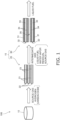
- FIG. 1 is a schematic diagram showing the configuration of the reactor system 100.
- the reactor system 100 includes a source gas source 10 and a reactor module 15.
- the reactor module 15 includes a pre-reactor 20 and a membrane reactor 30.
- the pre-reactor 20 and the membrane reactor 30 may be housed in separate pressure-resistant containers or may be housed together in a single pressure-resistant container. It is more preferable to house the pre-reactor 20 and the membrane reactor 30 in separate pressure-resistant containers, since temperatures of the pre-reactor 20 and the membrane reactor 30 can be controlled individually in such a case.
- FIG. 1 schematically shows cross sections of the pre-reactor 20 and the membrane reactor 30.
- the source gas source 10 is disposed upstream of the pre-reactor 20.
- a source gas is stored in the source gas source 10.
- the source gas source 10 supplies the source gas to the pre-reactor 20.
- the source gas contains at least hydrogen and carbon oxide. At least one of carbon monoxide and carbon dioxide can be used as the carbon oxide.
- the source gas may be a so-called synthesis gas (syngas).
- the pre-reactor 20 is disposed downstream of the source gas source 10.
- the pre-reactor 20 is disposed upstream of the membrane reactor 30.
- the source gas is supplied from the source gas source 10 to the pre-reactor 20.
- a conversion reaction for converting the source gas into a liquid fuel is carried out in the pre-reactor 20, and an intermediate gas is generated as a result of the conversion reaction.
- the pre-reactor 20 supplies the intermediate gas to the membrane reactor 30.
- the liquid fuel is a fuel that is in a liquid state at normal temperature and normal pressure or a fuel that can be liquefied at normal temperature in a pressurized state.
- fuels that are in a liquid state at normal temperature and normal pressure include methanol, ethanol, a liquid fuel represented by C n H 2(m-2n) (m is an integer smaller than 90, and n is an integer smaller than 30), and a mixture of these.
- the liquid fuel generated in the pre-reactor 20 is in a gaseous state when it is generated, and remains in the gaseous state at least until the liquid fuel flows out from the pre-reactor 20.
- fuels that can be liquefied at normal temperature in a pressurized state include propane, butane, and a mixture of these.
- reaction formula (1) for the synthesis of methanol through catalytic hydrogenation of a source gas containing hydrogen and carbon dioxide in the presence of a catalyst is expressed as follows. CO 2 +3H 2 ⁇ CH 3 OH+H 2 O (1)
- the intermediate gas contains the liquid fuel generated as a result of the conversion reaction, water vapor, which is one of the products of the conversion reaction, and residual source gas that was not used in the conversion reaction.
- the content of water vapor in the intermediate gas can be determined depending on the permeability of a separation membrane 34 included in the membrane reactor 30, which will be described later.
- the content of the residual source gas in the intermediate gas can be determined depending on the conversion efficiency in the membrane reactor 30.
- an operating temperature of the pre-reactor 20 is higher than an operating temperature of the membrane reactor 30. Since the pre-reactor 20 does not include a separation membrane, the operating temperature of the pre-reactor 20 can be set to a temperature suitable for the catalytic activity of a first catalyst 23 without consideration being given to the heat resistance of the separation membrane. The operating temperature of the pre-reactor 20 can be set to 180°C or higher and 350°C or lower, for example. The operating temperature of the pre-reactor 20 is the temperature of the intermediate gas flowing inside a portion adjacent to the pre-reactor 20 (hereinafter referred to as the "portion near the pre-reactor") in a connection pipe (not shown) connecting the pre-reactor 20 to the membrane reactor 30.
- the operating temperature of the pre-reactor 20 can be measured with use of a thermocouple, a resistance thermometer, a thermistor, or the like.
- a thermocouple When it is difficult to measure the temperature of the intermediate gas flowing inside the portion near the pre-reactor, it is also possible to set a measurement site on the outer surface of the portion near the pre-reactor, measure the temperature of the measurement site in a state where the influence of ambient temperature, etc., is reduced by covering the portion with a thermal insulation material, and estimate the temperature of the intermediate gas flowing inside the portion based on the measured temperature.
- the pre-reactor 20 includes reaction tubes 21, first flow paths 22, and the first catalyst 23.
- the pre-reactor 20 does not include a separation membrane.
- the first flow paths 22 are formed inside the reaction tubes 21.
- the source gas is caused to flow through the first flow paths 22.
- the first catalyst 23 is disposed in the first flow paths 22.
- the first catalyst 23 promotes the conversion reaction described above.
- the intermediate gas generated as a result of the conversion reaction is collected from the first flow paths 22.
- the pre-reactor 20 according to the present embodiment includes three first flow paths 22, it is sufficient that the pre-reactor 20 includes at least one first flow path 22.
- a known catalyst suitable for the conversion reaction for obtaining the desired liquid fuel can be used as the first catalyst 23.
- the first catalyst 23 include metal catalysts (copper, palladium, etc.), oxide catalysts (zinc oxide, zirconia, gallium oxide, etc.), and composites of these (copper-zinc oxide, copper-zinc oxide-alumina, copper-zinc oxide-chromium oxide-alumina, copper-cobalt-titania, and these catalysts modified with palladium, etc.).
- the configuration of the pre-reactor 20 can be changed as necessary. It is possible to use, as the pre-reactor 20, a well-known reactor that does not include a separation membrane (for example, JP 2005-298413A or JP 2010-13422A ).
- the membrane reactor 30 is disposed downstream of the pre-reactor 20.
- the intermediate gas is supplied from the pre-reactor 20 to the membrane reactor 30.
- the membrane reactor 30 separates water vapor generated in the pre-reactor 20 and water vapor generated in the membrane reactor 30 while carrying out a conversion reaction for converting the residual source gas contained in the intermediate gas into the liquid fuel (see reaction formula (1) shown above).
- a conversion reaction for converting the residual source gas contained in the intermediate gas into the liquid fuel
- the liquid fuel generated in the membrane reactor 30 is in a gaseous state when it is generated, and remains in the gaseous state at least until the liquid fuel flows out from the membrane reactor 30.
- the operating temperature of the membrane reactor 30 is set with consideration given to the heat resistance of the separation membrane 34.
- the operating temperature of the membrane reactor 30 may be lower than the operating temperature of the pre-reactor 20.
- the operating temperature of the membrane reactor 30 can be set to 160°C or higher and 300°C or lower, for example.
- the operating temperature of the membrane reactor 30 is the temperature of the liquid fuel flowing inside a portion adjacent to the membrane reactor 30 (hereinafter referred to as the "portion near the membrane reactor") in a discharge pipe (not shown) for discharging the liquid fuel to the outside from the membrane reactor 30.
- the operating temperature of the membrane reactor 30 can be measured with use of a thermocouple, a resistance thermometer, a thermistor, or the like.
- the membrane reactor 30 includes a porous support 31, second flow paths 32, a second catalyst 33, the separation membrane 34, and a third flow path 35.
- the porous support 31 is constituted by a porous material.
- a ceramic material, a metallic material, a resin material, or the like can be used as the porous material, and a ceramic material is particularly favorable.
- At least one of alumina (Al 2 O 3 ), titania (TiO 2 ), mullite (Al 2 O 3 ⁇ SiO 2 ), potsherd, and cordierite (Mg 2 Al 4 Si 5 O 18 ) can be used as an aggregate for the ceramic material, for example.
- At least one of titania, mullite, easily sinterable alumina, silica, glass frit, a clay mineral, and easily sinterable cordierite can be used as an inorganic binder for the ceramic material, for example.
- the ceramic material does not necessarily need to contain an inorganic binder.
- the second flow paths 32 are formed in the porous support 31.
- the second flow paths 32 extend through the porous support 31. Accordingly, both ends of each second flow path 32 are open in the outer surface of the porous support 31.
- the second flow paths 32 correspond to a space on a non-permeation side of the separation membrane 34.
- the intermediate gas is caused to flow through the second flow paths 32.
- the intermediate gas contains the liquid fuel generated in the pre-reactor 20, water vapor generated in the pre-reactor 20, and residual source gas that was not used in the conversion reaction in the pre-reactor 20.
- the membrane reactor 30 according to the present embodiment includes two second flow paths 32, but it is sufficient that the membrane reactor 30 includes at least one second flow path 32.
Landscapes
- Chemical & Material Sciences (AREA)
- Organic Chemistry (AREA)
- Chemical Kinetics & Catalysis (AREA)
- Engineering & Computer Science (AREA)
- Analytical Chemistry (AREA)
- General Chemical & Material Sciences (AREA)
- Oil, Petroleum & Natural Gas (AREA)
- Water Supply & Treatment (AREA)
- Separation Using Semi-Permeable Membranes (AREA)
Abstract
Description
- The present invention relates to a reactor module.
- In recent years, membrane reactors capable of improving conversion efficiency by separating products in a conversion reaction for converting a source gas containing hydrogen and carbon oxide into a liquid fuel (methanol, ethanol, etc.) have been developed.
- Patent Literature 1 discloses a membrane reactor including: a flow path through which a source gas flows; a catalyst disposed in the flow path; and a separation membrane that allows water vapor, which is one of products, to pass therethrough.
- Patent Literature 1:
JP 2018-008940A - In the membrane reactor described in Patent Literature 1, the amount of water vapor generated in an upstream region of the flow path is small, and the separation membrane cannot be fully utilized, so the cost performance of the separation membrane is low.
- An object of the present invention is to provide a reactor module that can improve the cost performance of a separation membrane.
- A reactor module according to the present invention includes a pre-reactor and a membrane reactor disposed downstream of the pre-reactor, the membrane reactor including a separation membrane. In the pre-reactor, an intermediate gas is generated from a source gas containing hydrogen and carbon oxide, the intermediate gas containing a liquid fuel, water vapor, and residual source gas. In the membrane reactor, the liquid fuel and water vapor are generated from the residual source gas. The separation membrane allows the water vapor contained in the intermediate gas and the water vapor generated from the residual source gas to pass therethrough.
- According to the present invention, it is possible to provide a reactor module that can improve the cost performance of a separation membrane.
-
-
FIG. 1 is a schematic diagram of a reactor module according to an embodiment. -
FIG. 2 is a schematic diagram of a reactor module according to a variation. -
FIG. 3 is a schematic diagram of a reactor module according to a variation. - The following describes a
reactor system 100 according to an embodiment.FIG. 1 is a schematic diagram showing the configuration of thereactor system 100. Thereactor system 100 includes asource gas source 10 and areactor module 15. - The
reactor module 15 includes a pre-reactor 20 and amembrane reactor 30. The pre-reactor 20 and themembrane reactor 30 may be housed in separate pressure-resistant containers or may be housed together in a single pressure-resistant container. It is more preferable to house the pre-reactor 20 and themembrane reactor 30 in separate pressure-resistant containers, since temperatures of the pre-reactor 20 and themembrane reactor 30 can be controlled individually in such a case.FIG. 1 schematically shows cross sections of the pre-reactor 20 and themembrane reactor 30. - The
source gas source 10 is disposed upstream of the pre-reactor 20. A source gas is stored in thesource gas source 10. Thesource gas source 10 supplies the source gas to the pre-reactor 20. The source gas contains at least hydrogen and carbon oxide. At least one of carbon monoxide and carbon dioxide can be used as the carbon oxide. The source gas may be a so-called synthesis gas (syngas). - The pre-reactor 20 is disposed downstream of the
source gas source 10. The pre-reactor 20 is disposed upstream of themembrane reactor 30. The source gas is supplied from thesource gas source 10 to the pre-reactor 20. A conversion reaction for converting the source gas into a liquid fuel is carried out in the pre-reactor 20, and an intermediate gas is generated as a result of the conversion reaction. The pre-reactor 20 supplies the intermediate gas to themembrane reactor 30. - The liquid fuel is a fuel that is in a liquid state at normal temperature and normal pressure or a fuel that can be liquefied at normal temperature in a pressurized state. Examples of fuels that are in a liquid state at normal temperature and normal pressure include methanol, ethanol, a liquid fuel represented by CnH2(m-2n) (m is an integer smaller than 90, and n is an integer smaller than 30), and a mixture of these. The liquid fuel generated in the pre-reactor 20 is in a gaseous state when it is generated, and remains in the gaseous state at least until the liquid fuel flows out from the pre-reactor 20. Examples of fuels that can be liquefied at normal temperature in a pressurized state include propane, butane, and a mixture of these.
- For example, a reaction formula (1) for the synthesis of methanol through catalytic hydrogenation of a source gas containing hydrogen and carbon dioxide in the presence of a catalyst is expressed as follows.
CO2+3H2 ⇔ CH3OH+H2O (1)
- The intermediate gas contains the liquid fuel generated as a result of the conversion reaction, water vapor, which is one of the products of the conversion reaction, and residual source gas that was not used in the conversion reaction. The content of water vapor in the intermediate gas can be determined depending on the permeability of a
separation membrane 34 included in themembrane reactor 30, which will be described later. The content of the residual source gas in the intermediate gas can be determined depending on the conversion efficiency in themembrane reactor 30. - It is preferable that an operating temperature of the pre-reactor 20 is higher than an operating temperature of the
membrane reactor 30. Since the pre-reactor 20 does not include a separation membrane, the operating temperature of the pre-reactor 20 can be set to a temperature suitable for the catalytic activity of afirst catalyst 23 without consideration being given to the heat resistance of the separation membrane. The operating temperature of the pre-reactor 20 can be set to 180°C or higher and 350°C or lower, for example. The operating temperature of the pre-reactor 20 is the temperature of the intermediate gas flowing inside a portion adjacent to the pre-reactor 20 (hereinafter referred to as the "portion near the pre-reactor") in a connection pipe (not shown) connecting the pre-reactor 20 to themembrane reactor 30. The operating temperature of the pre-reactor 20 can be measured with use of a thermocouple, a resistance thermometer, a thermistor, or the like. When it is difficult to measure the temperature of the intermediate gas flowing inside the portion near the pre-reactor, it is also possible to set a measurement site on the outer surface of the portion near the pre-reactor, measure the temperature of the measurement site in a state where the influence of ambient temperature, etc., is reduced by covering the portion with a thermal insulation material, and estimate the temperature of the intermediate gas flowing inside the portion based on the measured temperature. - The pre-reactor 20 includes
reaction tubes 21,first flow paths 22, and thefirst catalyst 23. The pre-reactor 20 does not include a separation membrane. - The
first flow paths 22 are formed inside thereaction tubes 21. The source gas is caused to flow through thefirst flow paths 22. Thefirst catalyst 23 is disposed in thefirst flow paths 22. Thefirst catalyst 23 promotes the conversion reaction described above. The intermediate gas generated as a result of the conversion reaction is collected from thefirst flow paths 22. Although the pre-reactor 20 according to the present embodiment includes threefirst flow paths 22, it is sufficient that the pre-reactor 20 includes at least onefirst flow path 22. - A known catalyst suitable for the conversion reaction for obtaining the desired liquid fuel can be used as the
first catalyst 23. Examples of thefirst catalyst 23 include metal catalysts (copper, palladium, etc.), oxide catalysts (zinc oxide, zirconia, gallium oxide, etc.), and composites of these (copper-zinc oxide, copper-zinc oxide-alumina, copper-zinc oxide-chromium oxide-alumina, copper-cobalt-titania, and these catalysts modified with palladium, etc.). - Although a configuration of the pre-reactor 20 has been described, the configuration of the pre-reactor 20 can be changed as necessary. It is possible to use, as the pre-reactor 20, a well-known reactor that does not include a separation membrane (for example,
JP 2005-298413A JP 2010-13422A - The
membrane reactor 30 is disposed downstream of the pre-reactor 20. The intermediate gas is supplied from the pre-reactor 20 to themembrane reactor 30. Themembrane reactor 30 separates water vapor generated in the pre-reactor 20 and water vapor generated in themembrane reactor 30 while carrying out a conversion reaction for converting the residual source gas contained in the intermediate gas into the liquid fuel (see reaction formula (1) shown above). By carrying out the conversion reaction while separating a product as described above, it is possible to shift the reaction equilibrium of the above formula (1) to the product side by utilizing an equilibrium shift effect. Note that the liquid fuel generated in themembrane reactor 30 is in a gaseous state when it is generated, and remains in the gaseous state at least until the liquid fuel flows out from themembrane reactor 30. - The operating temperature of the
membrane reactor 30 is set with consideration given to the heat resistance of theseparation membrane 34. The operating temperature of themembrane reactor 30 may be lower than the operating temperature of the pre-reactor 20. The operating temperature of themembrane reactor 30 can be set to 160°C or higher and 300°C or lower, for example. The operating temperature of themembrane reactor 30 is the temperature of the liquid fuel flowing inside a portion adjacent to the membrane reactor 30 (hereinafter referred to as the "portion near the membrane reactor") in a discharge pipe (not shown) for discharging the liquid fuel to the outside from themembrane reactor 30. The operating temperature of themembrane reactor 30 can be measured with use of a thermocouple, a resistance thermometer, a thermistor, or the like. When it is difficult to measure the temperature of the liquid fuel flowing inside the portion near the membrane reactor, it is also possible to set a measurement site on the outer surface of the portion near the membrane reactor, measure the temperature of the measurement site in a state where the influence of ambient temperature, etc., is reduced by covering the portion with a thermal insulation material, and estimate the temperature of the liquid fuel flowing inside the portion based on the measured temperature. - The
membrane reactor 30 includes aporous support 31,second flow paths 32, asecond catalyst 33, theseparation membrane 34, and athird flow path 35. - The
porous support 31 is constituted by a porous material. A ceramic material, a metallic material, a resin material, or the like can be used as the porous material, and a ceramic material is particularly favorable. At least one of alumina (Al2O3), titania (TiO2), mullite (Al2O3·SiO2), potsherd, and cordierite (Mg2Al4Si5O18) can be used as an aggregate for the ceramic material, for example. At least one of titania, mullite, easily sinterable alumina, silica, glass frit, a clay mineral, and easily sinterable cordierite can be used as an inorganic binder for the ceramic material, for example. However, the ceramic material does not necessarily need to contain an inorganic binder. - The
second flow paths 32 are formed in theporous support 31. Thesecond flow paths 32 extend through theporous support 31. Accordingly, both ends of eachsecond flow path 32 are open in the outer surface of theporous support 31. Thesecond flow paths 32 correspond to a space on a non-permeation side of theseparation membrane 34. - The intermediate gas is caused to flow through the
second flow paths 32. The intermediate gas contains the liquid fuel generated in the pre-reactor 20, water vapor generated in the pre-reactor 20, and residual source gas that was not used in the conversion reaction in the pre-reactor 20. Themembrane reactor 30 according to the present embodiment includes twosecond flow paths 32, but it is sufficient that themembrane reactor 30 includes at least onesecond flow path 32. - The
second catalyst 33 is disposed in thesecond flow paths 32. A known catalyst suitable for the conversion reaction for obtaining the desired liquid fuel can be used as thesecond catalyst 33. Thesecond catalyst 33 promotes the conversion reaction. Examples of thesecond catalyst 33 include metal catalysts (copper, palladium, etc.), oxide catalysts (zinc oxide, zirconia, gallium oxide, etc.), and composites of these (copper-zinc oxide, copper-zinc oxide-alumina, copper-zinc oxide-chromium oxide-alumina, copper-cobalt-titania, and these catalysts modified with palladium, etc.). - Here, the
second catalyst 33 is used for the conversion reaction for converting the residual source gas contained in the intermediate gas. Therefore, the burden on thesecond catalyst 33 can be reduced when compared with a case where thesecond catalyst 33 is directly used for the conversion reaction for converting the whole amount of source gas. As described above, when thefirst catalyst 23 included in the pre-reactor 20 takes on a part of the burden required for the conversion reaction for converting the source gas, it is possible to reduce the burden on thesecond catalyst 33 included in themembrane reactor 30, thereby extending the service life of thesecond catalyst 33. - The
separation membrane 34 is supported by theporous support 31. Theseparation membrane 34 surrounds thesecond flow paths 32. Theseparation membrane 34 is disposed between thesecond flow paths 32 and thethird flow path 35. - The
separation membrane 34 allows water vapor to pass therethrough. Specifically, theseparation membrane 34 allows water vapor originally contained in the intermediate gas and water vapor newly generated from the residual source gas contained in the intermediate gas to pass therethrough. - Here, the amount of water vapor newly generated from the residual source gas is relatively small in an upstream region of the
second flow paths 32, compared with a downstream region of thesecond flow paths 32. Therefore, an upstream portion of theseparation membrane 34 is mainly used for permeation of water vapor originally contained in the intermediate gas, and a downstream portion of theseparation membrane 34 is mainly used for permeation of water vapor newly generated from the residual source gas. As described above, it is possible to utilize the upstream portion of theseparation membrane 34 by carrying out the conversion reaction with use of the intermediate gas containing water vapor, so theentire separation membrane 34 can be utilized effectively. Therefore, the cost performance of theseparation membrane 34 can be improved. - An inorganic membrane can be used as the
separation membrane 34. Inorganic membranes have heat resistance, pressure resistance, and water vapor resistance and thus are preferable. Examples of inorganic membranes include zeolite membranes, silica membranes, alumina membranes, and composite membranes thereof. In particular, LTA-type zeolite membranes in which a molar ratio (Si/Al) between silicon element (Si) and aluminum element (Al) is 1.0 or more and 3.0 or less have excellent water vapor permeability and thus are favorable. - It is preferable that the
separation membrane 34 has a water vapor permeability coefficient of 100 nmol/(s·Pa·m2) or more. The water vapor permeability coefficient can be obtained using a known method (see Ind. Eng. Chem. Res., 40, 163-175 (2001)). - It is preferable that the
separation membrane 34 has a separation coefficient of 100 or more. The greater the separation coefficient, the easier it is for water vapor to pass through theseparation membrane 34 and the more difficult it is for components (hydrogen, carbon dioxide, the liquid fuel, etc.) other than water vapor to pass through theseparation membrane 34. The separation coefficient can be obtained using a known method (seeFIG. 1 in "Separation and Purification Technology 239 (2020) 116533"). - The
third flow path 35 is formed in theporous support 31. Thethird flow path 35 extends through theporous support 31. Accordingly, both ends of thethird flow path 35 are open. Thesecond flow path 32 corresponds to a space on a permeation side of theseparation membrane 34. - A sweep gas for sweeping water vapor that has passed through the
separation membrane 34 is caused to flow through thethird flow path 35. Inert gas (e.g., nitrogen), air, or the like can be used as the sweep gas. Although themembrane reactor 30 according to the present embodiment includes a singlethird flow path 35, it is sufficient that themembrane reactor 30 includes at least onethird flow path 35. No catalyst is disposed in thethird flow path 35. - Although a configuration of the
membrane reactor 30 has been described above, the configuration of themembrane reactor 30 can be changed as necessary. It is possible to use, as themembrane reactor 30, a well-known reactor including a separation membrane, such as a tube type reactor (for example,JP 2018-008940A - Although an embodiment of the present invention has been described, the present invention is not limited to the above embodiment, and various changes can be made within a scope not departing from the gist of the present invention.
- In the above embodiment, the
reactor module 15 includes only onemembrane reactor 30, but thereactor module 15 may include a plurality ofmembrane reactors 30. - For example, a plurality of
membrane reactors 30 can be arranged in parallel as in areactor module 15a shown inFIG. 2 . In this case, eachmembrane reactor 30 is connected to the pre-reactor 20. The intermediate gas generated in the pre-reactor 20 is distributed to eachmembrane reactor 30. - Alternatively, a plurality of
membrane reactors 30 can be arranged in series as shown in areactor module 15b shown inFIG. 3 . In this case, the mostupstream membrane reactor 30 of the plurality ofmembrane reactors 30 is connected to the pre-reactor 20, and the remainingmembrane reactors 30 are connected downstream of the mostupstream membrane reactor 30. The intermediate gas generated in the pre-reactor 20 is supplied to the mostupstream membrane reactor 30. Gas generated in eachmembrane reactor 30 is supplied to theother membrane reactors 30 located downstream. The generated gas contains the liquid fuel and residual source gas. The generated gas may contain water vapor. - Alternatively, a plurality of
membrane reactors 30 may be arranged in parallel and in series, although this arrangement is not shown. - As described above, when a plurality of
membrane reactors 30 are disposed downstream of the pre-reactor 20, it is possible to reduce the burden on thesecond catalyst 33 included in each of themembrane reactors 30 by adopting a configuration in which thefirst catalyst 23 included in the pre-reactor 20 takes on a part of the burden required for the conversion reaction for converting the source gas. - In the above embodiment, the sweep gas is caused to flow through the
third flow path 35, but the sweep gas does not necessarily need to be caused to flow through thethird flow path 35. - In the above embodiment, the intermediate gas is supplied directly from the pre-reactor 20 to the
membrane reactor 30, but the intermediate gas may also be supplied to themembrane reactor 30 after being cooled. For example, a cooling device (a radiator or a heat exchanger) may be disposed between the pre-reactor 20 and themembrane reactor 30 to cool the intermediate gas in the cooling device. - In the above embodiment, the
separation membrane 34 allows water vapor generated in the pre-reactor 20 and water vapor generated in themembrane reactor 30 to pass therethrough, but there is no limitation to this configuration. Theseparation membrane 34 may allow the liquid fuel generated in the pre-reactor 20 and the liquid fuel generated in themembrane reactor 30 to pass therethrough. In this case as well, it is possible to shift the reaction equilibrium of the above formula (1) to the product side. - Also, in the case where the
separation membrane 34 allows the liquid fuel to pass therethrough, the reaction equilibrium can be shifted to the product side even when the liquid fuel is generated as a result of a reaction in which no water vapor is generated (e.g., 2H2+CO ⇔ CH3OH). - In the above embodiment, the source gas containing hydrogen and carbon oxide is supplied directly to the pre-reactor 20, but a configuration is also possible in which the source gas is generated in the pre-reactor 20, and at the same time, the liquid fuel is generated with use of the generated source gas.
- For example, in a case where ammonia and carbon dioxide are supplied to the pre-reactor 20, hydrogen, which is a component of the source gas, is generated from the ammonia in accordance with the following reaction formula (2), and methanol is generated from the source gas (hydrogen and carbon dioxide) in accordance with the reaction formula (3). Note that the reaction formula (4) is obtained by combining the reaction formulas (2) and (3).
-
NH3 → 1/2N2O+3/2H2 (2)
CO2+4H2 → CH4+2H2O (3)
CO2+8/3NH3 → CH4+4/3N2+2H2O (4)
-
- 10
- Source gas source
- 15
- Reactor module
- 20
- Pre-reactor
- 21
- Reaction tube
- 22
- First flow path
- 23
- First catalyst
- 30
- Membrane reactor
- 31
- Porous support
- 32
- Second flow path
- 33
- Second catalyst
- 34
- Separation membrane
- 35
- Third flow path
Claims (5)
- A reactor module comprising:a pre-reactor; anda membrane reactor disposed downstream of the pre-reactor, the membrane reactor including a separation membrane, whereinin the pre-reactor, an intermediate gas is generated from a source gas containing hydrogen and carbon oxide, the intermediate gas containing a liquid fuel, water vapor, and residual source gas,in the membrane reactor, the liquid fuel and water vapor are generated from the residual source gas, andthe separation membrane allows the water vapor contained in the intermediate gas and a product generated from the residual source gas to pass therethrough.
- The reactor module according to claim 1, wherein
an operating temperature of the pre-reactor is higher than an operating temperature of the membrane reactor. - The reactor module according to claim 1 or 2, whereinthe pre-reactor includes a first flow path through which the source gas flows and a first catalyst disposed in the first flow path, andthe membrane reactor includes a second flow path through which the intermediate gas flows and a second catalyst disposed in the second flow path.
- The reactor module according to claim 1 or 2, comprising:a plurality of the membrane reactors, whereinthe plurality of membrane reactors are arranged in parallel.
- The reactor module according to claim 1 or 2, comprising:a plurality of the membrane reactors, whereinthe plurality of membrane reactors are arranged in series.
Applications Claiming Priority (2)
| Application Number | Priority Date | Filing Date | Title |
|---|---|---|---|
| JP2022024238 | 2022-02-18 | ||
| PCT/JP2023/004983 WO2023157835A1 (en) | 2022-02-18 | 2023-02-14 | Reactor module |
Publications (2)
| Publication Number | Publication Date |
|---|---|
| EP4480569A1 true EP4480569A1 (en) | 2024-12-25 |
| EP4480569A4 EP4480569A4 (en) | 2025-08-06 |
Family
ID=87578302
Family Applications (1)
| Application Number | Title | Priority Date | Filing Date |
|---|---|---|---|
| EP23756360.6A Pending EP4480569A4 (en) | 2022-02-18 | 2023-02-14 | REACTOR MODULE |
Country Status (6)
| Country | Link |
|---|---|
| US (1) | US20240316527A1 (en) |
| EP (1) | EP4480569A4 (en) |
| JP (1) | JP7637310B2 (en) |
| CN (1) | CN118613319A (en) |
| AU (1) | AU2023222786B2 (en) |
| WO (1) | WO2023157835A1 (en) |
Family Cites Families (9)
| Publication number | Priority date | Publication date | Assignee | Title |
|---|---|---|---|---|
| CH687004A5 (en) * | 1994-04-08 | 1996-08-30 | Methanol Casale Sa | Membrane reactor for the conversion of houses on gaseous precursors. |
| US6048472A (en) * | 1997-12-23 | 2000-04-11 | Air Products And Chemicals, Inc. | Production of synthesis gas by mixed conducting membranes |
| JP4427131B2 (en) * | 1999-06-28 | 2010-03-03 | 三菱重工業株式会社 | Methanol synthesis catalyst equipment |
| JP4487103B2 (en) | 2004-04-13 | 2010-06-23 | 財団法人北九州産業学術推進機構 | Highly efficient synthesis method of methanol and apparatus therefor |
| JP5188895B2 (en) | 2008-07-07 | 2013-04-24 | 株式会社タクマ | Methanol synthesis reactor and methanol synthesis method |
| US8425854B1 (en) * | 2011-10-07 | 2013-04-23 | Chevron U.S.A. Inc. | Process for providing hydrogen to a synthesis gas conversion reaction |
| CA2833822C (en) * | 2013-11-21 | 2020-08-04 | Nova Chemicals Corporation | Inherently safe odh operation |
| WO2017175760A1 (en) * | 2016-04-07 | 2017-10-12 | 三菱瓦斯化学株式会社 | Method for producing methanol and device for producing methanol |
| JP7049075B2 (en) | 2016-07-04 | 2022-04-06 | 公益財団法人地球環境産業技術研究機構 | Methanol production method and methanol production equipment |
-
2023
- 2023-02-14 WO PCT/JP2023/004983 patent/WO2023157835A1/en not_active Ceased
- 2023-02-14 JP JP2024501381A patent/JP7637310B2/en active Active
- 2023-02-14 AU AU2023222786A patent/AU2023222786B2/en active Active
- 2023-02-14 CN CN202380019071.3A patent/CN118613319A/en active Pending
- 2023-02-14 EP EP23756360.6A patent/EP4480569A4/en active Pending
-
2024
- 2024-05-31 US US18/679,548 patent/US20240316527A1/en active Pending
Also Published As
| Publication number | Publication date |
|---|---|
| JP7637310B2 (en) | 2025-02-27 |
| US20240316527A1 (en) | 2024-09-26 |
| EP4480569A4 (en) | 2025-08-06 |
| CN118613319A (en) | 2024-09-06 |
| AU2023222786A1 (en) | 2024-06-20 |
| WO2023157835A1 (en) | 2023-08-24 |
| JPWO2023157835A1 (en) | 2023-08-24 |
| AU2023222786B2 (en) | 2025-10-16 |
Similar Documents
| Publication | Publication Date | Title |
|---|---|---|
| JP7049075B2 (en) | Methanol production method and methanol production equipment | |
| RU2154015C2 (en) | Method of partial catalytic oxidation of hydrocarbons | |
| US7462209B2 (en) | Reactor for performing a steam reforming reaction and a process to prepare synthesis gas | |
| US20080226544A1 (en) | Permselective membrane type reactor and method for hydrogen production | |
| US20080038598A1 (en) | Fuel cell fuel processor with hydrogen buffering and staged membrane | |
| EP0926096B1 (en) | Production of synthesis gas by mixed conducting membranes | |
| US20040175326A1 (en) | Pressure swing reforming for fuel cell systems | |
| KR102602141B1 (en) | Combined reformer | |
| US20030129123A1 (en) | Catalysts for SPOCTM enhanced synthesis gas production | |
| EP4296336A1 (en) | Liquid fuel synthesis system and liquid fuel synthesis method | |
| US20240359141A1 (en) | Membrane assembly and separation membrane module | |
| US20240316527A1 (en) | Reactor module | |
| US20250001365A1 (en) | Separation membrane module | |
| US20240316507A1 (en) | Separation membrane module | |
| EP4286358A1 (en) | Reactor and liquid fuel synthesis method | |
| JP7245585B1 (en) | Reactor and liquid fuel synthesis method | |
| EP4303206A1 (en) | Reactor module, method for synthesizing liquid fuel, separation membrane module and separation method | |
| Chiappetta et al. | Pd/Ag-based membrane reactors on small scale: Assessment of the feed pressure and design parameters effect on the performance | |
| JP7797193B2 (en) | Reactor and liquid fuel synthesis method | |
| EP4487938A1 (en) | Membrane module | |
| EP4477729A1 (en) | Reactor | |
| EP4566697A1 (en) | Separation membrane module | |
| EP4417298A1 (en) | Separation membrane module | |
| EP4299695A1 (en) | Reactor | |
| EP4487945A1 (en) | Reactor module and separation membrane module |
Legal Events
| Date | Code | Title | Description |
|---|---|---|---|
| STAA | Information on the status of an ep patent application or granted ep patent |
Free format text: STATUS: THE INTERNATIONAL PUBLICATION HAS BEEN MADE |
|
| PUAI | Public reference made under article 153(3) epc to a published international application that has entered the european phase |
Free format text: ORIGINAL CODE: 0009012 |
|
| STAA | Information on the status of an ep patent application or granted ep patent |
Free format text: STATUS: REQUEST FOR EXAMINATION WAS MADE |
|
| 17P | Request for examination filed |
Effective date: 20240801 |
|
| AK | Designated contracting states |
Kind code of ref document: A1 Designated state(s): AL AT BE BG CH CY CZ DE DK EE ES FI FR GB GR HR HU IE IS IT LI LT LU LV MC ME MK MT NL NO PL PT RO RS SE SI SK SM TR |
|
| DAV | Request for validation of the european patent (deleted) | ||
| DAX | Request for extension of the european patent (deleted) | ||
| A4 | Supplementary search report drawn up and despatched |
Effective date: 20250707 |
|
| RIC1 | Information provided on ipc code assigned before grant |
Ipc: B01D 61/58 20060101AFI20250701BHEP Ipc: C07C 29/152 20060101ALI20250701BHEP Ipc: C07C 31/04 20060101ALI20250701BHEP Ipc: C07B 61/00 20060101ALI20250701BHEP Ipc: B01D 53/22 20060101ALI20250701BHEP Ipc: B01J 8/00 20060101ALI20250701BHEP Ipc: B01J 8/04 20060101ALI20250701BHEP Ipc: B01J 8/06 20060101ALI20250701BHEP Ipc: B01J 19/00 20060101ALI20250701BHEP Ipc: B01J 19/24 20060101ALI20250701BHEP |