EP4480457A2 - Supra aortic access modular stent assembly and method - Google Patents
Supra aortic access modular stent assembly and method Download PDFInfo
- Publication number
- EP4480457A2 EP4480457A2 EP24211133.4A EP24211133A EP4480457A2 EP 4480457 A2 EP4480457 A2 EP 4480457A2 EP 24211133 A EP24211133 A EP 24211133A EP 4480457 A2 EP4480457 A2 EP 4480457A2
- Authority
- EP
- European Patent Office
- Prior art keywords
- stent device
- modular stent
- artery
- main body
- bypass gate
- Prior art date
- Legal status (The legal status is an assumption and is not a legal conclusion. Google has not performed a legal analysis and makes no representation as to the accuracy of the status listed.)
- Pending
Links
- 238000000034 method Methods 0.000 title abstract description 14
- 210000001367 artery Anatomy 0.000 claims abstract description 100
- 210000003270 subclavian artery Anatomy 0.000 claims abstract description 42
- 210000000709 aorta Anatomy 0.000 claims abstract description 41
- 210000001168 carotid artery common Anatomy 0.000 claims abstract description 40
- 230000010412 perfusion Effects 0.000 claims abstract description 24
- 210000002376 aorta thoracic Anatomy 0.000 claims description 14
- 239000000463 material Substances 0.000 description 86
- 230000008878 coupling Effects 0.000 description 29
- 238000010168 coupling process Methods 0.000 description 29
- 238000005859 coupling reaction Methods 0.000 description 29
- 230000017531 blood circulation Effects 0.000 description 22
- 239000003550 marker Substances 0.000 description 7
- 230000007246 mechanism Effects 0.000 description 7
- 230000007704 transition Effects 0.000 description 7
- 239000008280 blood Substances 0.000 description 6
- 210000004369 blood Anatomy 0.000 description 6
- 229910001000 nickel titanium Inorganic materials 0.000 description 6
- 206010002329 Aneurysm Diseases 0.000 description 4
- 210000002168 brachiocephalic trunk Anatomy 0.000 description 4
- 229920004934 Dacron® Polymers 0.000 description 3
- 229920000295 expanded polytetrafluoroethylene Polymers 0.000 description 3
- HLXZNVUGXRDIFK-UHFFFAOYSA-N nickel titanium Chemical compound [Ti].[Ti].[Ti].[Ti].[Ti].[Ti].[Ti].[Ti].[Ti].[Ti].[Ti].[Ni].[Ni].[Ni].[Ni].[Ni].[Ni].[Ni].[Ni].[Ni].[Ni].[Ni].[Ni].[Ni].[Ni] HLXZNVUGXRDIFK-UHFFFAOYSA-N 0.000 description 3
- 229920000728 polyester Polymers 0.000 description 3
- 239000005020 polyethylene terephthalate Substances 0.000 description 3
- 229920001296 polysiloxane Polymers 0.000 description 3
- 229920002635 polyurethane Polymers 0.000 description 3
- 239000004814 polyurethane Substances 0.000 description 3
- 239000012781 shape memory material Substances 0.000 description 3
- 206010018852 Haematoma Diseases 0.000 description 2
- 201000008982 Thoracic Aortic Aneurysm Diseases 0.000 description 2
- 208000025865 Ulcer Diseases 0.000 description 2
- 210000003484 anatomy Anatomy 0.000 description 2
- 210000001765 aortic valve Anatomy 0.000 description 2
- 210000004204 blood vessel Anatomy 0.000 description 2
- 230000000747 cardiac effect Effects 0.000 description 2
- 238000002224 dissection Methods 0.000 description 2
- 239000012530 fluid Substances 0.000 description 2
- 230000000149 penetrating effect Effects 0.000 description 2
- 230000002093 peripheral effect Effects 0.000 description 2
- 230000002441 reversible effect Effects 0.000 description 2
- 231100000397 ulcer Toxicity 0.000 description 2
- 208000001750 Endoleak Diseases 0.000 description 1
- 238000004873 anchoring Methods 0.000 description 1
- 230000001174 ascending effect Effects 0.000 description 1
- 210000004556 brain Anatomy 0.000 description 1
- 230000002490 cerebral effect Effects 0.000 description 1
- 230000001684 chronic effect Effects 0.000 description 1
- 238000004891 communication Methods 0.000 description 1
- 238000005516 engineering process Methods 0.000 description 1
- 230000002349 favourable effect Effects 0.000 description 1
- 238000002594 fluoroscopy Methods 0.000 description 1
- 238000002513 implantation Methods 0.000 description 1
- 230000004048 modification Effects 0.000 description 1
- 238000012986 modification Methods 0.000 description 1
- 238000004321 preservation Methods 0.000 description 1
- 230000008569 process Effects 0.000 description 1
- 230000000241 respiratory effect Effects 0.000 description 1
- 238000007789 sealing Methods 0.000 description 1
- 210000003437 trachea Anatomy 0.000 description 1
- 208000019553 vascular disease Diseases 0.000 description 1
Images










Classifications
-
- A—HUMAN NECESSITIES
- A61—MEDICAL OR VETERINARY SCIENCE; HYGIENE
- A61F—FILTERS IMPLANTABLE INTO BLOOD VESSELS; PROSTHESES; DEVICES PROVIDING PATENCY TO, OR PREVENTING COLLAPSING OF, TUBULAR STRUCTURES OF THE BODY, e.g. STENTS; ORTHOPAEDIC, NURSING OR CONTRACEPTIVE DEVICES; FOMENTATION; TREATMENT OR PROTECTION OF EYES OR EARS; BANDAGES, DRESSINGS OR ABSORBENT PADS; FIRST-AID KITS
- A61F2/00—Filters implantable into blood vessels; Prostheses, i.e. artificial substitutes or replacements for parts of the body; Appliances for connecting them with the body; Devices providing patency to, or preventing collapsing of, tubular structures of the body, e.g. stents
- A61F2/82—Devices providing patency to, or preventing collapsing of, tubular structures of the body, e.g. stents
- A61F2/86—Stents in a form characterised by the wire-like elements; Stents in the form characterised by a net-like or mesh-like structure
- A61F2/90—Stents in a form characterised by the wire-like elements; Stents in the form characterised by a net-like or mesh-like structure characterised by a net-like or mesh-like structure
-
- A—HUMAN NECESSITIES
- A61—MEDICAL OR VETERINARY SCIENCE; HYGIENE
- A61F—FILTERS IMPLANTABLE INTO BLOOD VESSELS; PROSTHESES; DEVICES PROVIDING PATENCY TO, OR PREVENTING COLLAPSING OF, TUBULAR STRUCTURES OF THE BODY, e.g. STENTS; ORTHOPAEDIC, NURSING OR CONTRACEPTIVE DEVICES; FOMENTATION; TREATMENT OR PROTECTION OF EYES OR EARS; BANDAGES, DRESSINGS OR ABSORBENT PADS; FIRST-AID KITS
- A61F2/00—Filters implantable into blood vessels; Prostheses, i.e. artificial substitutes or replacements for parts of the body; Appliances for connecting them with the body; Devices providing patency to, or preventing collapsing of, tubular structures of the body, e.g. stents
- A61F2/02—Prostheses implantable into the body
- A61F2/04—Hollow or tubular parts of organs, e.g. bladders, tracheae, bronchi or bile ducts
- A61F2/06—Blood vessels
- A61F2/07—Stent-grafts
-
- A—HUMAN NECESSITIES
- A61—MEDICAL OR VETERINARY SCIENCE; HYGIENE
- A61F—FILTERS IMPLANTABLE INTO BLOOD VESSELS; PROSTHESES; DEVICES PROVIDING PATENCY TO, OR PREVENTING COLLAPSING OF, TUBULAR STRUCTURES OF THE BODY, e.g. STENTS; ORTHOPAEDIC, NURSING OR CONTRACEPTIVE DEVICES; FOMENTATION; TREATMENT OR PROTECTION OF EYES OR EARS; BANDAGES, DRESSINGS OR ABSORBENT PADS; FIRST-AID KITS
- A61F2/00—Filters implantable into blood vessels; Prostheses, i.e. artificial substitutes or replacements for parts of the body; Appliances for connecting them with the body; Devices providing patency to, or preventing collapsing of, tubular structures of the body, e.g. stents
- A61F2/82—Devices providing patency to, or preventing collapsing of, tubular structures of the body, e.g. stents
- A61F2/852—Two or more distinct overlapping stents
-
- A—HUMAN NECESSITIES
- A61—MEDICAL OR VETERINARY SCIENCE; HYGIENE
- A61F—FILTERS IMPLANTABLE INTO BLOOD VESSELS; PROSTHESES; DEVICES PROVIDING PATENCY TO, OR PREVENTING COLLAPSING OF, TUBULAR STRUCTURES OF THE BODY, e.g. STENTS; ORTHOPAEDIC, NURSING OR CONTRACEPTIVE DEVICES; FOMENTATION; TREATMENT OR PROTECTION OF EYES OR EARS; BANDAGES, DRESSINGS OR ABSORBENT PADS; FIRST-AID KITS
- A61F2/00—Filters implantable into blood vessels; Prostheses, i.e. artificial substitutes or replacements for parts of the body; Appliances for connecting them with the body; Devices providing patency to, or preventing collapsing of, tubular structures of the body, e.g. stents
- A61F2/82—Devices providing patency to, or preventing collapsing of, tubular structures of the body, e.g. stents
- A61F2/856—Single tubular stent with a side portal passage
-
- A—HUMAN NECESSITIES
- A61—MEDICAL OR VETERINARY SCIENCE; HYGIENE
- A61F—FILTERS IMPLANTABLE INTO BLOOD VESSELS; PROSTHESES; DEVICES PROVIDING PATENCY TO, OR PREVENTING COLLAPSING OF, TUBULAR STRUCTURES OF THE BODY, e.g. STENTS; ORTHOPAEDIC, NURSING OR CONTRACEPTIVE DEVICES; FOMENTATION; TREATMENT OR PROTECTION OF EYES OR EARS; BANDAGES, DRESSINGS OR ABSORBENT PADS; FIRST-AID KITS
- A61F2/00—Filters implantable into blood vessels; Prostheses, i.e. artificial substitutes or replacements for parts of the body; Appliances for connecting them with the body; Devices providing patency to, or preventing collapsing of, tubular structures of the body, e.g. stents
- A61F2/82—Devices providing patency to, or preventing collapsing of, tubular structures of the body, e.g. stents
- A61F2/86—Stents in a form characterised by the wire-like elements; Stents in the form characterised by a net-like or mesh-like structure
- A61F2/89—Stents in a form characterised by the wire-like elements; Stents in the form characterised by a net-like or mesh-like structure the wire-like elements comprising two or more adjacent rings flexibly connected by separate members
-
- A—HUMAN NECESSITIES
- A61—MEDICAL OR VETERINARY SCIENCE; HYGIENE
- A61F—FILTERS IMPLANTABLE INTO BLOOD VESSELS; PROSTHESES; DEVICES PROVIDING PATENCY TO, OR PREVENTING COLLAPSING OF, TUBULAR STRUCTURES OF THE BODY, e.g. STENTS; ORTHOPAEDIC, NURSING OR CONTRACEPTIVE DEVICES; FOMENTATION; TREATMENT OR PROTECTION OF EYES OR EARS; BANDAGES, DRESSINGS OR ABSORBENT PADS; FIRST-AID KITS
- A61F2/00—Filters implantable into blood vessels; Prostheses, i.e. artificial substitutes or replacements for parts of the body; Appliances for connecting them with the body; Devices providing patency to, or preventing collapsing of, tubular structures of the body, e.g. stents
- A61F2/95—Instruments specially adapted for placement or removal of stents or stent-grafts
- A61F2/954—Instruments specially adapted for placement or removal of stents or stent-grafts for placing stents or stent-grafts in a bifurcation
-
- A—HUMAN NECESSITIES
- A61—MEDICAL OR VETERINARY SCIENCE; HYGIENE
- A61F—FILTERS IMPLANTABLE INTO BLOOD VESSELS; PROSTHESES; DEVICES PROVIDING PATENCY TO, OR PREVENTING COLLAPSING OF, TUBULAR STRUCTURES OF THE BODY, e.g. STENTS; ORTHOPAEDIC, NURSING OR CONTRACEPTIVE DEVICES; FOMENTATION; TREATMENT OR PROTECTION OF EYES OR EARS; BANDAGES, DRESSINGS OR ABSORBENT PADS; FIRST-AID KITS
- A61F2/00—Filters implantable into blood vessels; Prostheses, i.e. artificial substitutes or replacements for parts of the body; Appliances for connecting them with the body; Devices providing patency to, or preventing collapsing of, tubular structures of the body, e.g. stents
- A61F2/02—Prostheses implantable into the body
- A61F2/04—Hollow or tubular parts of organs, e.g. bladders, tracheae, bronchi or bile ducts
- A61F2/06—Blood vessels
- A61F2002/061—Blood vessels provided with means for allowing access to secondary lumens
-
- A—HUMAN NECESSITIES
- A61—MEDICAL OR VETERINARY SCIENCE; HYGIENE
- A61F—FILTERS IMPLANTABLE INTO BLOOD VESSELS; PROSTHESES; DEVICES PROVIDING PATENCY TO, OR PREVENTING COLLAPSING OF, TUBULAR STRUCTURES OF THE BODY, e.g. STENTS; ORTHOPAEDIC, NURSING OR CONTRACEPTIVE DEVICES; FOMENTATION; TREATMENT OR PROTECTION OF EYES OR EARS; BANDAGES, DRESSINGS OR ABSORBENT PADS; FIRST-AID KITS
- A61F2/00—Filters implantable into blood vessels; Prostheses, i.e. artificial substitutes or replacements for parts of the body; Appliances for connecting them with the body; Devices providing patency to, or preventing collapsing of, tubular structures of the body, e.g. stents
- A61F2/02—Prostheses implantable into the body
- A61F2/04—Hollow or tubular parts of organs, e.g. bladders, tracheae, bronchi or bile ducts
- A61F2/06—Blood vessels
- A61F2002/065—Y-shaped blood vessels
-
- A—HUMAN NECESSITIES
- A61—MEDICAL OR VETERINARY SCIENCE; HYGIENE
- A61F—FILTERS IMPLANTABLE INTO BLOOD VESSELS; PROSTHESES; DEVICES PROVIDING PATENCY TO, OR PREVENTING COLLAPSING OF, TUBULAR STRUCTURES OF THE BODY, e.g. STENTS; ORTHOPAEDIC, NURSING OR CONTRACEPTIVE DEVICES; FOMENTATION; TREATMENT OR PROTECTION OF EYES OR EARS; BANDAGES, DRESSINGS OR ABSORBENT PADS; FIRST-AID KITS
- A61F2/00—Filters implantable into blood vessels; Prostheses, i.e. artificial substitutes or replacements for parts of the body; Appliances for connecting them with the body; Devices providing patency to, or preventing collapsing of, tubular structures of the body, e.g. stents
- A61F2/02—Prostheses implantable into the body
- A61F2/04—Hollow or tubular parts of organs, e.g. bladders, tracheae, bronchi or bile ducts
- A61F2/06—Blood vessels
- A61F2002/065—Y-shaped blood vessels
- A61F2002/067—Y-shaped blood vessels modular
-
- A—HUMAN NECESSITIES
- A61—MEDICAL OR VETERINARY SCIENCE; HYGIENE
- A61F—FILTERS IMPLANTABLE INTO BLOOD VESSELS; PROSTHESES; DEVICES PROVIDING PATENCY TO, OR PREVENTING COLLAPSING OF, TUBULAR STRUCTURES OF THE BODY, e.g. STENTS; ORTHOPAEDIC, NURSING OR CONTRACEPTIVE DEVICES; FOMENTATION; TREATMENT OR PROTECTION OF EYES OR EARS; BANDAGES, DRESSINGS OR ABSORBENT PADS; FIRST-AID KITS
- A61F2/00—Filters implantable into blood vessels; Prostheses, i.e. artificial substitutes or replacements for parts of the body; Appliances for connecting them with the body; Devices providing patency to, or preventing collapsing of, tubular structures of the body, e.g. stents
- A61F2/02—Prostheses implantable into the body
- A61F2/04—Hollow or tubular parts of organs, e.g. bladders, tracheae, bronchi or bile ducts
- A61F2/06—Blood vessels
- A61F2/07—Stent-grafts
- A61F2002/075—Stent-grafts the stent being loosely attached to the graft material, e.g. by stitching
-
- A—HUMAN NECESSITIES
- A61—MEDICAL OR VETERINARY SCIENCE; HYGIENE
- A61F—FILTERS IMPLANTABLE INTO BLOOD VESSELS; PROSTHESES; DEVICES PROVIDING PATENCY TO, OR PREVENTING COLLAPSING OF, TUBULAR STRUCTURES OF THE BODY, e.g. STENTS; ORTHOPAEDIC, NURSING OR CONTRACEPTIVE DEVICES; FOMENTATION; TREATMENT OR PROTECTION OF EYES OR EARS; BANDAGES, DRESSINGS OR ABSORBENT PADS; FIRST-AID KITS
- A61F2230/00—Geometry of prostheses classified in groups A61F2/00 - A61F2/26 or A61F2/82 or A61F9/00 or A61F11/00 or subgroups thereof
- A61F2230/0002—Two-dimensional shapes, e.g. cross-sections
- A61F2230/0004—Rounded shapes, e.g. with rounded corners
- A61F2230/001—Figure-8-shaped, e.g. hourglass-shaped
-
- A—HUMAN NECESSITIES
- A61—MEDICAL OR VETERINARY SCIENCE; HYGIENE
- A61F—FILTERS IMPLANTABLE INTO BLOOD VESSELS; PROSTHESES; DEVICES PROVIDING PATENCY TO, OR PREVENTING COLLAPSING OF, TUBULAR STRUCTURES OF THE BODY, e.g. STENTS; ORTHOPAEDIC, NURSING OR CONTRACEPTIVE DEVICES; FOMENTATION; TREATMENT OR PROTECTION OF EYES OR EARS; BANDAGES, DRESSINGS OR ABSORBENT PADS; FIRST-AID KITS
- A61F2250/00—Special features of prostheses classified in groups A61F2/00 - A61F2/26 or A61F2/82 or A61F9/00 or A61F11/00 or subgroups thereof
- A61F2250/0014—Special features of prostheses classified in groups A61F2/00 - A61F2/26 or A61F2/82 or A61F9/00 or A61F11/00 or subgroups thereof having different values of a given property or geometrical feature, e.g. mechanical property or material property, at different locations within the same prosthesis
- A61F2250/0018—Special features of prostheses classified in groups A61F2/00 - A61F2/26 or A61F2/82 or A61F9/00 or A61F11/00 or subgroups thereof having different values of a given property or geometrical feature, e.g. mechanical property or material property, at different locations within the same prosthesis differing in elasticity, stiffness or compressibility
Definitions
- the present technology is generally related to an intra-vascular device and method. More particularly, the present application relates to a device for treatment of intra-vascular diseases.
- Aneurysms, dissections, penetrating ulcers, intramural hematomas and/or transections may occur in blood vessels, and most typically occur in the aorta and peripheral arteries.
- the diseased region of the aorta may extend into areas having vessel bifurcations or segments of the aorta from which smaller "branch" arteries extend.
- the diseased region of the aorta can be bypassed by use of a stent-graft placed inside the vessel spanning the diseased portion of the aorta, to seal off the diseased portion from further exposure to blood flowing through the aorta.
- stent-grafts to internally bypass the diseased portion of the aorta is not without challenges. In particular, care must be taken so that critical branch arteries are not covered or occluded by the stent-graft yet the stent-graft must seal against the aorta wall and provide a flow conduit for blood to flow past the diseased portion.
- the techniques of this disclosure generally relate to a modular stent device configured to be deployed via supra aortic access through the brachiocephalic artery.
- the modular stent device is a base or anchor component to which additional modular stent devices can be attached to exclude diseased areas of the aorta while at the same time allowing perfusion of the left common carotid artery and the left subclavian artery.
- the present disclosure provides an assembly including a first modular stent device.
- the first modular stent device includes a main body, a bypass gate extending distally from a distal end of the main body, and an artery leg extending distally from the distal end of the main body.
- the artery leg has a greater radial force than a radial force of the bypass gate.
- the main body has a first longitudinal axis
- the bypass gate has a second longitudinal axis
- the artery leg has a third longitudinal axis
- the first, second, and third longitudinal axes are parallel with one another when the first modular stent device is in a relaxed configuration.
- a second modular stent device is configured to be coupled inside the bypass gate.
- the present disclosure provides an assembly including the first modular stent device and a stent-graft prosthesis configured to be coupled inside the bypass gate.
- the stent-graft prosthesis includes a main body and a coupling extending radially from the main body of the stent-graft prosthesis.
- the present disclosure provides an assembly including the first modular stent device and a double gate bifurcated device configured to be coupled inside the bypass gate.
- a modular stent device 100 is deployed via supra aortic access through the brachiocephalic artery BCA.
- Modular stent device 100 is a base or anchor component to which additional modular stent devices can be attached to exclude diseased areas of the aorta 302 while at the same time allowing perfusion of the left common carotid artery LCC and the left subclavian artery LCA.
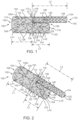
- FIG. 1 is a side plan view of a first modular stent device 100 in accordance with one embodiment.
- FIG. 2 is a perspective view of modular stent device 100 of FIG. 1 in accordance with one embodiment.
- modular stent device 100 sometimes called a prosthesis or aortic arch prosthesis, includes a main body 102, a bypass gate 104 and an artery leg 106, sometimes called a brachiocephalic artery (BCA) leg/limb 106.
- BCA brachiocephalic artery
- main body 102 includes a main body proximal opening 108 at a proximal end 110 of main body 102.
- a distal end 112 of main body 102 is coupled to a proximal end 114 of bypass gate 104 and a proximal end 116 of artery leg 106.
- Bypass gate 104 includes a bypass gate distal opening 118 at a distal end 120 of bypass gate 104.
- Artery leg 106 includes a leg distal opening 122 at a distal end 124 of artery leg 106. Openings 118, 122 are sometime called distal first and second openings 118, 122, respectively.
- the proximal end of a prosthesis such as modular stent device 100 is the end closest to the heart via the path of blood flow whereas the distal end is the end furthest away from the heart during deployment.
- the distal end of the catheter is usually identified to the end that is farthest from the operator/handle while the proximal end of the catheter is the end nearest the operator/handle.
- the distal end of the catheter is the end that is farthest from the operator (the end furthest from the handle) while the distal end of modular stent device 100 is the end nearest the operator (the end nearest the handle), i.e., the distal end of the catheter and the proximal end of modular stent device 100 are the ends furthest from the handle while the proximal end of the catheter and the distal end of modular stent device 100 are the ends nearest the handle.
- the distal end of the catheter and the proximal end of modular stent device 100 are the ends furthest from the handle while the proximal end of the catheter and the distal end of modular stent device 100 are the ends nearest the handle.
- modular stent device 100 and the delivery system descriptions may be consistent or opposite in actual usage.
- Main body 102 includes graft material 126 and one or more circumferential stents 128 coupled to graft material 126.
- Graft material 126 may be any suitable graft material, for example and not limited to, woven polyester, DACRON° material, expanded polytetrafluoroethylene, polyurethane, silicone, electro spun materials, or other suitable materials.
- Circumferential stents 128 may be coupled to graft material 126 using stitching or other means. In the embodiment shown in FIGS. 1 and 2 , circumferential stents 128 are coupled to an outside surface of graft material 126. However, circumferential stents 128 may alternatively be coupled to an inside surface of graft material 126.
- main body 102 may include a greater or smaller number of stents 128, e.g., depending upon the desired length of main body 102 and/or the intended application thereof.
- Circumferential stents 128 may be any stent material or configuration. As shown, circumferential stents 128, e.g., self-expanding members, are preferably made from a shape memory material, such as nickel-titanium alloy (nitinol), and are formed into a zig-zag configuration. The configuration of circumferential stents 128 is merely exemplary, and circumferential stents 128 may have any suitable configuration, including but not limiting to a continuous or non-continuous helical configuration. In another embodiment, circumferential stents 128 are balloon expandable stents.
- a shape memory material such as nickel-titanium alloy (nitinol)
- proximal-most stent 128A extends only to the edge of graft material 126 in a closed-web configuration as shown. However, in another embodiment, proximal-most stent 128A extends proximally past the edge of graft material 126 in an open-web or uncovered configuration.
- main body 102 includes a longitudinal axis LA1.
- a lumen 130 is defined by graft material 126, and generally by main body 102.
- Lumen 130 extends generally parallel to longitudinal axis LA1 and between proximal opening 108 and distal end 112 of main body 102.
- Graft material 126 is cylindrical having a substantially uniform diameter in this embodiment. However, in other embodiments, graft material 126 varies in diameter.
- Bypass gate 104 includes graft material 132 and one or more circumferential stents 134 coupled to graft material 132.
- Graft material 132 may be any suitable graft material, for example and not limited to, woven polyester, DACRON° material, expanded polytetrafluoroethylene, polyurethane, silicone, electro spun materials, or other suitable materials.
- Circumferential stents 134 may be coupled to graft material 132 using stitching or other means. In the embodiment shown in FIGS. 1 and 2 , circumferential stents 134 are coupled to an outside surface of graft material 132. However, circumferential stents 134 may alternatively be coupled to an inside surface of graft material 132.
- bypass gate 104 may include a greater or smaller number of stents 134, e.g., depending upon the desired length of bypass gate 104 and/or the intended application thereof.
- Circumferential stents 134 may be any stent material or configuration. As shown, circumferential stents 110, e.g., self-expanding members, are preferably made from a shape memory material, such as nickel-titanium alloy (nitinol), and are formed into a zig-zag configuration. The configuration of circumferential stents 134 is merely exemplary, and circumferential stents 134 may have any suitable configuration, including but not limiting to a continuous or non-continuous helical configuration. In another embodiment, circumferential stents 134 are balloon expandable stents.
- a shape memory material such as nickel-titanium alloy (nitinol)
- bypass gate 104 includes a longitudinal axis LA2.
- a lumen 136 is defined by graft material 132, and generally by bypass gate 104.
- Lumen 136 extends generally parallel to longitudinal axis LA2 and between proximal end 114 and distal opening 118 of bypass gate 104.
- Graft material 132 is cylindrical having a substantially uniform diameter in this embodiment. However, in other embodiments, graft material 132 varies in diameter.
- Artery leg 106 includes graft material 138 and one or more circumferential stents 140 coupled to graft material 138.
- Graft material 138 may be any suitable graft material, for example and not limited to, woven polyester, DACRON° material, expanded polytetrafluoroethylene, polyurethane, silicone, electro spun materials, or other suitable materials.
- Circumferential stents 140 may be coupled to graft material 138 using stitching or other means. In the embodiment shown in FIGS. 1 and 2 , circumferential stents 140 are coupled to an outside surface of graft material 138. However, circumferential stents 140 may alternatively be coupled to an inside surface of graft material 138.
- artery leg 106 may include a greater or smaller number of stents 140, e.g., depending upon the desired length of artery leg 106 and/or the intended application thereof.
- Circumferential stents 140 may be any stent material or configuration. As shown, circumferential stents 140, e.g., self-expanding members, are preferably made from a shape memory material, such as nickel-titanium alloy (nitinol), and are formed into a zig-zag configuration. The configuration of circumferential stents 140 is merely exemplary, and circumferential stents 140 may have any suitable configuration, including but not limiting to a continuous or non-continuous helical configuration. In another embodiment, circumferential stents 140 are balloon expandable stents.
- a shape memory material such as nickel-titanium alloy (nitinol)
- artery leg 106 includes a longitudinal axis LA3.
- a lumen 142 is defined by graft material 138, and generally by artery leg 106.
- Lumen 142 extends generally parallel to longitudinal axis LA3 and between proximal end 116 and distal opening 122 of artery leg 106.
- Graft material 138 is cylindrical having a substantially uniform diameter in this embodiment. However, in other embodiments, graft material 138 varies in diameter.
- main body 102 is bifurcated at distal end 112 into bypass gate 104 and artery leg 106. More particularly, lumen 130 of main body 102 is bifurcated into lumen 136 of bypass gate 104 and lumen 142 of artery leg 106.
- graft materials 126, 132, 138 may be the same graft material, e.g., may be a single piece of graft material cut and sewn. However, in other embodiments, one or more of graft materials 126, 132, 138 may be different that the others of graft materials 126, 132, 138, e.g., different graft materials are cut and sewn together.
- longitudinal axes LA1, LA2, and LA3 are parallel with one another such that bypass gate 104 and artery leg 106 extend distally from main body 102.
- Main body 102 has a first diameter D1
- bypass gate 104 has a second diameter D2
- artery leg 106 has a third diameter D3.
- first diameter D1 is greater than second diameter D2.
- second diameter D2 is greater than third diameter D3.
- first diameter D1 is greater than second diameter D2 combined with third diameter D3 (D1>D2+D3) such that bypass gate 104 and artery leg 106 are located within an imaginary cylinder defined by graft material 126 of main body 102 extended in the distal direction.
- the parallel design mimics anatomical blood vessel bifurcations to limit flow disruptions.
- first diameter D1 is greater than second diameter D2 combined with third diameter D3 (D1>D2+D3) at distal end 112 and proximal ends 114, 116, sometimes called the transition region.
- main body 102, bypass gate 104 and/or artery leg 106 flare or taper away from the transition region in accordance with another embodiment, so D1>D2+D3 at the transition region but is not necessarily correct in regions away from the transition region. Flaring is indicated by the dashed lines in FIG. 1 .
- the transition region from main body 102 to artery leg 106 and bypass gate 104 does not exceed first diameter D1 of main body 102. This insures artery leg 106 and bypass gate 104 don't crush each other or negatively impact flow in any way. By avoiding having artery leg 106 and bypass gate 104 extend out wider than main body 102, a good seal of stents 128 of main body 102 against the aorta is insured and type I endoleaks are minimized or avoided.
- the transition region between main body 102 and artery leg 106 and bypass gate 104 is fully supported by one or more supporting stents, e.g., stents 128, 134, 140, to prevent kinking in angled anatomy. Absent the supporting stents, modular stent device 100 may be predispose to kinking in type III arches or gothic arches.
- Main body 102 has a first length L1 in a direction parallel to the longitudinal axis LA1
- bypass gate 104 has a second length L2 in a direction parallel to the longitudinal axis LA2
- artery leg 106 has a third length L3 in a direction parallel to the longitudinal axis LA3.
- third length L3 is greater than second length L2 such that distal opening 122 the artery leg 106 is distal to distal opening 118 of bypass gate 104.
- artery leg 106 is longer than bypass gate 104.
- first diameter D1 ranges from 26mm to 54mm. In another embodiment, first diameter D1 is smaller for a second device to treat the left common carotid or left subclavian artery and first diameter D1 is as small as 22mm for transections. In one particular embodiment, first diameter D1 is in the range of 20mm to 60mm.
- second diameter D2 is any one of a number of values to accommodate a minimum diameter of artery leg 106 and the various possible diameters D1 of main body 102.
- second diameter D2 of bypass gate 104 is maximized by subtracting the third diameter D3 of artery leg 106 from first diameter D1 of main body 102.
- the minimum diameter of artery leg 106 is suitably around 10mm to 14mm. Accordingly, when first diameter D1 is 20mm, second diameter D2 of bypass gate 104 is 10mm.
- second diameter D2 is as large as 50mm in another embodiment.
- second diameter D2 is in the approximate range of 10mm to 46mm.
- Third diameter D3 is the diameter for the innominate artery, the left subclavian, and/or the left common carotid in one embodiment.
- the innominate artery ranges in size from approximately 10mm up to 24mm.
- the left subclavian artery size range is closer to 8mm to 14mm and the left common carotid artery is in the 6mm to 10mm range.
- third diameter D3 is suitably in the approximate range of 6mm to 24mm and in one particular embodiment is in the approximate range of 5mm to 22mm.
- landing is targeted in the middle of the ascending aorta.
- the distance between the sinotubular junction STJ and innominate artery ranges in size from 4-8cm so first length L1 is suitably in the range of around 4cm to 8 cm.
- first length L1 can vary.
- first length L1 is in the approximate range of 10mm to 160mm.
- a proximal cuff is used as discussed further below.
- Second length L2 is suitably sufficient for providing adequate overlap in an environment with significant respiratory and cardiac induced motion. It is also suitable to space bypass gate 104 so that bypass gate 104 does not inadvertently open inside of a target branch. In one embodiment, second length L2 is suitably in the approximate range of 10mm to 240mm and in one particular embodiment is in the range of 20mm to 70mm. In one embodiment, the minimum overlap is shortened by providing some mechanism for anchoring of the device.
- Third length L3 is suitably in the approximate range of 30mm to 400mm in one embodiment and is in the range of 20mm to180mm in one particular embodiment.
- artery leg 106 is extended with additional devices.
- main body 102, bypass gate 104 and/or artery leg 106 are non-uniform in diameter.
- main body 102 flares or tapers at proximal end 110.
- bypass gate 104 and/or artery leg 106 flare or taper at distal ends 120, 124, respectively.
- bypass gate 104 and/or artery leg 106 flare or taper at distal ends 120, 124 to enhance sealing.
- Artery leg 106 is configured to exert a higher radial force than the radial force of bypass gate 104.
- radial force includes both a radial force exerted during expansion/deployment as well as a chronic radial force continuously exerted after implantation such that a scaffold has a predetermined compliance or resistance as the surrounding native anatomy, e.g., the aorta, expands and contracts during the cardiac cycle.
- the radial force of bypass gate 104 is configured to be lower than that of artery leg 106 to avoid collapse of artery leg 106 when bypass gate 104 is deployed against and adjacent thereof and thus maintain perfusion of the brachiocephalic artery as discussed further below.
- circumferential stents 140 of artery leg 106 be constructed with relatively thicker and/or shorter segments of material than circumferential stents 134 of bypass gate 104. Shorter and/or thicker circumferential stents 140 have less flexibility but greater radial force to ensure that circumferential stents 134 of bypass gate 104 do not collapse lumen 142 of artery leg 106. Other variations or modification of circumferential stents 134, 140 may be used to achieve relative radial forces in other embodiments.
- Modular stent device 100 further includes radiopaque markers 150, 152, 154.
- radiopaque marker 150 is shaped as a figure 8 marker, i.e., in the shape of the number 8. Radiopaque marker 150 is sewn into graft material 126 in line with artery leg 106. Under fluoroscopy, radiopaque marker 150 is rotated so that it is seen on the edge on the outer curvature of the aortic arch in one embodiment so that artery leg 106 is accurately and reproducibly deployed on the outer curve of the aorta.
- Radiopaque maker 152 is sewn in the transition region where main body 102 meets bypass gate 104 and artery leg 106 to indicate the desired extent of overlap.
- Radiopaque marker 154 e.g., a coil marker, is sewn into bypass gate 104 to aid in cannulation of bypass gate 104.
- FIG. 3 is a cross-sectional view of a vessel assembly 300 including modular stent device 100 of FIGS. 1 and 2 during deployment in accordance with one embodiment.
- the thoracic aorta 302 has numerous arterial branches.
- the arch AA of the aorta 302 has three major branches extending therefrom, all of which usually arise from the convex upper surface of the arch AA.
- the brachiocephalic artery BCA originates anterior to the trachea.
- the brachiocephalic artery BCA divides into two branches, the right subclavian artery RSA (which supplies blood to the right arm) and the right common carotid artery RCC (which supplies blood to the right side of the head and neck).
- the left common carotid artery LCC artery arises from the arch AA of the aorta 302 just to the left of the origin of the brachiocephalic artery BCA.
- the left common carotid artery LCC supplies blood to the left side of the head and neck.
- Aneurysms, dissections, penetrating ulcers, intramural hematomas and/or transections may occur in the aorta arch AA and the peripheral arteries BCA, LCC, LSA.
- thoracic aortic aneurysms include aneurysms present in the ascending thoracic aorta, the aortic arch AA, and one or more of the branch arteries BCA, LCC, LSA that emanate therefrom.
- Thoracic aortic aneurysms also include aneurysms present in the descending thoracic aorta and branch arteries that emanate therefrom. Accordingly, the aorta 302 as illustrated in FIG. 3 has a diseased region similar to any one of those discussed above which will be bypassed and excluded using modular stent device 100 as discussed below.
- a guide wire 304 is introduced via supra aortic access, e.g. through the right subclavian artery RSA, and advanced into the ascending aorta 302.
- a delivery system 306 including modular stent device 100 is introduced via supra aortic access, e.g. through the right subclavian artery RSA, and is advanced into the ascending aorta 302 over guidewire 304.
- Delivery system 306 is positioned at the desired location such that the position of modular stent device 100 is in the ascending aorta near the aortic valve AV.
- delivery system 306 includes a tip capture mechanism 308 and a delivery sheath 310.
- Delivery sheath 310 maintains modular stent device 100 in a collapsed configuration during delivery to the desired location within the aorta 302.
- Tip capture mechanism 308 captures proximal end 110 of main body 102, e.g., proximal circumferential stent 128A, and keeps proximal end 110 in a collapsed configuration until released as discussed further below.
- Tip capture mechanism 308 controls proximal deployment accuracy in a highly mobile environment with large amounts of fluid flow, e.g., in the ascending aorta.
- FIG. 4 is a cross-sectional view of vessel assembly 300 of FIG. 3 at a later stage during deployment of modular stent device 100 in accordance with one embodiment.
- delivery sheath 310 is withdrawn to expose main body 102, bypass gate 104, and the proximal most portion of artery leg 106.
- This deploys main body 102 and bypass gate 104 which self-expand into the aorta 302.
- Bypass gate 104 is opened thus insuring perfusion to distal territories, e.g., including the aorta 302, the left common carotid LCC, and the left subclavian artery LCA.
- Radiopaque marker 150 aids in positioning of modular stent device 100 during deployment.
- bypass gate 104 limits wind socking of modular stent device 100 during deployment. More particularly, the relatively large diameter D2 of bypass gate 104 readily allows blood flow through bypass gate 104 thus minimizing undesirable motion of modular stent device 100 during deployment.
- proximal end 110 of main body 102 remains captured within tip capture mechanism 308 and the distal portion of artery leg 106 remains collapsed and captured within delivery sheath 310.
- Modular stent device 100 is moved, e.g., proximally or distally and/or rotated, if necessary, until positioned at the desired location.
- the closed web tip capture system of tip capture mechanism 308 insures accurate deployment at the sinotubular junction STJ to maximize the proximal seal of modular stent device 100 in the aorta 302.
- FIG. 5 is a cross-sectional view of vessel assembly 300 of FIG. 4 at a later stage during deployment of modular stent device 100 in accordance with one embodiment.
- delivery sheath 310 is completely withdrawn to expose the entirety of artery leg 106.
- This deploys artery leg 106 which expands into the brachiocephalic artery BCA.
- proximal end 110 of main body 102 is released from tip capture mechanism 308 and thus expands into aorta 302.
- this completes deployment of modular stent device 100 is Generally, this completes deployment of modular stent device 100.
- artery leg 106 As artery leg 106 has a greater radial force than bypass gate 104, artery leg 106 remains un-collapsed and opened. Accordingly, blood flow through artery leg 106 and perfusion of the brachiocephalic artery BCA and preservation of blood flow to cerebral territories including the brain is insured. This avoids stroke, or other medical complications from occlusion of the brachiocephalic artery BCA.
- artery leg 106 is released within brachiocephalic artery BCA and accordingly is necessarily located therein. Artery leg 106 is located within brachiocephalic artery BCA regardless of the radial orientation or longitudinal (axial) placement of modular stent device 100 within the aorta 302. By avoiding the requirement of precise radial orientation and longitudinal placement of modular stent device 100, the complexity of the procedure of deploying modular stent device 100 is reduced thus insuring the most possible favorable outcome.
- bypass gate 104 has a sufficiently large diameter D2 such that any collapse of bypass gate 104 is partial and blood flow through bypass gate 104 and the aorta 302 is maintained.
- FIG. 6 is a cross-sectional view of vessel assembly 300 of FIG. 5 at a later stage during deployment of a second modular stent device 100A in accordance with one embodiment.
- second modular stent device 100A is the same or similar to modular stent device 100, the discussion of which is applicable to the second modular stent device 100A.
- second modular stent device 100A is deployed in a reverse, sometimes called mirrored, arrangement as compared to modular stent device 100. More particularly, an artery leg 106A of modular stent device 100A is deployed within the left subclavian artery LSA via supra aortic access through the left subclavian artery LSA.
- a bypass gate 104A of modular stent device 100A is located within aorta 302 and arranged to face and point towards bypass gate 104 of modular stent device 100.
- a main body 102A of modular stent device 100A is located within the descending aorta 302. Modular stent device 100A is deployed in a manner similar to deployment of modular stent device 100 as described in relation to FIGS. 3-5 and only the significant differences are discussed below.
- blood flow enters modular stent device 100A through bypass gate 104A, and exits through main body 102A and artery leg 106A. Accordingly, blood flow through artery leg 106A and perfusion of the left subclavian artery LSA is insured.
- proximal end of a prosthesis such as modular stent device 100A is the end closest to the heart via the path of blood flow whereas the distal end is the end furthest away from the heart during deployment. Accordingly, due to the reverse deployment of modular stent device 100A as compared to modular stent device 100, the naming of certain features is reversed in modular stent device 100A as compared to modular stent device 100.
- proximal opening 108, proximal end 110, distal end 112, proximal end 114, distal opening 118, distal end 120 of modular stent device 100 are called distal opening 108A, distal end 110A, proximal end 112A, distal end 114A, proximal opening 118A, proximal end 120A of modular stent device 100A, respectively.
- FIG. 7 is a cross-sectional view of vessel assembly 300 of FIG. 6 at a final stage during deployment of a tube graft 702 into modular stent devices 100, 100A in accordance with one embodiment.
- tube graft 702 is deployed within and spans bypass gates 104, 104A.
- Tube graft 702 includes graft material 704 and one or more circumferential stents 706.
- Graft material 704 includes any one of the graft materials as discussed above in relation to graft materials 126, 132, 138.
- circumferential stents 706 are similar to or identical to any one of circumferential stents 128, 134, 140 as discussed above.
- tube graft 702 Upon completion of deployment of tube graft 702, blood flows from bypass gate 104 through tube graft 702 and to bypass gate 104A. In this manner, any overlapped diseased regions of the aorta 302 are excluded.
- tube graft 702 overlaps, excludes and thus occludes the left common carotid artery LCC.
- a bypass 708 provides perfusion to the left common carotid artery LCC.
- bypass 708 provides perfusion of the left common carotid artery LCC from the left subclavian artery LSA.
- Bypass 708 is surgically inserted during the same procedure as deployment of modular stent device 100A and tube graft 702.
- bypass 708 is surgically inserted prior to deployment of modular stent device 100A and tube graft 702, e.g., to simplify the procedure.
- a proximal cuff 712 is coupled to main body 102 of modular stent device 100 and extend proximately therefrom.
- proximal cuff 712 is deployed in the event that proximal end 110 of main body 102 is deployed distally from the aortic valve AV to extend between the desired deployment location and proximal end 110 of main body 102.
- Proximal cuff 712 is optional and in one embodiment is not deployed or used.
- Proximal cuff 712 includes graft material 714 and one or more circumferential stents 716.
- Graft material 714 includes any one of the graft materials as discussed above in relation to graft materials 126, 132, 138.
- circumferential stents 716 are similar to or identical to anyone of circumferential stents 128, 134, 140 as discussed above.
- FIG. 8 is a cross-sectional view of vessel assembly 300 of FIG. 5 at a later stage during deployment of second modular stent device 100A in accordance with another embodiment.
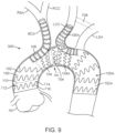
- FIG. 9 is a cross-sectional view of vessel assembly 300 of FIG. 8 at a final stage during deployment of tube graft 702 into modular stent devices 100, 100A in accordance with one embodiment.
- FIGS. 8 and 9 are similar to FIGS. 6 and 7 and only the significant differences are discussed below.
- artery leg 106A of modular stent device 100A is deployed within the left common carotid artery LCC via supra aortic access through the left common carotid artery LCC. Accordingly, blood flow through artery leg 106A and perfusion of the left common carotid artery LCC is insured.
- tube graft 702 and/or modular stent device 100A overlaps, excludes and thus occludes the left subclavian artery LSA.
- bypass 708 provides perfusion to the left subclavian artery LSA.
- bypass 708 provides perfusion of the left subclavian artery LSA from the left common carotid artery LCC.
- FIG. 10 is a cross-sectional view of vessel assembly 300 of FIG. 5 at a later stage during deployment of second modular stent device 100B in accordance with another embodiment.
- Second modular stent device 100B is the same or similar to modular stent device 100, the discussion of which is applicable to the second modular stent device 100B.
- an artery leg 106B of modular stent device 100B is deployed within the left subclavian artery LSA via supra aortic access through the left subclavian artery LSA.
- a bypass gate 104B of modular stent device 100B is located within aorta 302 and arranged to point away and distally from modular stent device 100.
- a main body 102B of modular stent device 100B is located within bypass gate 104 of modular stent device 100.
- blood flow enters modular stent device 100B through main gate 102B, and exits through bypass gate 104B and artery leg 106B. Accordingly, blood flow through artery leg 106B and perfusion of the left subclavian artery LSA is insured. In this manner, any overlapped diseased regions of the aorta 302 are excluded.
- modular stent device 100B overlaps, excludes and thus occludes the left common carotid artery LCC.
- bypass 708 provides perfusion to the left common carotid artery LCC.
- bypass 708 provides perfusion of the left common carotid artery LCC from the left subclavian artery LSA.
- FIG. 11 is a cross-sectional view of vessel assembly 300 of FIG. 10 at a final stage during deployment of a tube graft 1102 into modular stent device 100B in accordance with one embodiment.
- tube graft 1102 is deployed into bypass gate 104B and into aorta 302 and is attached thereto.
- Tube graft 1102 includes graft material 1104 and one or more circumferential stents 1106.
- Graft material 1104 includes any one of the graft materials as discussed above in relation to graft materials 126, 132, 138.
- circumferential stents 1106 are similar to or identical to anyone of circumferential stents 128, 134, 140 as discussed above.
- proximal cuff 712 is coupled to main body 102 of modular stent device 100 and extend proximately therefrom.
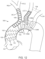
- FIG. 12 is a cross-sectional view of vessel assembly 300 of FIG. 5 at a later stage during deployment of second modular stent device 100B in accordance with another embodiment.
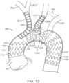
- FIG. 13 is a cross-sectional view of vessel assembly 300 of FIG. 12 at a final stage during deployment of tube graft 1102 into modular stent device 100B in accordance with one embodiment.
- FIGS. 12 and 13 are similar to FIGS. 10 and 11 and only the significant differences are discussed below.
- artery leg 106B of modular stent device 100B is deployed within the left common carotid artery LCC via supra aortic access through the left common carotid artery LCC. Accordingly, blood flow through artery leg 106B and perfusion of the left common carotid artery LCC is insured.
- tube graft 1102 and/or modular stent device 100B overlaps, excludes and thus occludes the left subclavian artery LSA.
- bypass 708 provides perfusion to the left subclavian artery LSA.
- bypass 708 provides perfusion of the left subclavian artery LSA from the left common carotid artery LCC.
- FIG. 14 is a cross-sectional view of vessel assembly 300 of FIG. 5 at a later stage during deployment of a distal aortic stent-graft prosthesis 1400, sometimes called a second modular stent device 1400, in accordance with another embodiment.
- Distal aortic stent-graft prosthesis 1400 includes a main body 1402 and a coupling 1404 extending radially from main body 1402.
- Main body 1402 is generally cylindrically shaped but can vary in diameter in other embodiments.
- a proximal end 1406 of main body 1402 of distal aortic stent-graft prosthesis 1400 is deployed within bypass gate 104 of modular stent device 100 via femoral access.
- Main body 1402 extends distally from bypass gate 104 and a distal end 1408 of main body 1402 is deployed within the descending aorta 302.
- main body 1402 defines a lumen extending therethrough.
- Main body 1402 is deployed such that coupling 1404 is aligned with the left subclavian artery LSA.
- Coupling 1404 corresponds with an opening in the main body 1402.
- Coupling 1404 is generally frustoconically shaped and includes a base 1410 and a top 1412. A circumference of base 1410 is greater than a circumference of top 1412.
- Coupling 1404 defines a lumen in fluid communication with the lumen of main body 1402.
- bypass gate 104 of modular stent device 100 enters proximal end 1406 of main body 1402. Blood flows through the lumen of main body 1402 and exits distal end 1408 and into the aorta 302.
- blood flow from the lumen of main body 1402 flows through coupling 1404 and into the left subclavian artery LSA. More particularly, blood flows enter into base 1410 of coupling 1404, through the lumen of coupling 1404, and exits top 1412 of coupling 1404 into the left subclavian artery LSA.
- Main body 1402 includes graft material 1414 and one or more circumferential stents 1416.
- Graft material 1414 includes any one of the graft materials as discussed above in relation to graft materials 126, 132, 138.
- circumferential stents 1416 are similar to or identical to anyone of circumferential stents 128, 134, 140 as discussed above.
- Coupling 1404 includes graft material 1418 and one or more circumferential stents 1420.
- Graft material 1418 includes any one of the graft materials as discussed above in relation to graft materials 126, 132, 138.
- circumferential stents 1416 are similar to or identical to anyone of circumferential stents 128, 134, 140 as discussed above.
- FIG. 15 is a cross-sectional view of vessel assembly 300 of FIG. 14 at a later stage during deployment of a bridging stent graft 1502 in accordance with one embodiment.
- bridging stent graft 1502 is deployed within coupling 1404 and within the left subclavian artery LSA. More particularly, bridging stent graft 1502 is anchored within coupling 1404 and the left subclavian artery LSA. Bridging stent graft 1502 is deployed via supra aortic access through the left subclavian artery LSA or alternatively through femoral access.
- Bridging stent graft 1502 includes graft material 1504 and one or more circumferential stents 1506.
- Graft material 1504 includes any one of the graft materials as discussed above in relation to graft materials 126, 132, 138.
- circumferential stents 1506 are similar to or identical to anyone of circumferential stents 128, 134, 140 as discussed above.
- bridging stent graft 1502 Upon deployment of bridging stent graft 1502, blood flow into coupling 1404 is bridged and passed into the left subclavian artery LSA through bridging stent graft 1502.
- bypass 708 provides perfusion to the left common carotid artery LCC.
- bypass 708 provides perfusion of the left common carotid artery LCC from the left subclavian artery LSA.
- proximal cuff 712 can be coupled to main body 102 of modular stent device 100 and extend proximately therefrom.
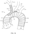
- FIG. 16 is a cross-sectional view of vessel assembly 300 of FIG. 5 at a later stage during deployment of a distal aortic stent-graft prosthesis 1400A, sometimes called a second modular stent device 1400A, in accordance with another embodiment.
- FIG. 17 is a cross-sectional view of vessel assembly 300 of FIG. 16 at a later stage during deployment of bridging stent graft 1502 in accordance with one embodiment.
- FIGS. 16 and 17 are similar to FIGS. 14 and 15 and only the significant differences are discussed below.
- the positioning of coupling 1404 upon main body 1402 in aortic stent-graft prosthesis 1400A is different (more proximal) than the position of coupling 1404 upon main body 1402 in aortic stent-graft prosthesis 1400 of FIGS. 14 and 15 .
- Main body 1402 is deployed such that coupling 1404 is aligned with the left common carotid artery LCC in accordance with this embodiment.
- blood flow from the lumen of main body 1402 flows through coupling 1404 and into the left common carotid artery LCC. More particularly, blood flows enter into base 1410 of coupling 1404, through the lumen of coupling 1404, and exits top 1412 of coupling 1404 into the left common carotid artery LCC.
- bridging stent graft 1502 is deployed within coupling 1404 and within the left common carotid artery LCC. More particularly, bridging stent graft 1502 is anchored within coupling 1404 and the left common carotid artery LCC. Bridging stent graft 1502 is deployed via supra aortic access through the left common carotid artery LCC or alternatively through femoral access. Upon deployment of bridging stent graft 1502, blood flow into coupling 1404 is bridged and passed into the left common carotid artery LCC through bridging stent graft 1502.
- bypass 708 provides perfusion to the left subclavian artery LSA.
- bypass 708 provides perfusion of the left subclavian artery LSA from the left common carotid artery LCC.
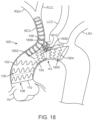
- FIG. 18 is a cross-sectional view of vessel assembly 300 of FIG. 5 at a later stage during deployment of double gate bifurcated device 1800, sometimes called a second modular stent device, in accordance with another embodiment.
- double gate bifurcated device 1800 includes a main body 1802, a bypass gate 1804, a first arterial gate 1806, and a second arterial gate 1808.
- main body 1802 is deployed within bypass gate 104 of modular stent device 100.
- double gate bifurcated device 1800 is deployed via supra-aortic access, e.g., from the left subclavian artery LSA (left arm access).
- Double gate bifurcated device 1800 includes graft material(s) and stent(s) such as those discussed above.
- FIG. 19 is a cross-sectional view of vessel assembly 300 of FIG. 18 at a later stage during deployment of bridging stent grafts 1902, 1904 in accordance with one embodiment.
- bridging stent grafts 1902, 1904 are deployed within first arterial gate 1806 and second arterial gate 1808 and within the left common carotid artery LCC and the left subclavian artery LSA, respectively. More particularly, bridging stent graft 1902 is anchored within first arterial gate 1806 and the left common carotid artery LCC. Bridging stent graft 1904 is anchored within second arterial gate 1808 and the left subclavian artery LSA. Bridging stent grafts 1902, 1904 are deployed via supra aortic access through the left common carotid artery LCC and the left subclavian artery LSA, respectively.
- Bridging stent graft grafts 1902, 1904 includes graft materials 1906, 1908 and one or more circumferential stents 1910, 1912, respectively.
- Graft materials 1906 and/or 1908 include any one of the graft materials as discussed above in relation to graft materials 126, 132, 138.
- circumferential stents 1910 and/or 1912 are similar to or identical to anyone of circumferential stents 128, 134, 140 as discussed above.
- first arterial gate 1806 and second arterial gate 1808 Upon deployment of bridging stent graft grafts 1902, 1904, blood flow into first arterial gate 1806 and second arterial gate 1808 is bridged and passed into the left common carotid artery LCC and the left subclavian artery LSA through bridging stent grafts 1902, 1904, respectively.
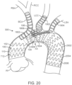
- FIG. 20 is a cross-sectional view of vessel assembly 300 of FIG. 19 at a final stage during deployment of a tube graft 2002 into double gate bifurcated device 1800 in accordance with one embodiment.
- tube graft 2002 is deployed into bypass gate 1804 and into aorta 302 and is attached thereto.
- Tube graft 2002 includes graft material 2004 and one or more circumferential stents 2006.
- Graft material 2004 includes any one of the graft materials as discussed above in relation to graft materials 126, 132, 138.
- circumferential stents 2006 are similar to or identical to anyone of circumferential stents 128, 134, 140 as discussed above.
- proximal cuff 712 is coupled to main body 102 of modular stent device 100 and extend proximately therefrom.
- FIG. 21 is a cross-sectional view of vessel assembly 300 of FIG. 5 at a later stage during deployment of a double gate bifurcated device 1800A, sometimes called a second modular stent device, in accordance with another embodiment.
- FIG. 22 is a cross-sectional view of vessel assembly 300 of FIG. 21 at a later stage during deployment of bridging stent grafts 1902, 1904 in accordance with one embodiment.
- FIGS. 21 and 22 are similar to FIGS. 19 and 20 and only the significant differences are discussed below.
- double gate bifurcated device 1800A includes main body 1802, a bypass gate 1804A, first arterial gate 1806, and second arterial gate 1808.
- Bypass gate 1804A of double gate bifurcated device 1800A is longer than bypass gate 1804 of double gate bifurcated device 1800 eliminating the need of tube graft 2002 (see FIG. 20 ).
- main body 1802 is deployed within bypass gate 104 of modular stent device 100.
- double gate bifurcated device 1800 is deployed via femoral access.
- Bypass gate 1804A is deployed within the aorta 302.
Landscapes
- Health & Medical Sciences (AREA)
- Engineering & Computer Science (AREA)
- Biomedical Technology (AREA)
- Cardiology (AREA)
- Oral & Maxillofacial Surgery (AREA)
- Transplantation (AREA)
- Heart & Thoracic Surgery (AREA)
- Vascular Medicine (AREA)
- Life Sciences & Earth Sciences (AREA)
- Animal Behavior & Ethology (AREA)
- General Health & Medical Sciences (AREA)
- Public Health (AREA)
- Veterinary Medicine (AREA)
- Gastroenterology & Hepatology (AREA)
- Pulmonology (AREA)
- Prostheses (AREA)
Abstract
Description
- The present technology is generally related to an intra-vascular device and method. More particularly, the present application relates to a device for treatment of intra-vascular diseases.
- Aneurysms, dissections, penetrating ulcers, intramural hematomas and/or transections may occur in blood vessels, and most typically occur in the aorta and peripheral arteries. The diseased region of the aorta may extend into areas having vessel bifurcations or segments of the aorta from which smaller "branch" arteries extend.
- The diseased region of the aorta can be bypassed by use of a stent-graft placed inside the vessel spanning the diseased portion of the aorta, to seal off the diseased portion from further exposure to blood flowing through the aorta.
- The use of stent-grafts to internally bypass the diseased portion of the aorta is not without challenges. In particular, care must be taken so that critical branch arteries are not covered or occluded by the stent-graft yet the stent-graft must seal against the aorta wall and provide a flow conduit for blood to flow past the diseased portion.
- The techniques of this disclosure generally relate to a modular stent device configured to be deployed via supra aortic access through the brachiocephalic artery. The modular stent device is a base or anchor component to which additional modular stent devices can be attached to exclude diseased areas of the aorta while at the same time allowing perfusion of the left common carotid artery and the left subclavian artery.
- In one aspect, the present disclosure provides an assembly including a first modular stent device. The first modular stent device includes a main body, a bypass gate extending distally from a distal end of the main body, and an artery leg extending distally from the distal end of the main body. The artery leg has a greater radial force than a radial force of the bypass gate. The main body has a first longitudinal axis, the bypass gate has a second longitudinal axis, and the artery leg has a third longitudinal axis, the first, second, and third longitudinal axes are parallel with one another when the first modular stent device is in a relaxed configuration. A second modular stent device is configured to be coupled inside the bypass gate.
- In another aspect, the present disclosure provides an assembly including the first modular stent device and a stent-graft prosthesis configured to be coupled inside the bypass gate. In one embodiment, the stent-graft prosthesis includes a main body and a coupling extending radially from the main body of the stent-graft prosthesis.
- In yet another aspect, the present disclosure provides an assembly including the first modular stent device and a double gate bifurcated device configured to be coupled inside the bypass gate.
- The details of one or more aspects of the disclosure are set forth in the accompanying drawings and the description below. Other features, objects, and advantages of the techniques described in this disclosure will be apparent from the description and drawings, and from the claims.
-
-
FIG. 1 is a side plan view of a modular stent device in accordance with one embodiment. -
FIG. 2 is a perspective view of the modular stent device ofFIG. 1 in accordance with one embodiment. -
FIG. 3 is a cross-sectional view of a vessel assembly including the modular stent device ofFIGS. 1 and 2 during deployment in accordance with one embodiment. -
FIG. 4 is a cross-sectional view of the vessel assembly ofFIG. 3 at a later stage during deployment of the modular stent device in accordance with one embodiment. -
FIG. 5 is a cross-sectional view of the vessel assembly ofFIG. 4 at a later stage during deployment of the modular stent device in accordance with one embodiment. -
FIG. 6 is a cross-sectional view of the vessel assembly ofFIG. 5 at a later stage during deployment of a second modular stent device in accordance with one embodiment. -
FIG. 7 is a cross-sectional view of the vessel assembly ofFIG. 6 at a final stage during deployment of a tube graft into the modular stent devices in accordance with one embodiment. -
FIG. 8 is a cross-sectional view of the vessel assembly ofFIG. 5 at a later stage during deployment of a second modular stent device in accordance with another embodiment. -
FIG. 9 is a cross-sectional view of the vessel assembly ofFIG. 8 at a final stage during deployment of a tube graft into the modular stent devices in accordance with one embodiment. -
FIG. 10 is a cross-sectional view of the vessel assembly ofFIG. 5 at a later stage during deployment of a second modular stent device in accordance with another embodiment. -
FIG. 11 is a cross-sectional view of the vessel assembly ofFIG. 10 at a final stage during deployment of a tube graft into the second modular stent device in accordance with one embodiment. -
FIG. 12 is a cross-sectional view of the vessel assembly ofFIG. 5 at a later stage during deployment of a second modular stent device in accordance with another embodiment. -
FIG. 13 is a cross-sectional view of the vessel assembly ofFIG. 12 at a final stage during deployment of a tube graft into the second modular stent device in accordance with one embodiment. -
FIG. 14 is a cross-sectional view of the vessel assembly ofFIG. 5 at a later stage during deployment of a distal aortic stent-graft prosthesis in accordance with another embodiment. -
FIG. 15 is a cross-sectional view of the vessel assembly ofFIG. 14 at a later stage during deployment of a bridging stent graft in accordance with one embodiment. -
FIG. 16 is a cross-sectional view of the vessel assembly ofFIG. 5 at a later stage during deployment of a distal aortic stent-graft prosthesis in accordance with another embodiment. -
FIG. 17 is a cross-sectional view of the vessel assembly ofFIG. 16 at a later stage during deployment of a bridging stent graft in accordance with one embodiment. -
FIG. 18 is a cross-sectional view of the vessel assembly ofFIG. 5 at a later stage during deployment of a double gate bifurcated device in accordance with another embodiment. -
FIG. 19 is a cross-sectional view of the vessel assembly ofFIG. 18 at a later stage during deployment of bridging stent grafts in accordance with one embodiment. -
FIG. 20 is a cross-sectional view of the vessel assembly ofFIG. 19 at a final stage during deployment of a tube graft into the double gate bifurcated device in accordance with one embodiment. -
FIG. 21 is a cross-sectional view of the vessel assembly ofFIG. 5 at a later stage during deployment of a double gate bifurcated device in accordance with another embodiment. -
FIG. 22 is a cross-sectional view of the vessel assembly ofFIG. 21 at a later stage during deployment of bridging stent grafts in accordance with one embodiment. - As an overview and in accordance with one embodiment, referring to
FIG. 5 , amodular stent device 100 is deployed via supra aortic access through the brachiocephalic artery BCA.Modular stent device 100 is a base or anchor component to which additional modular stent devices can be attached to exclude diseased areas of theaorta 302 while at the same time allowing perfusion of the left common carotid artery LCC and the left subclavian artery LCA. - Now in more detail,
FIG. 1 is a side plan view of a firstmodular stent device 100 in accordance with one embodiment.FIG. 2 is a perspective view ofmodular stent device 100 ofFIG. 1 in accordance with one embodiment. - Referring now to
FIGS. 1 and 2 together,modular stent device 100, sometimes called a prosthesis or aortic arch prosthesis, includes amain body 102, abypass gate 104 and anartery leg 106, sometimes called a brachiocephalic artery (BCA) leg/limb 106. - In accordance with this embodiment,
main body 102 includes a main bodyproximal opening 108 at aproximal end 110 ofmain body 102. Adistal end 112 ofmain body 102 is coupled to aproximal end 114 ofbypass gate 104 and aproximal end 116 ofartery leg 106. - Bypass
gate 104 includes a bypass gate distal opening 118 at adistal end 120 ofbypass gate 104.Artery leg 106 includes a leg distal opening 122 at adistal end 124 ofartery leg 106.Openings second openings - As used herein, the proximal end of a prosthesis such as
modular stent device 100 is the end closest to the heart via the path of blood flow whereas the distal end is the end furthest away from the heart during deployment. In contrast and of note, the distal end of the catheter is usually identified to the end that is farthest from the operator/handle while the proximal end of the catheter is the end nearest the operator/handle. - For purposes of clarity of discussion, as used herein, the distal end of the catheter is the end that is farthest from the operator (the end furthest from the handle) while the distal end of
modular stent device 100 is the end nearest the operator (the end nearest the handle), i.e., the distal end of the catheter and the proximal end ofmodular stent device 100 are the ends furthest from the handle while the proximal end of the catheter and the distal end ofmodular stent device 100 are the ends nearest the handle. However, those of skill in the art will understand that depending upon the access location,modular stent device 100 and the delivery system descriptions may be consistent or opposite in actual usage. -
Main body 102 includesgraft material 126 and one or morecircumferential stents 128 coupled tograft material 126.Graft material 126 may be any suitable graft material, for example and not limited to, woven polyester, DACRON° material, expanded polytetrafluoroethylene, polyurethane, silicone, electro spun materials, or other suitable materials. -
Circumferential stents 128 may be coupled tograft material 126 using stitching or other means. In the embodiment shown inFIGS. 1 and 2 ,circumferential stents 128 are coupled to an outside surface ofgraft material 126. However,circumferential stents 128 may alternatively be coupled to an inside surface ofgraft material 126. - Although shown with a particular number of
circumferential stents 128, in light of this disclosure, those of skill in the art will understand thatmain body 102 may include a greater or smaller number ofstents 128, e.g., depending upon the desired length ofmain body 102 and/or the intended application thereof. -
Circumferential stents 128 may be any stent material or configuration. As shown,circumferential stents 128, e.g., self-expanding members, are preferably made from a shape memory material, such as nickel-titanium alloy (nitinol), and are formed into a zig-zag configuration. The configuration ofcircumferential stents 128 is merely exemplary, andcircumferential stents 128 may have any suitable configuration, including but not limiting to a continuous or non-continuous helical configuration. In another embodiment,circumferential stents 128 are balloon expandable stents. - The
circumferential stent 128A of thecircumferential stents 128 which is disposed atproximal end 110 is referred to herein as theproximal-most stent 128A. In the embodiment ofFIGS. 1 and 2 ,proximal-most stent 128A extends only to the edge ofgraft material 126 in a closed-web configuration as shown. However, in another embodiment,proximal-most stent 128A extends proximally past the edge ofgraft material 126 in an open-web or uncovered configuration. - Further,
main body 102 includes a longitudinal axis LA1. Alumen 130 is defined bygraft material 126, and generally bymain body 102.Lumen 130 extends generally parallel to longitudinal axis LA1 and betweenproximal opening 108 anddistal end 112 ofmain body 102.Graft material 126 is cylindrical having a substantially uniform diameter in this embodiment. However, in other embodiments,graft material 126 varies in diameter. -
Bypass gate 104 includesgraft material 132 and one or morecircumferential stents 134 coupled tograft material 132.Graft material 132 may be any suitable graft material, for example and not limited to, woven polyester, DACRON° material, expanded polytetrafluoroethylene, polyurethane, silicone, electro spun materials, or other suitable materials. -
Circumferential stents 134 may be coupled tograft material 132 using stitching or other means. In the embodiment shown inFIGS. 1 and 2 ,circumferential stents 134 are coupled to an outside surface ofgraft material 132. However,circumferential stents 134 may alternatively be coupled to an inside surface ofgraft material 132. - Although shown with a particular number of
circumferential stents 134, in light of this disclosure, those of skill in the art will understand thatbypass gate 104 may include a greater or smaller number ofstents 134, e.g., depending upon the desired length ofbypass gate 104 and/or the intended application thereof. -
Circumferential stents 134 may be any stent material or configuration. As shown,circumferential stents 110, e.g., self-expanding members, are preferably made from a shape memory material, such as nickel-titanium alloy (nitinol), and are formed into a zig-zag configuration. The configuration ofcircumferential stents 134 is merely exemplary, andcircumferential stents 134 may have any suitable configuration, including but not limiting to a continuous or non-continuous helical configuration. In another embodiment,circumferential stents 134 are balloon expandable stents. - Further,
bypass gate 104 includes a longitudinal axis LA2. Alumen 136 is defined bygraft material 132, and generally bybypass gate 104.Lumen 136 extends generally parallel to longitudinal axis LA2 and betweenproximal end 114 anddistal opening 118 ofbypass gate 104.Graft material 132 is cylindrical having a substantially uniform diameter in this embodiment. However, in other embodiments,graft material 132 varies in diameter. -
Artery leg 106 includesgraft material 138 and one or morecircumferential stents 140 coupled tograft material 138.Graft material 138 may be any suitable graft material, for example and not limited to, woven polyester, DACRON° material, expanded polytetrafluoroethylene, polyurethane, silicone, electro spun materials, or other suitable materials. -
Circumferential stents 140 may be coupled tograft material 138 using stitching or other means. In the embodiment shown inFIGS. 1 and 2 ,circumferential stents 140 are coupled to an outside surface ofgraft material 138. However,circumferential stents 140 may alternatively be coupled to an inside surface ofgraft material 138. - Although shown with a particular number of
circumferential stents 140, in light of this disclosure, those of skill in the art will understand thatartery leg 106 may include a greater or smaller number ofstents 140, e.g., depending upon the desired length ofartery leg 106 and/or the intended application thereof. -
Circumferential stents 140 may be any stent material or configuration. As shown,circumferential stents 140, e.g., self-expanding members, are preferably made from a shape memory material, such as nickel-titanium alloy (nitinol), and are formed into a zig-zag configuration. The configuration ofcircumferential stents 140 is merely exemplary, andcircumferential stents 140 may have any suitable configuration, including but not limiting to a continuous or non-continuous helical configuration. In another embodiment,circumferential stents 140 are balloon expandable stents. - Further,
artery leg 106 includes a longitudinal axis LA3. Alumen 142 is defined bygraft material 138, and generally byartery leg 106.Lumen 142 extends generally parallel to longitudinal axis LA3 and betweenproximal end 116 anddistal opening 122 ofartery leg 106.Graft material 138 is cylindrical having a substantially uniform diameter in this embodiment. However, in other embodiments,graft material 138 varies in diameter. - Generally,
main body 102 is bifurcated atdistal end 112 intobypass gate 104 andartery leg 106. More particularly,lumen 130 ofmain body 102 is bifurcated intolumen 136 ofbypass gate 104 andlumen 142 ofartery leg 106. - In one embodiment,
graft materials graft materials graft materials modular stent device 100 as illustrated inFIGS. 1 and 2 , longitudinal axes LA1, LA2, and LA3 are parallel with one another such thatbypass gate 104 andartery leg 106 extend distally frommain body 102. -
Main body 102 has a first diameter D1,bypass gate 104 has a second diameter D2, andartery leg 106 has a third diameter D3. In accordance with this embodiment, first diameter D1 is greater than second diameter D2. Further, second diameter D2 is greater than third diameter D3. In accordance with this embodiment, first diameter D1 is greater than second diameter D2 combined with third diameter D3 (D1>D2+D3) such thatbypass gate 104 andartery leg 106 are located within an imaginary cylinder defined bygraft material 126 ofmain body 102 extended in the distal direction. The parallel design mimics anatomical blood vessel bifurcations to limit flow disruptions. - In one embodiment, first diameter D1 is greater than second diameter D2 combined with third diameter D3 (D1>D2+D3) at
distal end 112 and proximal ends 114, 116, sometimes called the transition region. However,main body 102,bypass gate 104 and/orartery leg 106, flare or taper away from the transition region in accordance with another embodiment, so D1>D2+D3 at the transition region but is not necessarily correct in regions away from the transition region. Flaring is indicated by the dashed lines inFIG. 1 . - Stated another way, the transition region from
main body 102 toartery leg 106 andbypass gate 104 does not exceed first diameter D1 ofmain body 102. This insuresartery leg 106 andbypass gate 104 don't crush each other or negatively impact flow in any way. By avoiding havingartery leg 106 andbypass gate 104 extend out wider thanmain body 102, a good seal ofstents 128 ofmain body 102 against the aorta is insured and type I endoleaks are minimized or avoided. - In accordance with one embodiment, the transition region between
main body 102 andartery leg 106 andbypass gate 104 is fully supported by one or more supporting stents, e.g.,stents modular stent device 100 may be predispose to kinking in type III arches or gothic arches. -
Main body 102 has a first length L1 in a direction parallel to the longitudinal axis LA1,bypass gate 104 has a second length L2 in a direction parallel to the longitudinal axis LA2, andartery leg 106 has a third length L3 in a direction parallel to the longitudinal axis LA3. In accordance with this embodiment, third length L3 is greater than second length L2 such thatdistal opening 122 theartery leg 106 is distal todistal opening 118 ofbypass gate 104. Generally,artery leg 106 is longer thanbypass gate 104. - In one embodiment, first diameter D1 ranges from 26mm to 54mm. In another embodiment, first diameter D1 is smaller for a second device to treat the left common carotid or left subclavian artery and first diameter D1 is as small as 22mm for transections. In one particular embodiment, first diameter D1 is in the range of 20mm to 60mm.
- In one embodiment, second diameter D2 is any one of a number of values to accommodate a minimum diameter of
artery leg 106 and the various possible diameters D1 ofmain body 102. In one embodiment, second diameter D2 ofbypass gate 104 is maximized by subtracting the third diameter D3 ofartery leg 106 from first diameter D1 ofmain body 102. For the brachiocephalic artery, also known as the innominate artery, the minimum diameter ofartery leg 106 is suitably around 10mm to 14mm. Accordingly, when first diameter D1 is 20mm, second diameter D2 ofbypass gate 104 is 10mm. However, second diameter D2 is as large as 50mm in another embodiment. Suitably, second diameter D2 is in the approximate range of 10mm to 46mm. - Third diameter D3 is the diameter for the innominate artery, the left subclavian, and/or the left common carotid in one embodiment. The innominate artery ranges in size from approximately 10mm up to 24mm. The left subclavian artery size range is closer to 8mm to 14mm and the left common carotid artery is in the 6mm to 10mm range. Accordingly, third diameter D3 is suitably in the approximate range of 6mm to 24mm and in one particular embodiment is in the approximate range of 5mm to 22mm.
- In one embodiment, landing is targeted in the middle of the ascending aorta. The distance between the sinotubular junction STJ and innominate artery ranges in size from 4-8cm so first length L1 is suitably in the range of around 4cm to 8 cm. However, to extend coverage all the way to the sinotubular junction STJ, in one embodiment, first length L1 can vary. Suitably, first length L1 is in the approximate range of 10mm to 160mm. Alternatively, a proximal cuff is used as discussed further below.
- Second length L2 is suitably sufficient for providing adequate overlap in an environment with significant respiratory and cardiac induced motion. It is also suitable to
space bypass gate 104 so thatbypass gate 104 does not inadvertently open inside of a target branch. In one embodiment, second length L2 is suitably in the approximate range of 10mm to 240mm and in one particular embodiment is in the range of 20mm to 70mm. In one embodiment, the minimum overlap is shortened by providing some mechanism for anchoring of the device. - Third length L3 is suitably in the approximate range of 30mm to 400mm in one embodiment and is in the range of 20mm to180mm in one particular embodiment. In one embodiment,
artery leg 106 is extended with additional devices. - Although fixed diameters D1, D2, and D3 are illustrated and discussed, in one embodiment,
main body 102,bypass gate 104 and/orartery leg 106 are non-uniform in diameter. For example,main body 102 flares or tapers atproximal end 110. Similarly,bypass gate 104 and/orartery leg 106 flare or taper atdistal ends bypass gate 104 and/orartery leg 106 flare or taper atdistal ends -
Artery leg 106 is configured to exert a higher radial force than the radial force ofbypass gate 104. As used herein, "radial force" includes both a radial force exerted during expansion/deployment as well as a chronic radial force continuously exerted after implantation such that a scaffold has a predetermined compliance or resistance as the surrounding native anatomy, e.g., the aorta, expands and contracts during the cardiac cycle. The radial force ofbypass gate 104 is configured to be lower than that ofartery leg 106 to avoid collapse ofartery leg 106 whenbypass gate 104 is deployed against and adjacent thereof and thus maintain perfusion of the brachiocephalic artery as discussed further below. - To configure
bypass gate 104 andartery leg 106 with differing relative radial forces,circumferential stents 140 ofartery leg 106 be constructed with relatively thicker and/or shorter segments of material thancircumferential stents 134 ofbypass gate 104. Shorter and/or thickercircumferential stents 140 have less flexibility but greater radial force to ensure thatcircumferential stents 134 ofbypass gate 104 do not collapse lumen 142 ofartery leg 106. Other variations or modification ofcircumferential stents -
Modular stent device 100 further includesradiopaque markers radiopaque marker 150 is shaped as afigure 8 marker, i.e., in the shape of the number 8.Radiopaque marker 150 is sewn intograft material 126 in line withartery leg 106. Under fluoroscopy,radiopaque marker 150 is rotated so that it is seen on the edge on the outer curvature of the aortic arch in one embodiment so thatartery leg 106 is accurately and reproducibly deployed on the outer curve of the aorta. -
Radiopaque maker 152 is sewn in the transition region wheremain body 102 meetsbypass gate 104 andartery leg 106 to indicate the desired extent of overlap.Radiopaque marker 154, e.g., a coil marker, is sewn intobypass gate 104 to aid in cannulation ofbypass gate 104. -
FIG. 3 is a cross-sectional view of avessel assembly 300 includingmodular stent device 100 ofFIGS. 1 and 2 during deployment in accordance with one embodiment. Referring toFIGS. 1, 2 and3 together, thethoracic aorta 302 has numerous arterial branches. The arch AA of theaorta 302 has three major branches extending therefrom, all of which usually arise from the convex upper surface of the arch AA. The brachiocephalic artery BCA originates anterior to the trachea. The brachiocephalic artery BCA divides into two branches, the right subclavian artery RSA (which supplies blood to the right arm) and the right common carotid artery RCC (which supplies blood to the right side of the head and neck). The left common carotid artery LCC artery arises from the arch AA of theaorta 302 just to the left of the origin of the brachiocephalic artery BCA. The left common carotid artery LCC supplies blood to the left side of the head and neck. The third branch arising from the aortic arch AA, the left subclavian artery LSA, originates behind and just to the left of the origin of the left common carotid artery LCC and supplies blood to the left arm. - However, a significant proportion of the population has only two great branch vessels coming off the aortic arch AA while others have four great branch vessels coming of the aortic arch AA. Accordingly, although a particular anatomical geometry of the aortic arch AA is illustrated and discussed, in light of this disclosure, those of skill in the art will understand that the geometry of the aortic arch AA has anatomical variations and that the various structures as disclosed herein would be modified accordingly.
- Aneurysms, dissections, penetrating ulcers, intramural hematomas and/or transections, generally referred to as a diseased region of the
aorta 302, may occur in the aorta arch AA and the peripheral arteries BCA, LCC, LSA. For example, thoracic aortic aneurysms include aneurysms present in the ascending thoracic aorta, the aortic arch AA, and one or more of the branch arteries BCA, LCC, LSA that emanate therefrom. Thoracic aortic aneurysms also include aneurysms present in the descending thoracic aorta and branch arteries that emanate therefrom. Accordingly, theaorta 302 as illustrated inFIG. 3 has a diseased region similar to any one of those discussed above which will be bypassed and excluded usingmodular stent device 100 as discussed below. - As illustrated in
FIG. 3 , aguide wire 304 is introduced via supra aortic access, e.g. through the right subclavian artery RSA, and advanced into the ascendingaorta 302. Adelivery system 306 includingmodular stent device 100 is introduced via supra aortic access, e.g. through the right subclavian artery RSA, and is advanced into the ascendingaorta 302 overguidewire 304.Delivery system 306 is positioned at the desired location such that the position ofmodular stent device 100 is in the ascending aorta near the aortic valve AV. - In accordance with this embodiment,
delivery system 306 includes atip capture mechanism 308 and adelivery sheath 310.Delivery sheath 310 maintainsmodular stent device 100 in a collapsed configuration during delivery to the desired location within theaorta 302.Tip capture mechanism 308 capturesproximal end 110 ofmain body 102, e.g., proximalcircumferential stent 128A, and keepsproximal end 110 in a collapsed configuration until released as discussed further below.Tip capture mechanism 308 controls proximal deployment accuracy in a highly mobile environment with large amounts of fluid flow, e.g., in the ascending aorta. -
FIG. 4 is a cross-sectional view ofvessel assembly 300 ofFIG. 3 at a later stage during deployment ofmodular stent device 100 in accordance with one embodiment. Referring toFIGS. 3 and 4 together,delivery sheath 310 is withdrawn to exposemain body 102,bypass gate 104, and the proximal most portion ofartery leg 106. This deploysmain body 102 andbypass gate 104 which self-expand into theaorta 302.Bypass gate 104 is opened thus insuring perfusion to distal territories, e.g., including theaorta 302, the left common carotid LCC, and the left subclavian artery LCA.Radiopaque marker 150 aids in positioning ofmodular stent device 100 during deployment. - The design of
bypass gate 104 limits wind socking ofmodular stent device 100 during deployment. More particularly, the relatively large diameter D2 ofbypass gate 104 readily allows blood flow throughbypass gate 104 thus minimizing undesirable motion ofmodular stent device 100 during deployment. - To allow adjustment of the position of
modular stent device 100,proximal end 110 ofmain body 102 remains captured withintip capture mechanism 308 and the distal portion ofartery leg 106 remains collapsed and captured withindelivery sheath 310.Modular stent device 100 is moved, e.g., proximally or distally and/or rotated, if necessary, until positioned at the desired location. The closed web tip capture system oftip capture mechanism 308 insures accurate deployment at the sinotubular junction STJ to maximize the proximal seal ofmodular stent device 100 in theaorta 302. -
FIG. 5 is a cross-sectional view ofvessel assembly 300 ofFIG. 4 at a later stage during deployment ofmodular stent device 100 in accordance with one embodiment. Referring toFIGS. 4 and5 together,delivery sheath 310 is completely withdrawn to expose the entirety ofartery leg 106. This deploysartery leg 106 which expands into the brachiocephalic artery BCA. Further,proximal end 110 ofmain body 102 is released fromtip capture mechanism 308 and thus expands intoaorta 302. Generally, this completes deployment ofmodular stent device 100. - As
artery leg 106 has a greater radial force thanbypass gate 104,artery leg 106 remains un-collapsed and opened. Accordingly, blood flow throughartery leg 106 and perfusion of the brachiocephalic artery BCA and preservation of blood flow to cerebral territories including the brain is insured. This avoids stroke, or other medical complications from occlusion of the brachiocephalic artery BCA. - Perfusion of the brachiocephalic artery BCA is immediate and dependable. More particularly,
artery leg 106 is released within brachiocephalic artery BCA and accordingly is necessarily located therein.Artery leg 106 is located within brachiocephalic artery BCA regardless of the radial orientation or longitudinal (axial) placement ofmodular stent device 100 within theaorta 302. By avoiding the requirement of precise radial orientation and longitudinal placement ofmodular stent device 100, the complexity of the procedure of deployingmodular stent device 100 is reduced thus insuring the most possible favorable outcome. - If there is any collapse between
artery leg 106 andbypass gate 104, the collapse is inbypass gate 104. However,bypass gate 104 has a sufficiently large diameter D2 such that any collapse ofbypass gate 104 is partial and blood flow throughbypass gate 104 and theaorta 302 is maintained. -
FIG. 6 is a cross-sectional view ofvessel assembly 300 ofFIG. 5 at a later stage during deployment of a secondmodular stent device 100A in accordance with one embodiment. Referring now toFIG. 6 , secondmodular stent device 100A is the same or similar tomodular stent device 100, the discussion of which is applicable to the secondmodular stent device 100A. - In accordance with this embodiment, second
modular stent device 100A is deployed in a reverse, sometimes called mirrored, arrangement as compared tomodular stent device 100. More particularly, anartery leg 106A ofmodular stent device 100A is deployed within the left subclavian artery LSA via supra aortic access through the left subclavian artery LSA. Abypass gate 104A ofmodular stent device 100A is located withinaorta 302 and arranged to face and point towardsbypass gate 104 ofmodular stent device 100. Amain body 102A ofmodular stent device 100A is located within the descendingaorta 302.Modular stent device 100A is deployed in a manner similar to deployment ofmodular stent device 100 as described in relation toFIGS. 3-5 and only the significant differences are discussed below. - In accordance with this embodiment, blood flow enters
modular stent device 100A throughbypass gate 104A, and exits throughmain body 102A andartery leg 106A. Accordingly, blood flow throughartery leg 106A and perfusion of the left subclavian artery LSA is insured. - As discussed above, the proximal end of a prosthesis such as
modular stent device 100A is the end closest to the heart via the path of blood flow whereas the distal end is the end furthest away from the heart during deployment. Accordingly, due to the reverse deployment ofmodular stent device 100A as compared tomodular stent device 100, the naming of certain features is reversed inmodular stent device 100A as compared tomodular stent device 100. More particularly,proximal opening 108,proximal end 110,distal end 112,proximal end 114,distal opening 118,distal end 120 ofmodular stent device 100 are calleddistal opening 108A,distal end 110A,proximal end 112A,distal end 114A,proximal opening 118A,proximal end 120A ofmodular stent device 100A, respectively. -
FIG. 7 is a cross-sectional view ofvessel assembly 300 ofFIG. 6 at a final stage during deployment of atube graft 702 intomodular stent devices FIG. 7 ,tube graft 702 is deployed within and spansbypass gates -
Tube graft 702 includesgraft material 704 and one or morecircumferential stents 706.Graft material 704 includes any one of the graft materials as discussed above in relation to graftmaterials circumferential stents 706 are similar to or identical to any one ofcircumferential stents - Upon completion of deployment of
tube graft 702, blood flows frombypass gate 104 throughtube graft 702 and to bypassgate 104A. In this manner, any overlapped diseased regions of theaorta 302 are excluded. - In accordance with this embodiment,
tube graft 702 overlaps, excludes and thus occludes the left common carotid artery LCC. In accordance with this embodiment, abypass 708 provides perfusion to the left common carotid artery LCC. Illustratively, bypass 708 provides perfusion of the left common carotid artery LCC from the left subclavian artery LSA.Bypass 708 is surgically inserted during the same procedure as deployment ofmodular stent device 100A andtube graft 702. However, in another embodiment, bypass 708 is surgically inserted prior to deployment ofmodular stent device 100A andtube graft 702, e.g., to simplify the procedure. - Further, as illustrated in
FIG. 7 , optionally, aproximal cuff 712 is coupled tomain body 102 ofmodular stent device 100 and extend proximately therefrom. For example,proximal cuff 712 is deployed in the event thatproximal end 110 ofmain body 102 is deployed distally from the aortic valve AV to extend between the desired deployment location andproximal end 110 ofmain body 102.Proximal cuff 712 is optional and in one embodiment is not deployed or used. -
Proximal cuff 712 includesgraft material 714 and one or morecircumferential stents 716.Graft material 714 includes any one of the graft materials as discussed above in relation to graftmaterials circumferential stents 716 are similar to or identical to anyone ofcircumferential stents -
FIG. 8 is a cross-sectional view ofvessel assembly 300 ofFIG. 5 at a later stage during deployment of secondmodular stent device 100A in accordance with another embodiment.FIG. 9 is a cross-sectional view ofvessel assembly 300 ofFIG. 8 at a final stage during deployment oftube graft 702 intomodular stent devices FIGS. 8 and9 are similar toFIGS. 6 and7 and only the significant differences are discussed below. - Referring now to
FIGS. 8 and9 ,artery leg 106A ofmodular stent device 100A is deployed within the left common carotid artery LCC via supra aortic access through the left common carotid artery LCC. Accordingly, blood flow throughartery leg 106A and perfusion of the left common carotid artery LCC is insured. - In accordance with this embodiment,
tube graft 702 and/ormodular stent device 100A overlaps, excludes and thus occludes the left subclavian artery LSA. In accordance with this embodiment, bypass 708 provides perfusion to the left subclavian artery LSA. Illustratively, bypass 708 provides perfusion of the left subclavian artery LSA from the left common carotid artery LCC. -
FIG. 10 is a cross-sectional view ofvessel assembly 300 ofFIG. 5 at a later stage during deployment of secondmodular stent device 100B in accordance with another embodiment. Secondmodular stent device 100B is the same or similar tomodular stent device 100, the discussion of which is applicable to the secondmodular stent device 100B. - In accordance with this embodiment, an
artery leg 106B ofmodular stent device 100B is deployed within the left subclavian artery LSA via supra aortic access through the left subclavian artery LSA. Abypass gate 104B ofmodular stent device 100B is located withinaorta 302 and arranged to point away and distally frommodular stent device 100. Amain body 102B ofmodular stent device 100B is located withinbypass gate 104 ofmodular stent device 100. - In accordance with this embodiment, blood flow enters
modular stent device 100B throughmain gate 102B, and exits throughbypass gate 104B andartery leg 106B. Accordingly, blood flow throughartery leg 106B and perfusion of the left subclavian artery LSA is insured. In this manner, any overlapped diseased regions of theaorta 302 are excluded. - In accordance with this embodiment,
modular stent device 100B overlaps, excludes and thus occludes the left common carotid artery LCC. In accordance with this embodiment, bypass 708 provides perfusion to the left common carotid artery LCC. Illustratively, bypass 708 provides perfusion of the left common carotid artery LCC from the left subclavian artery LSA. -
FIG. 11 is a cross-sectional view ofvessel assembly 300 ofFIG. 10 at a final stage during deployment of atube graft 1102 intomodular stent device 100B in accordance with one embodiment. Referring toFIG. 11 ,tube graft 1102 is deployed intobypass gate 104B and intoaorta 302 and is attached thereto. -
Tube graft 1102 includesgraft material 1104 and one or morecircumferential stents 1106.Graft material 1104 includes any one of the graft materials as discussed above in relation to graftmaterials circumferential stents 1106 are similar to or identical to anyone ofcircumferential stents - Further, as illustrated in
FIG. 11 , optionally,proximal cuff 712 is coupled tomain body 102 ofmodular stent device 100 and extend proximately therefrom. -
FIG. 12 is a cross-sectional view ofvessel assembly 300 ofFIG. 5 at a later stage during deployment of secondmodular stent device 100B in accordance with another embodiment.FIG. 13 is a cross-sectional view ofvessel assembly 300 ofFIG. 12 at a final stage during deployment oftube graft 1102 intomodular stent device 100B in accordance with one embodiment.FIGS. 12 and13 are similar toFIGS. 10 and11 and only the significant differences are discussed below. - Referring now to
FIGS. 12 and13 ,artery leg 106B ofmodular stent device 100B is deployed within the left common carotid artery LCC via supra aortic access through the left common carotid artery LCC. Accordingly, blood flow throughartery leg 106B and perfusion of the left common carotid artery LCC is insured. - In accordance with this embodiment,
tube graft 1102 and/ormodular stent device 100B overlaps, excludes and thus occludes the left subclavian artery LSA. In accordance with this embodiment, bypass 708 provides perfusion to the left subclavian artery LSA. Illustratively, bypass 708 provides perfusion of the left subclavian artery LSA from the left common carotid artery LCC. -
FIG. 14 is a cross-sectional view ofvessel assembly 300 ofFIG. 5 at a later stage during deployment of a distal aortic stent-graft prosthesis 1400, sometimes called a secondmodular stent device 1400, in accordance with another embodiment. Distal aortic stent-graft prosthesis 1400 includes amain body 1402 and acoupling 1404 extending radially frommain body 1402. -
Main body 1402 is generally cylindrically shaped but can vary in diameter in other embodiments. Aproximal end 1406 ofmain body 1402 of distal aortic stent-graft prosthesis 1400 is deployed withinbypass gate 104 ofmodular stent device 100 via femoral access.Main body 1402 extends distally frombypass gate 104 and adistal end 1408 ofmain body 1402 is deployed within the descendingaorta 302. Generally,main body 1402 defines a lumen extending therethrough. -
Main body 1402 is deployed such thatcoupling 1404 is aligned with the left subclavian artery LSA.Coupling 1404 corresponds with an opening in themain body 1402.Coupling 1404 is generally frustoconically shaped and includes abase 1410 and a top 1412. A circumference ofbase 1410 is greater than a circumference of top 1412.Coupling 1404 defines a lumen in fluid communication with the lumen ofmain body 1402. - Accordingly, blood flow exiting
bypass gate 104 ofmodular stent device 100 entersproximal end 1406 ofmain body 1402. Blood flows through the lumen ofmain body 1402 and exitsdistal end 1408 and into theaorta 302. - Further, blood flow from the lumen of
main body 1402 flows throughcoupling 1404 and into the left subclavian artery LSA. More particularly, blood flows enter intobase 1410 ofcoupling 1404, through the lumen ofcoupling 1404, and exits top 1412 ofcoupling 1404 into the left subclavian artery LSA. -
Main body 1402 includesgraft material 1414 and one or morecircumferential stents 1416.Graft material 1414 includes any one of the graft materials as discussed above in relation to graftmaterials circumferential stents 1416 are similar to or identical to anyone ofcircumferential stents -
Coupling 1404 includesgraft material 1418 and one or morecircumferential stents 1420.Graft material 1418 includes any one of the graft materials as discussed above in relation to graftmaterials circumferential stents 1416 are similar to or identical to anyone ofcircumferential stents -
FIG. 15 is a cross-sectional view ofvessel assembly 300 ofFIG. 14 at a later stage during deployment of abridging stent graft 1502 in accordance with one embodiment. Referring toFIGS. 14 and15 together, bridgingstent graft 1502 is deployed withincoupling 1404 and within the left subclavian artery LSA. More particularly, bridgingstent graft 1502 is anchored withincoupling 1404 and the left subclavian artery LSA.Bridging stent graft 1502 is deployed via supra aortic access through the left subclavian artery LSA or alternatively through femoral access. -
Bridging stent graft 1502 includesgraft material 1504 and one or morecircumferential stents 1506.Graft material 1504 includes any one of the graft materials as discussed above in relation to graftmaterials circumferential stents 1506 are similar to or identical to anyone ofcircumferential stents - Upon deployment of bridging
stent graft 1502, blood flow intocoupling 1404 is bridged and passed into the left subclavian artery LSA through bridgingstent graft 1502. - In accordance with this embodiment,
main body 1402 overlaps, excludes and thus occludes the left common carotid artery LCC. In accordance with this embodiment, bypass 708 provides perfusion to the left common carotid artery LCC. Illustratively, bypass 708 provides perfusion of the left common carotid artery LCC from the left subclavian artery LSA. - Further, as illustrated in
FIG. 15 , optionally,proximal cuff 712 can be coupled tomain body 102 ofmodular stent device 100 and extend proximately therefrom. -
FIG. 16 is a cross-sectional view ofvessel assembly 300 ofFIG. 5 at a later stage during deployment of a distal aortic stent-graft prosthesis 1400A, sometimes called a secondmodular stent device 1400A, in accordance with another embodiment.FIG. 17 is a cross-sectional view ofvessel assembly 300 ofFIG. 16 at a later stage during deployment of bridgingstent graft 1502 in accordance with one embodiment.FIGS. 16 and17 are similar toFIGS. 14 and15 and only the significant differences are discussed below. - In accordance with this embodiment, the positioning of
coupling 1404 uponmain body 1402 in aortic stent-graft prosthesis 1400A is different (more proximal) than the position ofcoupling 1404 uponmain body 1402 in aortic stent-graft prosthesis 1400 ofFIGS. 14 and15 . -
Main body 1402 is deployed such thatcoupling 1404 is aligned with the left common carotid artery LCC in accordance with this embodiment. - Accordingly, blood flow from the lumen of
main body 1402 flows throughcoupling 1404 and into the left common carotid artery LCC. More particularly, blood flows enter intobase 1410 ofcoupling 1404, through the lumen ofcoupling 1404, and exits top 1412 ofcoupling 1404 into the left common carotid artery LCC. - Paying particular attention now to
FIG. 17 , bridgingstent graft 1502 is deployed withincoupling 1404 and within the left common carotid artery LCC. More particularly, bridgingstent graft 1502 is anchored withincoupling 1404 and the left common carotid artery LCC.Bridging stent graft 1502 is deployed via supra aortic access through the left common carotid artery LCC or alternatively through femoral access. Upon deployment of bridgingstent graft 1502, blood flow intocoupling 1404 is bridged and passed into the left common carotid artery LCC through bridgingstent graft 1502. - In accordance with this embodiment,
main body 1402 overlaps, excludes and thus occludes the left subclavian artery LSA. In accordance with this embodiment, bypass 708 provides perfusion to the left subclavian artery LSA. Illustratively, bypass 708 provides perfusion of the left subclavian artery LSA from the left common carotid artery LCC. -
FIG. 18 is a cross-sectional view ofvessel assembly 300 ofFIG. 5 at a later stage during deployment of double gatebifurcated device 1800, sometimes called a second modular stent device, in accordance with another embodiment. In accordance with this embodiment, double gatebifurcated device 1800 includes amain body 1802, abypass gate 1804, a firstarterial gate 1806, and a secondarterial gate 1808. - In accordance with one embodiment,
main body 1802 is deployed withinbypass gate 104 ofmodular stent device 100. For example, double gatebifurcated device 1800 is deployed via supra-aortic access, e.g., from the left subclavian artery LSA (left arm access). - A
distal opening 1810 of firstarterial gate 1806 is proximal of the left common carotid artery LCC and adistal opening 1812 of secondarterial gate 1808 is proximal of the left subclavian artery LSA.Bypass gate 1804 is deployed within theaorta 302. Double gate bifurcateddevice 1800 includes graft material(s) and stent(s) such as those discussed above. -
FIG. 19 is a cross-sectional view ofvessel assembly 300 ofFIG. 18 at a later stage during deployment of bridgingstent grafts FIGS. 18 and19 together, bridgingstent grafts arterial gate 1806 and secondarterial gate 1808 and within the left common carotid artery LCC and the left subclavian artery LSA, respectively. More particularly, bridgingstent graft 1902 is anchored within firstarterial gate 1806 and the left common carotid artery LCC.Bridging stent graft 1904 is anchored within secondarterial gate 1808 and the left subclavian artery LSA.Bridging stent grafts - Bridging
stent graft grafts graft materials 1906, 1908 and one or morecircumferential stents 1910, 1912, respectively.Graft materials 1906 and/or 1908 include any one of the graft materials as discussed above in relation to graftmaterials circumferential stents - Upon deployment of bridging
stent graft grafts arterial gate 1806 and secondarterial gate 1808 is bridged and passed into the left common carotid artery LCC and the left subclavian artery LSA through bridgingstent grafts -
FIG. 20 is a cross-sectional view ofvessel assembly 300 ofFIG. 19 at a final stage during deployment of atube graft 2002 into double gatebifurcated device 1800 in accordance with one embodiment. Referring toFIG. 20 ,tube graft 2002 is deployed intobypass gate 1804 and intoaorta 302 and is attached thereto. -
Tube graft 2002 includesgraft material 2004 and one or morecircumferential stents 2006.Graft material 2004 includes any one of the graft materials as discussed above in relation to graftmaterials circumferential stents 2006 are similar to or identical to anyone ofcircumferential stents - Further, as illustrated in
FIG. 20 , optionally,proximal cuff 712 is coupled tomain body 102 ofmodular stent device 100 and extend proximately therefrom. -
FIG. 21 is a cross-sectional view ofvessel assembly 300 ofFIG. 5 at a later stage during deployment of a double gatebifurcated device 1800A, sometimes called a second modular stent device, in accordance with another embodiment.FIG. 22 is a cross-sectional view ofvessel assembly 300 ofFIG. 21 at a later stage during deployment of bridgingstent grafts FIGS. 21 and22 are similar toFIGS. 19 and20 and only the significant differences are discussed below. - In accordance with this embodiment, double gate
bifurcated device 1800A includesmain body 1802, abypass gate 1804A, firstarterial gate 1806, and secondarterial gate 1808.Bypass gate 1804A of double gatebifurcated device 1800A is longer thanbypass gate 1804 of double gatebifurcated device 1800 eliminating the need of tube graft 2002 (seeFIG. 20 ). - In accordance with one embodiment,
main body 1802 is deployed withinbypass gate 104 ofmodular stent device 100. For example, double gatebifurcated device 1800 is deployed via femoral access.Bypass gate 1804A is deployed within theaorta 302. - This application is related to co-filed and commonly assigned
US Patent Application Serial Number 16/367,889 , entitled "MODULAR STENT DEVICE FOR MULTIPLE VESSELS AND METHOD", andUS Patent Application Serial Number 16/367,922 , entitled "FEMORAL AORTIC ACCESS MODULAR STENT ASSEMBLY AND METHOD", which are both herein incorporated by reference in their entireties. - It should be understood that various aspects disclosed herein may be combined in different combinations than the combinations specifically presented in the description and accompanying drawings. It should also be understood that, depending on the example, certain acts or events of any of the processes or methods described herein may be performed in a different sequence, may be added, merged, or left out altogether (e.g., all described acts or events may not be necessary to carry out the techniques). In addition, while certain aspects of this disclosure are described as being performed by a single module or unit for purposes of clarity, it should be understood that the techniques of this disclosure may be performed by a combination of units or modules associated with, for example, a medical device.
- Further disclosed herein is the subject matter of the following clauses:
- 1. An assembly comprising:
- a first modular stent device comprising:
- a main body;
- a bypass gate extending distally from a distal end of the main body; and
- an artery leg extending distally from the distal end of the main body, wherein the artery leg has a greater radial force than a radial force of the bypass gate,
- wherein the main body has a first longitudinal axis, the bypass gate has a second longitudinal axis, and the artery leg has a third longitudinal axis, the first, second, and third longitudinal axes are parallel with one another when the first modular stent device is in a relaxed configuration; and
- a second modular stent device configured to be coupled inside the bypass gate.
- a first modular stent device comprising:
- 2. The assembly of
clause 1 wherein the second modular stent device comprises:- a main body;
- a bypass gate extending from the main body of the second modular stent device; and
- an artery leg extending from the main body of the second modular stent device.
- 3. The assembly ofclause 2 wherein the second modular stent device is essentially identical to the first modular stent device.
- 4. The assembly of clause 2 wherein the second modular stent device is configured to be coupled to the first modular stent device in a mirror arrangement.
- 5. The assembly of claused wherein the bypass gate of the second modular stent device is configured to face towards the bypass gate of the first modular stent device.
- 6. The assembly of clause 4 further comprising a tube graft configured to be deployed within the bypass gate of the first modular stent device and the bypass gate of the second modular stent device.
- 7. The assembly of cla use 2 wherein the main gate of the second modular stent device is configured to be deployed within the bypass gate of the first modular stent device.
- 8. The assembly of clause7 wherein the bypass gate of the second modular stent device is configured to point away from the first modular stent device.
- 9. The assembly of clause 7 further comprising a tube graft configured to be deployed within the bypass gate of the second modular stent device.
- 10. An assembly comprising:
- a modular stent device comprising:
- a main body;
- a bypass gate extending distally from a distal end of the main body; and
- an artery leg extending distally from the distal end of the main body,
- wherein the artery leg has a greater radial force than a radial force of the bypass gate,
- wherein the main body has a first longitudinal axis, the bypass gate has a second longitudinal axis, and the artery leg has a third longitudinal axis, the first, second, and third longitudinal axes are parallel with one another when the modular stent device is in a relaxed configuration; and
- a stent-graft prosthesis configured to be coupled inside the bypass gate.
- a modular stent device comprising:
- 11. The assembly of clause 10 wherein the stent-graft prosthesis comprises:
- a main body; and
- a coupling extending radially from the main body of the stent-graft prosthesis.
- 12. The assembly of clause 11 wherein the main body is cylindrical.
- 13. The assembly of
clause 12 wherein the coupling is frustoconically shaped. - 14. The assembly of clause 13 wherein the coupling comprises a base having a greater circumference than a circumference of a top of the coupling.
- 15. The assembly of clause 11 further comprising a bridging stent graft configured to be coupled to the coupling.
- 16. An assembly comprising:
- a modular stent device comprising:
- a main body;
- a bypass gate extending distally from a distal end of the main body; and
- an artery leg extending distally from the distal end of the main body,
- wherein the artery leg has a greater radial force than a radial force of the bypass gate,
- wherein the main body has a first longitudinal axis, the bypass gate has a second longitudinal axis, and the artery leg has a third longitudinal axis, the first, second, and third longitudinal axes are parallel with one another when the modular stent device is in a relaxed configuration; and
- a double gate bifurcated device configured to be coupled inside the bypass gate.
- a modular stent device comprising:
- 17. The assembly of clause 16 wherein the double gate bifurcated device comprises:
- a main body;
- a bypass gate;
- a first arterial gate; and
- a second arterial gate.
- 18. The assembly of clause 17 wherein the main body of the double gate bifurcated device is configured to be deployed within the bypass gate of the modular stent device.
- 19. The assembly of clause 17 further comprising:
- a first bridging stent graft configured to be deployed in the first arterial gate; and
- a second bridging stent graft configured to be deployed in the second arterial gate.
- 20. The assembly of clause 17 further comprising:
a tube graft configured to be deployed within the bypass gate of the double gate bifurcated device.
Claims (11)
- An assembly comprising:a first modular stent device comprising:a main body;a bypass gate extending distally from a distal end of the main body; andan artery leg extending distally from the distal end of the main body; anda second modular stent device (100A) configured to be coupled inside the bypass gate, wherein the second modular stent device comprises:a main body (102A);a bypass gate (104A) extending from the main body of the second modular stent device; andan artery leg (106A) extending from the main body of the second modular stent device.
- The assembly of Claim 1 wherein the second modular stent device is essentially identical to the first modular stent device.
- The assembly of Claim 1 or 2 wherein the second modular stent device is configured to be coupled to the first modular stent device in a mirror arrangement.
- The assembly of any preceding claims wherein the bypass gate of the second modular stent device is configured to face towards the bypass gate of the first modular stent device.
- The assembly of any preceding claim, wherein the artery leg (106A) of the second modular stent device (100A) is configured to be deployed within a left subclavian artery (LSA) of a patient.
- The assembly of any preceding Claim, wherein the bypass gate (104A) of the second modular stent device (100A) is configured to be deployed within an aorta (302) of a patient; and/or the main body (102A) of the second modular stent device (100A) is configured to be deployed within a descending aorta (302) of a patient.
- The assembly of any preceding Claim, further comprising a tube graft (704) configured to be deployed within the bypass gate of the first modular stent device and the bypass gate of the second modular stent device.
- The assembly of Claim 7, wherein the tube graft (702) is configured to exclude a left common carotid artery (LCC) of a patient, and optionally wherein the assembly further includes a bypass (708) configured to provide perfusion to the left common carotid artery (LCC).
- The assembly of any preceding claim, wherein the first modular stent device is configured to be deployed via supra aortic access through the brachiocephalic artery.
- The assembly of any preceding claim, wherein the artery leg of the first modular stent device has a greater radial force than a radial force of the bypass gate of the first modular stent device.
- The assembly of any preceding claim, wherein the main body of the first modular stent device has a first longitudinal axis, the bypass gate of the first modular stent device has a second longitudinal axis, and the artery leg of the first modular stent device has a third longitudinal axis, and
wherein the first, second, and third longitudinal axes are parallel with one another when the first modular stent device is in a relaxed configuration.
Applications Claiming Priority (4)
| Application Number | Priority Date | Filing Date | Title |
|---|---|---|---|
| US16/367,922 US11083605B2 (en) | 2019-03-28 | 2019-03-28 | Femoral aortic access modular stent assembly and method |
| US16/367,889 US11304794B2 (en) | 2018-06-19 | 2019-03-28 | Modular stent device for multiple vessels and method |
| PCT/US2020/023170 WO2020197858A1 (en) | 2019-03-28 | 2020-03-17 | Supra aortic access modular stent assembly and method |
| EP20718960.6A EP3946152B1 (en) | 2019-03-28 | 2020-03-17 | Supra aortic access modular stent assembly |
Related Parent Applications (2)
| Application Number | Title | Priority Date | Filing Date |
|---|---|---|---|
| EP20718960.6A Division-Into EP3946152B1 (en) | 2019-03-28 | 2020-03-17 | Supra aortic access modular stent assembly |
| EP20718960.6A Division EP3946152B1 (en) | 2019-03-28 | 2020-03-17 | Supra aortic access modular stent assembly |
Publications (2)
| Publication Number | Publication Date |
|---|---|
| EP4480457A2 true EP4480457A2 (en) | 2024-12-25 |
| EP4480457A3 EP4480457A3 (en) | 2025-03-19 |
Family
ID=72606293
Family Applications (2)
| Application Number | Title | Priority Date | Filing Date |
|---|---|---|---|
| EP20718960.6A Active EP3946152B1 (en) | 2019-03-28 | 2020-03-17 | Supra aortic access modular stent assembly |
| EP24211133.4A Pending EP4480457A3 (en) | 2019-03-28 | 2020-03-17 | Supra aortic access modular stent assembly and method |
Family Applications Before (1)
| Application Number | Title | Priority Date | Filing Date |
|---|---|---|---|
| EP20718960.6A Active EP3946152B1 (en) | 2019-03-28 | 2020-03-17 | Supra aortic access modular stent assembly |
Country Status (4)
| Country | Link |
|---|---|
| US (3) | US11083605B2 (en) |
| EP (2) | EP3946152B1 (en) |
| CN (1) | CN113286565A (en) |
| WO (1) | WO2020197858A1 (en) |
Families Citing this family (5)
| Publication number | Priority date | Publication date | Assignee | Title |
|---|---|---|---|---|
| US8734504B2 (en) | 2012-04-12 | 2014-05-27 | Sanford Health | Aortic arch double-barreled main body stent graft and methods for use |
| US20160235525A1 (en) * | 2015-02-12 | 2016-08-18 | Medtronic, Inc. | Integrated valve assembly and method of delivering and deploying an integrated valve assembly |
| US11191633B2 (en) | 2019-08-29 | 2021-12-07 | Medtronic Vascular, Inc. | Modular multibranch stent assembly and method |
| CN115501016A (en) * | 2022-10-12 | 2022-12-23 | 复旦大学附属中山医院 | A modular endoluminal stent for endoluminal reconstruction of three-branch arteries in the aortic arch |
| CN116492108B (en) * | 2023-03-01 | 2025-05-02 | 中国医学科学院阜外医院 | Branched artery reconstruction auxiliary device and S-C branched priority aortic reconstruction system |
Family Cites Families (50)
| Publication number | Priority date | Publication date | Assignee | Title |
|---|---|---|---|---|
| FR2775182B1 (en) | 1998-02-25 | 2000-07-28 | Legona Anstalt | DEVICE FORMING INTRACORPOREAL ENDOLUMINAL ANDOPROTHESIS, IN PARTICULAR AORTIC ABDOMINAL |
| US6663667B2 (en) | 1999-12-29 | 2003-12-16 | Edwards Lifesciences Corporation | Towel graft means for enhancing tissue ingrowth in vascular grafts |
| US6814752B1 (en) | 2000-03-03 | 2004-11-09 | Endovascular Technologies, Inc. | Modular grafting system and method |
| US7314483B2 (en) | 2000-11-16 | 2008-01-01 | Cordis Corp. | Stent graft with branch leg |
| US7267685B2 (en) | 2000-11-16 | 2007-09-11 | Cordis Corporation | Bilateral extension prosthesis and method of delivery |
| US6641606B2 (en) | 2001-12-20 | 2003-11-04 | Cleveland Clinic Foundation | Delivery system and method for deploying an endovascular prosthesis |
| US20030130720A1 (en) | 2002-01-08 | 2003-07-10 | Depalma Donald F. | Modular aneurysm repair system |
| US6723116B2 (en) | 2002-01-14 | 2004-04-20 | Syde A. Taheri | Exclusion of ascending/descending aorta and/or aortic arch aneurysm |
| EP1487380B1 (en) | 2002-03-25 | 2008-02-27 | Cook Incorporated | Branched vessel prothesis |
| CA2486363A1 (en) | 2002-05-28 | 2003-12-04 | The Cleveland Clinic Foundation | Minimally invasive treatment system for aortic aneurysms |
| US9125733B2 (en) | 2003-01-14 | 2015-09-08 | The Cleveland Clinic Foundation | Branched vessel endoluminal device |
| US7144421B2 (en) | 2003-11-06 | 2006-12-05 | Carpenter Judith T | Endovascular prosthesis, system and method |
| US8287583B2 (en) | 2005-01-10 | 2012-10-16 | Taheri Laduca Llc | Apparatus and method for deploying an implantable device within the body |
| US9597209B2 (en) | 2005-02-17 | 2017-03-21 | Khoury Medical Devices, Llc | Vascular endograft |
| US7828837B2 (en) | 2005-02-17 | 2010-11-09 | Khoury Medical Devices, LLC. | Vascular endograft |
| CN2817766Y (en) * | 2005-03-02 | 2006-09-20 | 郭伟 | Separated standing blood vessel for prosthesis of aorta ascendens and aortic arches cavity |
| US20060247760A1 (en) | 2005-04-29 | 2006-11-02 | Medtronic Vascular, Inc. | Methods and apparatus for treatment of aneurysms adjacent branch arteries |
| US20070168013A1 (en) | 2006-01-19 | 2007-07-19 | Myles Douglas | Vascular graft and deployment system |
| JP5487434B2 (en) | 2006-03-29 | 2014-05-07 | クック・メディカル・テクノロジーズ・リミテッド・ライアビリティ・カンパニー | Iliac leg extension stent graft |
| EP2007313B1 (en) | 2006-04-19 | 2018-05-16 | Cook Medical Technologies, LLC | Stent graft |
| US20080097578A1 (en) * | 2006-10-20 | 2008-04-24 | Medtronic Vascular, Inc. | Extender Cuff for Branch Vessel |
| US20080133000A1 (en) | 2006-12-01 | 2008-06-05 | Medtronic Vascular, Inc. | Bifurcated Stent With Variable Length Branches |
| US20080147173A1 (en) | 2006-12-18 | 2008-06-19 | Medtronic Vascular, Inc. | Prosthesis Deployment Apparatus and Methods |
| US9526642B2 (en) * | 2007-02-09 | 2016-12-27 | Taheri Laduca Llc | Vascular implants and methods of fabricating the same |
| WO2009064353A1 (en) | 2007-11-13 | 2009-05-22 | Cook Incorporated | Intraluminal bypass prosthesis |
| US8574284B2 (en) | 2007-12-26 | 2013-11-05 | Cook Medical Technologies Llc | Low profile non-symmetrical bare alignment stents with graft |
| AU2009213159B2 (en) | 2008-02-11 | 2013-02-21 | Cook Medical Technologies Llc | Prosthesis coupling device and method |
| EP2349085B1 (en) | 2008-08-26 | 2018-01-03 | Cook Medical Technologies LLC | Thoracic aorta stent graft with access region |
| WO2011005840A2 (en) | 2009-07-07 | 2011-01-13 | Med Institute, Inc. | Hydrogel enhanced medical devices |
| WO2011064782A2 (en) * | 2009-11-30 | 2011-06-03 | Endospan Ltd. | Multi-component stent-graft system for implantation in a blood vessel with multiple branches |
| US9649188B2 (en) | 2010-02-09 | 2017-05-16 | Cook Medical Technologies Llc | Thoracic aorta stent graft |
| AU2010202544B1 (en) | 2010-06-18 | 2010-08-26 | Cook Incorporated | Side branch stent graft |
| EP2525742B1 (en) | 2010-10-29 | 2015-03-18 | Cook Medical Technologies LLC | Medical device delivery system and deployment method |
| US9839542B2 (en) | 2011-04-19 | 2017-12-12 | Medtronic Ardian Luxembourg S.A.R.L. | Mobile external coupling for branch vessel connection |
| US9662196B2 (en) | 2011-09-27 | 2017-05-30 | Cook Medical Technologies Llc | Endoluminal prosthesis with steerable branch |
| CN104066401B (en) | 2011-11-16 | 2016-11-09 | 波顿医疗公司 | Device and method for repair of aortic branch vessels |
| US10357353B2 (en) | 2012-04-12 | 2019-07-23 | Sanford Health | Combination double-barreled and debranching stent grafts and methods for use |
| US8734504B2 (en) | 2012-04-12 | 2014-05-27 | Sanford Health | Aortic arch double-barreled main body stent graft and methods for use |
| SG11201504463SA (en) | 2012-12-14 | 2015-07-30 | Sanford Health | Combination double-barreled and debranching stent grafts |
| US9402751B2 (en) * | 2013-03-13 | 2016-08-02 | W. L. Gore & Associates, Inc. | Devices and methods for treatment of the aortic arch |
| US9993330B2 (en) | 2013-03-13 | 2018-06-12 | Cook Medical Technologies Llc | Endoluminal prosthesis system |
| US9980832B2 (en) | 2014-01-28 | 2018-05-29 | Sanford Health | Pararenal and thoracic arch stent graft and methods for use |
| AU2016238336A1 (en) | 2015-03-25 | 2017-08-17 | Sanford Health | Pararenal and thoracic arch stent graft and methods for use |
| US9987122B2 (en) | 2016-04-13 | 2018-06-05 | Medtronic Vascular, Inc. | Iliac branch device and method |
| US10821009B2 (en) * | 2016-05-26 | 2020-11-03 | Swiss Capital—Engineering AG | Vascular medical device, system and method |
| EP3448313B1 (en) | 2016-05-26 | 2020-04-29 | Swiss Capital - Engineering AG | A vascular medical device and system |
| US10111742B2 (en) | 2016-09-15 | 2018-10-30 | Medtronic Vascular, Inc. | Stent-graft having supported transition stent and method |
| WO2018106573A1 (en) | 2016-12-05 | 2018-06-14 | Medtronic Vascular Inc. | Modular aortic arch prosthetic assembly and method of use thereof |
| WO2019245624A1 (en) | 2018-06-19 | 2019-12-26 | Medtronic Vascular, Inc. | Modular stent device for multiple vessels and method |
| US11166832B2 (en) | 2018-06-19 | 2021-11-09 | Medtronic Vascular, Inc. | Re-location of main body bypass branch on multi-branched stent graft |
-
2019
- 2019-03-28 US US16/367,922 patent/US11083605B2/en active Active
-
2020
- 2020-03-17 EP EP20718960.6A patent/EP3946152B1/en active Active
- 2020-03-17 CN CN202080008799.2A patent/CN113286565A/en active Pending
- 2020-03-17 WO PCT/US2020/023170 patent/WO2020197858A1/en not_active Ceased
- 2020-03-17 EP EP24211133.4A patent/EP4480457A3/en active Pending
-
2021
- 2021-06-29 US US17/362,644 patent/US11850173B2/en active Active
-
2023
- 2023-11-21 US US18/515,578 patent/US20240082027A1/en active Pending
Also Published As
| Publication number | Publication date |
|---|---|
| WO2020197858A1 (en) | 2020-10-01 |
| EP3946152A1 (en) | 2022-02-09 |
| US11083605B2 (en) | 2021-08-10 |
| US20200306066A1 (en) | 2020-10-01 |
| US20210322188A1 (en) | 2021-10-21 |
| EP3946152B1 (en) | 2024-12-11 |
| US11850173B2 (en) | 2023-12-26 |
| CN113286565A (en) | 2021-08-20 |
| EP4480457A3 (en) | 2025-03-19 |
| US20240082027A1 (en) | 2024-03-14 |
Similar Documents
| Publication | Publication Date | Title |
|---|---|---|
| US20220192814A1 (en) | Modular stent device for multiple vessels and method | |
| US20250032281A1 (en) | Method of deploying a modular system with mirror-image bifurcated implants | |
| US10245166B2 (en) | Apparatus and method of placement of a graft or graft system | |
| EP3946152B1 (en) | Supra aortic access modular stent assembly | |
| EP3187148B1 (en) | Endograft | |
| US20220401209A1 (en) | Supra aortic access trifurcated modular stent assembly and method | |
| US20240041585A1 (en) | Modular multibranch stent assembly methods | |
| JP2017074405A (en) | Intraluminal prosthesis having a modular branch and deployment method | |
| EP4034034B1 (en) | Docking graft for placement of parallel distally extending grafts assembly | |
| US12433737B2 (en) | Modular multibranch stent assembly and method |
Legal Events
| Date | Code | Title | Description |
|---|---|---|---|
| PUAI | Public reference made under article 153(3) epc to a published international application that has entered the european phase |
Free format text: ORIGINAL CODE: 0009012 |
|
| STAA | Information on the status of an ep patent application or granted ep patent |
Free format text: STATUS: REQUEST FOR EXAMINATION WAS MADE |
|
| 17P | Request for examination filed |
Effective date: 20241106 |
|
| AC | Divisional application: reference to earlier application |
Ref document number: 3946152 Country of ref document: EP Kind code of ref document: P |
|
| AK | Designated contracting states |
Kind code of ref document: A2 Designated state(s): AL AT BE BG CH CY CZ DE DK EE ES FI FR GB GR HR HU IE IS IT LI LT LU LV MC MK MT NL NO PL PT RO RS SE SI SK SM TR |
|
| REG | Reference to a national code |
Ref country code: DE Ref legal event code: R079 Free format text: PREVIOUS MAIN CLASS: A61F0002890000 Ipc: A61F0002070000 |
|
| PUAL | Search report despatched |
Free format text: ORIGINAL CODE: 0009013 |
|
| AK | Designated contracting states |
Kind code of ref document: A3 Designated state(s): AL AT BE BG CH CY CZ DE DK EE ES FI FR GB GR HR HU IE IS IT LI LT LU LV MC MK MT NL NO PL PT RO RS SE SI SK SM TR |
|
| RIC1 | Information provided on ipc code assigned before grant |
Ipc: A61F 2/89 20130101ALN20250210BHEP Ipc: A61F 2/06 20130101ALN20250210BHEP Ipc: A61F 2/07 20130101AFI20250210BHEP |