EP4480344A1 - Slide rail assembly - Google Patents
Slide rail assembly Download PDFInfo
- Publication number
- EP4480344A1 EP4480344A1 EP24150516.3A EP24150516A EP4480344A1 EP 4480344 A1 EP4480344 A1 EP 4480344A1 EP 24150516 A EP24150516 A EP 24150516A EP 4480344 A1 EP4480344 A1 EP 4480344A1
- Authority
- EP
- European Patent Office
- Prior art keywords
- rail
- operating
- operating member
- engaging
- feature
- Prior art date
- Legal status (The legal status is an assumption and is not a legal conclusion. Google has not performed a legal analysis and makes no representation as to the accuracy of the status listed.)
- Granted
Links
Images



Classifications
-
- A—HUMAN NECESSITIES
- A47—FURNITURE; DOMESTIC ARTICLES OR APPLIANCES; COFFEE MILLS; SPICE MILLS; SUCTION CLEANERS IN GENERAL
- A47B—TABLES; DESKS; OFFICE FURNITURE; CABINETS; DRAWERS; GENERAL DETAILS OF FURNITURE
- A47B88/00—Drawers for tables, cabinets or like furniture; Guides for drawers
- A47B88/50—Safety devices or the like for drawers
- A47B88/53—Safety devices or the like for drawers preventing unintentional closing, e.g. anti-pinch devices
-
- A—HUMAN NECESSITIES
- A47—FURNITURE; DOMESTIC ARTICLES OR APPLIANCES; COFFEE MILLS; SPICE MILLS; SUCTION CLEANERS IN GENERAL
- A47B—TABLES; DESKS; OFFICE FURNITURE; CABINETS; DRAWERS; GENERAL DETAILS OF FURNITURE
- A47B88/00—Drawers for tables, cabinets or like furniture; Guides for drawers
- A47B88/40—Sliding drawers; Slides or guides therefor
-
- A—HUMAN NECESSITIES
- A47—FURNITURE; DOMESTIC ARTICLES OR APPLIANCES; COFFEE MILLS; SPICE MILLS; SUCTION CLEANERS IN GENERAL
- A47B—TABLES; DESKS; OFFICE FURNITURE; CABINETS; DRAWERS; GENERAL DETAILS OF FURNITURE
- A47B88/00—Drawers for tables, cabinets or like furniture; Guides for drawers
- A47B88/50—Safety devices or the like for drawers
- A47B88/57—Safety devices or the like for drawers preventing complete withdrawal of the drawer
-
- A—HUMAN NECESSITIES
- A47—FURNITURE; DOMESTIC ARTICLES OR APPLIANCES; COFFEE MILLS; SPICE MILLS; SUCTION CLEANERS IN GENERAL
- A47B—TABLES; DESKS; OFFICE FURNITURE; CABINETS; DRAWERS; GENERAL DETAILS OF FURNITURE
- A47B88/00—Drawers for tables, cabinets or like furniture; Guides for drawers
- A47B88/40—Sliding drawers; Slides or guides therefor
- A47B88/423—Fastening devices for slides or guides
- A47B2088/4235—Fastening devices for slides or guides having a latch mechanism coupling or disconnecting a drawer with drawer side slide from the rest of the slide members
-
- A—HUMAN NECESSITIES
- A47—FURNITURE; DOMESTIC ARTICLES OR APPLIANCES; COFFEE MILLS; SPICE MILLS; SUCTION CLEANERS IN GENERAL
- A47B—TABLES; DESKS; OFFICE FURNITURE; CABINETS; DRAWERS; GENERAL DETAILS OF FURNITURE
- A47B2210/00—General construction of drawers, guides and guide devices
- A47B2210/0002—Guide construction for drawers
- A47B2210/0016—Telescopic drawer slide latch device
Definitions
- the present invention is related to a slide rail assembly.
- US patent number US 6, 935, 710 B2 discloses a two-way retainer for a slide rail assembly comprising a retaining mechanism and a stop member respectively mounted on a first slide track and a second slide track.
- the retaining mechanism is at least arranged with two retaining arms and an elastic member abutting against each other.
- Each of the retaining arms is correspondingly arranged with an inclined surface and an engaging portion.
- the stop member is arranged with a stop portion.
- the present invention aims at providing a slide rail assembly and a rack system.
- the claimed slide rail assembly comprises a first rail, a second rail, a third rail, a working mechanism, an engaging member and an operating member.
- the first rail comprises a blocking feature.
- the second rail is longitudinally movable relative to the first rail.
- the working mechanism and the engaging member are arranged on the second rail.
- the operating member is arranged on the second rail and configured to drive the working mechanism.
- the first rail is movably mounted between the third rail and the second rail, and the first rail is configured to extend a moving distance of the second rail relative to the third rail.
- the working mechanism comprises a pair of working members pivotally connected to the second rail, the pair of working members are configured to be held at the first state in response to elastic force of at least one elastic feature.
- the working mechanism is driven by the operating member to switch to a second state to be no longer blocked by the blocking feature, such that the second rail is movable relative to the first rail from the predetermined position along the first predetermined direction to be detached from the first rail or along a second predetermined direction opposite to the first predetermined direction to be retracted relative to the first rail.
- the operating member is located at the second operating position, the operating member is engaged with the engaging member to be held at the second operating position.
- the claimed rack system comprises a rack, a carried object and a plurality of slide rail assemblies arranged on one side of the carried object and configured to mount the carried object to the rack.
- Each of the slide rail assemblies comprises a first rail, a second rail, a third rail, a working mechanism, an engaging member and an operating member.
- the first rail comprises a blocking feature.
- the second rail is movable relative to the first rail and configured to carry the carried object.
- the third rail is configured to be mounted to the rack.
- the working mechanism and the engaging member are arranged on the second rail, and the engaging member comprises an engaging part.
- the operating member is arranged on the second rail and configured to drive the working mechanism, and the operating member comprises an auxiliary feature.
- the first rail is movably mounted between the third rail and the second rail, and the first rail is configured to extend a moving distance of the second rail relative to the third rail.
- the working mechanism comprises a pair of working members pivotally connected to the second rail, and the pair of working members are configured to be held at a first state in response to elastic force of at least one elastic feature. When the operating member is located at a first operating position, the working mechanism is in the first state and corresponding to the blocking feature of the first rail; when the operating member is located at a second operating position, the working mechanism is in a second state and not corresponding to the blocking feature of the first rail.
- the working mechanism and the blocking feature are configured to block each other.
- the working mechanism and the blocking feature no longer block each other such that the second rail is movable relative to the first rail from the predetermined position along the first predetermined direction to be detached from the first rail or along a second predetermined direction opposite to the first predetermined direction to be retracted relative to the first rail, and the auxiliary feature of the operating member is configured to engage with the engaging part of the engaging member in order to hold the operating member at the second operating position.
- a plurality of slide rail assemblies 20 configured to mount a carried object 22 to a rack 24 according to a first embodiment of the present invention.
- Each of the slide rail assemblies 20 has substantially the same structural configuration.
- the slide rail assembly 20 comprises a first rail 26, a second rail 28 and a third rail 30.
- the first rail 26 is movably mounted between the third rail 30 and the second rail 28, and the first rail 26 is configured to extend a moving distance of the second rail 28 relative to the third rail 30.
- the third rail (such as an outer rail), the first rail (such as a middle rail) and the second rail 28 (such as an inner rail) are longitudinally movable relative to each other.
- FIG. 1 a plurality of slide rail assemblies 20 configured to mount a carried object 22 to a rack 24 according to a first embodiment of the present invention.
- Each of the slide rail assemblies 20 has substantially the same structural configuration.
- the slide rail assembly 20 comprises a first rail 26, a second rail 28 and a third rail 30.
- the first rail 26 is mov
- the X axis is a longitudinal direction (or a length direction of the slide rail)
- the Y axis is a transverse direction (or a lateral direction of the slide rail)
- the Z axis is a vertical direction (or a height direction of the slide rail).
- the third rail 30 is configured to be fixedly mounted to the rack 24, and the second rail 28 is configured to carry the carried object 22.
- the second rail 28 of each of the slide rail assemblies 20 is able to be moved to a predetermined position P (such as an extended position) along a first predetermined direction D1 (such as an opening direction) relative to the first rail 26, such that at least one portion of the carried object 22 is located outside the rack 24.
- the first rail 26 comprises a blocking feature 32.
- the blocking feature 32 is directly or indirectly arranged on the first rail 26.
- the blocking feature 32 is a protrusion in the present embodiment, but the present invention is not limited thereto.
- the blocking feature 32 is arranged adjacent to an end part 26a of the first rail 26 (such as a front end part), but the present invention is not limited thereto.
- the slide rail assembly 20 further comprises a working mechanism 34, an engaging member 36 and an operating member 38.
- the working mechanism 34, the engaging member 36 and the operating member 38 are arranged on the second rail 28.
- the operating member 38 is configured to drive the working mechanism 34 to move.
- the operating member 38 is operatively connected to the working mechanism 34 and the engaging member36.
- the second rail 28, the working mechanism 34, the engaging member 36 and the operating member 38 together form a slide rail kit.
- the working mechanism 34 in a first state S1 is configured to be blocked by the blocking feature 32 of the first rail 26, in order to prevent the second rail 28 from being moved relative to the first rail 26 from the predetermined position P along the first predetermined direction D1 and/or a second predetermined direction D2 (such as a retracting direction) opposite to the first predetermined direction D1.
- the working mechanism 34 comprises a pair of working members, such as first working member 40 and a second working member 42 pivotally connected to the second rail 28 through a first shaft 44 and a second shaft 46 respectively.
- the slide rail assembly 20 further comprises at least one elastic feature, such as a first elastic feature 48 and a second elastic feature 50 integrated onto a base 52.
- the base 52 is arranged (such as fixed) on the second rail 28.
- the first working member 40 and the second working member 42 are configured to be held at the first state S1 in response to the elastic forces of the first elastic feature 48 and the second elastic feature 50 respectively, such that the first working member 40 and the second working member 42 are respectively blocked by two opposite ends of the blocking feature 32 of the first rail 26 (a first end 32a and a second end 32b, such as a rear end and a front end, of the blocking feature 32), in order to prevent the second rail 28 from being moved from the predetermined position P along the first predetermined direction D1 or the second predetermined direction D2.
- the working mechanism 34 when the operating member 38 is located at the first operating position K1 (as shown in FIG. 2 ), the working mechanism 34 is in the first state S1 and corresponding to the blocking feature 32 of the first rail 26; when the operating member 38 is located at a second operating position K2 (as shown in FIG. 3 ), the working mechanism 34 is in a second state S2 and not corresponding to the blocking feature 32 of the first rail 26.
- the working mechanism 34 is driven by the operating member 38 to be switched (such as being rotated) from the first state S1 (as shown in FIG. 2 ) to a second state S2 (as shown in FIG. 3 ), such that the working mechanism 34 is no longer blocked by the blocking feature 32, in order to allow the second rail 28 to move from the predetermined position P along the first predetermined direction D1 or the second predetermined direction D2.
- the second rail 28 can be moved from the predetermined position P along the first predetermined direction D1 to be detached from a passage 53 of the first rail 26; or the second rail 28 can be moved from the predetermined position P along the second predetermined direction D2 to be retracted relative to the first rail 26.
- the first elastic feature 48 and the second elastic feature 50 are in a state of accumulating elastic forces in FIG. 3 .
- the working mechanism 34 is held at the second state S2. In other words, the working mechanism 34 is held at a state being no longer blocked by the blocking feature 32 of the first rail 26 (as shown in FIG. 3 ), so as to increase operating convenience for the user.
- the operating member 38 of each of the slide rail assemblies 20 can be held at the second operating position K2 even the user stops applying the force F to the operating member 38 (in other words, the user does not need to apply the force F to the operating member 38 continuously) .
- the working mechanism 34 on the second rail 28 of each of the slide rail assemblies 20 is held at a state being no longer blocked by the blocking feature 32 of the first rail 26.
- the user can move the second rail 28 of each of the slide rail assemblies 20 from the predetermined position P along the first predetermined direction D1 to directly detach the second rail 28 from the passage 53 of the first rail 26 (in other words, the carried object 22 can be directly detached from the rack 24) ; or the user can move the second rail 28 of each of the slide rail assemblies 20 from the predetermined position P along the second predetermined direction D2 to retract the second rail 28 relative to the first rail 26, so as to increase operating convenience for the user.
- the slide rail assembly 20 further comprises a return elastic member 54 configured to provide an elastic force to the operating member 38.
- the return elastic member 54 is in a state of accumulating a return elastic force J (as shown in FIG. 3 ).
- the engaging member 36 comprises an engaging part 56
- the operating member 38 comprises an auxiliary feature 58.
- the engaging part 56 can be a hole surrounded and defined by a plurality of wall W
- the auxiliary feature 58 can be a hook or a hook-shaped object, but the present invention is not limited thereto.
- one of the engaging member 36 and the operating member 38 comprises a guiding part.
- the engaging member 36 and the operating member 38 comprise a first guiding part 60 and a second guiding part 62 respectively, and each of the first guiding part 60 and the second guiding part 62 has an inclined surface or an arc surface.
- the operating member 38 is configured to contact the first guiding part 60 of the engaging member 36 through the second guiding part 62, so as to guide the auxiliary feature 58 of the operating member 38 to be engaged with the engaging part 56 of the engaging member 36.
- the engaging member 36 further comprises an elastic arm 64, and the elastic arm 64 is arranged with the engaging part 56.
- the operating member 38 is configured to contact the first guiding part 60 of the engaging member 36 through the second guiding part 62, so as to drive the elastic arm to deflect along a height direction U (the downward height direction U shown in FIG. 2 ), such that the elastic arm 64 accumulates an elastic force.
- the elastic arm 64 releases the elastic force, such that the auxiliary feature 58 is engaged with the engaging part 56 of the engaging member 36 (as shown in FIG. 3 )
- the engaging member 36 is elastic. Moreover, the engaging member 36 further comprises a connecting part 66 fixed to the second rail 28, and the elastic arm 64 is extended a predetermined longitudinal length from the connecting part 66.
- the second rail 28 comprises a first wall 25a, a second wall 25b and a longitudinal wall 27 connected between the first wall 25a and the second wall 25b of the second rail 28.
- the working mechanism 34 is in the first state S1
- the working mechanism 34 is adjacent to the first wall 25a of the second rail 28 (as shown in FIG. 2 );
- the working mechanism 34 is in the second state S2
- the working mechanism 34 is away from the first wall 25a of the second rail 28 (as shown in FIG. 3 ).
- the engaging member 36 further comprises a disengaging part 68 corresponding to the blocking feature 32 of the first rail 26.
- the disengaging part 68 has an inclined surface or an arc surface.
- the elastic arm 64 is arranged with the disengaging part 68.
- the return elastic member 54 is configured to release the return elastic force J along the second predetermined direction D2, such that the operating member 38 is driven to return to the first operating position K1 (as shown in FIG. 5 ) from the second operating position K2 (as shown in FIG. 4 ) in response to the return elastic force J.
- first elastic feature 48 and the second elastic feature 50 are configured to release the elastic forces, and the first working member 40 and the second working member 42 are held at the first state S1 again (as shown in FIG. 5 ) in response to the elastic forces released by the first elastic feature 48 and the second elastic feature 50.
- FIG. 6 and FIG. 7 show a second rail 200 of a slide rail assembly according to a second embodiment of the present invention. Similar to the first embodiment, when the user applies a force F' to move an operating member 202 of the second embodiment from a first operating position K1' (as shown in FIG. 6 ) to a second operating position K2' (as shown in FIG. 7 ), the operating member 202 is configured to be engaged with an engaging member 204, so as to hold the operating member 202 at the second operating position K2', in order to hold a working mechanism 206 in a second state S2' (as shown in FIG. 7 ).
- a difference between the second embodiment and the first embodiment substantially lies in structural configuration and interactive relationship between the operating member 202 and the engaging member 204.
- the engaging member 204 comprises a connecting part 208, an elastic arm 210, an engaging part 212 and a disengaging part 214.
- the connecting part 208 is fixed to the second rail 200.
- the elastic arm 210 is extended a predetermined longitudinal length from the connecting part 208.
- the elastic arm 210 is arranged with the engaging part 212 and the disengaging part 214.
- the engaging part 212 can be a hook or a hook-shaped object, but the present invention is not limited thereto.
- the engaging part 212 of the engaging member 204 is arranged with an auxiliary guiding section 216, and the auxiliary guiding section 216 has an inclined surface or an arc surface.
- the disengaging part 214 has an inclined surface or an arc surface.
- the operating member 202 comprises an auxiliary feature 218, and the auxiliary feature 218 has a vertical wall, but the present invention is not limited thereto.
- the auxiliary feature 218 of the operating member 202 is configured to be engaged with the engaging part 212 of the engaging member 204, so as to hold the operating member 202 at the second operating position K2' (as shown in FIG. 7 ).
- the operating member 202 is formed with a first space M1.
- the engaging part 212 of the engaging member 204 is configured to penetrate through the operating member 202 from a first side L1 of the operating member 202 to a second side L2 of the operating member 202 through the first space M1.
- the first side L1 and the second side L2 are two opposite sides (as shown in FIG. 6 ).
- the operating member 202 is further formed with a second space M2.
- the disengaging part 214 of the engaging member 204 is configured to penetrate through the operating member 202 from the first side L1 of the operating member 202 to the second side L2 of the operating member 202 through the second space M2 (as shown in FIG. 6 ).
- the working mechanism 206 (such as a first working member 220 and a second working member 222 of the working mechanism 206) is driven by the operating member 202 to be switched (such as being rotated) from a first state S1' (as shown in FIG. 6 ) to a second state S2' (as shown in FIG.
- a first elastic feature 224 and a second elastic feature 226 are in a state of accumulating elastic forces in FIG. 7 .
- the operating member 202 when the operating member 202 is located at the second operating position K2', the operating member 202 is engaged with the engaging member 204, such that the operating member 202 is held at the second operating position K2' even the force F' is no longer applied to the operating member 202. Therefore, the working mechanism 206 is held at the second state S2'. In other words, the working mechanism 206 is held at a state being no longer blocked by the blocking feature 32 of the first rail 26 (as shown in FIG. 7 ), so as to increase operating convenience for the user.
- the auxiliary feature 218 of the operating member 202 is engaged with the engaging part 212 of the engaging member 204, so as to hold the operating member 202 at the second operating position K2'.
- the elastic arm 210 is configured to be deflected along a transverse direction T (the transverse direction T shown in FIG. 6 ) through mutual contact between the auxiliary guiding section 216 of the engaging member 204 and the operating member 202 (an inner wall 228 in the first space M1), such that the elastic arm 210 accumulates an elastic force.
- the elastic arm 210 releases the elastic force, such that the auxiliary feature 218 of the operating member 202 is engaged with the engaging part 212 of the engaging member 204 (as shown in FIG. 7 ).
- the disengaging part 214 of the engaging member 204 of the second embodiment corresponds to the blocking feature 32 (the second end 32b of the blocking feature 32) of the first rail 26.
- the elastic arm 210 of the engaging member 204 is configured to be deflected by a predetermined angle along the transverse direction T through mutual contact between the blocking feature 32 (the second end 32b of the blocking feature 32) of the first rail 26 and the disengaging part 214 of the engaging member 204, in order to disengage the auxiliary feature 218 of the operating member 202 from the engaging part 212 of the engaging member 204.
- a return elastic member 230 is configured to release a return elastic force J' along the second predetermined direction D2, such that the operating member 202 is driven to return to the first operating position K1' (as shown in FIG. 6 ) from the second operating position K2' (as shown in FIG. 7 ) in response to the return elastic force J' .
- the first elastic feature 224 and the second elastic feature 226 are configured to release the elastic forces, and the working mechanism 206 (the first working member 40 and the second working member 42) is held at the first state S1' again (as shown in FIG. 6 ) in response to the elastic forces released by the first elastic feature 224 and the second elastic feature 226.
- FIG. 8 and FIG. 9 show a second rail 300 of a slide rail assembly according to a third embodiment of the present invention. Similar to the first embodiment, when the user applies a force F" to move an operating member 302 of the second embodiment from a first operating position K1" (as shown in FIG. 8 ) to a second operating position K2" (as shown in FIG. 9 ), the operating member 302 is configured to be engaged with an engaging member 304, so as to hold the operating member 302 at the second operating position K2", in order to hold a working mechanism 306 in a second state S2" (as shown in FIG. 9 ).
- a difference between the third embodiment and the first embodiment substantially lies in structural configuration and interactive relationship between the operating member 302 and the engaging member 304.
- the engaging member 304 comprises a connecting part 308, an elastic arm 310, an engaging part 312 and a disengaging part 314.
- the engaging member 304 further comprises a supporting part 315.
- the connecting part 308 is movably mounted to the second rail 300.
- the connecting part 308 is pivotally connected to the second rail 300 through an auxiliary shaft 313.
- the elastic arm 310 is extended a predetermined longitudinal length from a top portion of the connecting part 308.
- the elastic arm 310 is arranged with the engaging part 312 and the disengaging part 314.
- the supporting part 315 is extended a predetermined longitudinal length from a bottom portion of the connecting part 308.
- the supporting part 315 and the elastic arm 310 are substantially parallel to each other.
- the supporting part 315 and the second rail 300 are configured to support and abut against each other, in order to increase stability of positioning the engaging member 304.
- a predetermined gap G is defined between the supporting part 315 and connecting part 308 (as shown in FIG. 8 ).
- the engaging part 312 can be a hole surrounded and defined by a plurality of wall W", and an auxiliary feature 318 of the operating member 302 can be a hook or a hook-shaped object, but the present invention is not limited thereto.
- the disengaging part 314 has an inclined surface or an arc surface.
- one of the engaging member 304 and the operating member 302 comprises a guiding part.
- the engaging member 304 and the operating member 302 comprise a first guiding part 320 and a second guiding part 322 respectively, and each of the first guiding part 320 and the second guiding part 322 has an inclined surface or an arc surface.
- the auxiliary feature 318 of the operating member 302 is engaged with the engaging part 312 of the engaging member 304, so as to hold the operating member 302 at the second operating position K2" (as shown in FIG. 9 ).
- the working mechanism 306 (such as a first working member 328 and a second working member 332 of the working mechanism 306) is driven by the operating member 302 to be switched (such as being rotated) from the first state (as shown in FIG. 2 ) to a second state (as shown in FIG. 3 ), such that the working mechanism 306 is no longer blocked by the blocking feature 32 of the first rail 26, in order to allow the second rail 300 to move from the predetermined position P along the first predetermined direction D1 or the second predetermined direction D2.
- a first elastic feature 324 and a second elastic feature 326 are in a state of accumulating elastic forces in FIG. 9 .
- the working mechanism 306 is held at the second state S2".
- the working mechanism 306 is held at a state being no longer blocked by the blocking feature 32 of the first rail 26 (as shown in FIG. 9 ), so as to increase operating convenience for the user.
- the auxiliary feature 318 of the operating member 302 is engaged with the engaging part 312 of the engaging member 304, so as to hold the operating member 302 at the second operating position K2".
- the elastic arm 310 is configured to be deflected along a height direction U" (the downward height direction U" shown in FIG. 8 ) through the second guiding part 322 of the operating member 302 contacting the first guiding part 320 of the engaging member 304, so as to drive the connecting part 308 of the engaging member 304 to rotate toward the supporting part 315 along a predetermined moving direction Q to provide a buffering effect, in order to prevent deformation or damage of the engaging member 304 due to excessive force. Meanwhile, the elastic arm accumulates an elastic force.
- the elastic arm releases the elastic force, such that the auxiliary feature 318 is engaged with the engaging part 312 of the engaging member 304 (as shown in FIG. 9 ).
- the disengaging part 314 of the engaging member 304 of the third embodiment corresponds to the blocking feature 32 (the second end 32b of the blocking feature 32) of the first rail 26.
- the elastic arm 310 of the engaging member 304 is configured to be deflected by a predetermined angle along the height direction U" through mutual contact between the blocking feature 32 (the second end 32b of the blocking feature 32) of the first rail 26 and the disengaging part 314 of the engaging member 304, in order to disengage the auxiliary feature 318 of the operating member 302 from the engaging part 312 of the engaging member 304.
- a return elastic member 330 is configured to release a return elastic force J" along the second predetermined direction D2, such that the operating member 302 is driven to return to the first operating position K1" (as shown in FIG. 8 ) from the second operating position K2" (as shown in FIG. 9 ) in response to the return elastic force J".
- the first elastic feature 324 and the second elastic feature 326 are configured to release the elastic forces, and the working mechanism 306 (the first working member 328 and the second working member 332) is held at the first state S1" again (as shown in FIG. 8 ) in response to the elastic forces released by the first elastic feature 324 and the second elastic feature 326.
- the slide rail assembly and the slide rail kit according to the embodiments of the present invention have the following technical features:
Landscapes
- Drawers Of Furniture (AREA)
Abstract
Description
- The present invention is related to a slide rail assembly.
- US patent number
US 6, 935, 710 B2 discloses a two-way retainer for a slide rail assembly comprising a retaining mechanism and a stop member respectively mounted on a first slide track and a second slide track. The retaining mechanism is at least arranged with two retaining arms and an elastic member abutting against each other. Each of the retaining arms is correspondingly arranged with an inclined surface and an engaging portion. The stop member is arranged with a stop portion. When the first slide track is pulled forward to move to a predetermined position, the stop portion of the stop member of the second slide track may pass through the inclined surface of one of the retaining arms of the first slide track to be engaged between the engaging portions of the two retaining arms for two-way positioning. A user can operate a linkage rod to a predetermined operating position in order to disengage the stop portion from the two retaining arms so as to undo two-way positioning. - The above patent discloses relevant technical features for two-way positioning of two slide rails. However, for different market requirements, it is important to develop various products.
- This in mind, the present invention aims at providing a slide rail assembly and a rack system.
- This is achieved by a slide rail assembly according to claim 1, and a rack system according to claim 10. The dependent claims pertain to corresponding further developments and improvements.
- As will be seen more clearly from the detailed description following below, the claimed slide rail assembly comprises a first rail, a second rail, a third rail, a working mechanism, an engaging member and an operating member. The first rail comprises a blocking feature. The second rail is longitudinally movable relative to the first rail. The working mechanism and the engaging member are arranged on the second rail. The operating member is arranged on the second rail and configured to drive the working mechanism. The first rail is movably mounted between the third rail and the second rail, and the first rail is configured to extend a moving distance of the second rail relative to the third rail. When the second rail is moved to a predetermined position relative to the first rail along a first predetermined direction, the working mechanism in a first state is configured to be blocked by the blocking feature. The working mechanism comprises a pair of working members pivotally connected to the second rail, the pair of working members are configured to be held at the first state in response to elastic force of at least one elastic feature. When the operating member is moved from a first operating position to a second operating position, the working mechanism is driven by the operating member to switch to a second state to be no longer blocked by the blocking feature, such that the second rail is movable relative to the first rail from the predetermined position along the first predetermined direction to be detached from the first rail or along a second predetermined direction opposite to the first predetermined direction to be retracted relative to the first rail. When the operating member is located at the second operating position, the operating member is engaged with the engaging member to be held at the second operating position.
- As will be seen more clearly from the detailed description following below, the claimed rack system comprises a rack, a carried object and a plurality of slide rail assemblies arranged on one side of the carried object and configured to mount the carried object to the rack. Each of the slide rail assemblies comprises a first rail, a second rail, a third rail, a working mechanism, an engaging member and an operating member. The first rail comprises a blocking feature. The second rail is movable relative to the first rail and configured to carry the carried object. The third rail is configured to be mounted to the rack. The working mechanism and the engaging member are arranged on the second rail, and the engaging member comprises an engaging part. The operating member is arranged on the second rail and configured to drive the working mechanism, and the operating member comprises an auxiliary feature. The first rail is movably mounted between the third rail and the second rail, and the first rail is configured to extend a moving distance of the second rail relative to the third rail. The working mechanism comprises a pair of working members pivotally connected to the second rail, and the pair of working members are configured to be held at a first state in response to elastic force of at least one elastic feature. When the operating member is located at a first operating position, the working mechanism is in the first state and corresponding to the blocking feature of the first rail; when the operating member is located at a second operating position, the working mechanism is in a second state and not corresponding to the blocking feature of the first rail. When the second rail is moved relative to the first rail along an opening direction to an extended position and when the operating member is located at the first operating position, the working mechanism and the blocking feature are configured to block each other. When the operating member is located at the second operating position, the working mechanism and the blocking feature no longer block each other such that the second rail is movable relative to the first rail from the predetermined position along the first predetermined direction to be detached from the first rail or along a second predetermined direction opposite to the first predetermined direction to be retracted relative to the first rail, and the auxiliary feature of the operating member is configured to engage with the engaging part of the engaging member in order to hold the operating member at the second operating position.
- In the following, the invention is further illustrated by way of example, taking reference to the accompanying drawings thereof:
-
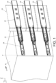
FIG. 1 is diagram showing a plurality of slide rail assemblies configured to mount a carried object to a rack according to a first embodiment of the present invention; -
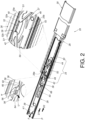
FIG. 2 is a diagram showing a second rail of a slide rail assembly being moved to a predetermined position relative to a first rail along a first predetermined direction according to the first embodiment of the present invention; -
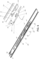
FIG. 3 is a diagram showing the second rail of the slide rail assembly located at the predetermined position relative to the first rail according to the first embodiment of the present invention; -
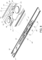
FIG. 4 is a diagram showing the second rail of the slide rail assembly being moved relative to the first rail along a second predetermined direction according to the first embodiment of the present invention; -
FIG. 5 is a diagram showing the second rail of the slide rail assembly being further moved relative to the first rail along the second predetermined direction according to the first embodiment of the present invention; -
FIG. 6 is a diagram showing an operating member of a second rail of a slide rail assembly located at a first operating position according to a second embodiment of the present invention; -
FIG. 7 is a diagram showing the operating member of the second rail of the slide rail assembly being held at a second operating position according to the second embodiment of the present invention; -
FIG. 8 is a diagram showing an operating member of a second rail of a slide rail assembly located at a first operating position according to a third embodiment of the present invention; and -
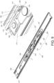
FIG. 9 is a diagram showing the operating member of the second rail of the slide rail assembly being held at a second operating position according to the third embodiment of the present invention. - As shown in
FIG. 1 , a plurality ofslide rail assemblies 20 configured to mount a carriedobject 22 to arack 24 according to a first embodiment of the present invention. Each of theslide rail assemblies 20 has substantially the same structural configuration. For example, theslide rail assembly 20 comprises afirst rail 26, asecond rail 28 and athird rail 30. Thefirst rail 26 is movably mounted between thethird rail 30 and thesecond rail 28, and thefirst rail 26 is configured to extend a moving distance of thesecond rail 28 relative to thethird rail 30. The third rail (such as an outer rail), the first rail (such as a middle rail) and the second rail 28 (such as an inner rail) are longitudinally movable relative to each other. InFIG. 1 , the X axis is a longitudinal direction (or a length direction of the slide rail), the Y axis is a transverse direction (or a lateral direction of the slide rail), and the Z axis is a vertical direction (or a height direction of the slide rail). - Furthermore, the
third rail 30 is configured to be fixedly mounted to therack 24, and thesecond rail 28 is configured to carry the carriedobject 22. Thesecond rail 28 of each of theslide rail assemblies 20 is able to be moved to a predetermined position P (such as an extended position) along a first predetermined direction D1 (such as an opening direction) relative to thefirst rail 26, such that at least one portion of the carriedobject 22 is located outside therack 24. - As shown in
FIG. 2 , thefirst rail 26 comprises ablocking feature 32. Theblocking feature 32 is directly or indirectly arranged on thefirst rail 26. Theblocking feature 32 is a protrusion in the present embodiment, but the present invention is not limited thereto. Preferably, theblocking feature 32 is arranged adjacent to anend part 26a of the first rail 26 (such as a front end part), but the present invention is not limited thereto. Theslide rail assembly 20 further comprises aworking mechanism 34, anengaging member 36 and anoperating member 38. Theworking mechanism 34, theengaging member 36 and theoperating member 38 are arranged on thesecond rail 28. Theoperating member 38 is configured to drive theworking mechanism 34 to move. In the present embodiment, theoperating member 38 is operatively connected to theworking mechanism 34 and the engaging member36. Thesecond rail 28, the workingmechanism 34, the engagingmember 36 and the operatingmember 38 together form a slide rail kit. - When the
second rail 26 is located at the predetermined position P relative to thefirst rail 26 and when the operatingmember 38 is located at a first operating position K1, the workingmechanism 34 in a first state S1 is configured to be blocked by the blockingfeature 32 of thefirst rail 26, in order to prevent thesecond rail 28 from being moved relative to thefirst rail 26 from the predetermined position P along the first predetermined direction D1 and/or a second predetermined direction D2 (such as a retracting direction) opposite to the first predetermined direction D1. - Preferably, the working
mechanism 34 comprises a pair of working members, such as first workingmember 40 and a second workingmember 42 pivotally connected to thesecond rail 28 through afirst shaft 44 and asecond shaft 46 respectively. - Preferably, the
slide rail assembly 20 further comprises at least one elastic feature, such as a firstelastic feature 48 and a secondelastic feature 50 integrated onto abase 52. Thebase 52 is arranged (such as fixed) on thesecond rail 28. Furthermore, the first workingmember 40 and the second workingmember 42 are configured to be held at the first state S1 in response to the elastic forces of the firstelastic feature 48 and the secondelastic feature 50 respectively, such that the first workingmember 40 and the second workingmember 42 are respectively blocked by two opposite ends of the blockingfeature 32 of the first rail 26 (afirst end 32a and asecond end 32b, such as a rear end and a front end, of the blocking feature 32), in order to prevent thesecond rail 28 from being moved from the predetermined position P along the first predetermined direction D1 or the second predetermined direction D2. - As shown in
FIG. 2 andFIG. 3 , when the operatingmember 38 is located at the first operating position K1 (as shown inFIG. 2 ), the workingmechanism 34 is in the first state S1 and corresponding to the blockingfeature 32 of thefirst rail 26; when the operatingmember 38 is located at a second operating position K2 (as shown inFIG. 3 ), the workingmechanism 34 is in a second state S2 and not corresponding to the blockingfeature 32 of thefirst rail 26. - Furthermore, when a user applies a force F to move the operating
member 38 from the first operating position K1 (as shown inFIG. 2 ) to a second operating position K2 (as shown inFIG. 3 ), the workingmechanism 34 is driven by the operatingmember 38 to be switched (such as being rotated) from the first state S1 (as shown inFIG. 2 ) to a second state S2 (as shown inFIG. 3 ), such that the workingmechanism 34 is no longer blocked by the blockingfeature 32, in order to allow thesecond rail 28 to move from the predetermined position P along the first predetermined direction D1 or the second predetermined direction D2. For example, thesecond rail 28 can be moved from the predetermined position P along the first predetermined direction D1 to be detached from apassage 53 of thefirst rail 26; or thesecond rail 28 can be moved from the predetermined position P along the second predetermined direction D2 to be retracted relative to thefirst rail 26. Moreover, the firstelastic feature 48 and the secondelastic feature 50 are in a state of accumulating elastic forces inFIG. 3 . - Particularly, when the operating
member 38 is located at the second operating position K2, the operatingmember 38 is engaged with the engagingmember 36, such that the operatingmember 38 is held at the second operating position K2 even the force F is no longer applied to the operatingmember 38. Therefore, the workingmechanism 34 is held at the second state S2. In other words, the workingmechanism 34 is held at a state being no longer blocked by the blockingfeature 32 of the first rail 26 (as shown inFIG. 3 ), so as to increase operating convenience for the user. - Moreover, in the aforementioned environment of the plurality of
slide rail assemblies 20 carrying the carriedobject 22 together, through using the technique of mutually engaging (positioning) the operatingmember 38 with the engagingmember 36, the operatingmember 38 of each of theslide rail assemblies 20 can be held at the second operating position K2 even the user stops applying the force F to the operating member 38 (in other words, the user does not need to apply the force F to the operatingmember 38 continuously) . As such, the workingmechanism 34 on thesecond rail 28 of each of theslide rail assemblies 20 is held at a state being no longer blocked by the blockingfeature 32 of thefirst rail 26. Therefore, the user can move thesecond rail 28 of each of theslide rail assemblies 20 from the predetermined position P along the first predetermined direction D1 to directly detach thesecond rail 28 from thepassage 53 of the first rail 26 (in other words, the carriedobject 22 can be directly detached from the rack 24) ; or the user can move thesecond rail 28 of each of theslide rail assemblies 20 from the predetermined position P along the second predetermined direction D2 to retract thesecond rail 28 relative to thefirst rail 26, so as to increase operating convenience for the user. - Preferably, the
slide rail assembly 20 further comprises a returnelastic member 54 configured to provide an elastic force to the operatingmember 38. When the operatingmember 38 is located at the second operating position K2, the returnelastic member 54 is in a state of accumulating a return elastic force J (as shown inFIG. 3 ). - Preferably, the engaging
member 36 comprises anengaging part 56, and the operatingmember 38 comprises anauxiliary feature 58. The engagingpart 56 can be a hole surrounded and defined by a plurality of wall W, and theauxiliary feature 58 can be a hook or a hook-shaped object, but the present invention is not limited thereto. When the operatingmember 38 is located at the second operating position K2, theauxiliary feature 58 of the operatingmember 38 is engaged with the engagingpart 56 of the engagingmember 36, so as to hold the operatingmember 38 at the second operating position K2 (as shown inFIG. 3 ). - Preferably, one of the engaging
member 36 and the operatingmember 38 comprises a guiding part. In the present embodiment, the engagingmember 36 and the operatingmember 38 comprise a first guidingpart 60 and a second guidingpart 62 respectively, and each of the first guidingpart 60 and the second guidingpart 62 has an inclined surface or an arc surface. Moreover, during a process of the operatingmember 38 being moved from the first operating position K1 to a second operating position K2, the operatingmember 38 is configured to contact the first guidingpart 60 of the engagingmember 36 through the second guidingpart 62, so as to guide theauxiliary feature 58 of the operatingmember 38 to be engaged with the engagingpart 56 of the engagingmember 36. - Preferably, the engaging
member 36 further comprises anelastic arm 64, and theelastic arm 64 is arranged with the engagingpart 56. During the process of the operatingmember 38 being moved from the first operating position K1 to the second operating position K2, the operatingmember 38 is configured to contact the first guidingpart 60 of the engagingmember 36 through the second guidingpart 62, so as to drive the elastic arm to deflect along a height direction U (the downward height direction U shown inFIG. 2 ), such that theelastic arm 64 accumulates an elastic force. When theauxiliary feature 58 corresponds to the engagingpart 56 of the engagingmember 36, theelastic arm 64 releases the elastic force, such that theauxiliary feature 58 is engaged with the engagingpart 56 of the engaging member 36 (as shown inFIG. 3 ) - Preferably, the engaging
member 36 is elastic. Moreover, the engagingmember 36 further comprises a connectingpart 66 fixed to thesecond rail 28, and theelastic arm 64 is extended a predetermined longitudinal length from the connectingpart 66. - Preferably, the
second rail 28 comprises afirst wall 25a, asecond wall 25b and alongitudinal wall 27 connected between thefirst wall 25a and thesecond wall 25b of thesecond rail 28. When the workingmechanism 34 is in the first state S1, the workingmechanism 34 is adjacent to thefirst wall 25a of the second rail 28 (as shown inFIG. 2 ); when the workingmechanism 34 is in the second state S2, the workingmechanism 34 is away from thefirst wall 25a of the second rail 28 (as shown inFIG. 3 ). - As shown in
FIG. 3 ,FIG. 4 andFIG. 5 , the engagingmember 36 further comprises a disengagingpart 68 corresponding to the blockingfeature 32 of thefirst rail 26. The disengagingpart 68 has an inclined surface or an arc surface. Preferably, theelastic arm 64 is arranged with the disengagingpart 68. When thesecond rail 28 is moved from the predetermined position P along the second predetermined direction D2 relative to the first rail 26 (as shown inFIG. 3 ), theelastic arm 64 of the engagingmember 36 is configured to be deflected by a predetermined angle along the height direction U (such as being deflected downward by the predetermined angle shown inFIG. 5 ) through mutual contact between the blocking feature 32 (thesecond end 32b of the blocking feature 32) of thefirst rail 26 and the disengagingpart 68 of the engagingmember 36, in order to disengage theauxiliary feature 58 of the operatingmember 38 from the engagingpart 56 of the engagingmember 36. Meanwhile, the returnelastic member 54 is configured to release the return elastic force J along the second predetermined direction D2, such that the operatingmember 38 is driven to return to the first operating position K1 (as shown inFIG. 5 ) from the second operating position K2 (as shown inFIG. 4 ) in response to the return elastic force J. Accordingly, the firstelastic feature 48 and the secondelastic feature 50 are configured to release the elastic forces, and the first workingmember 40 and the second workingmember 42 are held at the first state S1 again (as shown inFIG. 5 ) in response to the elastic forces released by the firstelastic feature 48 and the secondelastic feature 50. -
FIG. 6 andFIG. 7 show asecond rail 200 of a slide rail assembly according to a second embodiment of the present invention. Similar to the first embodiment, when the user applies a force F' to move an operatingmember 202 of the second embodiment from a first operating position K1' (as shown inFIG. 6 ) to a second operating position K2' (as shown inFIG. 7 ), the operatingmember 202 is configured to be engaged with an engagingmember 204, so as to hold the operatingmember 202 at the second operating position K2', in order to hold aworking mechanism 206 in a second state S2' (as shown inFIG. 7 ). - A difference between the second embodiment and the first embodiment substantially lies in structural configuration and interactive relationship between the operating
member 202 and the engagingmember 204. - Furthermore, the engaging
member 204 comprises a connectingpart 208, anelastic arm 210, anengaging part 212 and a disengagingpart 214. The connectingpart 208 is fixed to thesecond rail 200. Theelastic arm 210 is extended a predetermined longitudinal length from the connectingpart 208. Theelastic arm 210 is arranged with theengaging part 212 and the disengagingpart 214. Theengaging part 212 can be a hook or a hook-shaped object, but the present invention is not limited thereto. - Preferably, the
engaging part 212 of the engagingmember 204 is arranged with anauxiliary guiding section 216, and theauxiliary guiding section 216 has an inclined surface or an arc surface. - Preferably, the disengaging
part 214 has an inclined surface or an arc surface. - On the other hand, the operating
member 202 comprises anauxiliary feature 218, and theauxiliary feature 218 has a vertical wall, but the present invention is not limited thereto. When the operatingmember 202 is located at the second operating position K2', theauxiliary feature 218 of the operatingmember 202 is configured to be engaged with theengaging part 212 of the engagingmember 204, so as to hold the operatingmember 202 at the second operating position K2' (as shown inFIG. 7 ). - Preferably, the operating
member 202 is formed with a first space M1. Theengaging part 212 of the engagingmember 204 is configured to penetrate through the operatingmember 202 from a first side L1 of the operatingmember 202 to a second side L2 of the operatingmember 202 through the first space M1. The first side L1 and the second side L2 are two opposite sides (as shown inFIG. 6 ). - The operating
member 202 is further formed with a second space M2. The disengagingpart 214 of the engagingmember 204 is configured to penetrate through the operatingmember 202 from the first side L1 of the operatingmember 202 to the second side L2 of the operatingmember 202 through the second space M2 (as shown inFIG. 6 ). - When the user applies a force F' to the operating
member 202 to move the operatingmember 202 from the first operating position K1' (as shown inFIG. 6 ) to the second operating position K2' (as shown inFIG. 7 ), the working mechanism 206 (such as a first workingmember 220 and a second workingmember 222 of the working mechanism 206) is driven by the operatingmember 202 to be switched (such as being rotated) from a first state S1' (as shown inFIG. 6 ) to a second state S2' (as shown inFIG. 7 ), such that the working mechanism is no longer blocked by the blockingfeature 32 of thefirst rail 26, so as to allow thesecond rail 200 to move from the predetermined position P along the first predetermined direction D1 and the second predetermined direction D2 relative to thefirst rail 26. Such configuration is identical to the first embodiment, for simplification, no further illustration is provided. In addition, a firstelastic feature 224 and a secondelastic feature 226 are in a state of accumulating elastic forces inFIG. 7 . - Particularly, when the operating
member 202 is located at the second operating position K2', the operatingmember 202 is engaged with the engagingmember 204, such that the operatingmember 202 is held at the second operating position K2' even the force F' is no longer applied to the operatingmember 202. Therefore, the workingmechanism 206 is held at the second state S2'. In other words, the workingmechanism 206 is held at a state being no longer blocked by the blockingfeature 32 of the first rail 26 (as shown inFIG. 7 ), so as to increase operating convenience for the user. - Preferably, when the operating
member 202 is located at the second operating position K2', theauxiliary feature 218 of the operatingmember 202 is engaged with theengaging part 212 of the engagingmember 204, so as to hold the operatingmember 202 at the second operating position K2'. - Preferably, during a process of the operating
member 202 being moved from the first operating position K1' to the second operating position K2', theelastic arm 210 is configured to be deflected along a transverse direction T (the transverse direction T shown inFIG. 6 ) through mutual contact between theauxiliary guiding section 216 of the engagingmember 204 and the operating member 202 (aninner wall 228 in the first space M1), such that theelastic arm 210 accumulates an elastic force. When theauxiliary feature 218 corresponds to theengaging part 212 of the engagingmember 204, theelastic arm 210 releases the elastic force, such that theauxiliary feature 218 of the operatingmember 202 is engaged with theengaging part 212 of the engaging member 204 (as shown inFIG. 7 ). - More particularly, similar to the first embodiment, the disengaging
part 214 of the engagingmember 204 of the second embodiment corresponds to the blocking feature 32 (thesecond end 32b of the blocking feature 32) of thefirst rail 26. When thesecond rail 200 is moved from the predetermined position P along the second predetermined direction D2 relative to thefirst rail 26, theelastic arm 210 of the engagingmember 204 is configured to be deflected by a predetermined angle along the transverse direction T through mutual contact between the blocking feature 32 (thesecond end 32b of the blocking feature 32) of thefirst rail 26 and the disengagingpart 214 of the engagingmember 204, in order to disengage theauxiliary feature 218 of the operatingmember 202 from theengaging part 212 of the engagingmember 204. Meanwhile, a returnelastic member 230 is configured to release a return elastic force J' along the second predetermined direction D2, such that the operatingmember 202 is driven to return to the first operating position K1' (as shown inFIG. 6 ) from the second operating position K2' (as shown inFIG. 7 ) in response to the return elastic force J' . Accordingly, the firstelastic feature 224 and the secondelastic feature 226 are configured to release the elastic forces, and the working mechanism 206 (the first workingmember 40 and the second working member 42) is held at the first state S1' again (as shown inFIG. 6 ) in response to the elastic forces released by the firstelastic feature 224 and the secondelastic feature 226. -
FIG. 8 andFIG. 9 show asecond rail 300 of a slide rail assembly according to a third embodiment of the present invention. Similar to the first embodiment, when the user applies a force F" to move an operatingmember 302 of the second embodiment from a first operating position K1" (as shown inFIG. 8 ) to a second operating position K2" (as shown inFIG. 9 ), the operatingmember 302 is configured to be engaged with an engagingmember 304, so as to hold the operatingmember 302 at the second operating position K2", in order to hold aworking mechanism 306 in a second state S2" (as shown inFIG. 9 ). - A difference between the third embodiment and the first embodiment substantially lies in structural configuration and interactive relationship between the operating
member 302 and the engagingmember 304. - Furthermore, the engaging
member 304 comprises a connectingpart 308, anelastic arm 310, anengaging part 312 and a disengagingpart 314. Preferably, the engagingmember 304 further comprises a supporting part 315.The connectingpart 308 is movably mounted to thesecond rail 300. In the present embodiment, the connectingpart 308 is pivotally connected to thesecond rail 300 through anauxiliary shaft 313. Theelastic arm 310 is extended a predetermined longitudinal length from a top portion of the connectingpart 308. Theelastic arm 310 is arranged with theengaging part 312 and the disengagingpart 314. The supportingpart 315 is extended a predetermined longitudinal length from a bottom portion of the connectingpart 308. The supportingpart 315 and theelastic arm 310 are substantially parallel to each other. The supportingpart 315 and thesecond rail 300 are configured to support and abut against each other, in order to increase stability of positioning the engagingmember 304. A predetermined gap G is defined between the supportingpart 315 and connecting part 308 (as shown inFIG. 8 ). - Preferably, the
engaging part 312 can be a hole surrounded and defined by a plurality of wall W", and anauxiliary feature 318 of the operatingmember 302 can be a hook or a hook-shaped object, but the present invention is not limited thereto. - Preferably, the disengaging
part 314 has an inclined surface or an arc surface. - Preferably, one of the engaging
member 304 and the operatingmember 302 comprises a guiding part. In the present embodiment, the engagingmember 304 and the operatingmember 302 comprise a first guidingpart 320 and asecond guiding part 322 respectively, and each of the first guidingpart 320 and thesecond guiding part 322 has an inclined surface or an arc surface. - When the operating
member 302 is located at the second operating position K2", theauxiliary feature 318 of the operatingmember 302 is engaged with theengaging part 312 of the engagingmember 304, so as to hold the operatingmember 302 at the second operating position K2" (as shown inFIG. 9 ). - When the user applies the force F" to the operating
member 302 to move the operatingmember 302 from the first operating position K1" (as shown inFIG. 8 ) to the second operating position K2" (as shown inFIG. 9 ), the working mechanism 306 (such as a first workingmember 328 and a second workingmember 332 of the working mechanism 306) is driven by the operatingmember 302 to be switched (such as being rotated) from the first state (as shown inFIG. 2 ) to a second state (as shown inFIG. 3 ), such that the workingmechanism 306 is no longer blocked by the blockingfeature 32 of thefirst rail 26, in order to allow thesecond rail 300 to move from the predetermined position P along the first predetermined direction D1 or the second predetermined direction D2. Such configuration is identical to the first embodiment, for simplification, no further illustration is provided. In addition, a firstelastic feature 324 and a secondelastic feature 326 are in a state of accumulating elastic forces inFIG. 9 . - Particularly, when the operating
member 302 is located at the second operating position K2", the operatingmember 302 is engaged with the engagingmember 304, such that the operatingmember 302 is held at the second operating position K2" even the force F" is no longer applied to the operatingmember 302. Therefore, the workingmechanism 306 is held at the second state S2". In other words, the workingmechanism 306 is held at a state being no longer blocked by the blockingfeature 32 of the first rail 26 (as shown inFIG. 9 ), so as to increase operating convenience for the user. - Preferably, when the operating
member 302 is located at the second operating position K2", theauxiliary feature 318 of the operatingmember 302 is engaged with theengaging part 312 of the engagingmember 304, so as to hold the operatingmember 302 at the second operating position K2". - Preferably, during a process of the operating
member 302 being moved from the first operating position K1" to the second operating position K2", theelastic arm 310 is configured to be deflected along a height direction U" (the downward height direction U" shown inFIG. 8 ) through thesecond guiding part 322 of the operatingmember 302 contacting the first guidingpart 320 of the engagingmember 304, so as to drive the connectingpart 308 of the engagingmember 304 to rotate toward the supportingpart 315 along a predetermined moving direction Q to provide a buffering effect, in order to prevent deformation or damage of the engagingmember 304 due to excessive force. Meanwhile, the elastic arm accumulates an elastic force. When theauxiliary feature 318 of the operatingmember 302 corresponds to theengaging part 312 of the engagingmember 304, the elastic arm releases the elastic force, such that theauxiliary feature 318 is engaged with theengaging part 312 of the engaging member 304 (as shown inFIG. 9 ). - More particularly, similar to the first embodiment, the disengaging
part 314 of the engagingmember 304 of the third embodiment corresponds to the blocking feature 32 (thesecond end 32b of the blocking feature 32) of thefirst rail 26. When thesecond rail 300 is moved from the predetermined position P along the second predetermined direction D2 relative to thefirst rail 26, theelastic arm 310 of the engagingmember 304 is configured to be deflected by a predetermined angle along the height direction U" through mutual contact between the blocking feature 32 (thesecond end 32b of the blocking feature 32) of thefirst rail 26 and the disengagingpart 314 of the engagingmember 304, in order to disengage theauxiliary feature 318 of the operatingmember 302 from theengaging part 312 of the engagingmember 304. Meanwhile, a returnelastic member 330 is configured to release a return elastic force J" along the second predetermined direction D2, such that the operatingmember 302 is driven to return to the first operating position K1" (as shown inFIG. 8 ) from the second operating position K2" (as shown inFIG. 9 ) in response to the return elastic force J". Accordingly, the firstelastic feature 324 and the secondelastic feature 326 are configured to release the elastic forces, and the working mechanism 306 (the first workingmember 328 and the second working member 332) is held at the first state S1" again (as shown inFIG. 8 ) in response to the elastic forces released by the firstelastic feature 324 and the secondelastic feature 326. - Therefore, the slide rail assembly and the slide rail kit according to the embodiments of the present invention have the following technical features:
- 1. Different from the linkage rod of the prior art which cannot be held at a predetermined operating position after being operated by the user, the operating
member member member mechanism mechanism feature 32 of thefirst rail 26. Therefore, thesecond rail first rail 20 or moved from the predetermined position P along the second predetermined direction D2 to be retracted relative to thefirst rail 20, so as to increase operating convenience for the user (single person) to operate alone. - 2. In the first embodiment, the engaging
member 36 is connected (fixed) to thesecond rail 28 through the connectingpart 66, and the moving direction of theelastic arm 64 of the engagingmember 36 is the height direction U relative to thesecond rail 28; in the second embodiment, the engagingmember 204 is connected (fixed) to thesecond rail 28 through the connectingpart 208, and the moving direction of theelastic arm 210 of the engagingmember 204 is the transverse direction T relative to thesecond rail 200; in the third embodiment, the engagingmember 304 is movably mounted (pivotally connected) to thesecond rail 300 through the connectingpart 308.
Claims (15)
- A slide rail assembly (20), comprising:a first rail (26) comprising a blocking feature (32);a second rail (28, 200, 300) longitudinally movable relative to the first rail (26);a third rail (30);a working mechanism (34, 206, 306) and an engaging member (36, 204, 304) arranged on the second rail (28, 200, 300); andan operating member (38, 202, 302) arranged on the second rail (28, 200, 300) and configured to drive the working mechanism (34, 206, 306);wherein the first rail (26) is movably mounted between the third rail (30) and the second rail (28, 200, 300), and the first rail (26) is configured to extend a moving distance of the second rail (28, 200, 300) relative to the third rail (30);wherein when the second rail (28, 200, 300) is moved to a predetermined position relative to the first rail (26) along a first predetermined direction, the working mechanism (34, 206, 306) in a first state is configured to be blocked by the blocking feature (32);wherein the working mechanism (34, 206, 306) comprises a pair of working members ((40, 42), (220, 222), (320, 322)) pivotally connected to the second rail (28, 200, 300), the pair of working members ((40, 42), (220, 222), (320, 322)) are configured to be held at the first state in response to elastic force of at least one elastic feature (48, 224, 50, 226);wherein when the operating member (38, 202, 302) is moved from a first operating position to a second operating position, the working mechanism (34, 206, 306) is driven by the operating member (38, 202, 302) to switch to a second state to be no longer blocked by the blocking feature (32), such that the second rail (28, 200, 300) is movable relative to the first rail (26) from the predetermined position along the first predetermined direction to be detached from the first rail (26) or along a second predetermined direction opposite to the first predetermined direction to be retracted relative to the first rail (26);wherein when the operating member (38, 202, 302) is located at the second operating position, the operating member (38, 202, 302) is engaged with the engaging member (36, 204, 304) to be held at the second operating position.
- The slide rail assembly of claim 1, further characterized by a return elastic member (54, 230, 330) configured to provide elastic force to the operating member (38, 202, 302).
- The slide rail assembly of claim 1 or 2, characterized in that the engaging member (36, 204, 304) comprises an engaging part (56, 212, 312), and the operating member (38, 202, 302) comprises an auxiliary feature (58); wherein when the operating member (38, 202, 302) is located at the second operating position, the auxiliary feature (58) is configured to engage with the engaging part (56, 212, 312) of the engaging member (36, 204, 304) to hold the operating member (38, 202, 302) at the second operating position.
- The slide rail assembly of claim 3, characterized in that the engaging member (36, 204, 304) further comprises a disengaging part (68, 214, 314) corresponding to the blocking feature (32) of the first rail (26); wherein when the second rail (28, 200, 300) is moved relative to the first rail (26) along the second predetermined direction, the operating member (38, 202, 302) is disengaged from the engaging member (36, 204, 304) through mutual contact between the blocking feature (32) of the first rail (26) and the disengaging part (68, 214, 314) of the engaging member (36, 204, 304).
- The slide rail assembly of claim 4, characterized in that the engaging member (36, 204, 304) further comprises an elastic arm (64, 210, 310), and the elastic arm (64, 210, 310) is arranged with the engaging part (56, 212, 312) and the disengaging part (68, 214, 314).
- The slide rail assembly of claim 5, characterized in that the engaging member (36, 204) further comprises a connecting part (66, 208) fixed to the second rail (28, 200), and the elastic arm (64, 210) is extended from the connecting part (66, 208).
- The slide rail assembly of claim 6, characterized in that the elastic arm (64, 210) is configured to move along a height direction or a transverse direction of the slide rail assembly (20) .
- The slide rail assembly of claim 5, characterized in that the engaging member (304) further comprises a connecting part (308) movably mounted to the second rail (300), and the elastic arm (310) is extended from the connecting part (308).
- The slide rail assembly of claim 8, characterized in that the connecting part (308) is pivotally connected to the second rail (300) .
- A rack system, comprising:a rack (24);a carried object (22); anda plurality of slide rail assemblies (20) arranged on one side of the carried object (22) and configured to mount the carried object (22) to the rack (24), each of the slide rail assemblies (20) comprising:a first rail (26) comprising a blocking feature (32);a second rail (28, 200, 300) movable relative to the first rail (26) and configured to carry the carried object (22) ;a third rail (30) configured to be mounted to the rack (24);a working mechanism (34, 206, 306) and an engaging member (36, 204, 304) arranged on the second rail (28, 200, 300), wherein the engaging member (36, 204, 304) comprises an engaging part (56, 212, 312); andan operating member (38, 202, 302) arranged on the second rail (28, 200, 300) and configured to drive the working mechanism (34, 206, 306), the operating member (38, 202, 302) comprising an auxiliary feature (58);wherein the first rail (26) is movably mounted between the third rail (30) and the second rail (28, 200, 300), and the first rail (26) is configured to extend a moving distance of the second rail (28, 200, 300) relative to the third rail (30);wherein the working mechanism (34, 206, 306) comprises a pair of working members ((40, 42), (220, 222), (320, 322)) pivotally connected to the second rail (28, 200, 300), the pair of working members ((40, 42), (220, 222), (320, 322)) are configured to be held at a first state in response to elastic force of at least one elastic feature (48, 224, 50, 226);wherein when the operating member (38, 202, 302) is located at a first operating position, the working mechanism (34, 206, 306) is in the first state and corresponding to the blocking feature (32) of the first rail (26); when the operating member (38, 202, 302) is located at a second operating position, the working mechanism (34, 206, 306) is in a second state and not corresponding to the blocking feature (32) of the first rail (26);wherein when the second rail (28, 200, 300) is moved relative to the first rail (26) along an opening direction to an extended position and when the operating member (38, 202, 302) is located at the first operating position, the working mechanism (34, 206, 306) and the blocking feature (32) are configured to block each other;wherein when the operating member (38, 202, 302) is located at the second operating position, the working mechanism (34, 206, 306) and the blocking feature (32) no longer block each other such that the second rail (28, 200, 300) is movable relative to the first rail (26) from the predetermined position along the first predetermined direction to be detached from the first rail (26) or along a second predetermined direction opposite to the first predetermined direction to be retracted relative to the first rail (26), and the auxiliary feature (58) of the operating member (38, 202, 302) is configured to engage with the engaging part (56, 212, 312) of the engaging member (36, 204, 304) in order to hold the operating member (38, 202, 302) at the second operating position.
- The rack system of claim 10, further characterized by a return elastic member (54, 230, 330) configured to provide elastic force to the operating member (38, 202, 302).
- The rack system of claim 10 or 11, characterized in that the engaging member (36, 204, 304) further comprises a disengaging part (68, 214, 314) corresponding to the blocking feature (32) of the first rail (26); wherein when the second rail (28, 200, 300) is moved relative to the first rail (26) along a retracted direction, the auxiliary feature (58) of the operating member (38, 202, 302) is disengaged from the engaging part (56, 212, 312) of the engaging member (36, 204, 304) through mutual contact between the blocking feature (32) of the first rail (26) and the disengaging part (68, 214, 314) of the engaging member (36, 204, 304) .
- The rack system of claim 12, characterized in that the engaging member (36, 204, 304) is fixedly or movably connected to the second rail (28, 200, 300).
- The rack system of claim 13, characterized in that the second rail (28, 200, 300) is longitudinally movable relative to the first rail (26), the engaging member (36, 204, 304) further comprises an elastic arm (64, 210, 310), and the elastic arm (64, 210, 310) is arranged with the engaging part (56, 212, 312) and the disengaging part (68, 214, 314).
- The rack system of claim 14, characterized in that the elastic arm (64, 210, 310) is configured to move along a height direction or a transverse direction of the slide rail assembly (20).
Applications Claiming Priority (1)
| Application Number | Priority Date | Filing Date | Title |
|---|---|---|---|
| TW112123749A TWI829603B (en) | 2023-06-21 | 2023-06-21 | Slide rail assembly and slide rail kit thereof |
Publications (2)
| Publication Number | Publication Date |
|---|---|
| EP4480344A1 true EP4480344A1 (en) | 2024-12-25 |
| EP4480344B1 EP4480344B1 (en) | 2025-07-02 |
Family
ID=89474159
Family Applications (1)
| Application Number | Title | Priority Date | Filing Date |
|---|---|---|---|
| EP24150516.3A Active EP4480344B1 (en) | 2023-06-21 | 2024-01-05 | Slide rail assembly |
Country Status (4)
| Country | Link |
|---|---|
| US (1) | US12303028B2 (en) |
| EP (1) | EP4480344B1 (en) |
| JP (1) | JP7800939B2 (en) |
| TW (1) | TWI829603B (en) |
Families Citing this family (1)
| Publication number | Priority date | Publication date | Assignee | Title |
|---|---|---|---|---|
| TWI916283B (en) | 2025-06-26 | 2026-02-21 | 川湖科技股份有限公司 | Slide rail assembly |
Citations (2)
| Publication number | Priority date | Publication date | Assignee | Title |
|---|---|---|---|---|
| US6935710B2 (en) * | 2003-03-05 | 2005-08-30 | King Slide Works Co., Ltd. | Two-way retainer for a slide track assembly of drawers |
| US20090096340A1 (en) * | 2007-10-12 | 2009-04-16 | Ken-Ching Chen | Locating structure for a slide assembly |
Family Cites Families (7)
| Publication number | Priority date | Publication date | Assignee | Title |
|---|---|---|---|---|
| TW589968U (en) * | 2003-03-05 | 2004-06-01 | King Slide Works Co Ltd | Two-way retainer for a sliding track assembly of drawers |
| US7413269B2 (en) * | 2004-08-04 | 2008-08-19 | King Slide Works Co., Ltd. | Synchronous system for a three-stage ball bearing slide |
| TWM299509U (en) * | 2006-01-18 | 2006-10-21 | Nan Juen Int Co Ltd | Wedging mechanism for slide rail of drawer |
| CN201001516Y (en) * | 2007-01-10 | 2008-01-09 | 鸿富锦精密工业(深圳)有限公司 | Sliding rail device |
| TWI658803B (en) * | 2017-12-28 | 2019-05-11 | 川湖科技股份有限公司 | Slide rail assembly and rail kit thereof |
| TWI721493B (en) * | 2019-07-12 | 2021-03-11 | 川湖科技股份有限公司 | Slide rail assembly |
| TWI737555B (en) | 2020-12-22 | 2021-08-21 | 川湖科技股份有限公司 | Slide rail assembly and slide rail kit thereof |
-
2023
- 2023-06-21 TW TW112123749A patent/TWI829603B/en active
- 2023-11-14 US US18/508,846 patent/US12303028B2/en active Active
-
2024
- 2024-01-05 EP EP24150516.3A patent/EP4480344B1/en active Active
- 2024-02-14 JP JP2024019922A patent/JP7800939B2/en active Active
Patent Citations (2)
| Publication number | Priority date | Publication date | Assignee | Title |
|---|---|---|---|---|
| US6935710B2 (en) * | 2003-03-05 | 2005-08-30 | King Slide Works Co., Ltd. | Two-way retainer for a slide track assembly of drawers |
| US20090096340A1 (en) * | 2007-10-12 | 2009-04-16 | Ken-Ching Chen | Locating structure for a slide assembly |
Also Published As
| Publication number | Publication date |
|---|---|
| EP4480344B1 (en) | 2025-07-02 |
| TWI829603B (en) | 2024-01-11 |
| TW202500057A (en) | 2025-01-01 |
| US20240423365A1 (en) | 2024-12-26 |
| US12303028B2 (en) | 2025-05-20 |
| JP7800939B2 (en) | 2026-01-16 |
| JP2025003286A (en) | 2025-01-09 |
Similar Documents
| Publication | Publication Date | Title |
|---|---|---|
| US11060558B2 (en) | Slide rail assembly and operation method thereof | |
| US9992906B2 (en) | Slide rail assembly and operation method thereof | |
| US10244868B2 (en) | Slide rail assembly | |
| US10617208B2 (en) | Slide rail assembly | |
| US10398228B2 (en) | Slide rail assembly | |
| EP3307038B1 (en) | Slide rail assembly | |
| EP3461244B1 (en) | Slide rail assembly and driving mechanism thereof | |
| US11064807B2 (en) | Slide rail assembly | |
| EP4480344B1 (en) | Slide rail assembly | |
| EP4570126A1 (en) | Slide rail assembly | |
| EP3307037B1 (en) | Slide rail assembly | |
| US12378994B2 (en) | Slide rail assembly | |
| JP7800927B2 (en) | Slide Rail Mechanism | |
| JP7592952B2 (en) | Slide Rail Mechanism | |
| US11067290B2 (en) | Cabinet and slide rail kit thereof | |
| EP4616761B1 (en) | Slide rail mechanism | |
| CN119196170A (en) | Slide rail assembly and slide rail external member thereof | |
| JP2026079670A (en) | Slide rail assembly | |
| JP2025043256A (en) | Slide Rail Assembly |
Legal Events
| Date | Code | Title | Description |
|---|---|---|---|
| PUAI | Public reference made under article 153(3) epc to a published international application that has entered the european phase |
Free format text: ORIGINAL CODE: 0009012 |
|
| STAA | Information on the status of an ep patent application or granted ep patent |
Free format text: STATUS: REQUEST FOR EXAMINATION WAS MADE |
|
| 17P | Request for examination filed |
Effective date: 20240813 |
|
| AK | Designated contracting states |
Kind code of ref document: A1 Designated state(s): AL AT BE BG CH CY CZ DE DK EE ES FI FR GB GR HR HU IE IS IT LI LT LU LV MC ME MK MT NL NO PL PT RO RS SE SI SK SM TR |
|
| GRAP | Despatch of communication of intention to grant a patent |
Free format text: ORIGINAL CODE: EPIDOSNIGR1 |
|
| STAA | Information on the status of an ep patent application or granted ep patent |
Free format text: STATUS: GRANT OF PATENT IS INTENDED |
|
| INTG | Intention to grant announced |
Effective date: 20250325 |
|
| RIC1 | Information provided on ipc code assigned before grant |
Ipc: A47B 88/423 20170101ALN20250317BHEP Ipc: A47B 88/57 20170101ALI20250317BHEP Ipc: A47B 88/53 20170101AFI20250317BHEP |
|
| GRAS | Grant fee paid |
Free format text: ORIGINAL CODE: EPIDOSNIGR3 |
|
| GRAA | (expected) grant |
Free format text: ORIGINAL CODE: 0009210 |
|
| STAA | Information on the status of an ep patent application or granted ep patent |
Free format text: STATUS: THE PATENT HAS BEEN GRANTED |
|
| AK | Designated contracting states |
Kind code of ref document: B1 Designated state(s): AL AT BE BG CH CY CZ DE DK EE ES FI FR GB GR HR HU IE IS IT LI LT LU LV MC ME MK MT NL NO PL PT RO RS SE SI SK SM TR |
|
| REG | Reference to a national code |
Ref country code: GB Ref legal event code: FG4D |
|
| REG | Reference to a national code |
Ref country code: CH Ref legal event code: EP |
|
| REG | Reference to a national code |
Ref country code: DE Ref legal event code: R096 Ref document number: 602024000248 Country of ref document: DE |
|
| REG | Reference to a national code |
Ref country code: IE Ref legal event code: FG4D |
|
| REG | Reference to a national code |
Ref country code: NL Ref legal event code: MP Effective date: 20250702 |
|
| PG25 | Lapsed in a contracting state [announced via postgrant information from national office to epo] |
Ref country code: PT Free format text: LAPSE BECAUSE OF FAILURE TO SUBMIT A TRANSLATION OF THE DESCRIPTION OR TO PAY THE FEE WITHIN THE PRESCRIBED TIME-LIMIT Effective date: 20251103 |
|
| PG25 | Lapsed in a contracting state [announced via postgrant information from national office to epo] |
Ref country code: NL Free format text: LAPSE BECAUSE OF FAILURE TO SUBMIT A TRANSLATION OF THE DESCRIPTION OR TO PAY THE FEE WITHIN THE PRESCRIBED TIME-LIMIT Effective date: 20250702 |
|
| REG | Reference to a national code |
Ref country code: AT Ref legal event code: MK05 Ref document number: 1808221 Country of ref document: AT Kind code of ref document: T Effective date: 20250702 |
|
| PG25 | Lapsed in a contracting state [announced via postgrant information from national office to epo] |
Ref country code: IS Free format text: LAPSE BECAUSE OF FAILURE TO SUBMIT A TRANSLATION OF THE DESCRIPTION OR TO PAY THE FEE WITHIN THE PRESCRIBED TIME-LIMIT Effective date: 20251102 |
|
| PG25 | Lapsed in a contracting state [announced via postgrant information from national office to epo] |
Ref country code: NO Free format text: LAPSE BECAUSE OF FAILURE TO SUBMIT A TRANSLATION OF THE DESCRIPTION OR TO PAY THE FEE WITHIN THE PRESCRIBED TIME-LIMIT Effective date: 20251002 |
|
| REG | Reference to a national code |
Ref country code: LT Ref legal event code: MG9D |
|
| PG25 | Lapsed in a contracting state [announced via postgrant information from national office to epo] |
Ref country code: AT Free format text: LAPSE BECAUSE OF FAILURE TO SUBMIT A TRANSLATION OF THE DESCRIPTION OR TO PAY THE FEE WITHIN THE PRESCRIBED TIME-LIMIT Effective date: 20250702 |
|
| PG25 | Lapsed in a contracting state [announced via postgrant information from national office to epo] |
Ref country code: FI Free format text: LAPSE BECAUSE OF FAILURE TO SUBMIT A TRANSLATION OF THE DESCRIPTION OR TO PAY THE FEE WITHIN THE PRESCRIBED TIME-LIMIT Effective date: 20250702 |
|
| PG25 | Lapsed in a contracting state [announced via postgrant information from national office to epo] |
Ref country code: HR Free format text: LAPSE BECAUSE OF FAILURE TO SUBMIT A TRANSLATION OF THE DESCRIPTION OR TO PAY THE FEE WITHIN THE PRESCRIBED TIME-LIMIT Effective date: 20250702 |
|
| PG25 | Lapsed in a contracting state [announced via postgrant information from national office to epo] |
Ref country code: GR Free format text: LAPSE BECAUSE OF FAILURE TO SUBMIT A TRANSLATION OF THE DESCRIPTION OR TO PAY THE FEE WITHIN THE PRESCRIBED TIME-LIMIT Effective date: 20251003 |
|
| PG25 | Lapsed in a contracting state [announced via postgrant information from national office to epo] |
Ref country code: CZ Free format text: LAPSE BECAUSE OF FAILURE TO SUBMIT A TRANSLATION OF THE DESCRIPTION OR TO PAY THE FEE WITHIN THE PRESCRIBED TIME-LIMIT Effective date: 20250702 Ref country code: SE Free format text: LAPSE BECAUSE OF FAILURE TO SUBMIT A TRANSLATION OF THE DESCRIPTION OR TO PAY THE FEE WITHIN THE PRESCRIBED TIME-LIMIT Effective date: 20250702 |
|
| PGFP | Annual fee paid to national office [announced via postgrant information from national office to epo] |
Ref country code: IE Payment date: 20251203 Year of fee payment: 3 |
|
| PG25 | Lapsed in a contracting state [announced via postgrant information from national office to epo] |
Ref country code: LV Free format text: LAPSE BECAUSE OF FAILURE TO SUBMIT A TRANSLATION OF THE DESCRIPTION OR TO PAY THE FEE WITHIN THE PRESCRIBED TIME-LIMIT Effective date: 20250702 |
|
| PG25 | Lapsed in a contracting state [announced via postgrant information from national office to epo] |
Ref country code: PL Free format text: LAPSE BECAUSE OF FAILURE TO SUBMIT A TRANSLATION OF THE DESCRIPTION OR TO PAY THE FEE WITHIN THE PRESCRIBED TIME-LIMIT Effective date: 20250702 Ref country code: BG Free format text: LAPSE BECAUSE OF FAILURE TO SUBMIT A TRANSLATION OF THE DESCRIPTION OR TO PAY THE FEE WITHIN THE PRESCRIBED TIME-LIMIT Effective date: 20250702 |
|
| PG25 | Lapsed in a contracting state [announced via postgrant information from national office to epo] |
Ref country code: RS Free format text: LAPSE BECAUSE OF FAILURE TO SUBMIT A TRANSLATION OF THE DESCRIPTION OR TO PAY THE FEE WITHIN THE PRESCRIBED TIME-LIMIT Effective date: 20251002 |
|
| PG25 | Lapsed in a contracting state [announced via postgrant information from national office to epo] |
Ref country code: ES Free format text: LAPSE BECAUSE OF FAILURE TO SUBMIT A TRANSLATION OF THE DESCRIPTION OR TO PAY THE FEE WITHIN THE PRESCRIBED TIME-LIMIT Effective date: 20250702 |
|
| PG25 | Lapsed in a contracting state [announced via postgrant information from national office to epo] |
Ref country code: SM Free format text: LAPSE BECAUSE OF FAILURE TO SUBMIT A TRANSLATION OF THE DESCRIPTION OR TO PAY THE FEE WITHIN THE PRESCRIBED TIME-LIMIT Effective date: 20250702 |
|
| PG25 | Lapsed in a contracting state [announced via postgrant information from national office to epo] |
Ref country code: DK Free format text: LAPSE BECAUSE OF FAILURE TO SUBMIT A TRANSLATION OF THE DESCRIPTION OR TO PAY THE FEE WITHIN THE PRESCRIBED TIME-LIMIT Effective date: 20250702 |
|
| PGFP | Annual fee paid to national office [announced via postgrant information from national office to epo] |
Ref country code: DE Payment date: 20251216 Year of fee payment: 3 |
|
| PG25 | Lapsed in a contracting state [announced via postgrant information from national office to epo] |
Ref country code: IT Free format text: LAPSE BECAUSE OF FAILURE TO SUBMIT A TRANSLATION OF THE DESCRIPTION OR TO PAY THE FEE WITHIN THE PRESCRIBED TIME-LIMIT Effective date: 20250702 |
|
| PG25 | Lapsed in a contracting state [announced via postgrant information from national office to epo] |
Ref country code: EE Free format text: LAPSE BECAUSE OF FAILURE TO SUBMIT A TRANSLATION OF THE DESCRIPTION OR TO PAY THE FEE WITHIN THE PRESCRIBED TIME-LIMIT Effective date: 20250702 Ref country code: SK Free format text: LAPSE BECAUSE OF FAILURE TO SUBMIT A TRANSLATION OF THE DESCRIPTION OR TO PAY THE FEE WITHIN THE PRESCRIBED TIME-LIMIT Effective date: 20250702 |
|
| PLBE | No opposition filed within time limit |
Free format text: ORIGINAL CODE: 0009261 |
|
| STAA | Information on the status of an ep patent application or granted ep patent |
Free format text: STATUS: NO OPPOSITION FILED WITHIN TIME LIMIT |