EP4480339A1 - Fastening device - Google Patents
Fastening device Download PDFInfo
- Publication number
- EP4480339A1 EP4480339A1 EP24183219.5A EP24183219A EP4480339A1 EP 4480339 A1 EP4480339 A1 EP 4480339A1 EP 24183219 A EP24183219 A EP 24183219A EP 4480339 A1 EP4480339 A1 EP 4480339A1
- Authority
- EP
- European Patent Office
- Prior art keywords
- torque
- knob
- fastening device
- spool
- engaging
- Prior art date
- Legal status (The legal status is an assumption and is not a legal conclusion. Google has not performed a legal analysis and makes no representation as to the accuracy of the status listed.)
- Granted
Links
Images







Classifications
-
- A—HUMAN NECESSITIES
- A43—FOOTWEAR
- A43C—FASTENINGS OR ATTACHMENTS OF FOOTWEAR; LACES IN GENERAL
- A43C11/00—Other fastenings specially adapted for shoes
- A43C11/008—Combined fastenings, e.g. to accelerate undoing or fastening
-
- A—HUMAN NECESSITIES
- A43—FOOTWEAR
- A43C—FASTENINGS OR ATTACHMENTS OF FOOTWEAR; LACES IN GENERAL
- A43C11/00—Other fastenings specially adapted for shoes
- A43C11/16—Fastenings secured by wire, bolts, or the like
- A43C11/165—Fastenings secured by wire, bolts, or the like characterised by a spool, reel or pulley for winding up cables, laces or straps by rotation
-
- B—PERFORMING OPERATIONS; TRANSPORTING
- B65—CONVEYING; PACKING; STORING; HANDLING THIN OR FILAMENTARY MATERIAL
- B65H—HANDLING THIN OR FILAMENTARY MATERIAL, e.g. SHEETS, WEBS, CABLES
- B65H75/00—Storing webs, tapes, or filamentary material, e.g. on reels
- B65H75/02—Cores, formers, supports, or holders for coiled, wound, or folded material, e.g. reels, spindles, bobbins, cop tubes, cans, mandrels or chucks
- B65H75/34—Cores, formers, supports, or holders for coiled, wound, or folded material, e.g. reels, spindles, bobbins, cop tubes, cans, mandrels or chucks specially adapted or mounted for storing and repeatedly paying-out and re-storing lengths of material provided for particular purposes, e.g. anchored hoses, power cables
- B65H75/38—Cores, formers, supports, or holders for coiled, wound, or folded material, e.g. reels, spindles, bobbins, cop tubes, cans, mandrels or chucks specially adapted or mounted for storing and repeatedly paying-out and re-storing lengths of material provided for particular purposes, e.g. anchored hoses, power cables involving the use of a core or former internal to, and supporting, a stored package of material
- B65H75/44—Constructional details
- B65H75/4418—Arrangements for stopping winding or unwinding; Arrangements for releasing the stop means
- B65H75/4428—Arrangements for stopping winding or unwinding; Arrangements for releasing the stop means acting on the reel or on a reel blocking mechanism
-
- B—PERFORMING OPERATIONS; TRANSPORTING
- B65—CONVEYING; PACKING; STORING; HANDLING THIN OR FILAMENTARY MATERIAL
- B65H—HANDLING THIN OR FILAMENTARY MATERIAL, e.g. SHEETS, WEBS, CABLES
- B65H75/00—Storing webs, tapes, or filamentary material, e.g. on reels
- B65H75/02—Cores, formers, supports, or holders for coiled, wound, or folded material, e.g. reels, spindles, bobbins, cop tubes, cans, mandrels or chucks
- B65H75/34—Cores, formers, supports, or holders for coiled, wound, or folded material, e.g. reels, spindles, bobbins, cop tubes, cans, mandrels or chucks specially adapted or mounted for storing and repeatedly paying-out and re-storing lengths of material provided for particular purposes, e.g. anchored hoses, power cables
- B65H75/38—Cores, formers, supports, or holders for coiled, wound, or folded material, e.g. reels, spindles, bobbins, cop tubes, cans, mandrels or chucks specially adapted or mounted for storing and repeatedly paying-out and re-storing lengths of material provided for particular purposes, e.g. anchored hoses, power cables involving the use of a core or former internal to, and supporting, a stored package of material
- B65H75/44—Constructional details
-
- B—PERFORMING OPERATIONS; TRANSPORTING
- B65—CONVEYING; PACKING; STORING; HANDLING THIN OR FILAMENTARY MATERIAL
- B65H—HANDLING THIN OR FILAMENTARY MATERIAL, e.g. SHEETS, WEBS, CABLES
- B65H75/00—Storing webs, tapes, or filamentary material, e.g. on reels
- B65H75/02—Cores, formers, supports, or holders for coiled, wound, or folded material, e.g. reels, spindles, bobbins, cop tubes, cans, mandrels or chucks
- B65H75/34—Cores, formers, supports, or holders for coiled, wound, or folded material, e.g. reels, spindles, bobbins, cop tubes, cans, mandrels or chucks specially adapted or mounted for storing and repeatedly paying-out and re-storing lengths of material provided for particular purposes, e.g. anchored hoses, power cables
- B65H75/38—Cores, formers, supports, or holders for coiled, wound, or folded material, e.g. reels, spindles, bobbins, cop tubes, cans, mandrels or chucks specially adapted or mounted for storing and repeatedly paying-out and re-storing lengths of material provided for particular purposes, e.g. anchored hoses, power cables involving the use of a core or former internal to, and supporting, a stored package of material
- B65H75/44—Constructional details
- B65H75/4418—Arrangements for stopping winding or unwinding; Arrangements for releasing the stop means
- B65H75/4428—Arrangements for stopping winding or unwinding; Arrangements for releasing the stop means acting on the reel or on a reel blocking mechanism
- B65H75/4431—Manual stop or release button
-
- B—PERFORMING OPERATIONS; TRANSPORTING
- B65—CONVEYING; PACKING; STORING; HANDLING THIN OR FILAMENTARY MATERIAL
- B65H—HANDLING THIN OR FILAMENTARY MATERIAL, e.g. SHEETS, WEBS, CABLES
- B65H75/00—Storing webs, tapes, or filamentary material, e.g. on reels
- B65H75/02—Cores, formers, supports, or holders for coiled, wound, or folded material, e.g. reels, spindles, bobbins, cop tubes, cans, mandrels or chucks
- B65H75/34—Cores, formers, supports, or holders for coiled, wound, or folded material, e.g. reels, spindles, bobbins, cop tubes, cans, mandrels or chucks specially adapted or mounted for storing and repeatedly paying-out and re-storing lengths of material provided for particular purposes, e.g. anchored hoses, power cables
- B65H75/38—Cores, formers, supports, or holders for coiled, wound, or folded material, e.g. reels, spindles, bobbins, cop tubes, cans, mandrels or chucks specially adapted or mounted for storing and repeatedly paying-out and re-storing lengths of material provided for particular purposes, e.g. anchored hoses, power cables involving the use of a core or former internal to, and supporting, a stored package of material
- B65H75/44—Constructional details
- B65H75/4457—Arrangements of the frame or housing
- B65H75/4471—Housing enclosing the reel
-
- B—PERFORMING OPERATIONS; TRANSPORTING
- B65—CONVEYING; PACKING; STORING; HANDLING THIN OR FILAMENTARY MATERIAL
- B65H—HANDLING THIN OR FILAMENTARY MATERIAL, e.g. SHEETS, WEBS, CABLES
- B65H75/00—Storing webs, tapes, or filamentary material, e.g. on reels
- B65H75/02—Cores, formers, supports, or holders for coiled, wound, or folded material, e.g. reels, spindles, bobbins, cop tubes, cans, mandrels or chucks
- B65H75/34—Cores, formers, supports, or holders for coiled, wound, or folded material, e.g. reels, spindles, bobbins, cop tubes, cans, mandrels or chucks specially adapted or mounted for storing and repeatedly paying-out and re-storing lengths of material provided for particular purposes, e.g. anchored hoses, power cables
- B65H75/38—Cores, formers, supports, or holders for coiled, wound, or folded material, e.g. reels, spindles, bobbins, cop tubes, cans, mandrels or chucks specially adapted or mounted for storing and repeatedly paying-out and re-storing lengths of material provided for particular purposes, e.g. anchored hoses, power cables involving the use of a core or former internal to, and supporting, a stored package of material
- B65H75/44—Constructional details
- B65H75/4481—Arrangements or adaptations for driving the reel or the material
- B65H75/4492—Manual drives
-
- B—PERFORMING OPERATIONS; TRANSPORTING
- B65—CONVEYING; PACKING; STORING; HANDLING THIN OR FILAMENTARY MATERIAL
- B65H—HANDLING THIN OR FILAMENTARY MATERIAL, e.g. SHEETS, WEBS, CABLES
- B65H2701/00—Handled material; Storage means
- B65H2701/30—Handled filamentary material
- B65H2701/35—Ropes, lines
Definitions
- the present disclosure relates to a fastening device. More particularly, the present disclosure relates to a fastening device for securing an article through loosening or tightening a lace.
- a fastening device includes a case unit including an inner space and a plurality of engaging teeth, a spool received within the inner space and configured for a lace to be wound thereabout, a knob covering the case unit, at least one pawl arm received in the inner space and corresponding to at least one of the engaging teeth, and at least one torque portion received in the inner space and being rotably connected to one of the knob and the at least one pawl arm.
- the at least one torque portion and the at least one pawl arm may be rotably connected.
- the at least one torque portion includes a torque tooth
- the knob includes at least one pushing portion pushing the at least one torque portion to rotate the spool in the tensioning direction
- the case unit includes a plurality of depressions, and as a forced born by the at least one torque portion exceeds a threshold, the at least one torque portion is bended so as to allow the torque tooth to be engaged with one of the depressions to prohibit the knob from rotating the spool.
- the spool 300 may include a spool shaft body, an upper ring portion 310, a lower ring portion 320, a plurality of pivoting shafts, a spool hole and a flexible clamping portion 330.
- the upper ring portion 310 extends radially and outward from an upper end of the spool shaft body
- the lower ring portion 320 extends radially and outward from a lower end of the spool shaft body
- a track is formed between the upper ring portion 310 and the lower ring portion 320 for the lace to be wound thereabout.
- the pivoting shafts are disposed at an upper surface of the spool shaft body.
- the spool hole penetrates the spool shaft body to form a spool inner surface.
- the flexible clamping portion 330 may include two clamping arms extend downward from the spool inner surface to form a clamping space for coupling a connecting unit of the fastening device 100, and the details thereof may be described hereinafter.
- each of the torque portions 810 may be deformed as forced.
- the knob 500 is cap-shaped.
- the knob 500 may be selectively coupled to the torque unit 800 and may include at least one pushing portion 510 corresponding to the at least one torque portion 810.
- a number of the at least one pushing portion 510 is three.
- the knob 500 may further include a top recess 520 for receiving the torque unit 800.
- the three pushing portions 510 are disposed at the side wall of the top recess 520 with intervals, and each of the pushing portions 510 may correspond to each of the torque portions 810.
- Each of the pushing portions 510 may include a pushing inclined surface 511 (labeled in Fig. 6 ) to correspond to the forced inclined surface 811 of each of the torque portions 810, and each of the pushing portions 510 pushes each of the torque portions 810 to rotate the engaging unit 400 in the tensioning direction A1.
- each of the pushing portions 510 pushes each of the torque portions 810 to transmit the rotating force of the knob 500 to the engaging unit 400, the distal end of each of the pawl arms 430 is continuously disengaged from the engaging teeth 240, and the engaging unit 400 may drive the spool 300 to rotate in the tensioning direction A1 for tensioning the lace via the transmission set 700.
- each of the torque portions 810 exceeds the threshold, the forced inclined surface 811 thereof slides relative to the pushing inclined surface 511 of each of the pushing portions 510, and each of the forced inclined surfaces 811 deforms radially and inward to allow each of the pushing portions 510 to cross over each of the torque portions 810, the knob 500 cannot drive the torque unit 800, and the spool 300 cannot be driven in the tensioning direction A1 for tensioning the lace.
- the distal end of each of the pawl arms 430 is engaged with the engaging teeth 240 to prohibit the spool 300 from rotating in the releasing direction A2, and the lace cannot be released.
- the knob 500 is pulled upward to release the lace.
- the knob 500 and the positioning post 600 are moved along the axial axis I1.
- the positioning protrusion 610 of the positioning post 600 may be moved from a lower side of projections of the flexible clamping portion 330 to an upper side of the projections of the flexible clamping portion 330.
- the positioning post 600 moves the engaging unit 400 upward along the axis I1 to switch from the first position to a second position.
- each of the pawl arms 430 of the engaging unit 400 is disengaged from the engaging teeth 240, the engaging unit 400 does not prohibit the spool 300 from rotating in the releasing direction A2, and the lace is released.
- Fig. 7 shows a three-dimensional schematic view of a fastening device 100a according to a second embodiment of the present disclosure.
- Fig. 8 shows one exploded view of the fastening device 100a of the second embodiment of Fig. 7 .
- Fig. 9 shows another exploded view of the fastening device 100a of the second embodiment of Fig. 7 .
- the structure of the fastening device 100a of the second embodiment is similar to the structure of the fastening device 100 of the first embodiment and includes a knob 500a, a torque unit 800a, an engaging unit 400a, a transmission set 700a, a spool 300a and a case unit 200a. Only the differences thereof are illustrated hereinafter, and the identical or similar contents will not be repeated.
- the torque unit 800a may include a torque disc 820a, three torque portions 810a and three coupling portions 830a.
- the three coupling portions 830a are disposed at an upper edge of the torque disc 820a and are coupled to the knob 500a, thereby rotably connecting the torque unit 800a and the knob 500a.
- the three torque portions 810a may be disposed at an inner edge of the torque disc 820a.
- the engaging unit 400a may further include three forced portions 470a respectively corresponding to the three torque portions 810a.
- each of the torque portions 810a As a force born by each of the torque portions 810a exceeds a threshold, each of the torque portions 810a is deformed to allow each of the torque portions 810a to move from one side of each of the forced portions 470a to another side of each of the forced portions 470a.
- a number of the forced portions 470a corresponds to a number of the torque portions 810a. Therefore, in other embodiments, as a number of the torque portion is at least one, a number of the forced portion is at least one.
- a boss 420a of the engaging unit 400a may be a hollow circle, and each of the forced portions 470a may extend from an outer edge of the boss 420a radially and outward. As the engaging unit 400a and the torque unit 800a are assembled, each of the forced portions 470a may contact each of the torque portions 810a.
- each of the forced portions 470a will try to push each of the torque portions 810a toward the releasing direction A2. Consequently, as a force born by each of the torque portions 810a exceeds a threshold, each of the torque portions 810a deforms radially and outward.
- the knob 500a and the torque unit 800a rotate relative to the engaging unit 400a, and the spool 300a cannot be driven in the tensioning direction A1 for tensioning the lace.
- a gap is contained between the torque disc 820a and an inner annular surface of the knob 500a, and the gap is for the torque disc 820a to deform radially and outward. Moreover, as shown in Fig. 11 , the knob 500a is pulled upward to release the lace, and details thereof will not be repeated.
- Fig. 13 shows a three-dimensional schematic view of a fastening device 100b according to a third embodiment of the present disclosure.
- Fig. 14 shows one exploded view of the fastening device 100b of the third embodiment of Fig. 13 .
- Fig. 15 shows another exploded view of the fastening device 100b of the third embodiment of Fig. 13 .
- the structure of the fastening device 100b of the third embodiment is similar to the structure of the fastening device 100 of the first embodiment and includes a knob 500b, a torque unit 800b, an engaging unit 400b, a transmission set 700b, a spool 300b and a case unit 200b. Only the differences thereof are illustrated hereinafter, and the identical or similar contents will not be repeated.
- the torque unit 800b and the engaging unit 400b are rotably connected.
- the torque unit 800b includes a torque disc 820b and three torque portions 810b, each of the torque portions 810b extends along a circumferential direction of the torque unit 800b, especially extending along the circumferential direction of the torque disc 820b.
- the knob 500b includes three pushing portions 510b respectively pushing the distal ends of the three torque portions 810b to rotate the spool 300b in the tensioning direction A1. As a force born by each of the torque portions 810b exceeds a threshold, a friction force between a friction surface 812b of each of the torque portions 810b and the case unit 200b prohibits the knob 500b from rotating the spool 300b.
- the torque unit 800b includes three connecting portions (not labeled), the three connecting portions are disposed at an outer edge of the torque disc 820b with intervals, and each of the connecting portions extends radially and outward.
- Each of the torque portions 810b extends integrally along the circumference direction from one side surface of each of the connecting portions, and a distal end of each of the torque portions 810b includes an end plane 813b (labeled in Fig. 18 ).
- Each of the pushing portions 510b of the knob 500b may include a pushing surface 512b (labeled in Fig. 18 ) abutted against each of the end plane 813b, and as the knob 500b is rotated in the tensioning direction A1, each of the torque portions 810b is pushed so as to allow the torque unit 800b to rotate in the tensioning direction A1.
- the torque unit 800b may further include three engaging grooves 840b depressedly disposed at the torque disc 820b.
- the engaging unit 400b may include three engaging protrusions 480b, and the engaging protrusions 480b are respectively engaged with the engaging grooves 840b, thereby rotably connecting the torque unit 800b and the engaging unit 400b.
- each of the pushing portions 510b may push each of the torque portions 810b to rotate the torque unit 800b for transmitting a rotating force of the knob 500b to the engaging unit 400b, thereby driving the spool 300b to rotate in the tensioning direction A1 to tension the lace.
- each of the torque portions 810b will be bended so as to allow the friction surface 812b thereof contacts an inner wall of the upper portion 211b of the housing 210b to generate the friction force.
- a force born by each of the torque portions 810b exceeds a threshold, a bending curve of each of the torque portions 810b becomes larger, which may lead to a larger contacting surface between each of the friction surfaces 812b and the upper portion 211b.
- the friction force is increased, the knob 500b cannot drive the torque unit 800b to rotate in the tensioning direction A1, and the spool 300b cannot be driven in the tensioning direction A1 for tensioning the lace. Moreover, as shown in Fig. 17 , the knob 500b is pulled upward to release the lace, and details thereof will not be repeated.
- Fig. 19 shows a three-dimensional schematic view of a fastening device 100c according to a fourth embodiment of the present disclosure.
- Fig. 20 shows one exploded view of the fastening device 100c of the fourth embodiment of Fig. 19 .
- Fig. 21 shows another exploded view of the fastening device 100c of the fourth embodiment of Fig. 19 .
- the structure of the fastening device 100c of the forth embodiment is similar to the structure of the fastening device 100b of the third embodiment and includes a knob 500c, a torque unit 800c, an engaging unit 400c, a transmission set 700c, a spool 300c and a case unit 200c. Only the differences thereof are illustrated hereinafter, and the identical or similar contents will not be repeated.
- the torque unit 800c and the engaging unit 400c are rotably connected.
- the torque unit 800c includes a torque disc 820c and three torque portions 810c, and each of the torque portions 810c extends along a circumferential direction of the torque unit 800c, especially extending along the circumferential direction of the torque disc 820c.
- Each of the torque portions 810c may include a torque tooth 814c.
- the knob 500c includes three pushing portions 510c respectively pushing the three torque portions 810c to rotate the spool 300c in the tensioning direction A1.
- the case unit 200c may include a plurality of depressions 270c.
- the housing 210c of the case unit 200c may include an upper portion 211c.
- the upper portion 211c is located an upper side of engaging teeth 240c, and the depressions 270c are located at the upper portion 211c.
- the torque tooth 814c of each of the torque portions 810c may have an external toothed structure and is near a distal end of each of the torque portions 810c. After the torque unit 800c is assembled in the case unit 200c, the torque tooth 814c of each of the torque portions 810c faces toward the depressions 270c.
- Fig. 22 shows one cross-sectional side view of the fastening device 100c of the fourth embodiment of Fig. 19 .
- Fig. 23 shows another cross-sectional side view of the fastening device 100c of the fourth embodiment of Fig. 19 .
- Fig. 24 shows a cross-sectional top view of the fastening device 100c of the fourth embodiment of Fig. 22 taken along line 24-24. As shown in Figs. 22 and 24 , the knob 500c is not pulled up, and the engaging unit 400c is positioned at a first position.
- each of the pushing portions 510c may push each of the torque portions 810c to rotate to torque unit 800c for transmitting a rotating force of the knob 500c to the engaging unit 400c owing to that the torque tooth 814c of each of the torque portions 810c does not engage with the depressions 270c, thereby driving the spool 300c to rotate in the tensioning direction A1 to tension the lace.
- the knob 500c cannot drive the torque unit 800c to rotate in the tensioning direction A1, and the spool 300c cannot be driven in the tensioning direction A1 for tensioning the lace. Moreover, as shown in Fig. 23 , the knob 500c is pulled upward to release the lace, and details thereof will not be repeated.
- the fastening device 100d may include at least one torque portion 490d, and the at least one torque portion 490d is rotably connected to the at least one pawl arm 430d. Precisely, a number of the at least one torque portion 490d is three, and a number of the at least one pawl arm 430d is three.
- the engaging unit 400d may include an engaging disc 410d, the three torque portions 490d and the three pawl arms 430d. The three torque portions 490d and the three pawl arms 430d are disposed at the engaging disc 410d with intervals. In other words, in the fifth embodiment, no independent torque disc is included for placing the torque portions 490d, and the torque portions 490d are disposed at the engaging disc 410d. As the engaging disc 410d is located in the upper chamber, each of the torque portions 490d may contact a partition 230d to generate a friction force.
- a bending curve of each of the torque portions 490d becomes larger, which may lead to a larger friction force between each of the torque portions 490d and the partition 230d.
- the knob 500d cannot drive the engaging unit 400d to rotate in the tensioning direction A1, and the spool 300d cannot be driven in the tensioning direction A1 for tensioning the lace, thereby preventing over tension of the lace.
- the knob 500d is pulled upward to release the lace, and details thereof will not be repeated.
- the knob may rotate relative to the spool in the tensioning direction, or the knob cannot be rotated in the tensioning direction, and a goal of prohibiting the spool from rotating in the tensioning direction is achieved.
- the torque portion may be disposed at an independent torque disc to form an independent torque unit, or the torque portion may be disposed at the engaging disc while no independent torque unit is included, but the goal that the spool cannot rotate in the tensioning direction while the lace is over tensioned has to be achieved.
- a friction force may be generated between the torque portion and any part of the case unit or any part of the knob to prohibit rotation of the knob in the tensioning direction, and the present disclosure is not limited thereto.
Landscapes
- Details Of Spanners, Wrenches, And Screw Drivers And Accessories (AREA)
- Clamps And Clips (AREA)
- Footwear And Its Accessory, Manufacturing Method And Apparatuses (AREA)
Abstract
Description
- The present disclosure relates to a fastening device. More particularly, the present disclosure relates to a fastening device for securing an article through loosening or tightening a lace.
- In daily life, cords, such as a lace or a thread, are usually used to tighten articles. The most common tightening method is to use the cord to reciprocately pass through holes on the article, e.g., eyelets of a shoe, and then tie a knot to secure the article. But in this kind of tightening method, the knot is loosened easily owing to an external force. Not only does the knot need to be tied again, but also lots of inconveniences come owing to the insecurity of the articles.
- In order to solve such problems, some practitioners developed a simple fastening mechanism including a case, an engaging unit and a spring. The case includes holes configured for the lace to pass therethrough. Through the reaction force between the spring and the engaging unit, the lace can be clamped between the engaging unit and the case so as to be fastened. The length of the lace can be changed by pressing the spring to change the position of the engaging unit. However, in such fastening mechanism, the restoring force of the spring is served as the securing force; thus, the lace is easily to be released owing to vibrations or an external force. In addition, the fastening mechanism has no space for receiving the lace, and the exposure of the lace may bring danger.
- Therefore, some practitioners developed another kind of buckle which can be rotated to tighten the lace, and the lace can be received inside the buckle. Through the interference between components inside the buckle, the length of the lace as well as the tightness can be adjusted. However, in a status that the lace is under tensioned, if the buckle keeps operating to increase the tension, the tension born by the lace may exceed the capacity thereof, and the lace may be broken or the article may be damaged.
- Based on the above-mentioned problems, how to solve the problems becomes a target that those in the field pursue.
- According to one aspect of the present disclosure, a fastening device includes a case unit including an inner space and a plurality of engaging teeth, a spool received within the inner space and configured for a lace to be wound thereabout, a knob covering the case unit, at least one pawl arm received in the inner space and corresponding to at least one of the engaging teeth, and at least one torque portion received in the inner space and being rotably connected to one of the knob and the at least one pawl arm. As a rotation of the knob in a tensioning direction causes the at least one pawl arm to rotate, the spool is rotated in the tensioning direction to tension the lace, and as the lace is over tensioned, the at least one torque portion prohibits the spool from rotating in the tensioning direction.
- According to one example, the fastening device may further include a connecting unit. One end of the connecting unit is connected to the knob, and another end of the connecting unit is coupled to the spool.
- According to one example, the connecting unit may include a positioning post, and the spool includes a flexible clamping portion coupled to the positioning post.
- According to one example, the fastening device may further include a torque disc and at least one coupling portion. The at least one coupling portion and the at least one torque portion are disposed at the torque disc with an interval.
- According to one example, the fastening device may further include an engaging disc, a boss and at least one engaging portion. The at least one coupling portion is disposed at an inner edge of the torque disc, the at least one torque portion is located at an outer edge of the torque disc, the at least one pawl arm is disposed at the engaging disc, the boss is integrally connected to the engaging disc along an axis, the at least one engaging portion is disposed at the boss and correspondingly engaged with the at least one coupling portion to allow the at least one torque portion to be rotably connected to the at least one pawl arm, and at least one deforming space is formed between the inner edge of the torque disc and at least one side edge of the boss, thereby allowing the at least one torque portion to be deformed inward.
- According to one example, the knob may include at least one pushing portion corresponding to the at least one torque portion, and as a force born by the at least one torque portion exceeds a threshold, the at least one torque portion is deformed to allow the at least one pushing portion to move from one side of the at least one torque portion to another side of the at least one torque portion.
- According to one example, the fastening device may further include an engaging disc and at least one forced portion. The at least one forced portion is disposed at the engaging disc and corresponds to the at least one torque portion, the at least one coupling portion is disposed at an upper edge of the torque disc and coupled to the knob to allow the torque disc to be rotably connected to the knob, the at least one torque portion is disposed at an inner edge of the torque disc, and as a forced born by the at least one torque portion exceeds a threshold, the at least one torque portion is deformed to allow the at least one torque portion to move from one side of the at least one forced portion to another side of the at least one forced portion.
- According to one example, the at least one torque portion and the at least one pawl arm may be rotably connected. The knob includes at least one pushing portion pushing the at least one torque portion to rotate the spool in the tensioning direction, and as a forced born by the at least one torque portion exceeds a threshold, a friction force between a friction surface of the at least one torque portion and the case unit prohibits the knob from rotating the spool.
- According to one example, the at least one torque portion and the at least one pawl arm may be rotably connected. The at least one torque portion includes a torque tooth, the knob includes at least one pushing portion pushing the at least one torque portion to rotate the spool in the tensioning direction, the case unit includes a plurality of depressions, and as a forced born by the at least one torque portion exceeds a threshold, the at least one torque portion is bended so as to allow the torque tooth to be engaged with one of the depressions to prohibit the knob from rotating the spool.
- According to one example, the fastening device may further include an engaging disc, the at least one torque portion and the at least one pawl arm may be disposed at the engaging disc with an interval. The case unit further includes a housing and a partition, the partition protrudes inward from the housing to separate the inner space into an upper chamber and a lower chamber, the engaging teeth are located at the housing and are in the upper chamber, and the at least one torque portion contacts the partition to generate a friction force.
- According to one example, the at least one torque portion may include a forced inclined surface, and the at least one pushing portion includes a pushing inclined surface corresponding to the forced inclined surface of the at least one torque portion.
- The present disclosure can be more fully understood by reading the following detailed description of the embodiment, with reference made to the accompanying drawings as follows:
-
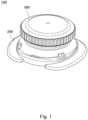
Fig. 1 shows a three-dimensional schematic view of a fastening device according to a first embodiment of the present disclosure. -
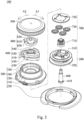
Fig. 2 shows one exploded view of the fastening device of the first embodiment ofFig. 1 . -
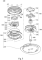
Fig. 3 shows another exploded view of the fastening device of the first embodiment ofFig. 1 . -
Fig. 4 shows one cross-sectional side view of the fastening device of the first embodiment ofFig. 1 . -
Fig. 5 shows another cross-sectional side view of the fastening device of the first embodiment ofFig. 1 . -
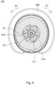
Fig. 6 shows a cross-sectional top view of the fastening device of the first embodiment ofFig. 4 taken along line 6-6. -
Fig. 7 shows a three-dimensional schematic view of a fastening device according to a second embodiment of the present disclosure. -
Fig. 8 shows one exploded view of the fastening device of the second embodiment ofFig. 7 . -
Fig. 9 shows another exploded view of the fastening device of the second embodiment ofFig. 7 . -
Fig. 10 shows one cross-sectional side view of the fastening device of the second embodiment ofFig. 7 . -
Fig. 11 shows another cross-sectional side view of the fastening device of the second embodiment ofFig. 7 . -
Fig. 12 shows a cross-sectional top view of the fastening device of the second embodiment ofFig. 10 taken along line 12-12. -
Fig. 13 shows a three-dimensional schematic view of a fastening device according to a third embodiment of the present disclosure. -
Fig. 14 shows one exploded view of the fastening device of the third embodiment ofFig. 13 . -
Fig. 15 shows another exploded view of the fastening device of the third embodiment ofFig. 13 . -
Fig. 16 shows one cross-sectional side view of the fastening device of the third embodiment ofFig. 13 . -
Fig. 17 shows another cross-sectional side view of the fastening device of the third embodiment ofFig. 13 . -
Fig. 18 shows a cross-sectional top view of the fastening device of the third embodiment ofFig. 16 taken along line 18-18. -
Fig. 19 shows a three-dimensional schematic view of a fastening device according to a fourth embodiment of the present disclosure. -
Fig. 20 shows one exploded view of the fastening device of the fourth embodiment ofFig. 19 . -
Fig. 21 shows another exploded view of the fastening device of the fourth embodiment ofFig. 19 . -
Fig. 22 shows one cross-sectional side view of the fastening device of the fourth embodiment ofFig. 19 . -
Fig. 23 shows another cross-sectional side view of the fastening device of the fourth embodiment ofFig. 19 . -
Fig. 24 shows a cross-sectional top view of the fastening device of the fourth embodiment ofFig. 22 taken along line 24-24. -
Fig. 25 shows a three-dimensional schematic view of a fastening device according to a fifth embodiment of the present disclosure. -
Fig. 26 shows one exploded view of the fastening device of the fifth embodiment ofFig. 25 . -
Fig. 27 shows another exploded view of the fastening device of the fifth embodiment ofFig. 25 . -
Fig. 28 shows one cross-sectional side view of the fastening device of the fifth embodiment ofFig. 25 . -
Fig. 29 shows another cross-sectional side view of the fastening device of the fourth embodiment ofFig. 25 . - The embodiments of the present disclosure will be illustrated with drawings hereinafter. In order to clearly describe the content, many practical details will be mentioned with the description hereinafter. However, it will be understood by the reader that the practical details will not limit the present disclosure. In other words, in some embodiment of the present disclosure, the practical details are not necessary. Additionally, in order to simplify the drawings, some conventional structures and elements will be illustrated in the drawings in a simple way; the repeated elements may be labeled by the same or similar reference numerals.
- In addition, the terms first, second, third, etc. are used herein to describe various elements or components, these elements or components should not be limited by these terms. Consequently, a first element or component discussed below could be termed a second element or component. Moreover, the combinations of the elements, the components, the mechanisms and the modules are not well-known, ordinary or conventional combinations, and whether the combinations can be easily completed by the one skilled in the art cannot be judged based on whether the elements, the components, the mechanisms or the module themselves are well-known, ordinary or conventional.
-
Fig. 1 shows a three-dimensional schematic view of afastening device 100 according to a first embodiment of the present disclosure.Fig. 2 shows one exploded view of thefastening device 100 of the first embodiment ofFig. 1 .Fig. 3 shows another exploded view of thefastening device 100 of the first embodiment ofFig. 1 . Thefastening device 100 includes acase unit 200, aspool 300, an engagingunit 400, aknob 500 and atorque unit 800. - The
case unit 200 includes an inner space. Thespool 300 is received within the inner space and is configured for a lace to be wound thereabout. The engagingunit 400 is located above thespool 300 along an axis I1 (shown inFig. 4 ). Theknob 500 is located above the engagingunit 400 along theaxis 11. Thetorque unit 800 is rotably connected to one of theknob 500 and the engagingunit 400, and thetorque unit 800 selectively transmits a rotating force to thespool 300. As theknob 500 is rotated in a tensioning direction A1, theknob 500 drives the engagingunit 400 to rotate thespool 300 in the tensioning direction A1 for tensioning the lace. As the lace is over tensioned, thespool 300 is not rotated in the tensioning direction A1. - Therefore, as the lace is over tensioned, a user cannot rotate the
spool 300 by theknob 500, and over tightening of the lace can be prevented. Details of thefastening device 100 may be described hereinafter. - The
case unit 200 of thefastening device 100 may include ahousing 210, abase 220, apartition 230, a plurality of engagingteeth 240, acentral hole 250 and a plurality ofinner teeth 260. Thehousing 210 defines the inner space and includes an upper opening and a lower opening, and the upper opening and the lower opening are communicated with the inner space. Thebase 220 is detachably connected to thehousing 210 to close the lower opening by engagement, but the present disclosure is not limited thereto. - The
partition 230 may protrude inward from thehousing 210 to separate the inner space into an upper chamber and a lower chamber. The engagingteeth 240 are located at thehousing 210 and are in the upper chamber, and theinner teeth 260 are located at thehousing 210 and are in the lower chamber. Thecentral hole 250 may penetrate thepartition 230 to allow the upper chamber to be communicated with the lower chamber. Thespool 300 may be received in the lower chamber. - The
spool 300 may include a spool shaft body, anupper ring portion 310, alower ring portion 320, a plurality of pivoting shafts, a spool hole and aflexible clamping portion 330. Theupper ring portion 310 extends radially and outward from an upper end of the spool shaft body, thelower ring portion 320 extends radially and outward from a lower end of the spool shaft body, and a track is formed between theupper ring portion 310 and thelower ring portion 320 for the lace to be wound thereabout. The pivoting shafts are disposed at an upper surface of the spool shaft body. The spool hole penetrates the spool shaft body to form a spool inner surface. Theflexible clamping portion 330 may include two clamping arms extend downward from the spool inner surface to form a clamping space for coupling a connecting unit of thefastening device 100, and the details thereof may be described hereinafter. - The engaging
unit 400 may include anengaging disc 410, threepawl arms 430, three stoppingportions 450 and a plurality of driving teeth 460. Theengaging disc 410 is a hollow circle and includes a central through hole. Each of thepawl arms 430 extends outward from theengaging disc 410 and has a cantilever structure which may be deflected inward as being forced. Each of the stoppingportions 450 extends outward from theengaging disc 410 and corresponds to a distal end of each of thepawl arms 430. As each of thepawl arms 430 is forced to be deflected inward, each of the stoppingportions 450 may stop each of thepawl arms 430, thereby increasing the capability of prohibiting thespool 300 from rotating reversely. The driving teeth 460 may be disposed at a lower end of theengaging disc 410 to come near thespool 300. - The
fastening device 100 may further include atransmission set 700 coupling to the driving teeth 460 of the engagingunit 400 and thespool 300. Precisely, the transmission set 700 may include asun gear 710, a plurality of planet gears 730 and aplate 720. Thesun gear 710 is driven by the driving teeth 460 of the engagingunit 400. Each of the planet gears 730 is pivotally disposed at each of the pivoting shafts of thespool 300 to engage with thesun gear 710 and theinner teeth 260 of thecase unit 200. Theplate 720 is placed above the planet gears 730 to cover the planet gears 730. - As shown in
Fig. 2 , the engagingunit 400 may further include aboss 420 and at least one engagingportion 440 along the axis I1, theboss 420 is integrally connected to theengaging disc 410, and the at least one engagingportion 440 is disposed at theboss 420. In the first embodiment, a number of the at least one engagingportion 440 is three, and each of the engagingportion 440 has a radial groove structure, but the present disclosure is not limited thereto. - The
torque unit 800 may include atorque disc 820, at least onecoupling portion 830 and at least onetorque portion 810. A number of the at least onecoupling portion 830 is three. The threecoupling portions 830 are disposed with intervals at an inner edge of thetorque disc 820, each of thecoupling portions 830 may be engaged with each of the engagingportions 440, and each of thecoupling portions 830 may have a bump structure extending radially and inward. Thecoupling portions 830 and the at least onetorque portion 810 may be staggered along a radial direction. Specially, a number of the at least onetorque portion 810 is also three and the threetorque portions 810 are disposed with intervals at an outer edge of thetorque disc 820. Moreover, one of thetorque portions 810 is located between two of thecoupling portions 830, and each of thetorque portions 810 may have a triangular bump structure and include a forced inclined surface 811 (labeled inFig. 6 ) for increasing the structural stability. - As assembling, the
torque unit 800 may sleeve on theboss 420 of the engagingunit 400, each of thecoupling portions 830 having the bump structure may coordinate with each of the engagingportions 440 having the groove structure, thereby rotably connecting thetorque unit 800 to the engagingunit 400, but the combination method is not limited thereto. In addition, after thetorque unit 800 and the engagingunit 400 are assembled, a deforming space S1 (labeled inFig. 6 ) is formed between at least one portion of thetorque unit 800 and theboss 420. Therefore, as a force born by thetorque unit 800, especially born by each of thetorque portions 810, exceeds a threshold, the at least one portion of thetorque unit 800 is deformed radially. In other words, with that theboss 420 is a triangle, that thetorque disc 820 is a hollow circle, and that the engagingportions 440 are respectively located at three corners of the triangle to correspond to thecoupling portions 830, three deforming spaces S1 may be respectively formed between three side edges of the triangle of theboss 420 and the inner edge of the hollow circle. Portions of the hollow circle corresponding to the side edges of the triangle of theboss 420 may be the portions that may be deformed radially and inward. Hence, with the configuration that each of thetorque portions 810 are respectively located at each of the portions, especially the center position of each of the side edges, each of thetorque portions 810 may be deformed as forced. - The
knob 500 is cap-shaped. Theknob 500 may be selectively coupled to thetorque unit 800 and may include at least one pushingportion 510 corresponding to the at least onetorque portion 810. A number of the at least one pushingportion 510 is three. Theknob 500 may further include atop recess 520 for receiving thetorque unit 800. The three pushingportions 510 are disposed at the side wall of thetop recess 520 with intervals, and each of the pushingportions 510 may correspond to each of thetorque portions 810. Each of the pushingportions 510 may include a pushing inclined surface 511 (labeled inFig. 6 ) to correspond to the forcedinclined surface 811 of each of thetorque portions 810, and each of the pushingportions 510 pushes each of thetorque portions 810 to rotate the engagingunit 400 in the tensioning direction A1. -
Fig. 4 shows one cross-sectional side view of thefastening device 100 of the first embodiment ofFig. 1 .Fig. 5 shows another cross-sectional side view of thefastening device 100 of the first embodiment ofFig. 1 .Fig. 6 shows a cross-sectional top view of thefastening device 100 of the first embodiment ofFig. 4 taken along line 6-6. Thefastening device 100 may further include the connecting unit. One end of the connecting unit is connected to theknob 500, and another end of the connecting unit is connected to thespool 300. The connecting unit may include apositioning post 600 and a screwing member. Thepositioning post 600 includes apositioning protrusion 610. Thepositioning post 600 is inserted upward into thespool 300 and thesun gear 710 and then enters a central post of theknob 500. The screwing member is inserted downward into the central post to fasten with thepositioning post 600. Thepositioning post 600 and theknob 500 are connected in the axis I1. - As shown in
Figs. 4 and6 , theknob 500 is not pulled up, and the engagingunit 400 is positioned at a first position. The pushinginclined surface 511 of each of the pushingportions 510 corresponds the forcedinclined surface 811 of each of thetorque portions 810 of thetorque unit 800, the driving teeth 460 of the engagingunit 400 is engaged with thesun gear 710, and each of thepawl arms 430 is engaged with the engagingteeth 240. As the user holds and rotates theknob 500 in the tensioning direction A1, each of the pushingportions 510 pushes each of thetorque portions 810 to transmit the rotating force of theknob 500 to the engagingunit 400, the distal end of each of thepawl arms 430 is continuously disengaged from the engagingteeth 240, and the engagingunit 400 may drive thespool 300 to rotate in the tensioning direction A1 for tensioning the lace via thetransmission set 700. - As the lace is tensioned, a force will exert on the
spool 300 and try to rotate thespool 300 in a releasing direction A2, and each of thetorque portions 810 will try to push each of the pushingportions 510 toward the releasing direction A2 so as to prevent from moving by each of the pushingportions 510 of theknob 500. Consequently, as the force born by each of thetorque portions 810 exceeds the threshold, the forcedinclined surface 811 thereof slides relative to the pushinginclined surface 511 of each of the pushingportions 510, and each of the forcedinclined surfaces 811 deforms radially and inward to allow each of the pushingportions 510 to cross over each of thetorque portions 810, theknob 500 cannot drive thetorque unit 800, and thespool 300 cannot be driven in the tensioning direction A1 for tensioning the lace. As the user stops exerting the force, the distal end of each of thepawl arms 430 is engaged with the engagingteeth 240 to prohibit thespool 300 from rotating in the releasing direction A2, and the lace cannot be released. - As shown in
Fig. 5 , theknob 500 is pulled upward to release the lace. As theknob 500 is pulled upward, theknob 500 and thepositioning post 600 are moved along the axial axis I1. Thepositioning protrusion 610 of thepositioning post 600 may be moved from a lower side of projections of theflexible clamping portion 330 to an upper side of the projections of theflexible clamping portion 330. Thepositioning post 600 moves the engagingunit 400 upward along the axis I1 to switch from the first position to a second position. At this time, each of thepawl arms 430 of the engagingunit 400 is disengaged from the engagingteeth 240, the engagingunit 400 does not prohibit thespool 300 from rotating in the releasing direction A2, and the lace is released. -
Fig. 7 shows a three-dimensional schematic view of afastening device 100a according to a second embodiment of the present disclosure.Fig. 8 shows one exploded view of thefastening device 100a of the second embodiment ofFig. 7 .Fig. 9 shows another exploded view of thefastening device 100a of the second embodiment ofFig. 7 . The structure of thefastening device 100a of the second embodiment is similar to the structure of thefastening device 100 of the first embodiment and includes aknob 500a, atorque unit 800a, an engagingunit 400a, a transmission set 700a, aspool 300a and acase unit 200a. Only the differences thereof are illustrated hereinafter, and the identical or similar contents will not be repeated. - The
torque unit 800a may include atorque disc 820a, threetorque portions 810a and threecoupling portions 830a. The threecoupling portions 830a are disposed at an upper edge of thetorque disc 820a and are coupled to theknob 500a, thereby rotably connecting thetorque unit 800a and theknob 500a. The threetorque portions 810a may be disposed at an inner edge of thetorque disc 820a. The engagingunit 400a may further include three forcedportions 470a respectively corresponding to the threetorque portions 810a. As a force born by each of thetorque portions 810a exceeds a threshold, each of thetorque portions 810a is deformed to allow each of thetorque portions 810a to move from one side of each of the forcedportions 470a to another side of each of the forcedportions 470a. It is noted that, a number of the forcedportions 470a corresponds to a number of thetorque portions 810a. Therefore, in other embodiments, as a number of the torque portion is at least one, a number of the forced portion is at least one. - Precisely, the
knob 500a may include three engagingholes 530a disposed at an inner top of theknob 500a with intervals. Each of the engagingholes 530a is for each of thecoupling portions 830a to insert therein, thereby assembling and rotably connecting thetorque unit 800a and theknob 500a. - A
boss 420a of the engagingunit 400a may be a hollow circle, and each of the forcedportions 470a may extend from an outer edge of theboss 420a radially and outward. As the engagingunit 400a and thetorque unit 800a are assembled, each of the forcedportions 470a may contact each of thetorque portions 810a. -
Fig. 10 shows one cross-sectional side view of thefastening device 100a of the second embodiment ofFig. 7 .Fig. 11 shows another cross-sectional side view of thefastening device 100a of the second embodiment ofFig. 7 .Fig. 12 shows a cross-sectional top view of thefastening device 100a of the second embodiment ofFig. 10 taken along line 12-12. As shown inFigs. 10 and12 , theknob 500a is not pulled up, and the engagingunit 400a is positioned at a first position. As the user holds and rotates theknob 500a in the tensioning direction A1, thetorque unit 800a is rotated to allow each of thetorque portions 810a to push each of the forcedportions 470a and to transmit a rotating force of theknob 500a to the engagingunit 400a, thereby driving thespool 300a to rotate in the tensioning direction A1 to tension the lace. - As the lace is tensioned, a force will exert on the
spool 300a and try to rotate thespool 300a in the releasing direction A2, and each of the forcedportions 470a will try to push each of thetorque portions 810a toward the releasing direction A2. Consequently, as a force born by each of thetorque portions 810a exceeds a threshold, each of thetorque portions 810a deforms radially and outward. Theknob 500a and thetorque unit 800a rotate relative to the engagingunit 400a, and thespool 300a cannot be driven in the tensioning direction A1 for tensioning the lace. It is noted that, a gap is contained between thetorque disc 820a and an inner annular surface of theknob 500a, and the gap is for thetorque disc 820a to deform radially and outward. Moreover, as shown inFig. 11 , theknob 500a is pulled upward to release the lace, and details thereof will not be repeated. -
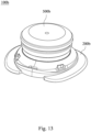
Fig. 13 shows a three-dimensional schematic view of afastening device 100b according to a third embodiment of the present disclosure.Fig. 14 shows one exploded view of thefastening device 100b of the third embodiment ofFig. 13 .Fig. 15 shows another exploded view of thefastening device 100b of the third embodiment ofFig. 13 . The structure of thefastening device 100b of the third embodiment is similar to the structure of thefastening device 100 of the first embodiment and includes aknob 500b, atorque unit 800b, an engagingunit 400b, atransmission set 700b, aspool 300b and acase unit 200b. Only the differences thereof are illustrated hereinafter, and the identical or similar contents will not be repeated. - The
torque unit 800b and the engagingunit 400b are rotably connected. Thetorque unit 800b includes atorque disc 820b and threetorque portions 810b, each of thetorque portions 810b extends along a circumferential direction of thetorque unit 800b, especially extending along the circumferential direction of thetorque disc 820b. Theknob 500b includes three pushingportions 510b respectively pushing the distal ends of the threetorque portions 810b to rotate thespool 300b in the tensioning direction A1. As a force born by each of thetorque portions 810b exceeds a threshold, a friction force between afriction surface 812b of each of thetorque portions 810b and thecase unit 200b prohibits theknob 500b from rotating thespool 300b. - To be more specific, the
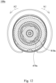
torque unit 800b includes three connecting portions (not labeled), the three connecting portions are disposed at an outer edge of thetorque disc 820b with intervals, and each of the connecting portions extends radially and outward. Each of thetorque portions 810b extends integrally along the circumference direction from one side surface of each of the connecting portions, and a distal end of each of thetorque portions 810b includes anend plane 813b (labeled inFig. 18 ). Each of the pushingportions 510b of theknob 500b may include a pushingsurface 512b (labeled inFig. 18 ) abutted against each of theend plane 813b, and as theknob 500b is rotated in the tensioning direction A1, each of thetorque portions 810b is pushed so as to allow thetorque unit 800b to rotate in the tensioning direction A1. - The
torque unit 800b may further include threeengaging grooves 840b depressedly disposed at thetorque disc 820b. The engagingunit 400b may include three engagingprotrusions 480b, and the engagingprotrusions 480b are respectively engaged with the engaginggrooves 840b, thereby rotably connecting thetorque unit 800b and the engagingunit 400b. - The
housing 210b of thecase unit 200b may include anupper portion 211b. Theupper portion 211b is located at an upper side of engagingteeth 240b and is toothless. After thetorque unit 800b is assembled in thecase unit 200b, thefriction surface 812b of each of thetorque portions 810b faces toward theupper portion 211b. -
Fig. 16 shows one cross-sectional side view of thefastening device 100b of the third embodiment ofFig. 13 .Fig. 17 shows another cross-sectional side view of thefastening device 100b of the third embodiment ofFig. 13 .Fig. 18 shows a cross-sectional top view of thefastening device 100b of the third embodiment ofFig. 16 taken along line 18-18. As shown inFigs. 16 and18 , theknob 500b is not pulled up, and the engagingunit 400b is positioned at a first position. As the user holds and rotates theknob 500b in the tensioning direction A1, each of the pushingportions 510b may push each of thetorque portions 810b to rotate thetorque unit 800b for transmitting a rotating force of theknob 500b to the engagingunit 400b, thereby driving thespool 300b to rotate in the tensioning direction A1 to tension the lace. - As the lace is tensioned, a force will exert on the
spool 300b and try to rotate thespool 300b in the releasing direction A2, which causes difficulty in rotating the engagingunit 400b in the tensioning direction A1. Therefore, as each of the pushingportions 510b pushes each of thetorque portions 810b, each of thetorque portions 810b will be bended so as to allow thefriction surface 812b thereof contacts an inner wall of theupper portion 211b of thehousing 210b to generate the friction force. As a force born by each of thetorque portions 810b exceeds a threshold, a bending curve of each of thetorque portions 810b becomes larger, which may lead to a larger contacting surface between each of the friction surfaces 812b and theupper portion 211b. As a result, the friction force is increased, theknob 500b cannot drive thetorque unit 800b to rotate in the tensioning direction A1, and thespool 300b cannot be driven in the tensioning direction A1 for tensioning the lace. Moreover, as shown inFig. 17 , theknob 500b is pulled upward to release the lace, and details thereof will not be repeated. -
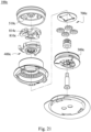
Fig. 19 shows a three-dimensional schematic view of afastening device 100c according to a fourth embodiment of the present disclosure.Fig. 20 shows one exploded view of thefastening device 100c of the fourth embodiment ofFig. 19 .Fig. 21 shows another exploded view of thefastening device 100c of the fourth embodiment ofFig. 19 . The structure of thefastening device 100c of the forth embodiment is similar to the structure of thefastening device 100b of the third embodiment and includes aknob 500c, atorque unit 800c, an engagingunit 400c, atransmission set 700c, aspool 300c and acase unit 200c. Only the differences thereof are illustrated hereinafter, and the identical or similar contents will not be repeated. - The
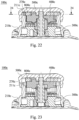
torque unit 800c and the engagingunit 400c are rotably connected. Thetorque unit 800c includes atorque disc 820c and threetorque portions 810c, and each of thetorque portions 810c extends along a circumferential direction of thetorque unit 800c, especially extending along the circumferential direction of thetorque disc 820c. Each of thetorque portions 810c may include atorque tooth 814c. Theknob 500c includes three pushingportions 510c respectively pushing the threetorque portions 810c to rotate thespool 300c in the tensioning direction A1. Thecase unit 200c may include a plurality ofdepressions 270c. As a force born by each of thetorque portions 810c exceeds a threshold, each of thetorque portions 810c is bended to allow thetorque tooth 814c thereof to engage with one of thedepressions 270c, thereby prohibiting theknob 500c from rotating thespool 300c. - Precisely, the
housing 210c of thecase unit 200c may include anupper portion 211c. Theupper portion 211c is located an upper side of engagingteeth 240c, and thedepressions 270c are located at theupper portion 211c. Thetorque tooth 814c of each of thetorque portions 810c may have an external toothed structure and is near a distal end of each of thetorque portions 810c. After thetorque unit 800c is assembled in thecase unit 200c, thetorque tooth 814c of each of thetorque portions 810c faces toward thedepressions 270c. -
Fig. 22 shows one cross-sectional side view of thefastening device 100c of the fourth embodiment ofFig. 19 .Fig. 23 shows another cross-sectional side view of thefastening device 100c of the fourth embodiment ofFig. 19 .Fig. 24 shows a cross-sectional top view of thefastening device 100c of the fourth embodiment ofFig. 22 taken along line 24-24. As shown inFigs. 22 and24 , theknob 500c is not pulled up, and the engagingunit 400c is positioned at a first position. As the user holds and rotates theknob 500c in the tensioning direction A1, each of the pushingportions 510c may push each of thetorque portions 810c to rotate totorque unit 800c for transmitting a rotating force of theknob 500c to the engagingunit 400c owing to that thetorque tooth 814c of each of thetorque portions 810c does not engage with thedepressions 270c, thereby driving thespool 300c to rotate in the tensioning direction A1 to tension the lace. - As the lace is tensioned, a force will exert on the
spool 300c and try to rotate thespool 300c in the releasing direction A2, which causes difficulty in rotating the engagingunit 400c in the tensioning direction A1. Therefore, as each of the pushingportions 510c pushes each of thetorque portions 810c, each of thetorque portions 810c will be bended, and thetorque tooth 814c of each of thetorque portions 810c starts to engage with thedepressions 270c. As a force born by each of thetorque portions 810c exceeds a threshold, a bending curve of each of thetorque portions 810c becomes larger, which may lead to a complete engagement between thetorque tooth 814c of each of thetorque portions 810c and thedepressions 270c. As a result, theknob 500c cannot drive thetorque unit 800c to rotate in the tensioning direction A1, and thespool 300c cannot be driven in the tensioning direction A1 for tensioning the lace. Moreover, as shown inFig. 23 , theknob 500c is pulled upward to release the lace, and details thereof will not be repeated. -
Fig. 25 shows a three-dimensional schematic view of afastening device 100d according to a fifth embodiment of the present disclosure.Fig. 26 shows one exploded view of thefastening device 100d of the fifth embodiment ofFig. 25 .Fig. 27 shows another exploded view of thefastening device 100d of the fifth embodiment ofFig. 25 . The structure of thefastening device 100d of the fifth embodiment is similar to the structure of thefastening device 100b of the third embodiment and includes aknob 500d, an engagingunit 400d, atransmission set 700d, aspool 300d and acase unit 200d, and the engagingunit 400d includes at least onepawl arm 430d. Only the differences thereof are illustrated hereinafter, and the identical or similar contents will not be repeated. - The
fastening device 100d may include at least onetorque portion 490d, and the at least onetorque portion 490d is rotably connected to the at least onepawl arm 430d. Precisely, a number of the at least onetorque portion 490d is three, and a number of the at least onepawl arm 430d is three. The engagingunit 400d may include anengaging disc 410d, the threetorque portions 490d and the threepawl arms 430d. The threetorque portions 490d and the threepawl arms 430d are disposed at theengaging disc 410d with intervals. In other words, in the fifth embodiment, no independent torque disc is included for placing thetorque portions 490d, and thetorque portions 490d are disposed at theengaging disc 410d. As theengaging disc 410d is located in the upper chamber, each of thetorque portions 490d may contact apartition 230d to generate a friction force. -
Fig. 28 shows one cross-sectional side view of thefastening device 100d of the fifth embodiment ofFig. 25 .Fig. 29 shows another cross-sectional side view of thefastening device 100d of the fourth embodiment ofFig. 25 . As shown inFig. 28 , theknob 500d is not pulled up, and the engagingunit 400d is positioned at a first position. As the user holds and rotates theknob 500d in the tensioning direction A1, in a status that the tension of the lace is small, the friction between each of thetorque portions 490d and thepartition 230d does not affect rotation of thespool 300d owing to the small friction force therebetween. As a force born by each of thetorque portions 490d exceeds a threshold, a bending curve of each of thetorque portions 490d becomes larger, which may lead to a larger friction force between each of thetorque portions 490d and thepartition 230d. As a result, theknob 500d cannot drive the engagingunit 400d to rotate in the tensioning direction A1, and thespool 300d cannot be driven in the tensioning direction A1 for tensioning the lace, thereby preventing over tension of the lace. Moreover, as shown inFig. 29 , theknob 500d is pulled upward to release the lace, and details thereof will not be repeated. - Based on the above embodiments, with the configuration of the torque portion, as the lace is over tensioned, the knob may rotate relative to the spool in the tensioning direction, or the knob cannot be rotated in the tensioning direction, and a goal of prohibiting the spool from rotating in the tensioning direction is achieved. Moreover, the torque portion may be disposed at an independent torque disc to form an independent torque unit, or the torque portion may be disposed at the engaging disc while no independent torque unit is included, but the goal that the spool cannot rotate in the tensioning direction while the lace is over tensioned has to be achieved. In addition, a friction force may be generated between the torque portion and any part of the case unit or any part of the knob to prohibit rotation of the knob in the tensioning direction, and the present disclosure is not limited thereto.
Claims (11)
- A fastening device (100, 100a, 100b, 100c, 100d), characterized in comprising:a case unit (200, 200a, 200b, 200c, 200d) comprising an inner space and a plurality of engaging teeth (240, 240b, 240c);a spool (300, 300a, 300b, 300c, 300d) received within the inner space and configured for a lace to be wound thereabout;a knob (500, 500a, 500b, 500c, 500d) covering the case unit (200, 200a, 200b, 200c, 200d);at least one pawl arm (430, 430d) received in the inner space and corresponding to at least one of the engaging teeth (240, 240b, 240c); andat least one torque portion (810, 810a, 810b, 810c, 490d) received in the inner space and being rotably connected to one of the knob (500, 500a, 500b, 500c, 500d) and the at least one pawl arm (430, 430d);wherein as a rotation of the knob (500, 500a, 500b, 500c, 500d) in a tensioning direction (A1) causes the at least one pawl arm (430, 430d) to rotate, the spool (300, 300a, 300b, 300c, 300d) is rotated in the tensioning direction (A1) to tension the lace, and as the lace is over tensioned, the at least one torque portion (810, 810a, 810b, 810c, 490d) prohibits the spool (300, 300a, 300b, 300c, 300d) from rotating in the tensioning direction (A1).
- The fastening device (100, 100a, 100b, 100c, 100d) of claim 1, further comprising a connecting unit, wherein one end of the connecting unit is connected to the knob (500, 500a, 500b, 500c, 500d), and another end of the connecting unit is coupled to the spool (300, 300a, 300b, 300c, 300d).
- The fastening device (100, 100a, 100b, 100c, 100d) of any of claims 1 to 2, wherein the connecting unit comprises a positioning post (600), and the spool (300, 300a, 300b, 300c, 300d) comprises a flexible clamping portion (330) coupled to the positioning post (600).
- The fastening device (100, 100a, 100b, 100c, 100d) of any of claims 1 to 3, further comprising a torque disc (820, 820a, 820b, 820c) and at least one coupling portion (830, 830a), wherein the at least one coupling portion (830, 830a) and the at least one torque portion (810, 810a, 810b, 810c, 490d) are disposed at the torque disc (820, 820a, 820b, 820c) with an interval.
- The fastening device (100, 100a, 100b, 100c, 100d) of any of claims 1 to 4, further comprising an engaging disc (410, 410d), a boss (420, 420a) and at least one engaging portion (440), wherein the at least one coupling portion (830, 830a) is disposed at an inner edge of the torque disc (820, 820a, 820b, 820c), the at least one torque portion (810, 810a, 810b, 810c, 490d) is located at an outer edge of the torque disc (820, 820a, 820b, 820c), the at least one pawl arm (430, 430d) is disposed at the engaging disc (410, 410d), the boss (420, 420a) is integrally connected to the engaging disc (410, 410d) along an axis (11), the at least one engaging portion (440) is disposed at the boss (420, 420a) and correspondingly engaged with the at least one coupling portion (830, 830a) to allow the at least one torque portion (810, 810a, 810b, 810c, 490d) to be rotably connected to the at least one pawl arm (430, 430d), and at least one deforming space (S1) is formed between the inner edge of the torque disc (820, 820a, 820b, 820c) and at least one side edge of the boss (420, 420a), thereby allowing the at least one torque portion (810, 810a, 810b, 810c, 490d) to be deformed inward.
- The fastening device (100, 100a, 100b, 100c, 100d) of any of claims 1 to 5, wherein the knob (500, 500a, 500b, 500c, 500d) comprises at least one pushing portion (510, 510b, 510c) corresponding to the at least one torque portion (810, 810a, 810b, 810c, 490d), and as a force born by the at least one torque portion (810, 810a, 810b, 810c, 490d) exceeds a threshold, the at least one torque portion (810, 810a, 810b, 810c, 490d) is deformed to allow the at least one pushing portion (510, 510b, 510c) to move from one side of the at least one torque portion (810, 810a, 810b, 810c, 490d) to another side of the at least one torque portion (810, 810a, 810b, 810c, 490d).
- The fastening device (100, 100a, 100b, 100c, 100d) of any of claims 1 to 6, further comprising an engaging disc (410, 410d) and at least one forced portion (470a), wherein the at least one forced portion (470a) is disposed at the engaging disc (410, 410d) and corresponds to the at least one torque portion (810, 810a, 810b, 810c, 490d), the at least one coupling portion (830, 830a) is disposed at an upper edge of the torque disc (820, 820a, 820b, 820c) and coupled to the knob (500, 500a, 500b, 500c, 500d) to allow the torque disc (820, 820a, 820b, 820c) to be rotably connected to the knob (500, 500a, 500b, 500c, 500d), the at least one torque portion (810, 810a, 810b, 810c, 490d) is disposed at an inner edge of the torque disc (820, 820a, 820b, 820c), and as a forced born by the at least one torque portion (810, 810a, 810b, 810c, 490d) exceeds a threshold, the at least one torque portion (810, 810a, 810b, 810c, 490d) is deformed to allow the at least one torque portion (810, 810a, 810b, 810c, 490d) to move from one side of the at least one forced portion (470a) to another side of the at least one forced portion (470a).
- The fastening device (100, 100a, 100b, 100c, 100d) of any of claims 1 to 7, wherein the at least one torque portion (810, 810a, 810b, 810c, 490d) and the at least one pawl arm (430, 430d) are rotably connected, the knob (500, 500a, 500b, 500c, 500d) comprises at least one pushing portion (510, 510b, 510c) pushing the at least one torque portion (810, 810a, 810b, 810c, 490d) to rotate the spool (300, 300a, 300b, 300c, 300d) in the tensioning direction (A1), and as a forced born by the at least one torque portion (810, 810a, 810b, 810c, 490d) exceeds a threshold, a friction force between a friction surface (812b) of the at least one torque portion (810, 810a, 810b, 810c, 490d) and the case unit (200, 200a, 200b, 200c, 200d) prohibits the knob (500, 500a, 500b, 500c, 500d) from rotating the spool (300, 300a, 300b, 300c, 300d).
- The fastening device (100, 100a, 100b, 100c, 100d) of any of claims 1 to 8, wherein the at least one torque portion (810, 810a, 810b, 810c, 490d) and the at least one pawl arm (430, 430d) are rotably connected, the at least one torque portion (810, 810a, 810b, 810c, 490d) comprises a torque tooth (814c), the knob (500, 500a, 500b, 500c, 500d) comprises at least one pushing portion (510, 510b, 510c) pushing the at least one torque portion (810, 810a, 810b, 810c, 490d) to rotate the spool (300, 300a, 300b, 300c, 300d) in the tensioning direction (A1), the case unit (200, 200a, 200b, 200c, 200d) comprises a plurality of depressions (270c), and as a forced born by the at least one torque portion (810, 810a, 810b, 810c, 490d) exceeds a threshold, the at least one torque portion (810, 810a, 810b, 810c, 490d) is bended so as to allow the torque tooth (814c) to be engaged with one of the depressions (270c) to prohibit the knob (500, 500a, 500b, 500c, 500d) from rotating the spool (300, 300a, 300b, 300c, 300d).
- The fastening device (100, 100a, 100b, 100c, 100d) of any of claims 1 to 9, further comprising an engaging disc (410, 410d), wherein the at least one torque portion (810, 810a, 810b, 810c, 490d) and the at least one pawl arm (430, 430d) are disposed at the engaging disc (410, 410d) with an interval, the case unit (200, 200a, 200b, 200c, 200d) further comprises a housing (210, 210b, 210c) and a partition (230, 230d), the partition (230, 230d) protrudes inward from the housing (210, 210b, 210c) to separate the inner space into an upper chamber and a lower chamber, the engaging teeth (240, 240b, 240c) are located at the housing (210, 210b, 210c) and are in the upper chamber, and the at least one torque portion (810, 810a, 810b, 810c, 490d) contacts the partition (230, 230d) to generate a friction force.
- The fastening device (100, 100a, 100b, 100c, 100d) of any of claims 1 to 10, wherein the at least one torque portion (810, 810a, 810b, 810c, 490d) comprises a forced inclined surface (811), and the at least one pushing portion (510, 510b, 510c) comprises a pushing inclined surface (511) corresponding to the forced inclined surface (811) of the at least one torque portion (810, 810a, 810b, 810c, 490d).
Applications Claiming Priority (2)
| Application Number | Priority Date | Filing Date | Title |
|---|---|---|---|
| US202363521943P | 2023-06-20 | 2023-06-20 | |
| TW113113590A TW202500896A (en) | 2023-06-20 | 2024-04-11 | Fastening device |
Publications (2)
| Publication Number | Publication Date |
|---|---|
| EP4480339A1 true EP4480339A1 (en) | 2024-12-25 |
| EP4480339B1 EP4480339B1 (en) | 2026-01-28 |
Family
ID=91617105
Family Applications (1)
| Application Number | Title | Priority Date | Filing Date |
|---|---|---|---|
| EP24183219.5A Active EP4480339B1 (en) | 2023-06-20 | 2024-06-19 | Fastening device |
Country Status (8)
| Country | Link |
|---|---|
| US (1) | US20240423327A1 (en) |
| EP (1) | EP4480339B1 (en) |
| JP (1) | JP2025001653A (en) |
| KR (1) | KR20240177728A (en) |
| CN (1) | CN119160719A (en) |
| DK (1) | DK4480339T3 (en) |
| ES (1) | ES3065491T3 (en) |
| FI (1) | FI4480339T3 (en) |
Families Citing this family (2)
| Publication number | Priority date | Publication date | Assignee | Title |
|---|---|---|---|---|
| US20240375910A1 (en) * | 2023-01-12 | 2024-11-14 | Boa Technology, Inc. | Reel based closure device |
| CN116965617B (en) * | 2023-07-13 | 2026-07-14 | 泉州振科技术服务有限公司 | Prevent breaking off with fingers rope thing receive and releases device and shoes off with fingers and thumb |
Citations (2)
| Publication number | Priority date | Publication date | Assignee | Title |
|---|---|---|---|---|
| EP4136999A1 (en) * | 2021-08-18 | 2023-02-22 | Chin-Chu Chen | Fastening device |
| CN116195807A (en) * | 2022-12-05 | 2023-06-02 | 东莞市壹创信息科技有限公司 | Escapement Rotary Control Clutch |
Family Cites Families (5)
| Publication number | Priority date | Publication date | Assignee | Title |
|---|---|---|---|---|
| KR101249420B1 (en) * | 2012-12-17 | 2013-04-03 | 주식회사 신경 | Apparatus for fastening wire |
| WO2015003079A1 (en) * | 2013-07-02 | 2015-01-08 | Boa Technology Inc. | Tension limiting mechanisms for closure devices and methods therefor |
| US11607014B2 (en) * | 2016-11-11 | 2023-03-21 | Chin-Chu Chen | Fastening device and lace assembling method |
| US10633218B2 (en) * | 2018-09-13 | 2020-04-28 | Yu-Chien WANG | Reel device |
| EP4103009A4 (en) * | 2020-02-14 | 2024-03-13 | Shift Holding, LLC | SHIFT DRUM AND ASSOCIATED METHODS |
-
2024
- 2024-05-16 CN CN202410611425.XA patent/CN119160719A/en active Pending
- 2024-06-10 US US18/739,296 patent/US20240423327A1/en active Pending
- 2024-06-17 JP JP2024097578A patent/JP2025001653A/en active Pending
- 2024-06-19 FI FIEP24183219.5T patent/FI4480339T3/en active
- 2024-06-19 DK DK24183219.5T patent/DK4480339T3/en active
- 2024-06-19 EP EP24183219.5A patent/EP4480339B1/en active Active
- 2024-06-19 ES ES24183219T patent/ES3065491T3/en active Active
- 2024-06-19 KR KR1020240079786A patent/KR20240177728A/en active Pending
Patent Citations (2)
| Publication number | Priority date | Publication date | Assignee | Title |
|---|---|---|---|---|
| EP4136999A1 (en) * | 2021-08-18 | 2023-02-22 | Chin-Chu Chen | Fastening device |
| CN116195807A (en) * | 2022-12-05 | 2023-06-02 | 东莞市壹创信息科技有限公司 | Escapement Rotary Control Clutch |
Also Published As
| Publication number | Publication date |
|---|---|
| KR20240177728A (en) | 2024-12-27 |
| FI4480339T3 (en) | 2026-03-13 |
| CN119160719A (en) | 2024-12-20 |
| EP4480339B1 (en) | 2026-01-28 |
| ES3065491T3 (en) | 2026-05-06 |
| DK4480339T3 (en) | 2026-03-02 |
| JP2025001653A (en) | 2025-01-08 |
| US20240423327A1 (en) | 2024-12-26 |
Similar Documents
| Publication | Publication Date | Title |
|---|---|---|
| EP4480339B1 (en) | Fastening device | |
| US11607014B2 (en) | Fastening device and lace assembling method | |
| EP4321050A1 (en) | Fastening device | |
| KR102576708B1 (en) | fastening device | |
| US12419390B2 (en) | Fastening device | |
| US20250024916A1 (en) | Fastening device | |
| TWI694216B (en) | Fastening device | |
| EP3875414A1 (en) | Fastening device | |
| KR102146621B1 (en) | Fastening device and assembly method of race of fastening device | |
| US12207706B2 (en) | Fastening device | |
| US20240035546A1 (en) | Fastening device | |
| CN111846339B (en) | Fastening device | |
| TWM623553U (en) | Fastening device | |
| US11849809B1 (en) | Cord tightening and loosening device, shoe, glove, medical protective equipment and storage device | |
| EP4136999A1 (en) | Fastening device | |
| TW202500896A (en) | Fastening device | |
| CN113662329B (en) | Rotary push-pull automatic shoe buckle | |
| TW202406825A (en) | Fastening device | |
| CN115103611A (en) | Fastening device and tie line assembly method | |
| CN218044023U (en) | shoelace fastening device | |
| JPS6336306Y2 (en) | ||
| CN119683418A (en) | Fastening device |
Legal Events
| Date | Code | Title | Description |
|---|---|---|---|
| PUAI | Public reference made under article 153(3) epc to a published international application that has entered the european phase |
Free format text: ORIGINAL CODE: 0009012 |
|
| STAA | Information on the status of an ep patent application or granted ep patent |
Free format text: STATUS: THE APPLICATION HAS BEEN PUBLISHED |
|
| AK | Designated contracting states |
Kind code of ref document: A1 Designated state(s): AL AT BE BG CH CY CZ DE DK EE ES FI FR GB GR HR HU IE IS IT LI LT LU LV MC ME MK MT NL NO PL PT RO RS SE SI SK SM TR |
|
| STAA | Information on the status of an ep patent application or granted ep patent |
Free format text: STATUS: REQUEST FOR EXAMINATION WAS MADE |
|
| 17P | Request for examination filed |
Effective date: 20250609 |
|
| GRAP | Despatch of communication of intention to grant a patent |
Free format text: ORIGINAL CODE: EPIDOSNIGR1 |
|
| STAA | Information on the status of an ep patent application or granted ep patent |
Free format text: STATUS: GRANT OF PATENT IS INTENDED |
|
| INTG | Intention to grant announced |
Effective date: 20250919 |
|
| GRAS | Grant fee paid |
Free format text: ORIGINAL CODE: EPIDOSNIGR3 |
|
| GRAA | (expected) grant |
Free format text: ORIGINAL CODE: 0009210 |
|
| STAA | Information on the status of an ep patent application or granted ep patent |
Free format text: STATUS: THE PATENT HAS BEEN GRANTED |
|
| AK | Designated contracting states |
Kind code of ref document: B1 Designated state(s): AL AT BE BG CH CY CZ DE DK EE ES FI FR GB GR HR HU IE IS IT LI LT LU LV MC ME MK MT NL NO PL PT RO RS SE SI SK SM TR |
|
| REG | Reference to a national code |
Ref country code: CH Ref legal event code: F10 Free format text: ST27 STATUS EVENT CODE: U-0-0-F10-F00 (AS PROVIDED BY THE NATIONAL OFFICE) Effective date: 20260128 Ref country code: GB Ref legal event code: FG4D |
|
| REG | Reference to a national code |
Ref country code: DE Ref legal event code: R096 Ref document number: 602024002272 Country of ref document: DE |
|
| REG | Reference to a national code |
Ref country code: IE Ref legal event code: FG4D |
|
| REG | Reference to a national code |
Ref country code: DK Ref legal event code: T3 Effective date: 20260227 |
|
| REG | Reference to a national code |
Ref country code: CH Ref legal event code: R17 Free format text: ST27 STATUS EVENT CODE: U-0-0-R10-R17 (AS PROVIDED BY THE NATIONAL OFFICE) Effective date: 20260312 |
|
| REG | Reference to a national code |
Ref country code: FI Ref legal event code: FGE |
|
| REG | Reference to a national code |
Ref country code: NL Ref legal event code: FP |
|
| REG | Reference to a national code |
Ref country code: ES Ref legal event code: FG2A Ref document number: 3065491 Country of ref document: ES Kind code of ref document: T3 Effective date: 20260506 |
|
| PG25 | Lapsed in a contracting state [announced via postgrant information from national office to epo] |
Ref country code: RS Free format text: LAPSE BECAUSE OF FAILURE TO SUBMIT A TRANSLATION OF THE DESCRIPTION OR TO PAY THE FEE WITHIN THE PRESCRIBED TIME-LIMIT Effective date: 20260428 |
|
| PG25 | Lapsed in a contracting state [announced via postgrant information from national office to epo] |
Ref country code: PL Free format text: LAPSE BECAUSE OF FAILURE TO SUBMIT A TRANSLATION OF THE DESCRIPTION OR TO PAY THE FEE WITHIN THE PRESCRIBED TIME-LIMIT Effective date: 20260128 |
|
| PGFP | Annual fee paid to national office [announced via postgrant information from national office to epo] |
Ref country code: DK Payment date: 20260611 Year of fee payment: 3 |
|
| PG25 | Lapsed in a contracting state [announced via postgrant information from national office to epo] |
Ref country code: GR Free format text: LAPSE BECAUSE OF FAILURE TO SUBMIT A TRANSLATION OF THE DESCRIPTION OR TO PAY THE FEE WITHIN THE PRESCRIBED TIME-LIMIT Effective date: 20260429 |
|
| REG | Reference to a national code |
Ref country code: LT Ref legal event code: MG9D |
|
| PG25 | Lapsed in a contracting state [announced via postgrant information from national office to epo] |
Ref country code: LT Free format text: LAPSE BECAUSE OF FAILURE TO SUBMIT A TRANSLATION OF THE DESCRIPTION OR TO PAY THE FEE WITHIN THE PRESCRIBED TIME-LIMIT Effective date: 20260128 |
|
| PGFP | Annual fee paid to national office [announced via postgrant information from national office to epo] |
Ref country code: DE Payment date: 20260609 Year of fee payment: 3 |
|
| PGFP | Annual fee paid to national office [announced via postgrant information from national office to epo] |
Ref country code: NO Payment date: 20260630 Year of fee payment: 3 |
|
| PG25 | Lapsed in a contracting state [announced via postgrant information from national office to epo] |
Ref country code: SE Free format text: LAPSE BECAUSE OF FAILURE TO SUBMIT A TRANSLATION OF THE DESCRIPTION OR TO PAY THE FEE WITHIN THE PRESCRIBED TIME-LIMIT Effective date: 20260128 |
|
| PGFP | Annual fee paid to national office [announced via postgrant information from national office to epo] |
Ref country code: AT Payment date: 20260714 Year of fee payment: 3 Ref country code: FI Payment date: 20260623 Year of fee payment: 3 |
|
| PG25 | Lapsed in a contracting state [announced via postgrant information from national office to epo] |
Ref country code: HR Free format text: LAPSE BECAUSE OF FAILURE TO SUBMIT A TRANSLATION OF THE DESCRIPTION OR TO PAY THE FEE WITHIN THE PRESCRIBED TIME-LIMIT Effective date: 20260128 |
|
| PG25 | Lapsed in a contracting state [announced via postgrant information from national office to epo] |
Ref country code: PT Free format text: LAPSE BECAUSE OF FAILURE TO SUBMIT A TRANSLATION OF THE DESCRIPTION OR TO PAY THE FEE WITHIN THE PRESCRIBED TIME-LIMIT Effective date: 20260528 Ref country code: IS Free format text: LAPSE BECAUSE OF FAILURE TO SUBMIT A TRANSLATION OF THE DESCRIPTION OR TO PAY THE FEE WITHIN THE PRESCRIBED TIME-LIMIT Effective date: 20260528 |
|
| PGFP | Annual fee paid to national office [announced via postgrant information from national office to epo] |
Ref country code: CZ Payment date: 20260612 Year of fee payment: 3 |
|
| PGFP | Annual fee paid to national office [announced via postgrant information from national office to epo] |
Ref country code: FR Payment date: 20260629 Year of fee payment: 3 |
|
| PG25 | Lapsed in a contracting state [announced via postgrant information from national office to epo] |
Ref country code: LV Free format text: LAPSE BECAUSE OF FAILURE TO SUBMIT A TRANSLATION OF THE DESCRIPTION OR TO PAY THE FEE WITHIN THE PRESCRIBED TIME-LIMIT Effective date: 20260128 |
|
| PG25 | Lapsed in a contracting state [announced via postgrant information from national office to epo] |
Ref country code: BG Free format text: LAPSE BECAUSE OF FAILURE TO SUBMIT A TRANSLATION OF THE DESCRIPTION OR TO PAY THE FEE WITHIN THE PRESCRIBED TIME-LIMIT Effective date: 20260128 |