EP4478957B1 - Monitoring video generation method and monitoring video generation system - Google Patents
Monitoring video generation method and monitoring video generation system Download PDFInfo
- Publication number
- EP4478957B1 EP4478957B1 EP23765160.9A EP23765160A EP4478957B1 EP 4478957 B1 EP4478957 B1 EP 4478957B1 EP 23765160 A EP23765160 A EP 23765160A EP 4478957 B1 EP4478957 B1 EP 4478957B1
- Authority
- EP
- European Patent Office
- Prior art keywords
- bounding box
- keyframe
- monitoring video
- monitored target
- frame
- Prior art date
- Legal status (The legal status is an assumption and is not a legal conclusion. Google has not performed a legal analysis and makes no representation as to the accuracy of the status listed.)
- Active
Links
Images

Classifications
-
- H—ELECTRICITY
- H04—ELECTRIC COMMUNICATION TECHNIQUE
- H04N—PICTORIAL COMMUNICATION, e.g. TELEVISION
- H04N7/00—Television systems
- H04N7/18—Closed-circuit television [CCTV] systems, i.e. systems in which the video signal is not broadcast
-
- H—ELECTRICITY
- H04—ELECTRIC COMMUNICATION TECHNIQUE
- H04N—PICTORIAL COMMUNICATION, e.g. TELEVISION
- H04N7/00—Television systems
- H04N7/18—Closed-circuit television [CCTV] systems, i.e. systems in which the video signal is not broadcast
- H04N7/183—Closed-circuit television [CCTV] systems, i.e. systems in which the video signal is not broadcast for receiving images from a single remote source
-
- A—HUMAN NECESSITIES
- A61—MEDICAL OR VETERINARY SCIENCE; HYGIENE
- A61B—DIAGNOSIS; SURGERY; IDENTIFICATION
- A61B6/00—Apparatus or devices for radiation diagnosis; Apparatus or devices for radiation diagnosis combined with radiation therapy equipment
- A61B6/46—Arrangements for interfacing with the operator or the patient
- A61B6/461—Displaying means of special interest
- A61B6/465—Displaying means of special interest adapted to display user selection data, e.g. graphical user interface, icons or menus
-
- A—HUMAN NECESSITIES
- A61—MEDICAL OR VETERINARY SCIENCE; HYGIENE
- A61B—DIAGNOSIS; SURGERY; IDENTIFICATION
- A61B5/00—Measuring for diagnostic purposes; Identification of persons
- A61B5/0059—Measuring for diagnostic purposes; Identification of persons using light, e.g. diagnosis by transillumination, diascopy, fluorescence
- A61B5/0077—Devices for viewing the surface of the body, e.g. camera, magnifying lens
-
- A—HUMAN NECESSITIES
- A61—MEDICAL OR VETERINARY SCIENCE; HYGIENE
- A61B—DIAGNOSIS; SURGERY; IDENTIFICATION
- A61B5/00—Measuring for diagnostic purposes; Identification of persons
- A61B5/05—Detecting, measuring or recording for diagnosis by means of electric currents or magnetic fields; Measuring using microwaves or radio waves
- A61B5/055—Detecting, measuring or recording for diagnosis by means of electric currents or magnetic fields; Measuring using microwaves or radio waves involving electronic [EMR] or nuclear [NMR] magnetic resonance, e.g. magnetic resonance imaging
-
- A—HUMAN NECESSITIES
- A61—MEDICAL OR VETERINARY SCIENCE; HYGIENE
- A61B—DIAGNOSIS; SURGERY; IDENTIFICATION
- A61B5/00—Measuring for diagnostic purposes; Identification of persons
- A61B5/103—Measuring devices for testing the shape, pattern, colour, size or movement of the body or parts thereof, for diagnostic purposes
- A61B5/11—Measuring movement of the entire body or parts thereof, e.g. head or hand tremor or mobility of a limb
- A61B5/1113—Local tracking of patients, e.g. in a hospital or private home
- A61B5/1114—Tracking parts of the body
-
- A—HUMAN NECESSITIES
- A61—MEDICAL OR VETERINARY SCIENCE; HYGIENE
- A61B—DIAGNOSIS; SURGERY; IDENTIFICATION
- A61B5/00—Measuring for diagnostic purposes; Identification of persons
- A61B5/103—Measuring devices for testing the shape, pattern, colour, size or movement of the body or parts thereof, for diagnostic purposes
- A61B5/11—Measuring movement of the entire body or parts thereof, e.g. head or hand tremor or mobility of a limb
- A61B5/1126—Measuring movement of the entire body or parts thereof, e.g. head or hand tremor or mobility of a limb using a particular sensing technique
- A61B5/1128—Measuring movement of the entire body or parts thereof, e.g. head or hand tremor or mobility of a limb using a particular sensing technique using image analysis
-
- A—HUMAN NECESSITIES
- A61—MEDICAL OR VETERINARY SCIENCE; HYGIENE
- A61B—DIAGNOSIS; SURGERY; IDENTIFICATION
- A61B6/00—Apparatus or devices for radiation diagnosis; Apparatus or devices for radiation diagnosis combined with radiation therapy equipment
- A61B6/02—Arrangements for diagnosis sequentially in different planes; Stereoscopic radiation diagnosis
- A61B6/03—Computed tomography [CT]
- A61B6/032—Transmission computed tomography [CT]
-
- A—HUMAN NECESSITIES
- A61—MEDICAL OR VETERINARY SCIENCE; HYGIENE
- A61B—DIAGNOSIS; SURGERY; IDENTIFICATION
- A61B6/00—Apparatus or devices for radiation diagnosis; Apparatus or devices for radiation diagnosis combined with radiation therapy equipment
- A61B6/04—Positioning of patients; Tiltable beds or the like
- A61B6/0407—Supports, e.g. tables or beds, for the body or parts of the body
-
- A—HUMAN NECESSITIES
- A61—MEDICAL OR VETERINARY SCIENCE; HYGIENE
- A61B—DIAGNOSIS; SURGERY; IDENTIFICATION
- A61B6/00—Apparatus or devices for radiation diagnosis; Apparatus or devices for radiation diagnosis combined with radiation therapy equipment
- A61B6/44—Constructional features of apparatus for radiation diagnosis
- A61B6/4429—Constructional features of apparatus for radiation diagnosis related to the mounting of source units and detector units
- A61B6/4435—Constructional features of apparatus for radiation diagnosis related to the mounting of source units and detector units the source unit and the detector unit being coupled by a rigid structure
-
- A—HUMAN NECESSITIES
- A61—MEDICAL OR VETERINARY SCIENCE; HYGIENE
- A61B—DIAGNOSIS; SURGERY; IDENTIFICATION
- A61B6/00—Apparatus or devices for radiation diagnosis; Apparatus or devices for radiation diagnosis combined with radiation therapy equipment
- A61B6/46—Arrangements for interfacing with the operator or the patient
- A61B6/467—Arrangements for interfacing with the operator or the patient characterised by special input means
- A61B6/469—Arrangements for interfacing with the operator or the patient characterised by special input means for selecting a region of interest [ROI]
-
- G—PHYSICS
- G06—COMPUTING OR CALCULATING; COUNTING
- G06T—IMAGE DATA PROCESSING OR GENERATION, IN GENERAL
- G06T7/00—Image analysis
- G06T7/20—Analysis of motion
- G06T7/246—Analysis of motion using feature-based methods, e.g. the tracking of corners or segments
-
- G—PHYSICS
- G06—COMPUTING OR CALCULATING; COUNTING
- G06T—IMAGE DATA PROCESSING OR GENERATION, IN GENERAL
- G06T7/00—Image analysis
- G06T7/70—Determining position or orientation of objects or cameras
- G06T7/73—Determining position or orientation of objects or cameras using feature-based methods
-
- G—PHYSICS
- G06—COMPUTING OR CALCULATING; COUNTING
- G06V—IMAGE OR VIDEO RECOGNITION OR UNDERSTANDING
- G06V20/00—Scenes; Scene-specific elements
- G06V20/40—Scenes; Scene-specific elements in video content
- G06V20/46—Extracting features or characteristics from the video content, e.g. video fingerprints, representative shots or key frames
-
- G—PHYSICS
- G06—COMPUTING OR CALCULATING; COUNTING
- G06V—IMAGE OR VIDEO RECOGNITION OR UNDERSTANDING
- G06V20/00—Scenes; Scene-specific elements
- G06V20/50—Context or environment of the image
- G06V20/52—Surveillance or monitoring of activities, e.g. for recognising suspicious objects
-
- G—PHYSICS
- G06—COMPUTING OR CALCULATING; COUNTING
- G06T—IMAGE DATA PROCESSING OR GENERATION, IN GENERAL
- G06T2207/00—Indexing scheme for image analysis or image enhancement
- G06T2207/10—Image acquisition modality
- G06T2207/10016—Video; Image sequence
-
- G—PHYSICS
- G06—COMPUTING OR CALCULATING; COUNTING
- G06T—IMAGE DATA PROCESSING OR GENERATION, IN GENERAL
- G06T2207/00—Indexing scheme for image analysis or image enhancement
- G06T2207/20—Special algorithmic details
- G06T2207/20092—Interactive image processing based on input by user
- G06T2207/20104—Interactive definition of region of interest [ROI]
-
- G—PHYSICS
- G06—COMPUTING OR CALCULATING; COUNTING
- G06T—IMAGE DATA PROCESSING OR GENERATION, IN GENERAL
- G06T2207/00—Indexing scheme for image analysis or image enhancement
- G06T2207/30—Subject of image; Context of image processing
- G06T2207/30004—Biomedical image processing
-
- G—PHYSICS
- G06—COMPUTING OR CALCULATING; COUNTING
- G06V—IMAGE OR VIDEO RECOGNITION OR UNDERSTANDING
- G06V2201/00—Indexing scheme relating to image or video recognition or understanding
- G06V2201/03—Recognition of patterns in medical or anatomical images
Definitions
- the present invention relates to a monitoring video generation method and a monitoring video generation system configured to perform a monitoring video generation method.
- an operator observes, through the CT machine or a plurality of cameras in a scanning room, a status/action of the patient from all angles, which overcomes blind spots caused by the room layout and the patient orientation, thereby ensuring better patient care and patient safety during the entire CT examination.
- a camera stream is displayed on a dedicated monitoring screen, and a video corresponding to each camera is played separately in a specific region of the monitoring screen.
- the operator needs to frequently switch the sight among the plurality of videos on the monitoring screen to capture a desired image, which easily leads to the loss of focus and visual fatigue.
- WO 2021/110613 A1 refers to an apparatus for monitoring a subject during CT-imaging and comprises an image providing unit providing a first monitoring image and a second monitoring image acquired at different support positions, a monitoring position providing unit providing a first monitoring position of a region of interest in the first monitoring image, a support position providing unit providing support position data of the support positions, a position map providing unit providing a position map mapping calibration support positions to calibration monitoring positions, and a region of interest position determination unit determining a position of the region of interest in the second monitoring image based on the first monitoring position, the support position data, and the position map.
- the apparatus allows to determine the position of the region of interest.
- the present invention is intended to provide a monitoring video generation method, which can facilitate observation of a patient from a plurality of angles in a monitoring video.
- the present invention is further intended to provide a monitoring video generation system, which can facilitate observation of a patient from a plurality of angles in a monitoring video.
- the present invention provides a monitoring video generation method applicable to a CT machine.
- a monitored target is located on a patient table of the CT machine.
- the patient table of the CT machine is movable relative to a gantry of the CT machine in an extending direction.
- the monitoring video generation method includes: acquiring a plurality of primary videos including the monitored target, where fields of view of the plurality of primary videos are fixed relative to a position of the gantry of the CT machine; determining a keyframe according to a region in an initial frame of each of the primary videos surrounding a monitored target, and determining a bounding box surrounding the monitored target in the keyframe; determining, for each of the primary videos, a bounding box surrounding the monitored target in each subsequent frame; and selecting, for each frame moment from the frames of the plurality of primary videos, a frame in which the region of the monitored target within the bounding box has a largest area as the keyframe, and generating a monitoring video in real time according to a part of each selected keyframe located within the bounding box.
- a monitoring video may be generated in real time according to the primary videos of a plurality of cameras, which can facilitate observation of a patient from a plurality of angles in the monitoring video, thereby helping reduce the loss of focus and visual fatigue as a result of an operator frequently switching the sight among a plurality of videos on a monitoring screen.
- the step of determining the keyframe according to the region in the initial frame of each of the primary videos surrounding the monitored target specifically includes: determining the region in the initial frame of each of the primary videos surrounding the monitored target through an automatic detection algorithm or manual selection, and selecting a frame in the initial frames in which the region surrounding the monitored target has a largest area as the keyframe.
- the step of determining, for each of the primary videos, the bounding box surrounding the monitored target in each subsequent frame specifically includes: determining, for each of the primary videos, the bounding box surrounding the monitored target in each subsequent frame by using an automatic detection algorithm, a coordinate conversion algorithm, or an optical flow method.
- the step of determining the bounding box by using the coordinate conversion algorithm specifically includes: mapping, through a coordinate conversion algorithm, coordinates of a bounding box in a keyframe at a previous frame moment to a coordinate system where the gantry of the CT machine is located, calculating, according to a physical movement vector of the patient table of the CT machine relative to the gantry of the CT machine between two frames, a position of a bounding box in a frame at a next frame moment of the same primary video in the coordinate system where the gantry of the CT machine is located, then mapping the coordinates to a frame at a next frame moment of each of the primary videos according to coordinate correspondences between cameras that acquire the primary videos and between the cameras and the gantry, and determining a bounding box surrounding the monitored target after coordinate update in the frame at the next frame moment of each of the primary videos.
- the coordinates of the bounding box in each subsequent frame may be calculated, which helps save calculation resources, thereby improving the real-time
- the step of determining the bounding box by using the optical flow method specifically includes: calculating coordinates of a bounding box in a frame at a next frame moment of the same primary video through the optical flow method by using coordinates of a bounding box in a keyframe at a previous frame moment as a reference, then mapping, through coordinate conversion, the calculated coordinates of the bounding box in the frame at the next frame moment to a coordinate system where the gantry of the CT machine gantry is located, mapping the coordinates to a frame at a next frame moment of each of the primary videos according to coordinate correspondences between cameras that acquire the primary videos and between the cameras and the gantry, and determining a bounding box surrounding the monitored target after coordinate update in the frame at the next frame moment of each of the primary videos. In this way, the consumption of calculation resources is reduced.
- the present invention further provides a monitoring video generation method.
- a monitored target is located on a patient table of a CT machine.
- the patient table of the CT machine is movable relative to a gantry of the CT machine in an extending direction.
- the monitoring video generation method includes: acquiring a plurality of primary videos including the monitored target, where fields of view of the plurality of primary videos are fixed relative to a position of the gantry of the CT machine; splicing and/or stacking the plurality of primary videos to form a secondary video composed of keyframes at all frame moments; determining a bounding box in each of the keyframes of the secondary video to surround the monitored target; and generating a monitoring video in real time according to a part of each of the keyframes of the secondary video located within the bounding box.
- a monitoring video may be generated in real time according to the primary videos of a plurality of cameras, which can facilitate observation of a patient from a plurality of angles in the monitoring video, thereby helping reduce the loss of focus and visual fatigue as a result of an operator frequently switching the sight among a plurality of videos on a monitoring screen.
- the step of determining the bounding box in each of the keyframes of the secondary video to surround the monitored target specifically includes: determining the bounding box in each of the keyframes of the secondary video by using an automatic detection algorithm to surround the monitored target. In this way, automatic operation can be achieved, thereby reducing the labor consumption.
- the step of determining the bounding box in each of the keyframes of the secondary video to surround the monitored target specifically includes: determining a bounding box in an initial keyframe through an automatic detection algorithm or manual selection to surround the monitored target, and determining a bounding box in each subsequent keyframe by using a coordinate conversion algorithm according to the bounding box determined in the initial keyframe.
- the coordinate conversion algorithm includes: calculating a movement vector from coordinates of the bounding box in the keyframe at a previous frame moment to coordinates of the bounding box in the keyframe at a next frame moment according to a physical movement vector of the patient table of the CT machine relative to the gantry of the CT machine between two frame moments, and calculating the coordinates of the bounding box in the keyframe at the next frame moment according to the coordinates of the bounding box in the keyframe at the previous frame moment and the coordinate movement vector.
- the coordinates of the bounding box in each subsequent keyframe may be calculated, which helps save calculation resources, thereby improving the real-time performance of the monitoring video.
- the step of determining the bounding box in each of the keyframes of the secondary video to surround the monitored target specifically includes: determining a bounding box in an initial keyframe through an automatic detection algorithm or manual selection to surround the monitored target, and determining a bounding box in each subsequent keyframe by using an optical flow method according to the bounding box determined in the initial keyframe. In this way, the consumption of calculation resources is reduced.
- the present invention further provides a monitoring video generation system, including a computer-readable storage medium and a processor.
- the computer-readable storage medium stores code.
- the processor executes the code, the monitoring video generation system performs the above monitoring video generation method.
- a monitoring video may be generated in real time according to the primary videos of a plurality of cameras, which can facilitate observation of a patient from a plurality of angles in the monitoring video, thereby helping reduce the loss of focus and visual fatigue as a result of an operator frequently switching the sight among a plurality of videos on a monitoring screen.
- the monitoring video generation system further includes a display.
- the display has a display window, and the display window is configured to display a monitoring video generated in real time.
- the display displays the monitoring video generated in real time in a minimap mode or a Picture-in-Picture mode.
- the display window in the minimap mode, is composed of a main window and a minimap window.
- the minimap window is configured to display a keyframe at each frame moment.
- the main window is configured to display a part of each keyframe located within a bounding box.
- a rectangular box exists on each keyframe displayed in the minimap window to indicate a position of the monitored target in each keyframe. In this way, the region of real interest is zoomed in in the main window while retaining an original image in the minimap window to provide position information.
- the display window in the Picture-in-Picture mode is composed of a main window and a child window.
- One of the main window and the child window is configured to display the monitoring video generated in real time, and the other is configured to display a primary video including the monitored target from a camera.
- Contents displayed in the main window and the child window are switched by clicking/tapping the child window. In this way, two different videos may be viewed simultaneously.
- exemplary means "being used as an instance, example, or description", and any illustration or implementation described as “exemplary” herein should not be interpreted as a more preferred or advantageous technical solution.
- FIG. 1 is a schematic flowchart of an exemplary implementation of a monitoring video generation method.
- the monitoring video generation method is applicable to a CT machine.
- the CT machine is also referred to as a computed X-ray tomographic unit.
- an operator observes, through the CT machine or a plurality of cameras in a scanning room, a status/action of the patient from all angles, which overcomes blind spots caused by the room layout and the patient orientation, thereby ensuring better patient care and patient safety during the entire CT examination.
- the CT machine includes a display with a display window.
- a monitored target is located on a patient table of the CT machine.
- the patient table of the CT machine is movable relative to a gantry of the CT machine in an extending direction.
- the monitoring video generation method includes the following steps:
- the keyframe may be determined through manual selection from the plurality of primary videos acquired in step S10, which specifically includes: comparing areas of the monitored target in the initial frames, selecting an initial frame in which the monitored target has a largest area as the keyframe, and drawing a bounding box on the keyframe, where the bounding box needs to surround the monitored target.
- the keyframe may be determined through an automatic detection algorithm from the plurality of primary videos acquired in step S10, which specifically includes: inputting the initial frames of the acquired primary videos into the automatic detection algorithm, and executing the algorithm to automatically select an initial frame in which the monitored target has a largest area as the keyframe and to obtain coordinates of the bounding box on the keyframe.
- the bounding box is invisible.
- the acquired keyframe is displayed in real time on a display window.
- the CT machine includes a display with a display window 10.
- the display has an operating interface 100 configured to display CT scan results.
- the display window 10 configured to display the monitoring video generated in real time is arranged at a corner of the operating interface 100.
- the monitoring video generated in real time is displayed in a minimap mode or a Picture-in-Picture mode, for example.
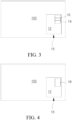
- the monitoring video generated in real time may be displayed in the minimap mode, as shown in FIG. 3 .
- the display window 10 is composed of a main window 12 and a minimap window 14.
- the minimap window 14 is located at a corner of the main window 12 and is configured to display the keyframe.
- the main window 12 is configured to display the monitored targets within the bounding box of the keyframe.
- a rectangular box 16 exists on the keyframe displayed in the minimap window 14 to indicate a position of the monitored target in the keyframe.
- the monitoring video generated in real time may be displayed in the Picture-in-Picture mode, as shown in FIG. 4 .
- the display window 10 is composed of a main window 12 and a child window 18.
- the child window 18 is located at a corner of the main window 12.
- One of the main window 12 and the child window 18 is configured to display the monitoring video generated in real time, and the other is configured to display a primary video including the monitored target from a camera.
- Contents displayed in the main window 12 and the child window 18 are switched by clicking/tapping the child window 18. In this way, two different videos may be viewed simultaneously.
- Step S30 Determine, for each of the primary videos, a bounding box surrounding the monitored target in each subsequent frame.
- the step of determining, for each of the primary videos, the bounding box surrounding the monitored target in each subsequent frame specifically includes: determining the bounding box surrounding the monitored target in each subsequent frame by using an automatic detection algorithm, a coordinate conversion algorithm, or an optical flow method.
- the step of determining the bounding box surrounding the monitored target in each subsequent frame by using the automatic detection algorithm specifically includes: detecting a frame of each inputted primary video at each moment, and acquiring, for each frame, the bounding box surrounding the monitored target.
- the step of determining the bounding box surrounding the monitored target in each subsequent frame by using the coordinate conversion algorithm specifically includes: mapping, through a coordinate conversion algorithm, coordinates of a bounding box in a keyframe at a previous frame moment to a coordinate system where the gantry of the CT machine is located, calculating, according to a physical movement vector of the patient table of the CT machine relative to the gantry of the CT machine between two frames, a position of a bounding box in a frame at a next frame moment of the same primary video in the coordinate system where the gantry of the CT machine is located, then mapping the coordinates to a frame at a next frame moment of each of the primary videos according to coordinate correspondences between cameras that acquire the primary videos and between the cameras and the gantry, and determining a bounding box surrounding the monitored target after coordinate update in the frame at the next frame moment of each of the primary videos.
- the coordinates of the bounding box in each next frame may be calculated, which helps save calculation resources, thereby improving the real-time performance of the monitoring video.
- conversion among coordinates in each frame, camera coordinates, and gantry coordinates may be performed after calibrating internal and external parameters.
- the step of determining the bounding box surrounding the monitored target in the frame at each next frame moment by using the optical flow method specifically includes: calculating coordinates of a bounding box in a frame at a next frame moment of the same primary video through the optical flow method by using coordinates of a bounding box in a keyframe at a previous frame moment as a reference, then mapping, through coordinate conversion, the calculated coordinates of the bounding box in the frame at the next frame moment to a coordinate system where the gantry of the CT machine gantry is located, mapping the coordinates to a frame at a next frame moment of each of the primary videos according to coordinate correspondences between cameras that acquire the primary videos and between the cameras and the gantry, and determining a bounding box surrounding the monitored target after coordinate update in the frame at the next frame moment of each of the primary videos. In this way, the consumption of calculation resources is reduced.
- Step S40 Select, for each frame moment from the frames of the plurality of primary videos, a frame in which the region of the monitored target within the bounding box has a largest area as the keyframe, and generate a monitoring video in real time according to a part of each selected keyframe located within the bounding box. For example, the monitoring video is displayed in the display window 10.
- the monitoring video generated in real time is composed of the keyframes at all frame moments. Therefore, a display mode of the monitoring video is the display mode of the keyframes. Details are not described.
- a monitoring video may be generated in real time according to the primary videos of a plurality of cameras, which can facilitate observation of a patient from a plurality of angles in the monitoring video, thereby helping reduce the loss of focus and visual fatigue as a result of an operator frequently switching the sight among a plurality of videos on a monitoring screen.
- FIG. 2 is a schematic flowchart of another exemplary implementation of the monitoring video generation method.
- the monitoring video generation method includes the following steps:
- the monitored target is detected in each of the keyframes of the secondary video by using an automatic detection algorithm, and the bounding box is determined to surround the monitored target. In this way, automatic operation can be achieved, thereby reducing the labor consumption.
- the monitored target is detected in an initial keyframe of the secondary video by using the automatic detection algorithm and the bounding box is determined to surround the monitored target, or the monitored target is manually selected and the bounding box is manually drawn to surround the monitored target. Then, the bounding box is determined in each subsequent frame according to the bounding box determined in the initial keyframe by using the coordinate conversion algorithm or the optical flow method.
- the coordinate conversion algorithm specifically includes: calculating a movement vector from coordinates of the bounding box in the keyframe at a previous frame moment to coordinates of the bounding box in the keyframe at a next frame moment according to a physical movement vector of the patient table of the CT machine relative to the gantry of the CT machine between two frame moments, and calculating the coordinates of the bounding box in the keyframe at the next frame moment according to the coordinates of the bounding box in the keyframe at the previous frame moment and the coordinate movement vector.
- the coordinates of the bounding box in each next keyframe may be calculated, which helps save calculation resources and generate the monitoring video in real time.
- the optical flow specifically includes: calculating an optical flow between the keyframe at a previous frame moment and the keyframe at a next frame moment by using coordinates of the bounding box in the keyframe at the previous frame moment as a reference, and applying the optical flow to the coordinates of the bounding box in the keyframe at the previous frame moment to calculate coordinates of the bounding box in the keyframe at the next frame moment. In this way, there is no need to frequently read system information, which helps reduce the consumption of calculation resources.
- Step S70 Generate and display a monitoring video in real time according to a part of each of the keyframes of the secondary video located within the bounding box.
- the display mode may be a minimap mode or a Picture-in-Picture mode. Details are not described herein.
- a monitoring video may be generated in real time according to the primary videos of a plurality of cameras, which can facilitate observation of a patient from a plurality of angles in the monitoring video, thereby helping reduce the loss of focus and visual fatigue as a result of an operator frequently switching the sight among a plurality of videos on a monitoring screen.
- the present invention further provides a monitoring video generation system for a CT machine, including a computer-readable storage medium, a processor, and a display.
- the computer-readable storage medium stores code.
- the processor executes the code
- the monitoring video generation system performs the above monitoring video generation method.
- the display has an operating interface 100.
- a display window 10 is arranged on the operating interface 100.
- the display window 10 is configured to display a monitoring video generated in real time. By displaying the monitoring video generated in real time through the display window 10, no additional display screen is required.
- the display displays the generated monitoring video in a minimap mode or a Picture-in-Picture mode in real time.
- the display window 10 is composed of a main window 12 and a minimap window 14.
- the minimap window 14 is located at a corner of the main window 12 and is configured to display the keyframe.
- the main window 12 is configured to display a part of the keyframe located within a bounding box.
- a rectangular box 16 exists on each keyframe displayed in the minimap window 14 to indicate a position of the monitored target in each keyframe. In this way, the region of real interest is zoomed in in the main window 12 while retaining an original image in the minimap window 14 to provide position information.
- the display window 10 is composed of a main window 12 and a child window 18.
- the child window 18 is located at a corner of the main window 12.
- One of the main window 12 and the child window 18 is configured to display the monitoring video generated in real time, and the other is configured to display a primary video including the monitored target from a camera.
- Contents displayed in the main window 12 and the child window 18 are switched by clicking/tapping the child window 18. In this way, two different videos may be viewed simultaneously.
Landscapes
- Health & Medical Sciences (AREA)
- Engineering & Computer Science (AREA)
- Life Sciences & Earth Sciences (AREA)
- Medical Informatics (AREA)
- Physics & Mathematics (AREA)
- Veterinary Medicine (AREA)
- Biomedical Technology (AREA)
- Heart & Thoracic Surgery (AREA)
- Pathology (AREA)
- Molecular Biology (AREA)
- Surgery (AREA)
- Animal Behavior & Ethology (AREA)
- General Health & Medical Sciences (AREA)
- Public Health (AREA)
- Biophysics (AREA)
- Nuclear Medicine, Radiotherapy & Molecular Imaging (AREA)
- Radiology & Medical Imaging (AREA)
- High Energy & Nuclear Physics (AREA)
- Optics & Photonics (AREA)
- Theoretical Computer Science (AREA)
- Multimedia (AREA)
- General Physics & Mathematics (AREA)
- Computer Vision & Pattern Recognition (AREA)
- Pulmonology (AREA)
- Signal Processing (AREA)
- Physiology (AREA)
- Dentistry (AREA)
- Oral & Maxillofacial Surgery (AREA)
- Human Computer Interaction (AREA)
- Apparatus For Radiation Diagnosis (AREA)
- Closed-Circuit Television Systems (AREA)
Description
- The present invention relates to a monitoring video generation method and a monitoring video generation system configured to perform a monitoring video generation method.
- During movement of a patient into a CT machine through a patient table, an operator observes, through the CT machine or a plurality of cameras in a scanning room, a status/action of the patient from all angles, which overcomes blind spots caused by the room layout and the patient orientation, thereby ensuring better patient care and patient safety during the entire CT examination.
- In an existing method, a camera stream is displayed on a dedicated monitoring screen, and a video corresponding to each camera is played separately in a specific region of the monitoring screen. The operator needs to frequently switch the sight among the plurality of videos on the monitoring screen to capture a desired image, which easily leads to the loss of focus and visual fatigue.
-
WO 2021/110613 A1 refers to an apparatus for monitoring a subject during CT-imaging and comprises an image providing unit providing a first monitoring image and a second monitoring image acquired at different support positions, a monitoring position providing unit providing a first monitoring position of a region of interest in the first monitoring image, a support position providing unit providing support position data of the support positions, a position map providing unit providing a position map mapping calibration support positions to calibration monitoring positions, and a region of interest position determination unit determining a position of the region of interest in the second monitoring image based on the first monitoring position, the support position data, and the position map. The apparatus allows to determine the position of the region of interest. - The present invention is intended to provide a monitoring video generation method, which can facilitate observation of a patient from a plurality of angles in a monitoring video.
- The present invention is further intended to provide a monitoring video generation system, which can facilitate observation of a patient from a plurality of angles in a monitoring video.
- The present invention provides a monitoring video generation method applicable to a CT machine. A monitored target is located on a patient table of the CT machine. The patient table of the CT machine is movable relative to a gantry of the CT machine in an extending direction. The monitoring video generation method includes: acquiring a plurality of primary videos including the monitored target, where fields of view of the plurality of primary videos are fixed relative to a position of the gantry of the CT machine; determining a keyframe according to a region in an initial frame of each of the primary videos surrounding a monitored target, and determining a bounding box surrounding the monitored target in the keyframe; determining, for each of the primary videos, a bounding box surrounding the monitored target in each subsequent frame; and selecting, for each frame moment from the frames of the plurality of primary videos, a frame in which the region of the monitored target within the bounding box has a largest area as the keyframe, and generating a monitoring video in real time according to a part of each selected keyframe located within the bounding box.
- According to the monitoring video generation method provided in the present invention, a monitoring video may be generated in real time according to the primary videos of a plurality of cameras, which can facilitate observation of a patient from a plurality of angles in the monitoring video, thereby helping reduce the loss of focus and visual fatigue as a result of an operator frequently switching the sight among a plurality of videos on a monitoring screen.
- In an exemplary implementation of the monitoring video generation method, the step of determining the keyframe according to the region in the initial frame of each of the primary videos surrounding the monitored target specifically includes: determining the region in the initial frame of each of the primary videos surrounding the monitored target through an automatic detection algorithm or manual selection, and selecting a frame in the initial frames in which the region surrounding the monitored target has a largest area as the keyframe.
- In another exemplary implementation of the monitoring video generation method, the step of determining, for each of the primary videos, the bounding box surrounding the monitored target in each subsequent frame specifically includes: determining, for each of the primary videos, the bounding box surrounding the monitored target in each subsequent frame by using an automatic detection algorithm, a coordinate conversion algorithm, or an optical flow method.
- In still another exemplary implementation of the monitoring video generation method, the step of determining the bounding box by using the coordinate conversion algorithm specifically includes: mapping, through a coordinate conversion algorithm, coordinates of a bounding box in a keyframe at a previous frame moment to a coordinate system where the gantry of the CT machine is located, calculating, according to a physical movement vector of the patient table of the CT machine relative to the gantry of the CT machine between two frames, a position of a bounding box in a frame at a next frame moment of the same primary video in the coordinate system where the gantry of the CT machine is located, then mapping the coordinates to a frame at a next frame moment of each of the primary videos according to coordinate correspondences between cameras that acquire the primary videos and between the cameras and the gantry, and determining a bounding box surrounding the monitored target after coordinate update in the frame at the next frame moment of each of the primary videos. Through the coordinate conversion, the coordinates of the bounding box in each subsequent frame may be calculated, which helps save calculation resources, thereby improving the real-time performance of the monitoring video.
- In yet another exemplary implementation of the monitoring video generation method, the step of determining the bounding box by using the optical flow method specifically includes: calculating coordinates of a bounding box in a frame at a next frame moment of the same primary video through the optical flow method by using coordinates of a bounding box in a keyframe at a previous frame moment as a reference, then mapping, through coordinate conversion, the calculated coordinates of the bounding box in the frame at the next frame moment to a coordinate system where the gantry of the CT machine gantry is located, mapping the coordinates to a frame at a next frame moment of each of the primary videos according to coordinate correspondences between cameras that acquire the primary videos and between the cameras and the gantry, and determining a bounding box surrounding the monitored target after coordinate update in the frame at the next frame moment of each of the primary videos. In this way, the consumption of calculation resources is reduced.
- The present invention further provides a monitoring video generation method. A monitored target is located on a patient table of a CT machine. The patient table of the CT machine is movable relative to a gantry of the CT machine in an extending direction. The monitoring video generation method includes: acquiring a plurality of primary videos including the monitored target, where fields of view of the plurality of primary videos are fixed relative to a position of the gantry of the CT machine; splicing and/or stacking the plurality of primary videos to form a secondary video composed of keyframes at all frame moments; determining a bounding box in each of the keyframes of the secondary video to surround the monitored target; and generating a monitoring video in real time according to a part of each of the keyframes of the secondary video located within the bounding box.
- According to the monitoring video generation method provided in the present invention, a monitoring video may be generated in real time according to the primary videos of a plurality of cameras, which can facilitate observation of a patient from a plurality of angles in the monitoring video, thereby helping reduce the loss of focus and visual fatigue as a result of an operator frequently switching the sight among a plurality of videos on a monitoring screen.
- In an exemplary implementation of the monitoring video generation method, the step of determining the bounding box in each of the keyframes of the secondary video to surround the monitored target specifically includes: determining the bounding box in each of the keyframes of the secondary video by using an automatic detection algorithm to surround the monitored target. In this way, automatic operation can be achieved, thereby reducing the labor consumption.
- In another exemplary implementation of the monitoring video generation method, the step of determining the bounding box in each of the keyframes of the secondary video to surround the monitored target specifically includes: determining a bounding box in an initial keyframe through an automatic detection algorithm or manual selection to surround the monitored target, and determining a bounding box in each subsequent keyframe by using a coordinate conversion algorithm according to the bounding box determined in the initial keyframe. The coordinate conversion algorithm includes: calculating a movement vector from coordinates of the bounding box in the keyframe at a previous frame moment to coordinates of the bounding box in the keyframe at a next frame moment according to a physical movement vector of the patient table of the CT machine relative to the gantry of the CT machine between two frame moments, and calculating the coordinates of the bounding box in the keyframe at the next frame moment according to the coordinates of the bounding box in the keyframe at the previous frame moment and the coordinate movement vector. Through the coordinate conversion, the coordinates of the bounding box in each subsequent keyframe may be calculated, which helps save calculation resources, thereby improving the real-time performance of the monitoring video.
- In another exemplary implementation of the monitoring video generation method, the step of determining the bounding box in each of the keyframes of the secondary video to surround the monitored target specifically includes: determining a bounding box in an initial keyframe through an automatic detection algorithm or manual selection to surround the monitored target, and determining a bounding box in each subsequent keyframe by using an optical flow method according to the bounding box determined in the initial keyframe. In this way, the consumption of calculation resources is reduced.
- The present invention further provides a monitoring video generation system, including a computer-readable storage medium and a processor. The computer-readable storage medium stores code. When the processor executes the code, the monitoring video generation system performs the above monitoring video generation method. According to the monitoring video generation system, a monitoring video may be generated in real time according to the primary videos of a plurality of cameras, which can facilitate observation of a patient from a plurality of angles in the monitoring video, thereby helping reduce the loss of focus and visual fatigue as a result of an operator frequently switching the sight among a plurality of videos on a monitoring screen.
- In an exemplary implementation of the monitoring video generation system, the monitoring video generation system further includes a display. The display has a display window, and the display window is configured to display a monitoring video generated in real time. The display displays the monitoring video generated in real time in a minimap mode or a Picture-in-Picture mode.
- In another exemplary implementation of the monitoring video generation system, in the minimap mode, the display window is composed of a main window and a minimap window. The minimap window is configured to display a keyframe at each frame moment. The main window is configured to display a part of each keyframe located within a bounding box. A rectangular box exists on each keyframe displayed in the minimap window to indicate a position of the monitored target in each keyframe. In this way, the region of real interest is zoomed in in the main window while retaining an original image in the minimap window to provide position information.
- In still another exemplary implementation of the monitoring video generation system, the display window in the Picture-in-Picture mode is composed of a main window and a child window. One of the main window and the child window is configured to display the monitoring video generated in real time, and the other is configured to display a primary video including the monitored target from a camera. Contents displayed in the main window and the child window are switched by clicking/tapping the child window. In this way, two different videos may be viewed simultaneously.
- The following drawings are merely exemplary descriptions and explanations and do not limit the scope of the present invention.
-
FIG. 1 is a schematic flowchart of an exemplary implementation of a monitoring video generation method. -
FIG. 2 is a schematic flowchart of another exemplary implementation of the monitoring video generation method. -
FIG. 3 is a schematic diagram describing a minimap mode. -
FIG. 4 is a schematic diagram describing a Picture-in-Picture mode. - Reference numerals:
- 100 Operating interface
- 10 Display window
- 12 Main window
- 14 Minimap window
- 16 Rectangular box
- 18 Child window
- For clearer understanding of the technical features, objectives, and effects of the present invention, specific implementations of the present invention are described with reference to the drawings. The same labels in the figures represent components with the same structure or similar structures but the same function.
- Herein, "exemplary" means "being used as an instance, example, or description", and any illustration or implementation described as "exemplary" herein should not be interpreted as a more preferred or advantageous technical solution.
-
FIG. 1 is a schematic flowchart of an exemplary implementation of a monitoring video generation method. The monitoring video generation method is applicable to a CT machine. The CT machine is also referred to as a computed X-ray tomographic unit. During movement of a patient into a CT machine through a patient table, an operator observes, through the CT machine or a plurality of cameras in a scanning room, a status/action of the patient from all angles, which overcomes blind spots caused by the room layout and the patient orientation, thereby ensuring better patient care and patient safety during the entire CT examination. - The CT machine includes a display with a display window. A monitored target is located on a patient table of the CT machine. The patient table of the CT machine is movable relative to a gantry of the CT machine in an extending direction. Referring to
FIG. 1 , the monitoring video generation method includes the following steps: - Step S10: Acquire a plurality of primary videos including the monitored target (such as a patient), where fields of view of the plurality of primary videos are fixed relative to a position of the gantry of the CT machine.
- Step S20: Determine a keyframe according to a region in an initial frame of each of the primary videos surrounding the monitored target, and determining a bounding box surrounding the monitored target in the keyframe. The "bounding box surrounding the monitored target" therein is explained as a "bounding box surrounding a region where the monitored target is displayed".
- In an exemplary implementation, the keyframe may be determined through manual selection from the plurality of primary videos acquired in step S10, which specifically includes: comparing areas of the monitored target in the initial frames, selecting an initial frame in which the monitored target has a largest area as the keyframe, and drawing a bounding box on the keyframe, where the bounding box needs to surround the monitored target.
- In another exemplary implementation, the keyframe may be determined through an automatic detection algorithm from the plurality of primary videos acquired in step S10, which specifically includes: inputting the initial frames of the acquired primary videos into the automatic detection algorithm, and executing the algorithm to automatically select an initial frame in which the monitored target has a largest area as the keyframe and to obtain coordinates of the bounding box on the keyframe. In this case, the bounding box is invisible.
- As a frame of the monitoring video, the acquired keyframe is displayed in real time on a display window. As shown in
FIG. 3 and FIG. 4 , the CT machine includes a display with adisplay window 10. The display has anoperating interface 100 configured to display CT scan results. Thedisplay window 10 configured to display the monitoring video generated in real time is arranged at a corner of the operatinginterface 100. The monitoring video generated in real time is displayed in a minimap mode or a Picture-in-Picture mode, for example. - In an exemplary implementation, the monitoring video generated in real time may be displayed in the minimap mode, as shown in
FIG. 3 . In the minimap mode, thedisplay window 10 is composed of amain window 12 and aminimap window 14. Theminimap window 14 is located at a corner of themain window 12 and is configured to display the keyframe. Themain window 12 is configured to display the monitored targets within the bounding box of the keyframe. Arectangular box 16 exists on the keyframe displayed in theminimap window 14 to indicate a position of the monitored target in the keyframe. - In another exemplary implementation, the monitoring video generated in real time may be displayed in the Picture-in-Picture mode, as shown in
FIG. 4 . In the Picture-in-Picture mode, thedisplay window 10 is composed of amain window 12 and achild window 18. Thechild window 18 is located at a corner of themain window 12. One of themain window 12 and thechild window 18 is configured to display the monitoring video generated in real time, and the other is configured to display a primary video including the monitored target from a camera. Contents displayed in themain window 12 and thechild window 18 are switched by clicking/tapping thechild window 18. In this way, two different videos may be viewed simultaneously. - Step S30: Determine, for each of the primary videos, a bounding box surrounding the monitored target in each subsequent frame.
- The step of determining, for each of the primary videos, the bounding box surrounding the monitored target in each subsequent frame specifically includes: determining the bounding box surrounding the monitored target in each subsequent frame by using an automatic detection algorithm, a coordinate conversion algorithm, or an optical flow method.
- In an exemplary implementation, the step of determining the bounding box surrounding the monitored target in each subsequent frame by using the automatic detection algorithm specifically includes: detecting a frame of each inputted primary video at each moment, and acquiring, for each frame, the bounding box surrounding the monitored target.
- In another exemplary implementation of the monitoring video generation method, the step of determining the bounding box surrounding the monitored target in each subsequent frame by using the coordinate conversion algorithm specifically includes: mapping, through a coordinate conversion algorithm, coordinates of a bounding box in a keyframe at a previous frame moment to a coordinate system where the gantry of the CT machine is located, calculating, according to a physical movement vector of the patient table of the CT machine relative to the gantry of the CT machine between two frames, a position of a bounding box in a frame at a next frame moment of the same primary video in the coordinate system where the gantry of the CT machine is located, then mapping the coordinates to a frame at a next frame moment of each of the primary videos according to coordinate correspondences between cameras that acquire the primary videos and between the cameras and the gantry, and determining a bounding box surrounding the monitored target after coordinate update in the frame at the next frame moment of each of the primary videos. Through the coordinate conversion, the coordinates of the bounding box in each next frame may be calculated, which helps save calculation resources, thereby improving the real-time performance of the monitoring video. A person skilled in the art knows that conversion among coordinates in each frame, camera coordinates, and gantry coordinates may be performed after calibrating internal and external parameters.
- In still another exemplary implementation of the monitoring video generation method, the step of determining the bounding box surrounding the monitored target in the frame at each next frame moment by using the optical flow method specifically includes: calculating coordinates of a bounding box in a frame at a next frame moment of the same primary video through the optical flow method by using coordinates of a bounding box in a keyframe at a previous frame moment as a reference, then mapping, through coordinate conversion, the calculated coordinates of the bounding box in the frame at the next frame moment to a coordinate system where the gantry of the CT machine gantry is located, mapping the coordinates to a frame at a next frame moment of each of the primary videos according to coordinate correspondences between cameras that acquire the primary videos and between the cameras and the gantry, and determining a bounding box surrounding the monitored target after coordinate update in the frame at the next frame moment of each of the primary videos. In this way, the consumption of calculation resources is reduced.
- Step S40: Select, for each frame moment from the frames of the plurality of primary videos, a frame in which the region of the monitored target within the bounding box has a largest area as the keyframe, and generate a monitoring video in real time according to a part of each selected keyframe located within the bounding box. For example, the monitoring video is displayed in the
display window 10. The monitoring video generated in real time is composed of the keyframes at all frame moments. Therefore, a display mode of the monitoring video is the display mode of the keyframes. Details are not described. - According to the monitoring video generation method provided in the present invention, a monitoring video may be generated in real time according to the primary videos of a plurality of cameras, which can facilitate observation of a patient from a plurality of angles in the monitoring video, thereby helping reduce the loss of focus and visual fatigue as a result of an operator frequently switching the sight among a plurality of videos on a monitoring screen.
- In addition, by arranging the
display window 10 on theoperating interface 100 of the display of the CT machine and displaying the monitoring video on thedisplay window 10, no additional display screen is required, which can avoid the loss of focus and visual fatigue as a result of an operator switching the sight by a long distance between the operatinginterface 100 and the monitoring screen. -
FIG. 2 is a schematic flowchart of another exemplary implementation of the monitoring video generation method. Referring toFIG. 2 , the monitoring video generation method includes the following steps: - Step S10: Acquire a plurality of primary videos including the monitored target, where fields of view of the plurality of primary videos are fixed relative to a position of the gantry of the CT machine.
- Step S50: Splice and/or stack the plurality of primary videos to form a secondary video composed of keyframes at all frame moments. The splicing and/or stacking of the primary videos is implemented by using commonly used methods.
- Step S60: Determine a bounding box in each of the keyframes of the secondary video to surround the monitored target.
- In an exemplary implementation, the monitored target is detected in each of the keyframes of the secondary video by using an automatic detection algorithm, and the bounding box is determined to surround the monitored target. In this way, automatic operation can be achieved, thereby reducing the labor consumption.
- In another exemplary implementation, the monitored target is detected in an initial keyframe of the secondary video by using the automatic detection algorithm and the bounding box is determined to surround the monitored target, or the monitored target is manually selected and the bounding box is manually drawn to surround the monitored target. Then, the bounding box is determined in each subsequent frame according to the bounding box determined in the initial keyframe by using the coordinate conversion algorithm or the optical flow method.
- The coordinate conversion algorithm specifically includes: calculating a movement vector from coordinates of the bounding box in the keyframe at a previous frame moment to coordinates of the bounding box in the keyframe at a next frame moment according to a physical movement vector of the patient table of the CT machine relative to the gantry of the CT machine between two frame moments, and calculating the coordinates of the bounding box in the keyframe at the next frame moment according to the coordinates of the bounding box in the keyframe at the previous frame moment and the coordinate movement vector. Through the coordinate conversion, the coordinates of the bounding box in each next keyframe may be calculated, which helps save calculation resources and generate the monitoring video in real time.
- The optical flow specifically includes: calculating an optical flow between the keyframe at a previous frame moment and the keyframe at a next frame moment by using coordinates of the bounding box in the keyframe at the previous frame moment as a reference, and applying the optical flow to the coordinates of the bounding box in the keyframe at the previous frame moment to calculate coordinates of the bounding box in the keyframe at the next frame moment. In this way, there is no need to frequently read system information, which helps reduce the consumption of calculation resources.
- Step S70: Generate and display a monitoring video in real time according to a part of each of the keyframes of the secondary video located within the bounding box. The display mode may be a minimap mode or a Picture-in-Picture mode. Details are not described herein.
- According to the monitoring video generation method provided in the present invention, a monitoring video may be generated in real time according to the primary videos of a plurality of cameras, which can facilitate observation of a patient from a plurality of angles in the monitoring video, thereby helping reduce the loss of focus and visual fatigue as a result of an operator frequently switching the sight among a plurality of videos on a monitoring screen.
- The present invention further provides a monitoring video generation system for a CT machine, including a computer-readable storage medium, a processor, and a display. The computer-readable storage medium stores code. When the processor executes the code, the monitoring video generation system performs the above monitoring video generation method. The display has an
operating interface 100. Adisplay window 10 is arranged on theoperating interface 100. Thedisplay window 10 is configured to display a monitoring video generated in real time. By displaying the monitoring video generated in real time through thedisplay window 10, no additional display screen is required. - The display displays the generated monitoring video in a minimap mode or a Picture-in-Picture mode in real time.
- In the minimap mode, the
display window 10 is composed of amain window 12 and aminimap window 14. Theminimap window 14 is located at a corner of themain window 12 and is configured to display the keyframe. Themain window 12 is configured to display a part of the keyframe located within a bounding box. Arectangular box 16 exists on each keyframe displayed in theminimap window 14 to indicate a position of the monitored target in each keyframe. In this way, the region of real interest is zoomed in in themain window 12 while retaining an original image in theminimap window 14 to provide position information. - In the Picture-in-Picture mode, the
display window 10 is composed of amain window 12 and achild window 18. Thechild window 18 is located at a corner of themain window 12. One of themain window 12 and thechild window 18 is configured to display the monitoring video generated in real time, and the other is configured to display a primary video including the monitored target from a camera. Contents displayed in themain window 12 and thechild window 18 are switched by clicking/tapping thechild window 18. In this way, two different videos may be viewed simultaneously. - It should be understood that although the description is illustrated according to each embodiment, each embodiment does not necessarily include an independent technical solution. The illustration of the specification is merely for clarity. A person skilled in the art should consider the description as a whole, and the technical solutions in the embodiments may be properly combined to form other implementations that a person skilled in the art can understand.
- The series of detailed descriptions listed above are merely specific illustrations of the feasible embodiments of the present invention, and are not intended to limit the protection scope of the present invention. Any equivalent implementations or changes made without departing from the present invention, such as the combination, segmentation, or repetition of features, should be included in the protection scope of the present invention.
Claims (13)
- A monitoring video generation method, applicable to a CT machine, wherein a monitored target is located on a patient table of the CT machine, and the patient table of the CT machine is movable relative to a gantry of the CT machine in an extending direction, the monitoring video generation method comprising:Acquiring (S10) a plurality of primary videos comprising the monitored target, wherein fields of view of the plurality of primary videos are fixed relative to a position of the gantry of the CT machine;characterized in that it further comprises:Determining (S20) a keyframe according to a region in an initial frame of each of the primary videos surrounding the monitored target, and determining a bounding box surrounding the monitored target in the keyframe;Determining (S30), for each of the primary videos, a bounding box surrounding the monitored target in each subsequent frame; andSelecting (S40), for each frame moment from the frames of the plurality of primary videos, a frame in which the region of the monitored target within the bounding box has a largest area as the keyframe, and generating a monitoring video in real time according to a part of each selected keyframe located within the bounding box.
- The monitoring video generation method according to claim 1, wherein the step of determining (S20) the keyframe according to the region in the initial frame of each of the primary videos surrounding the monitored target specifically comprises: determining the region in the initial frame of each of the primary videos surrounding the monitored target through an automatic detection algorithm or manual selection, and selecting a frame in the initial frames in which the region surrounding the monitored target has a largest area as the keyframe.
- The monitoring video generation method according to claim 1, wherein the step of determining (S30), for each of the primary videos, the bounding box surrounding the monitored target in each subsequent frame specifically comprises: determining, for each of the primary videos, the bounding box surrounding the monitored target in each subsequent frame by using an automatic detection algorithm, a coordinate conversion algorithm, or an optical flow method.
- The monitoring video generation method according to claim 3, wherein the step of determining (S30) the bounding box by using the coordinate conversion algorithm specifically comprises: mapping, through a coordinate conversion algorithm, coordinates of a bounding box in a keyframe at a previous frame moment to a coordinate system where the gantry of the CT machine is located, calculating, according to a physical movement vector of the patient table of the CT machine relative to the gantry of the CT machine between two frames, a position of a bounding box in a frame at a next frame moment of the same primary video in the coordinate system where the gantry of the CT machine is located, then mapping the coordinates to a frame at a next frame moment of each of the primary videos according to coordinate correspondences between cameras that acquire the primary videos and between the cameras and the gantry, and determining a bounding box surrounding the monitored target after coordinate update in the frame at the next frame moment of each of the primary videos.
- The monitoring video generation method according to claim 3, wherein the step of determining (S30) the bounding box by using the optical flow method specifically comprises: calculating coordinates of a bounding box in a frame at a next frame moment of the same primary video through the optical flow method by using coordinates of a bounding box in a keyframe at a previous frame moment as a reference, then mapping, through coordinate conversion, the calculated coordinates of the bounding box in the frame at the next frame moment to a coordinate system where the gantry of the CT machine gantry is located, mapping the coordinates to a frame at a next frame moment of each of the primary videos according to coordinate correspondences between cameras that acquire the primary videos and between the cameras and the gantry, and determining a bounding box surrounding the monitored target after coordinate update in the frame at the next frame moment of each of the primary videos.
- A monitoring video generation method, wherein a monitored target is located on a patient table of a CT machine, and the patient table of the CT machine is movable relative to a gantry of the CT machine in an extending direction, the monitoring video generation method comprising:Acquiring (S10) a plurality of primary videos comprising the monitored target, wherein fields of view of the plurality of primary videos are fixed relative to a position of the gantry of the CT machine;characterized in that it further comprises:splicing and/or stacking (S50) the plurality of primary videos to form a secondary video composed of keyframes at all frame moments;determining (S60) a bounding box in each of the keyframes of the secondary video to surround the monitored target; andgenerating (S70) a monitoring video in real time according to a part of each of the keyframes of the secondary video located within the bounding box.
- The monitoring video generation method according to claim 6, wherein the step of determining (S360) the bounding box in each of the keyframes of the secondary video to surround the monitored target specifically comprises: determining the bounding box in each of the keyframes of the secondary video by using an automatic detection algorithm to surround the monitored target.
- The monitoring video generation method according to claim 6, wherein the step of determining (S60) the bounding box in each of the keyframes of the secondary video to surround the monitored target specifically comprises: determining a bounding box in an initial keyframe through an automatic detection algorithm or manual selection to surround the monitored target, and determining a bounding box in each subsequent keyframe by using a coordinate conversion algorithm according to the bounding box determined in the initial keyframe, wherein the coordinate conversion algorithm comprises: calculating a movement vector from coordinates of the bounding box in the keyframe at a previous frame moment to coordinates of the bounding box in the keyframe at a next frame moment according to a physical movement vector of the patient table of the CT machine relative to the gantry of the CT machine between two frame moments, and calculating the coordinates of the bounding box in the keyframe at the next frame moment according to the coordinates of the bounding box in the keyframe at the previous frame moment and the coordinate movement vector.
- The monitoring video generation method according to claim 6, wherein the step of determining (S60) the bounding box in each of the keyframes of the secondary video to surround the monitored target specifically comprises: determining a bounding box in an initial keyframe through an automatic detection algorithm or manual selection to surround the monitored target, and determining a bounding box in each subsequent keyframe by using an optical flow method according to the bounding box determined in the initial keyframe.
- A monitoring video generation system, comprising a computer-readable storage medium and a processor, wherein the computer-readable storage medium stores code, and when the processor executes the code, the monitoring video generation system performs the monitoring video generation method according to any of claims 1 to 9.
- The monitoring video generation system according to claim 10, further comprising a display, wherein the display has a display window (10), the display window (10) is configured to display a monitoring video generated in real time, and the display displays the monitoring video generated in real time in a minimap mode or a Picture-in-Picture mode.
- The monitoring video generation system according to claim 11, wherein in the minimap mode, the display window (10) is composed of a main window (12) and a minimap window (14), the minimap window (14) is configured to display a keyframe at each frame moment, the main window (12) is configured to display a part of each keyframe located within a bounding box, and a rectangular box exists on each keyframe displayed in the minimap window (14) to indicate a position of the monitored target in each keyframe.
- The monitoring video generation system according to claim 11, wherein the display window (10) in the Picture-in-Picture mode is composed of a main window (12) and a child window (18), one of the main window (12) and the child window (18) is configured to display the monitoring video generated in real time, the other is configured to display a primary video comprising the monitored target from a camera, and the contents displayed in the main window (12) and the child window (18) are switched by clicking/tapping the child window (18).
Applications Claiming Priority (2)
| Application Number | Priority Date | Filing Date | Title |
|---|---|---|---|
| CN202211095722.0A CN117676073A (en) | 2022-09-08 | 2022-09-08 | Surveillance video generation method and surveillance video generation system |
| PCT/CN2023/111078 WO2024051413A1 (en) | 2022-09-08 | 2023-08-03 | Monitoring video generation method and monitoring video generation system |
Publications (3)
| Publication Number | Publication Date |
|---|---|
| EP4478957A1 EP4478957A1 (en) | 2024-12-25 |
| EP4478957B1 true EP4478957B1 (en) | 2025-02-26 |
| EP4478957C0 EP4478957C0 (en) | 2025-02-26 |
Family
ID=87933936
Family Applications (1)
| Application Number | Title | Priority Date | Filing Date |
|---|---|---|---|
| EP23765160.9A Active EP4478957B1 (en) | 2022-09-08 | 2023-08-03 | Monitoring video generation method and monitoring video generation system |
Country Status (4)
| Country | Link |
|---|---|
| US (1) | US20260082020A1 (en) |
| EP (1) | EP4478957B1 (en) |
| CN (1) | CN117676073A (en) |
| WO (1) | WO2024051413A1 (en) |
Families Citing this family (1)
| Publication number | Priority date | Publication date | Assignee | Title |
|---|---|---|---|---|
| WO2026131258A1 (en) * | 2024-12-18 | 2026-06-25 | Koninklijke Philips N.V. | Continuous patient observation during medical imaging examinations |
Family Cites Families (8)
| Publication number | Priority date | Publication date | Assignee | Title |
|---|---|---|---|---|
| CN103610470A (en) * | 2013-12-05 | 2014-03-05 | 赛诺威盛科技(北京)有限公司 | CT device scanning real-time monitoring device and method |
| US10861302B2 (en) * | 2017-08-17 | 2020-12-08 | Bossa Nova Robotics Ip, Inc. | Robust motion filtering for real-time video surveillance |
| US10873697B1 (en) * | 2019-03-29 | 2020-12-22 | Facebook, Inc. | Identifying regions of interest in captured video data objects by detecting movement within higher resolution frames of the regions |
| EP3832602A1 (en) * | 2019-12-03 | 2021-06-09 | Koninklijke Philips N.V. | Apparatus, method and computer program for monitoring a subject during a medical imaging procedure |
| CN111918023B (en) * | 2020-06-29 | 2021-10-22 | 北京大学 | A monitoring target tracking method and device |
| CN112509000A (en) * | 2020-11-20 | 2021-03-16 | 合肥市卓迩无人机科技服务有限责任公司 | Moving target tracking algorithm for multi-path 4K quasi-real-time spliced video |
| CN113112519B (en) * | 2021-04-23 | 2023-04-18 | 电子科技大学 | Key frame screening method based on interested target distribution |
| CN113840159B (en) * | 2021-09-26 | 2024-07-16 | 北京沃东天骏信息技术有限公司 | Video processing method, device, computer system and readable storage medium |
-
2022
- 2022-09-08 CN CN202211095722.0A patent/CN117676073A/en active Pending
-
2023
- 2023-08-03 US US19/108,831 patent/US20260082020A1/en active Pending
- 2023-08-03 EP EP23765160.9A patent/EP4478957B1/en active Active
- 2023-08-03 WO PCT/CN2023/111078 patent/WO2024051413A1/en not_active Ceased
Also Published As
| Publication number | Publication date |
|---|---|
| WO2024051413A1 (en) | 2024-03-14 |
| EP4478957A1 (en) | 2024-12-25 |
| CN117676073A (en) | 2024-03-08 |
| EP4478957C0 (en) | 2025-02-26 |
| US20260082020A1 (en) | 2026-03-19 |
Similar Documents
| Publication | Publication Date | Title |
|---|---|---|
| US8335357B2 (en) | Image processing apparatus | |
| JP4070493B2 (en) | X-ray diagnostic apparatus and medical image analysis apparatus | |
| JP5883147B2 (en) | Image display device and medical image pickup device | |
| CN103181775B (en) | For detecting the method and system of patient body's cursor position | |
| US20170209110A1 (en) | Apparatus and methods for a projection display device on x-ray imaging devices | |
| JPH0876741A (en) | Image display device | |
| CN103491877B (en) | Medical image display device, medical image display method | |
| JP2015228954A (en) | Image processing device and image processing method | |
| CN109646047B (en) | Display method for operation guidance of ultrasonic equipment | |
| US20220301166A1 (en) | Methods, apparatuses and systems for surview scan | |
| US10129471B2 (en) | Method, apparatus and system for detecting location of laser point on screen | |
| WO2024051413A1 (en) | Monitoring video generation method and monitoring video generation system | |
| JP2006189712A (en) | Information presenting apparatus, information presenting method, and program | |
| EP3866104A1 (en) | A camera system with multiple cameras | |
| JP2020142018A (en) | Dynamic image analysis system and dynamic image processing device | |
| CN113793422A (en) | Display control method of three-dimensional model, electronic device and readable storage medium | |
| JP5701208B2 (en) | Medical image display device and medical image display method | |
| EP2662025A1 (en) | Ultrasonic diagnostic apparatus and control method thereof | |
| US20250022576A1 (en) | Medical imaging method and medical imaging system | |
| WO2018035736A1 (en) | Display method and device for intelligent glasses | |
| EP4491123A1 (en) | Operating method for medical imaging system, and medical imaging system | |
| JPH0341307A (en) | Systems for picking up image and preparing drawing | |
| JP2001356751A (en) | Image display system | |
| JP2019068339A (en) | Image processing apparatus, image processing method and program | |
| CN117369913A (en) | Image display method, image display device, storage medium, and image display apparatus |
Legal Events
| Date | Code | Title | Description |
|---|---|---|---|
| STAA | Information on the status of an ep patent application or granted ep patent |
Free format text: STATUS: UNKNOWN |
|
| STAA | Information on the status of an ep patent application or granted ep patent |
Free format text: STATUS: THE INTERNATIONAL PUBLICATION HAS BEEN MADE |
|
| GRAP | Despatch of communication of intention to grant a patent |
Free format text: ORIGINAL CODE: EPIDOSNIGR1 |
|
| STAA | Information on the status of an ep patent application or granted ep patent |
Free format text: STATUS: GRANT OF PATENT IS INTENDED |
|
| PUAI | Public reference made under article 153(3) epc to a published international application that has entered the european phase |
Free format text: ORIGINAL CODE: 0009012 |
|
| 17P | Request for examination filed |
Effective date: 20240917 |
|
| AK | Designated contracting states |
Kind code of ref document: A1 Designated state(s): AL AT BE BG CH CY CZ DE DK EE ES FI FR GB GR HR HU IE IS IT LI LT LU LV MC ME MK MT NL NO PL PT RO RS SE SI SK SM TR |
|
| GRAS | Grant fee paid |
Free format text: ORIGINAL CODE: EPIDOSNIGR3 |
|
| GRAA | (expected) grant |
Free format text: ORIGINAL CODE: 0009210 |
|
| STAA | Information on the status of an ep patent application or granted ep patent |
Free format text: STATUS: THE PATENT HAS BEEN GRANTED |
|
| AK | Designated contracting states |
Kind code of ref document: B1 Designated state(s): AL AT BE BG CH CY CZ DE DK EE ES FI FR GB GR HR HU IE IS IT LI LT LU LV MC ME MK MT NL NO PL PT RO RS SE SI SK SM TR |
|
| REG | Reference to a national code |
Ref country code: GB Ref legal event code: FG4D |
|
| REG | Reference to a national code |
Ref country code: CH Ref legal event code: EP |
|
| REG | Reference to a national code |
Ref country code: DE Ref legal event code: R096 Ref document number: 602023002227 Country of ref document: DE |
|
| REG | Reference to a national code |
Ref country code: IE Ref legal event code: FG4D |
|
| U01 | Request for unitary effect filed |
Effective date: 20250226 |
|
| U07 | Unitary effect registered |
Designated state(s): AT BE BG DE DK EE FI FR IT LT LU LV MT NL PT RO SE SI Effective date: 20250306 |
|
| PG25 | Lapsed in a contracting state [announced via postgrant information from national office to epo] |
Ref country code: RS Free format text: LAPSE BECAUSE OF FAILURE TO SUBMIT A TRANSLATION OF THE DESCRIPTION OR TO PAY THE FEE WITHIN THE PRESCRIBED TIME-LIMIT Effective date: 20250526 |
|
| PG25 | Lapsed in a contracting state [announced via postgrant information from national office to epo] |
Ref country code: PL Free format text: LAPSE BECAUSE OF FAILURE TO SUBMIT A TRANSLATION OF THE DESCRIPTION OR TO PAY THE FEE WITHIN THE PRESCRIBED TIME-LIMIT Effective date: 20250226 |
|
| PG25 | Lapsed in a contracting state [announced via postgrant information from national office to epo] |
Ref country code: ES Free format text: LAPSE BECAUSE OF FAILURE TO SUBMIT A TRANSLATION OF THE DESCRIPTION OR TO PAY THE FEE WITHIN THE PRESCRIBED TIME-LIMIT Effective date: 20250226 |
|
| PG25 | Lapsed in a contracting state [announced via postgrant information from national office to epo] |
Ref country code: IS Free format text: LAPSE BECAUSE OF FAILURE TO SUBMIT A TRANSLATION OF THE DESCRIPTION OR TO PAY THE FEE WITHIN THE PRESCRIBED TIME-LIMIT Effective date: 20250626 Ref country code: NO Free format text: LAPSE BECAUSE OF FAILURE TO SUBMIT A TRANSLATION OF THE DESCRIPTION OR TO PAY THE FEE WITHIN THE PRESCRIBED TIME-LIMIT Effective date: 20250526 |
|
| PG25 | Lapsed in a contracting state [announced via postgrant information from national office to epo] |
Ref country code: HR Free format text: LAPSE BECAUSE OF FAILURE TO SUBMIT A TRANSLATION OF THE DESCRIPTION OR TO PAY THE FEE WITHIN THE PRESCRIBED TIME-LIMIT Effective date: 20250226 |
|
| PG25 | Lapsed in a contracting state [announced via postgrant information from national office to epo] |
Ref country code: GR Free format text: LAPSE BECAUSE OF FAILURE TO SUBMIT A TRANSLATION OF THE DESCRIPTION OR TO PAY THE FEE WITHIN THE PRESCRIBED TIME-LIMIT Effective date: 20250527 |
|
| U20 | Renewal fee for the european patent with unitary effect paid |
Year of fee payment: 3 Effective date: 20250820 |
|
| PG25 | Lapsed in a contracting state [announced via postgrant information from national office to epo] |
Ref country code: SM Free format text: LAPSE BECAUSE OF FAILURE TO SUBMIT A TRANSLATION OF THE DESCRIPTION OR TO PAY THE FEE WITHIN THE PRESCRIBED TIME-LIMIT Effective date: 20250226 |
|
| PG25 | Lapsed in a contracting state [announced via postgrant information from national office to epo] |
Ref country code: CZ Free format text: LAPSE BECAUSE OF FAILURE TO SUBMIT A TRANSLATION OF THE DESCRIPTION OR TO PAY THE FEE WITHIN THE PRESCRIBED TIME-LIMIT Effective date: 20250226 |
|
| PG25 | Lapsed in a contracting state [announced via postgrant information from national office to epo] |
Ref country code: SK Free format text: LAPSE BECAUSE OF FAILURE TO SUBMIT A TRANSLATION OF THE DESCRIPTION OR TO PAY THE FEE WITHIN THE PRESCRIBED TIME-LIMIT Effective date: 20250226 |
|
| PLBE | No opposition filed within time limit |
Free format text: ORIGINAL CODE: 0009261 |
|
| STAA | Information on the status of an ep patent application or granted ep patent |
Free format text: STATUS: NO OPPOSITION FILED WITHIN TIME LIMIT |
|
| 26N | No opposition filed |
Effective date: 20251127 |
|
| PG25 | Lapsed in a contracting state [announced via postgrant information from national office to epo] |
Ref country code: MC Free format text: LAPSE BECAUSE OF FAILURE TO SUBMIT A TRANSLATION OF THE DESCRIPTION OR TO PAY THE FEE WITHIN THE PRESCRIBED TIME-LIMIT Effective date: 20250226 |
|
| PG25 | Lapsed in a contracting state [announced via postgrant information from national office to epo] |
Ref country code: IE Free format text: LAPSE BECAUSE OF NON-PAYMENT OF DUE FEES Effective date: 20250803 |