EP4478850A1 - Immersion cooling system with airtight link latch cover structure - Google Patents
Immersion cooling system with airtight link latch cover structure Download PDFInfo
- Publication number
- EP4478850A1 EP4478850A1 EP23188031.1A EP23188031A EP4478850A1 EP 4478850 A1 EP4478850 A1 EP 4478850A1 EP 23188031 A EP23188031 A EP 23188031A EP 4478850 A1 EP4478850 A1 EP 4478850A1
- Authority
- EP
- European Patent Office
- Prior art keywords
- upper cover
- latches
- cooling system
- airtight
- immersion cooling
- Prior art date
- Legal status (The legal status is an assumption and is not a legal conclusion. Google has not performed a legal analysis and makes no representation as to the accuracy of the status listed.)
- Pending
Links
- 238000001816 cooling Methods 0.000 title claims abstract description 50
- 238000007654 immersion Methods 0.000 title claims abstract description 47
- 238000007789 sealing Methods 0.000 claims description 11
- 238000004891 communication Methods 0.000 claims description 4
- 239000007788 liquid Substances 0.000 description 12
- 230000000694 effects Effects 0.000 description 10
- 230000003247 decreasing effect Effects 0.000 description 6
- 238000012423 maintenance Methods 0.000 description 5
- 239000002826 coolant Substances 0.000 description 2
- 238000001704 evaporation Methods 0.000 description 2
- 238000000034 method Methods 0.000 description 2
- 238000005096 rolling process Methods 0.000 description 2
- 238000009834 vaporization Methods 0.000 description 2
- 230000008016 vaporization Effects 0.000 description 2
- 230000015572 biosynthetic process Effects 0.000 description 1
- 238000009835 boiling Methods 0.000 description 1
- 238000010438 heat treatment Methods 0.000 description 1
- 230000001360 synchronised effect Effects 0.000 description 1
Images




Classifications
-
- H—ELECTRICITY
- H05—ELECTRIC TECHNIQUES NOT OTHERWISE PROVIDED FOR
- H05K—PRINTED CIRCUITS; CASINGS OR CONSTRUCTIONAL DETAILS OF ELECTRIC APPARATUS; MANUFACTURE OF ASSEMBLAGES OF ELECTRICAL COMPONENTS
- H05K7/00—Constructional details common to different types of electric apparatus
- H05K7/20—Modifications to facilitate cooling, ventilating, or heating
- H05K7/2029—Modifications to facilitate cooling, ventilating, or heating using a liquid coolant with phase change in electronic enclosures
- H05K7/203—Modifications to facilitate cooling, ventilating, or heating using a liquid coolant with phase change in electronic enclosures by immersion
-
- H—ELECTRICITY
- H05—ELECTRIC TECHNIQUES NOT OTHERWISE PROVIDED FOR
- H05K—PRINTED CIRCUITS; CASINGS OR CONSTRUCTIONAL DETAILS OF ELECTRIC APPARATUS; MANUFACTURE OF ASSEMBLAGES OF ELECTRICAL COMPONENTS
- H05K5/00—Casings, cabinets or drawers for electric apparatus
- H05K5/02—Details
- H05K5/0217—Mechanical details of casings
- H05K5/0221—Locks; Latches
-
- H—ELECTRICITY
- H05—ELECTRIC TECHNIQUES NOT OTHERWISE PROVIDED FOR
- H05K—PRINTED CIRCUITS; CASINGS OR CONSTRUCTIONAL DETAILS OF ELECTRIC APPARATUS; MANUFACTURE OF ASSEMBLAGES OF ELECTRICAL COMPONENTS
- H05K5/00—Casings, cabinets or drawers for electric apparatus
- H05K5/02—Details
- H05K5/03—Covers
-
- H—ELECTRICITY
- H05—ELECTRIC TECHNIQUES NOT OTHERWISE PROVIDED FOR
- H05K—PRINTED CIRCUITS; CASINGS OR CONSTRUCTIONAL DETAILS OF ELECTRIC APPARATUS; MANUFACTURE OF ASSEMBLAGES OF ELECTRICAL COMPONENTS
- H05K7/00—Constructional details common to different types of electric apparatus
- H05K7/20—Modifications to facilitate cooling, ventilating, or heating
- H05K7/2029—Modifications to facilitate cooling, ventilating, or heating using a liquid coolant with phase change in electronic enclosures
- H05K7/20327—Accessories for moving fluid, for connecting fluid conduits, for distributing fluid or for preventing leakage, e.g. pumps, tanks or manifolds
Definitions
- the present disclosure relates to an immersion cooling system, and more particularly to an immersion cooling system with an airtight link latch cover structure having handles combined with a link module to synchronously drive a plurality of latches in an open operation or a close operation, so that the convenience of operation is increased, and the airtight effect is achieved when the upper cover is locked.
- a dual-phase immersion cooling system is to immerse a heat-generating electronic components directly in a dielectric liquid.
- the latent heat phase change of the dielectric served as the working liquid is utilized to dissipate the heat during heating and boiling vaporization.
- the container used in the system must be airtight. Furthermore, the container should also allow the user to replace the electronic components.
- the air-tightness of the conventional immersion cooling system is realized through screw locking. Although it has a good sealing effect, it is inconvenient to operate and the man-hours for maintenance will be increased.
- the hasp design is also commonly used in the air-tightness of the immersion cooling system. It is easy to operate, but there must be enough space on the outside for operating and performing the opening or closing action stroke.
- An object of the present disclosure is to provide an immersion cooling system with an airtight link latch cover structure having handles combined with a link module to synchronously drive a plurality of latches in an open operation or a close operation, so that the convenience of operation is increased, and the airtight effect is achieved when the upper cover is locked. Consequently, the leakage of evaporated gas is avoided, the loss of dielectric liquid is decreased, and the purpose of cost saving is achieved.
- Another object of the present disclosure is to provide an immersion cooling system with an airtight link latch cover structure.
- the airtight link latch cover structure is disposed over an upper space of the immersion cooling system by combining a link module with a plurality of latches.
- the plurality of latches disposed on the upper cover are arranged adjacent to the at least three fastening lateral sides of the upper cover, and spatially corresponding to a plurality of fixing components disposed adjacent to an outer perimeter of the opening of the box, so that the plurality of latches are cooperated with the plurality of fixing components in pairs.
- the link module allows to synchronously drive each handle of the latches disposed adjacent to the different fastening lateral sides of the same fastening lateral side through the link elements, and the user only needs to perform the operations of sealing, unlocking and opening the upper cover in the space above the upper cover.
- the user presses down the link module to synchronously drive the plurality of handles of the plurality of latches only the scroll-wheels pivotally connected to the front ends of the sliding rods of the plurality of latches exceed the vertical projection range of the upper cover and interfere with the corresponding ones of the plurality of fixing components.
- each scroll-wheel rolling along the corresponding limiting surface of the fixing components is pressed against the corresponding limiting surface to push the upper cover downwardly, so that the plurality of latches are pushed downwardly at the same time, and the sealing strip between the upper cover and the box is compressed to achieve the effect of sealing the opening. Consequently, it completely prevents the dielectric liquid in the box from evaporating and leaking through the opening, the loss of the dielectric liquid is decreased, and the purpose of cost saving is achieved.
- each scroll-wheel of the plurality of latches rolls back into the respective housing base along the direction away from the corresponding limiting surface, and does not interfere with the corresponding fixing component.
- the link module and the plurality of latches are all within the vertical projection range of the upper cover, and it allows the upper cover to be separated from the opening of the box for the user to perform the maintenance work or replace electronic components in the box. The opening and closing operations are simplified effectively, and the convenience of operation is improved.
- the plurality of latches and the plurality of fixing components cooperated in pairs are not limited to being disposed adjacent to the three fastening lateral sides of the upper cover.
- the hinge connection between the connecting side of the upper cover and the box can also be replaced by the latching method of the latch and the fixing component in pair, so that the operation of unlocking and opening the upper cover can be realized in a single direction (up or down).
- the number and the arrangement of the plurality of latches are adjustable according to the airtight requirements, so as to increase the convenience of operation and maintain the airtight effect when the upper cover is locked. Consequently, the leakage of evaporated gas is avoided, the loss of dielectric liquid is decreased, and the purpose of cost saving is achieved.
- an immersion cooling system with an airtight link latch cover structure includes a box, an upper cover, a plurality of fixing components, a plurality of latches and a link module.
- the box includes an opening facing upwards.
- the upper cover includes a connection lateral side, three fastening lateral sides, a top surface and a bottom surface, wherein the connection lateral side and the three fastening lateral sides are connected between the top surface and the bottom surface, the connection lateral side is connected to an edge of the opening, and the bottom surface covers the opening to form an airtight space.
- the plurality of fixing components are spatially corresponding to the three fastening lateral sides and disposed adjacent to an outer perimeter of the opening, wherein each of the plurality of fixing components includes a limiting surface, and the limiting surfaces have a height greater than that of the top surface when the bottom surface covers the opening.
- the plurality of latches are spatially corresponding to the plurality of fixing components and disposed on the top surface of the upper cover.
- Each of the plurality of latches includes a housing base, a sliding rod, a scroll-wheel and a handle.
- the housing base is disposed on the upper cover, faces a corresponding one of the plurality of fixing components, and is arranged adjacent to one of the three fastening lateral sides.
- the sliding rod is slidably disposed on the housing base, wherein a front end of the sliding rod faces the corresponding one of the plurality of fixing components.
- the scroll-wheel is pivotally connected to the front end of the sliding rod.
- the handle is pivotally connected to the housing base and includes an end abutting against the sliding rod, wherein another end of the handle is operated to drive the sliding rod to slide in a horizontal direction.
- the link module is spatially arranged above the top surface of the upper cover, and includes a plurality of crossbars corresponding to the plurality of handles of the plurality of latches, wherein the plurality of handles include a plurality of connection ends slidably connected to corresponding ones of the plurality of crossbars, respectively.
- the plurality of crossbars drive the plurality of handles to simultaneously drive the plurality of sliding rods to slide horizontally toward the corresponding plurality of fixing components, and the plurality of scroll-wheels roll along and abut against the limiting surfaces of the plurality of fixing components corresponding thereto, so that the bottom surface of the upper cover closely fits the opening to form the airtight space.
- the plurality of crossbars drive the plurality of handles to simultaneously drive the plurality of sliding rods to slide horizontally away from the corresponding plurality of fixing components, and the plurality of scroll-wheels move away from the limiting surfaces of the plurality of fixing components corresponding thereto, so that the bottom surface of the upper cover allows being separated from the opening.
- first and second features are formed in direct contact
- additional features may be formed between the first and second features, such that the first and second features may not be in direct contact
- present disclosure may repeat reference numerals and/or letters in the various examples. This repetition is for the purpose of simplicity and clarity and does not in itself dictate a relationship between the various embodiments and/or configurations discussed.
- spatially relative terms such as “upper,” “lower,” “top,” “bottom” and the like, may be used herein for ease of description to describe one element or feature's relationship to another element(s) or feature(s) as illustrated in the figures.
- the spatially relative terms are intended to encompass different orientations of the device in use or operation in addition to the orientation depicted in the figures.
- first,” “second,” “third,” and the like terms in the claims be used to describe the various elements can be appreciated, these elements should not be limited by these terms, and these elements are described in the respective embodiments are used to express the different reference numerals, these terms are only used to distinguish one element from another element. For example, a first element could be termed a second element, and, similarly, a second element could be termed a first element, without departing from the scope of example embodiments.
- the immersion cooling system 1 with an airtight link latch cover structure is provided and includes a box 10, an upper cover 20, a plurality of fixing components 30a ⁇ 30e, a plurality of latches 40a ⁇ 40e and a link module 50.
- the immersion cooling system 1 is applied to the cooling of electronic components.
- the box 10 includes an opening 11.
- the dielectric liquid for cooling and the electronic components(not shown) required to be cooled are contained in the interior of the box 10.
- the opening 11 of the box 10 faces upwards, for example, toward the Z axial direction for users to perform the replacement or maintenance operations.
- the opening 11 needs to be closed.
- the upper cover 20 includes a connection lateral side 23a, three fastening lateral sides 23b ⁇ 23d, a top surface 21 and a bottom surface 22.
- the connection lateral side 23a and the three fastening lateral sides 23b ⁇ 23d are connected between the top surface 21 and the bottom surface 22 to form a rectangle.
- the connection lateral side 23a of the upper cover 20 is connected to an edge 12a of the opening 11 through three pivot elements 13.
- the three fastening lateral sides 23b ⁇ 23d of the upper cover 20 are fastened to the other three edges 12b ⁇ 12d of the opening 11 through the plurality of latches 40a ⁇ 40e and the plurality of fixing components 30a ⁇ 30e cooperated in pairs, so that the bottom surface 22 of the upper cover 20 covers the opening 11 to form an airtight space in the box 10.
- the connection between the connection lateral side 23a of the upper cover 20 and the edge 12a of the opening 11 is not limited to the pivot connection or the hasp connection.
- the plurality of fixing components 30a ⁇ 30e are disposed on the upper cover 20 and disposed adjacent to an outer perimeter of the opening 11.
- each of the plurality of fixing components 30a ⁇ 30e are spatially corresponding to the three fastening lateral sides 23b ⁇ 23d of the upper cover 20.
- each of the plurality of fixing components 30a ⁇ 30e includes a limiting surface 31.
- the limiting surfaces 31 of the fixing components 30a ⁇ 30e have a height in the Z axial direction greater than a height of the top surface 21 in the Z axial direction (Referring to FIG. 7 ).
- the plurality of limiting surfaces 31 of the plurality of fixing components 30a ⁇ 30e are fixed, for example, by the adjusting screws, and the height of the limiting surfaces 31 in the Z axial direction is adjustable according to the practical requirements, and the present disclosure is not limited thereto.
- the plurality of latches 40a ⁇ 40e are spatially corresponding to the plurality of fixing components 30a ⁇ 30e and disposed on the top surface 21 of the upper cover 20.
- the link module 50 is spatially arranged above the top surface 21 of the upper cover 20, and includes a plurality of crossbars 51a ⁇ 51c corresponding to the plurality of latches 40a ⁇ 40e.
- the plurality of crossbars 51a ⁇ 51c are movably connected to the plurality of latches 40a ⁇ 40e.
- the link module 50 is operated to attach to the top surface 21 of the upper cover 20 and move downwards (along the Z axial direction)
- the plurality of latches 40a ⁇ 40e interfere with the corresponding ones of the plurality of fixing components 30a ⁇ 30e, so that the bottom surface 22 of the upper cover 20 closely fits the opening 11 to form the airtight space.
- the link module 50 when the link module 50 is operated to move up away from the top surface 21 of the upper cover 20, the plurality of latches 40a ⁇ 40e and the corresponding plurality of fixing components 30a ⁇ 30e do not interfere with each other, and the upper cover 20 can be disengaged from the opening 11. It facilitates the user to replace or maintain the electronic components or the coolant in the box 10, as shown in FIG. 5 .
- each of the plurality of latches 40a ⁇ 40e and the plurality of fixing components 30a ⁇ 30e is cooperated in pairs.
- the actuation relationship between the plurality of latches 40a ⁇ 40e and the plurality of fixing components 30a ⁇ 30e is only represented by the actuation relationship between the latch 40a and the fixing component 30a in some figures, but the present disclosure is not limited thereto.
- each of the plurality of latches 40a ⁇ 40e includes a housing base 41, a sliding rod 42, a scroll-wheel 43 and a handle 44.
- the housing base 41 is disposed on the upper cover 20, faces a corresponding one of the plurality of fixing components 30a ⁇ 30e, and is arranged adjacent to one of the three fastening lateral sides 23b ⁇ 23d.
- the housing base 41 of the latch 40a is corresponding to the fixing component 30a, and disposed adjacent to the middle section of the opposite fastening lateral side 23b, and away from the connection lateral side 23a.
- the sliding rod 42 is slidably disposed on the housing base 41.
- the link module 50 is operated to attach to the top surface 21 of the upper cover 20, the sliding rod 42 can be driven to slide horizontally on the XY plane. For example, one moves along the X axial direction or along the Y axial direction. It depends on the location.
- a front end 421 of the sliding rod 42 faces the corresponding one of the plurality of fixing components 30a ⁇ 30e.
- the front end 421 of the sliding rod 42 of the latch 40a faces the corresponding fixing component 30a.
- the scroll-wheel 43 is pivotally connected to the front end 421 of the sliding rod 42, and spatially corresponding to the limiting surface 31 of the corresponding one of the plurality of fixing components 30a ⁇ 30e.
- the handle 44 is pivotally connected to the housing base 41 and includes an end abutting against the sliding rod 42. When another end of the handle 44 is operated to drive the sliding rod 42, the corresponding sliding rod 42 is driven to slide in a horizontal direction on the XY plane. For example, one moves along the X axial direction or along the Y axial direction. It depends on the location.
- the sliding rod 42 further includes a first abutting element 422 and a second abutting element 423 accommodated within the housing base 41.
- the first abutting element 422 is located between the front end 421 and the second abutting element 423.
- the handle 44 is pivotally arranged on the housing base 41 through a pivot shaft 441, and the handle 44 further includes an acting end 442 and a connection end 443.
- the acting end 442 is accommodated with in the housing base 41.
- the acting end 442 is located between the first abutting element 422 and the second abutting element 423, and the connection end 443 is located outside the housing base 41.
- connection end 443 of the handle 44 is slidably connected to an oval slot 52 of the corresponding crossbar 51a through a link element 45.
- the handle 44 is operated to move down and abut against the first abutting element 422
- the front end 421 of the sliding rod 42 to protrude out of the housing base 41 on the XY plane.
- the handle 44 is operated to move up and abut against the second abutting element 423
- the front end 421 of the sliding rod 42 is driven to slide back into the housing base 41 on the XY plane.
- the first abutting element 422 is a transverse cylinder perpendicular to the acting end 442 of the handle 44.
- the acting end 442 of the handle 44 further includes an arc surface correspondingly abutting against the transverse cylinder on the first abutting element 422. If facilitates the front end 421 of the sliding rod 42 to be pushed out of the housing base 41 smoothly on the XY plane when the operating handle 44 is operated to rotate downward.
- a spring 47 is further sleeved on the sliding rod 42.
- the spring 47 is arranged between the second abutting element 423 of the sliding rod 42 and the housing base 41 corresponding thereto.
- the link module 50 is spatially arranged above the top surface 21 of the upper cover 20, and includes a plurality of crossbars 51a ⁇ 51c corresponding to the plurality of handles 44 of the plurality of latches 40a ⁇ 40e.
- the link module 50 includes three crossbars 51a ⁇ 51c, which are spatially corresponding to the middle sections of the three fastening lateral sides 23b ⁇ 23d. Therefore, the three crossbars 51a ⁇ 51c are arranged in a T shape.
- At least three of the plurality of latches 40a ⁇ 40e such as the latch 40a, the latch 40d and the latch 40e, are disposed adjacent to three middle sections of the three fastening lateral sides 23b ⁇ 23d, respectively.
- the plurality connection ends 442 of the handles 44 of the latches 40a, 40d, 40e are slidably connected to oval slots 52 of the corresponding crossbars 51a ⁇ 51c through a link element 45, respectively. In this way, the plurality of handles 44 of the latches 40a, 40d, 40e can be synchronously driven by the link module 50 in one operation.
- the plurality of fixing components 30a ⁇ 30e and the plurality of latches 40a ⁇ 40e cooperated in pairs have at least one pair, for example the pair of the fixing component 30a and the latch 40a, disposed adjacent to the middle section of the opposite fastening lateral side 23b, and have at least two others pairs, for example the pair of the fixing component 30b and the latch 40b and the pair of the fixing component 30c and the latch 40c, disposed adjacent to two ends of the opposite fastening lateral side 23b, respectively. That is, at least three pairs of fixing components 30a ⁇ 30c and the latches 40a ⁇ 40c are disposed adjacent to the opposite fastening lateral side 23b.
- each of the plurality of handles 44 of the plurality of latches 40a ⁇ 40e has a communication opening 444 disposed adjacent to the connection end 443 of the respective handle 44. Since the latches 40a ⁇ 40c are arranged along the opposite fastening lateral side 23b, the plurality of latches 40a ⁇ 40c disposed adjacent to the opposite fastening lateral side 23b can be connected to each other with a connection rod 46 passing through the plurality of communication openings 444. In this way, when the crossbar 51a of the link module 50 drives the handle 44 of the latch 40a, the handles 44 of the latch 40b and the latch 40c connected through the connection rod 46 are also driven synchronously. Thereby, the link module 50 can drive the handles 44 of the plurality of latches 40a ⁇ 40e to perform synchronous operations.
- the plurality of connection ends 443 of the plurality of handles 44 of the plurality of latches 40a ⁇ 40e are slidably connected to the corresponding ones of the plurality of crossbars 51a ⁇ 51c in the aforementioned manner.
- the plurality of latches 40a ⁇ 40e and the link module 50 are constructed in the space above the top surface 21 of the upper cover 20, and the plurality of housing bases 41, the plurality of handles 44 of the latches 40a ⁇ 40e and the link module 50 have a vertical projection ranged with a vertical projection of the upper cover 20. This design has advantage of saving the assembling and operating space of the immersion cooling system 1.
- the plurality of crossbars 51a ⁇ 51c drive the plurality of handles 44 to simultaneously drive the plurality of sliding rods 42 to slide horizontally toward the corresponding plurality of fixing components 30a-30e.
- the sliding rods 42 of the latches 40a-40c protrude horizontally from the fastening lateral side 23b along the reverse X axial direction
- the sliding rod 42 of the latch 40d protrudes horizontally from the fastening lateral side 23c along the Y axial direction
- the sliding rod 42 of the latch 40e protrudes horizontally from the fastening lateral side 23d along the reverse Y axial direction.
- the plurality of scroll-wheels 43 of the plurality of latches 40a ⁇ 40e interfere with the plurality of limiting surfaces 31 of the corresponding plurality of fixing components 30a ⁇ 30e in a vertical viewing direction (i.e., the Z axial direction).
- the plurality of scroll-wheels 43 of the plurality of latches 40a ⁇ 40e roll along and abut against the limiting surfaces 31 of the plurality of fixing components 30a ⁇ 30e corresponding thereto, so that the bottom surface 22 of the upper cover 20 closely fits the opening 11 of the box 10 to form the airtight space.
- the plurality of crossbars 51a ⁇ 51c drive the plurality of handles 44 to simultaneously drive the plurality of sliding rods 42 to slide horizontally away from the corresponding plurality of fixing components 30a ⁇ 30e in one operation, and the plurality of scroll-wheels 43 of the plurality of latches 40a ⁇ 40e move away from the limiting surfaces 31 of the plurality of fixing components 30a ⁇ 30e corresponding thereto.
- the plurality of latches 40a ⁇ 40e and the link module 50 have the vertical projection to be restored and ranged within the vertical projection of the upper cover 20.
- the plurality of latches 40a-40e and the corresponding plurality of fixing components 30a ⁇ 30e do not interfere with each other, it allows to separate the bottom surface 22 of the upper cover 20 from the opening 11, so that the user can perform the replacement or maintenance operations to replace or maintain the electronic components or the coolant.
- the plurality of fixing components 30a ⁇ 30e and the plurality of latches 40a ⁇ 40e are cooperated in pairs, and the arrangement and the number of the pairs disposed adjacent to the three fastening lateral sides 23b ⁇ 23d are adjustable according to the practical requirements.
- the link relationship among the plurality of latches 40a ⁇ 40e and the plurality of crossbars 51a ⁇ 51c of the link module 50 is adjustable according to the practical requirements.
- the latch 40b and the latch 40c are omitted, so that the number of the plurality of latches 40a, 40d, 40e disposed adjacent to each of the three fastening lateral sides 23b ⁇ 23d is equal to each other.
- the plurality of latches 40a, 40d, 40e are disposed adjacent to the middle sections of the three fastening lateral sides 23b ⁇ 23d, respectively, and each of the latches 40a, 40d, 40e is slidably connected to the oval slots 52 of the corresponding crossbars 51a ⁇ 51c through the link elements 45, respectively.
- the number of the plurality of latches disposed adjacent to each of the three fastening lateral sides 23b ⁇ 23d is the same and equal to N, N is an integer, and N ⁇ 1.
- the N latches are slidably connected to the N crossbars. Certainly, the present disclosure is not limited thereto.
- one of the three fastening lateral sides 23b ⁇ 23d is an opposite fastening lateral side 23b disposed opposite to the connection lateral side 23a
- the number of the plurality of latches disposed adjacent to the opposite fastening lateral side 23b is equal to 3, but different from the numbers of latches disposed on the other fastening lateral sides 23c, 23d.
- the number of the plurality of latches disposed adjacent to the opposite fastening lateral side 23b is equal to 2M+1
- M is an integer
- the link module 50 further includes a holding handle 53 arranged at a place where the plurality of crossbars 51a ⁇ 51c are converged. It facilitates the user to exert force to move the link module 50 up and down, and perform the opening and closing operations through the plurality of crossbars 51a ⁇ 51c synchronously driving the plurality of latches 40a-40e.
- the upper cover 20 further includes at least one carrying handle 24 disposed adjacent to one of the three fastening lateral sides 23b ⁇ 23d that is relatively far away from the connection lateral side 23a.
- the at least one carrying handle 24 is disposed adjacent to the opposite fastening lateral side 23b, for the user to further open the upper cover 20 when the plurality of latches 40a ⁇ 40e are in the unlocked state, as shown in FIG. 5 .
- the upper cover 20 includes two carrying handles 24 symmetrically disposed on two opposite laterals of the middle section of the opposite fastening lateral side 23b.
- the arrangements and the numbers of the holding handle 53 of the link module 50 or the carrying handles 24 of the upper covers 20 are adjustable according to the practical requirements, and the present disclosure is not limited thereto.
- the upper cover 20 further includes a sealing strip 25 disposed on the bottom surface 22 and spatially corresponding to the outer perimeter of the opening 11 of the box 10.
- the sealing strip 25 between the upper cover 20 and the box 10 is further compressed by the upper cover 20, so as to enhance the effect of sealing the opening 11.
- the present disclosure is not limited thereto.
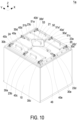
- FIG. 10 is a perspective structural view illustrating an immersion cooling system with an airtight link latch cover structure operated in the closed state according to a second embodiment of the present disclosure.
- the structures, elements and functions of the immersion cooling system 1a with the airtight link latch cover structure are similar to those of the immersion cooling system 1 with the airtight link latch cover structure of FIG. 1 to FIG. 9 , and are not redundantly described herein.
- the immersion cooling system 1a with the airtight link latch cover structure further includes a plurality of latches 40a ⁇ 40e, 40a' ⁇ 40c' and a plurality of fixing components 30a ⁇ 30e, 30a'-30c', which are cooperated in pairs and disposed adjacent to the three fastening lateral sides 23b ⁇ 23d and the connection lateral side 23a, respectively.
- the plurality of latches 40a' ⁇ 40c' and the plurality of fixing components 30a' ⁇ 30c' cooperated in pairs are disposed adjacent to the connection lateral side 23a to implement the connection between the connection lateral side 23a of the upper cover 20 and the box 10.
- the pairing of the latches 40a' ⁇ 40c' and the fixing components 30a' ⁇ 30c' is the same as the pairing of the latches 40a ⁇ 40c and the fixing components 30a ⁇ 30c.
- the slidable connection between the latch 40a' ⁇ 40c' and to the crossbar 51a' corresponding thereto is also the same as the slidable connection between the latches 40a ⁇ 40c and the crossbars 51a ⁇ 51c corresponding thereto, and not redundantly described herein.
- the operation of unlocking the upper cover 20 and detaching the upper cover 20 from the opening 11 can be completed in a single direction (i.e., the Z axial direction).
- the arrangements and the numbers of the latches 40a ⁇ 40e, 40a'-40c', the fixing components 30a ⁇ 30e, 30a' ⁇ 30c' and the crossbars 51a ⁇ 51c, 51a' are not limited to the illustrated embodiments, and not redundantly described hereafter.
- the present disclosure provides an immersion cooling system with an airtight link latch cover structure having handles combined with a link module to synchronously drive a plurality of latches in an open operation or a close operation, so that the convenience of operation is increased, and the airtight effect is achieved when the upper cover is locked. Consequently, the leakage of evaporated gas is avoided, the loss of dielectric liquid is decreased, and the purpose of cost saving is achieved.
- the airtight link latch cover structure is disposed over an upper space of the immersion cooling system by combining a link module with a plurality of latches.
- the plurality of latches disposed on the upper cover are arranged adjacent to the at least three fastening lateral sides of the upper cover, and spatially corresponding to a plurality fixing components disposed adjacent to an outer perimeter of the opening of the box, so that the plurality of latches are cooperated with the plurality of fixing components in pairs.
- the link module allows to synchronously drive each handle of the latches disposed adjacent to the different fastening lateral sides of the same fastening lateral side through the link elements, and the user only needs to perform the operations of sealing, unlocking and opening the upper cover in the space above the upper cover.
- each scroll-wheel of the plurality of latches rolls back into the respective housing base along the direction away from the corresponding limiting surface, and does not interfere with the corresponding fixing component.
- the link module and the plurality of latches are all within the vertical projection range of the upper cover, and it allows the upper cover to be separated from the opening of the box for the user to perform the maintenance work or replace electronic components in the box. The opening and closing operations are simplified effectively, and the convenience of operation is improved.
- the plurality of latches and the plurality of fixing components cooperated in pairs are not limited to being disposed adjacent to the three fastening lateral sides of the upper cover.
- the hinge connection between the connecting side of the upper cover and the box can also be replaced by the latching method of the latch and the fixing component in pair, so that the operation of unlocking and opening the upper cover can be realized in a single direction (up or down).
- the number and the arrangement of the plurality of latches are adjustable according to the airtight requirements, so as to increase the convenience of operation and maintain the airtight effect when the upper cover is locked. Consequently, the leakage of evaporated gas is avoided, the loss of dielectric liquid is decreased, and the purpose of cost saving is achieved.
Landscapes
- Engineering & Computer Science (AREA)
- Microelectronics & Electronic Packaging (AREA)
- Physics & Mathematics (AREA)
- Thermal Sciences (AREA)
- Casings For Electric Apparatus (AREA)
- Cooling Or The Like Of Electrical Apparatus (AREA)
- Cooling Or The Like Of Semiconductors Or Solid State Devices (AREA)
Abstract
An immersion cooling system (1, 1a) is provided. The immersion cooling system (1, 1a) includes a box (10), an upper cover (20), plural fixing components (30a, 30b, 30c, 30d, 30e, 30a', 30b', 30c'), plural latches (40a, 40b, 40c, 40d, 40e, 40a', 40b', 40c') and a link module (50). The box (10) has an opening (11) upwardly. The upper cover (20) covers the opening (11). The fixing components (30a, 30b, 30c, 30d, 30e, 30a', 30b', 30c') are disposed on the box (10) and arranged adjacent to the outer perimeter of the opening (11). The latches (40a, 40b, 40c, 40d, 40e, 40a', 40b', 40c') corresponding to the fixing components (30a, 30b, 30c, 30d, 30e, 30a', 30b', 30c') are disposed on the upper cover (20). The link module (50) includes plural crossbars (51a, 51b, 51c) corresponding to the latches (40a, 40b, 40c, 40d, 40e, 40a', 40b', 40c'). The link module (50) moves downwardly close to the upper cover (20), scroll-wheel (43) of the latches (40a, 40b, 40c, 40d, 40e, 40a', 40b', 40c') roll along limiting surfaces (31) of corresponding fixing components (30a, 30b, 30c, 30d, 30e, 30a', 30b', 30c') and press against the upper cover (20), the upper cover (20) closes the opening (11) to form an airtight space. The link module (50) moves upwardly away from the upper cover (20), the scroll-wheels (43) are separated away from the limiting surfaces (31) of corresponding fixing components (30a, 30b, 30c, 30d, 30e, 30a', 30b', 30c'), allows the upper cover (20) to separate from the opening (11).
Description
- The present disclosure relates to an immersion cooling system, and more particularly to an immersion cooling system with an airtight link latch cover structure having handles combined with a link module to synchronously drive a plurality of latches in an open operation or a close operation, so that the convenience of operation is increased, and the airtight effect is achieved when the upper cover is locked.
- A dual-phase immersion cooling system is to immerse a heat-generating electronic components directly in a dielectric liquid. The latent heat phase change of the dielectric served as the working liquid is utilized to dissipate the heat during heating and boiling vaporization. In order to avoid the escape of the dielectric liquid after vaporization, the container used in the system must be airtight. Furthermore, the container should also allow the user to replace the electronic components.
- Usually, the air-tightness of the conventional immersion cooling system is realized through screw locking. Although it has a good sealing effect, it is inconvenient to operate and the man-hours for maintenance will be increased. In addition, the hasp design is also commonly used in the air-tightness of the immersion cooling system. It is easy to operate, but there must be enough space on the outside for operating and performing the opening or closing action stroke.
- Therefore, there is a need of providing an immersion cooling system with an airtight link latch cover structure having handles combined with a link module to synchronously drive a plurality of latches in an open operation or a close operation, so as to increase the convenience of operation, achieve the airtight effect when the upper cover is locked, and obviate the drawbacks encountered by the prior arts.
- An object of the present disclosure is to provide an immersion cooling system with an airtight link latch cover structure having handles combined with a link module to synchronously drive a plurality of latches in an open operation or a close operation, so that the convenience of operation is increased, and the airtight effect is achieved when the upper cover is locked. Consequently, the leakage of evaporated gas is avoided, the loss of dielectric liquid is decreased, and the purpose of cost saving is achieved.
- Another object of the present disclosure is to provide an immersion cooling system with an airtight link latch cover structure. The airtight link latch cover structure is disposed over an upper space of the immersion cooling system by combining a link module with a plurality of latches. The plurality of latches disposed on the upper cover are arranged adjacent to the at least three fastening lateral sides of the upper cover, and spatially corresponding to a plurality of fixing components disposed adjacent to an outer perimeter of the opening of the box, so that the plurality of latches are cooperated with the plurality of fixing components in pairs. The link module allows to synchronously drive each handle of the latches disposed adjacent to the different fastening lateral sides of the same fastening lateral side through the link elements, and the user only needs to perform the operations of sealing, unlocking and opening the upper cover in the space above the upper cover. When the user presses down the link module to synchronously drive the plurality of handles of the plurality of latches, only the scroll-wheels pivotally connected to the front ends of the sliding rods of the plurality of latches exceed the vertical projection range of the upper cover and interfere with the corresponding ones of the plurality of fixing components. In detail, when the scroll-wheels are driven by the sliding rods to move towards the corresponding ones of the fixing components, each scroll-wheel rolling along the corresponding limiting surface of the fixing components is pressed against the corresponding limiting surface to push the upper cover downwardly, so that the plurality of latches are pushed downwardly at the same time, and the sealing strip between the upper cover and the box is compressed to achieve the effect of sealing the opening. Consequently, it completely prevents the dielectric liquid in the box from evaporating and leaking through the opening, the loss of the dielectric liquid is decreased, and the purpose of cost saving is achieved. On the other hand, when the user pulls up the link module to synchronously drive the plurality of handles of the plurality of latches, each scroll-wheel of the plurality of latches rolls back into the respective housing base along the direction away from the corresponding limiting surface, and does not interfere with the corresponding fixing component. The link module and the plurality of latches are all within the vertical projection range of the upper cover, and it allows the upper cover to be separated from the opening of the box for the user to perform the maintenance work or replace electronic components in the box. The opening and closing operations are simplified effectively, and the convenience of operation is improved. In addition, the plurality of latches and the plurality of fixing components cooperated in pairs are not limited to being disposed adjacent to the three fastening lateral sides of the upper cover. The hinge connection between the connecting side of the upper cover and the box can also be replaced by the latching method of the latch and the fixing component in pair, so that the operation of unlocking and opening the upper cover can be realized in a single direction (up or down). In other words, when the upper cover seals the opening of the box in the immersion cooling system through the airtight link latch cover structure, the number and the arrangement of the plurality of latches are adjustable according to the airtight requirements, so as to increase the convenience of operation and maintain the airtight effect when the upper cover is locked. Consequently, the leakage of evaporated gas is avoided, the loss of dielectric liquid is decreased, and the purpose of cost saving is achieved.
- In accordance with an aspect of the present disclosure, an immersion cooling system with an airtight link latch cover structure is provided and includes a box, an upper cover, a plurality of fixing components, a plurality of latches and a link module. The box includes an opening facing upwards. The upper cover includes a connection lateral side, three fastening lateral sides, a top surface and a bottom surface, wherein the connection lateral side and the three fastening lateral sides are connected between the top surface and the bottom surface, the connection lateral side is connected to an edge of the opening, and the bottom surface covers the opening to form an airtight space. The plurality of fixing components are spatially corresponding to the three fastening lateral sides and disposed adjacent to an outer perimeter of the opening, wherein each of the plurality of fixing components includes a limiting surface, and the limiting surfaces have a height greater than that of the top surface when the bottom surface covers the opening. The plurality of latches are spatially corresponding to the plurality of fixing components and disposed on the top surface of the upper cover. Each of the plurality of latches includes a housing base, a sliding rod, a scroll-wheel and a handle. The housing base is disposed on the upper cover, faces a corresponding one of the plurality of fixing components, and is arranged adjacent to one of the three fastening lateral sides. The sliding rod is slidably disposed on the housing base, wherein a front end of the sliding rod faces the corresponding one of the plurality of fixing components. The scroll-wheel is pivotally connected to the front end of the sliding rod. The handle is pivotally connected to the housing base and includes an end abutting against the sliding rod, wherein another end of the handle is operated to drive the sliding rod to slide in a horizontal direction. The link module is spatially arranged above the top surface of the upper cover, and includes a plurality of crossbars corresponding to the plurality of handles of the plurality of latches, wherein the plurality of handles include a plurality of connection ends slidably connected to corresponding ones of the plurality of crossbars, respectively. When the link module is moved down toward the top surface of the upper cover, the plurality of crossbars drive the plurality of handles to simultaneously drive the plurality of sliding rods to slide horizontally toward the corresponding plurality of fixing components, and the plurality of scroll-wheels roll along and abut against the limiting surfaces of the plurality of fixing components corresponding thereto, so that the bottom surface of the upper cover closely fits the opening to form the airtight space. When the link module is moved up away from the top surface of the upper cover, the plurality of crossbars drive the plurality of handles to simultaneously drive the plurality of sliding rods to slide horizontally away from the corresponding plurality of fixing components, and the plurality of scroll-wheels move away from the limiting surfaces of the plurality of fixing components corresponding thereto, so that the bottom surface of the upper cover allows being separated from the opening.
- The above contents of the present disclosure will become more readily apparent to those ordinarily skilled in the art after reviewing the following detailed description and accompanying drawings, in which:
-
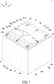
FIG. 1 is a perspective structural view illustrating an immersion cooling system with an airtight link latch cover structure operated in the closed state according to a first embodiment of the present disclosure; -
FIG. 2 is an enlarged view of the region P1 inFIG. 1 ; -
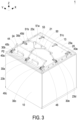
FIG. 3 is a perspective structural view illustrating the immersion cooling system with the airtight link latch cover structure operated in the unlocked state according to the first embodiment of the present disclosure; -
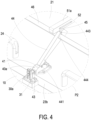
FIG. 4 is an enlarged view of the region P2 inFIG. 3 ; -
FIG. 5 is a perspective structural view illustrating the immersion cooling system with the airtight link latch cover structure operated in the opening state of the upper cover according to the first embodiment of the present disclosure; -
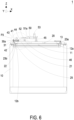
FIG. 6 is a perspective structural view illustrating the immersion cooling system with the airtight link latch cover structure operated in the closed state according to the first embodiment of the present disclosure; -
FIG. 7 is an enlarged view of the region P3 inFIG. 6 ; -
FIG. 8 is a cross sectional view illustrating the immersion cooling system with the airtight link latch cover structure operated in the unlocked state according to the first embodiment of the present disclosure; -
FIG. 9 is an enlarged view of the region P4 inFIG. 7 ; and -
FIG. 10 is a perspective structural view illustrating an immersion cooling system with an airtight link latch cover structure operated in the closed state according to a second embodiment of the present disclosure. - The present disclosure will now be described more specifically with reference to the following embodiments. It is to be noted that the following descriptions of preferred embodiments of this disclosure are presented herein for purpose of illustration and description only. It is not intended to be exhaustive or to be limited to the precise form disclosed. For example, the formation of a first feature over or on a second feature in the description that follows may include embodiments in which the first and second features are formed in direct contact, and may also include embodiments in which additional features may be formed between the first and second features, such that the first and second features may not be in direct contact. In addition, the present disclosure may repeat reference numerals and/or letters in the various examples. This repetition is for the purpose of simplicity and clarity and does not in itself dictate a relationship between the various embodiments and/or configurations discussed. Further, spatially relative terms, such as "upper," "lower," "top," "bottom" and the like, may be used herein for ease of description to describe one element or feature's relationship to another element(s) or feature(s) as illustrated in the figures. The spatially relative terms are intended to encompass different orientations of the device in use or operation in addition to the orientation depicted in the figures. In addition, although the "first," "second," "third," and the like terms in the claims be used to describe the various elements can be appreciated, these elements should not be limited by these terms, and these elements are described in the respective embodiments are used to express the different reference numerals, these terms are only used to distinguish one element from another element. For example, a first element could be termed a second element, and, similarly, a second element could be termed a first element, without departing from the scope of example embodiments.
- Please refer to
FIG. 1 to FIG. 9 . An immersion cooling system with an airtight link latch cover structure is illustrated according to a first embodiment of the present disclosure. In the embodiment, theimmersion cooling system 1 with an airtight link latch cover structure is provided and includes abox 10, anupper cover 20, a plurality of fixingcomponents 30a∼30e, a plurality oflatches 40a∼40e and alink module 50. Preferably but not exclusively, theimmersion cooling system 1 is applied to the cooling of electronic components. Thebox 10 includes anopening 11. The dielectric liquid for cooling and the electronic components(not shown) required to be cooled are contained in the interior of thebox 10. Preferably but not exclusively, theopening 11 of thebox 10 faces upwards, for example, toward the Z axial direction for users to perform the replacement or maintenance operations. When theimmersion cooling system 1 performs the cooling operation, theopening 11 needs to be closed. In the embodiment, theupper cover 20 includes a connectionlateral side 23a, three fasteninglateral sides 23b∼23d, atop surface 21 and abottom surface 22. The connectionlateral side 23a and the three fasteninglateral sides 23b∼23d are connected between thetop surface 21 and thebottom surface 22 to form a rectangle. In the embodiment, the connectionlateral side 23a of theupper cover 20 is connected to anedge 12a of theopening 11 through threepivot elements 13. Moreover, the three fasteninglateral sides 23b∼23d of theupper cover 20 are fastened to the other threeedges 12b∼12d of theopening 11 through the plurality oflatches 40a~40e and the plurality of fixingcomponents 30a∼30e cooperated in pairs, so that thebottom surface 22 of theupper cover 20 covers theopening 11 to form an airtight space in thebox 10. Certainly, the connection between the connectionlateral side 23a of theupper cover 20 and theedge 12a of theopening 11 is not limited to the pivot connection or the hasp connection. In the embodiment, the plurality of fixingcomponents 30a∼30e are disposed on theupper cover 20 and disposed adjacent to an outer perimeter of theopening 11. Furthermore, the plurality of fixingcomponents 30a∼30e are spatially corresponding to the three fasteninglateral sides 23b∼23d of theupper cover 20. In the embodiment, each of the plurality of fixingcomponents 30a∼30e includes a limitingsurface 31. Moreover, when thebottom surface 22 of theupper cover 20 covers theopening 11, the limitingsurfaces 31 of the fixingcomponents 30a∼30e have a height in the Z axial direction greater than a height of thetop surface 21 in the Z axial direction (Referring toFIG. 7 ). It should be noted that the plurality of limitingsurfaces 31 of the plurality of fixingcomponents 30a∼30e are fixed, for example, by the adjusting screws, and the height of the limitingsurfaces 31 in the Z axial direction is adjustable according to the practical requirements, and the present disclosure is not limited thereto. In the embodiment, the plurality oflatches 40a∼40e are spatially corresponding to the plurality of fixingcomponents 30a∼30e and disposed on thetop surface 21 of theupper cover 20. Thelink module 50 is spatially arranged above thetop surface 21 of theupper cover 20, and includes a plurality ofcrossbars 51a~51c corresponding to the plurality oflatches 40a∼40e. Preferably but not exclusively, the plurality ofcrossbars 51a~51c are movably connected to the plurality oflatches 40a∼40e. When thelink module 50 is operated to attach to thetop surface 21 of theupper cover 20 and move downwards (along the Z axial direction), the plurality oflatches 40a~40e interfere with the corresponding ones of the plurality of fixingcomponents 30a∼30e, so that thebottom surface 22 of theupper cover 20 closely fits theopening 11 to form the airtight space. On the contrary, when thelink module 50 is operated to move up away from thetop surface 21 of theupper cover 20, the plurality oflatches 40a∼40e and the corresponding plurality of fixingcomponents 30a∼30e do not interfere with each other, and theupper cover 20 can be disengaged from theopening 11. It facilitates the user to replace or maintain the electronic components or the coolant in thebox 10, as shown inFIG. 5 . - Notably, in the embodiment, the plurality of
latches 40a~40e and the plurality of fixingcomponents 30a∼30e are cooperated in pairs. For ease of description, the actuation relationship between the plurality oflatches 40a∼40e and the plurality of fixingcomponents 30a∼30e is only represented by the actuation relationship between thelatch 40a and thefixing component 30a in some figures, but the present disclosure is not limited thereto. In the embodiment, each of the plurality oflatches 40a~40e includes ahousing base 41, a slidingrod 42, a scroll-wheel 43 and ahandle 44. Thehousing base 41 is disposed on theupper cover 20, faces a corresponding one of the plurality of fixingcomponents 30a∼30e, and is arranged adjacent to one of the three fasteninglateral sides 23b∼23d. For example, thehousing base 41 of thelatch 40a is corresponding to thefixing component 30a, and disposed adjacent to the middle section of the oppositefastening lateral side 23b, and away from the connectionlateral side 23a. In the embodiment, the slidingrod 42 is slidably disposed on thehousing base 41. When thelink module 50 is operated to attach to thetop surface 21 of theupper cover 20, the slidingrod 42 can be driven to slide horizontally on the XY plane. For example, one moves along the X axial direction or along the Y axial direction. It depends on the location. In the embodiment, afront end 421 of the slidingrod 42 faces the corresponding one of the plurality of fixingcomponents 30a∼30e. For example, thefront end 421 of the slidingrod 42 of thelatch 40a faces thecorresponding fixing component 30a. In the embodiment, the scroll-wheel 43 is pivotally connected to thefront end 421 of the slidingrod 42, and spatially corresponding to the limitingsurface 31 of the corresponding one of the plurality of fixingcomponents 30a∼30e. In the embodiment, thehandle 44 is pivotally connected to thehousing base 41 and includes an end abutting against the slidingrod 42. When another end of thehandle 44 is operated to drive the slidingrod 42, the corresponding slidingrod 42 is driven to slide in a horizontal direction on the XY plane. For example, one moves along the X axial direction or along the Y axial direction. It depends on the location. - For each of the plurality of
latches 40a∼40e, taking thelatch 40a as an example, the slidingrod 42 further includes a firstabutting element 422 and a secondabutting element 423 accommodated within thehousing base 41. The firstabutting element 422 is located between thefront end 421 and the secondabutting element 423. In addition, thehandle 44 is pivotally arranged on thehousing base 41 through apivot shaft 441, and thehandle 44 further includes anacting end 442 and aconnection end 443. The actingend 442 is accommodated with in thehousing base 41. Moreover, the actingend 442 is located between the firstabutting element 422 and the secondabutting element 423, and theconnection end 443 is located outside thehousing base 41. In the embodiment, theconnection end 443 of thehandle 44 is slidably connected to anoval slot 52 of thecorresponding crossbar 51a through alink element 45. Preferably but not exclusively, when thehandle 44 is operated to move down and abut against the firstabutting element 422, thefront end 421 of the slidingrod 42 to protrude out of thehousing base 41 on the XY plane. Preferably but not exclusively, when thehandle 44 is operated to move up and abut against the secondabutting element 423, thefront end 421 of the slidingrod 42 is driven to slide back into thehousing base 41 on the XY plane. Preferably but not exclusively, in the embodiment, the firstabutting element 422 is a transverse cylinder perpendicular to theacting end 442 of thehandle 44. Moreover, the actingend 442 of thehandle 44 further includes an arc surface correspondingly abutting against the transverse cylinder on the firstabutting element 422. If facilitates thefront end 421 of the slidingrod 42 to be pushed out of thehousing base 41 smoothly on the XY plane when the operatinghandle 44 is operated to rotate downward. In addition, aspring 47 is further sleeved on the slidingrod 42. Preferably but not exclusively, thespring 47 is arranged between the secondabutting element 423 of the slidingrod 42 and thehousing base 41 corresponding thereto. It facilitates theacting end 442 of thehandle 44 to push the slidingrod 42 with the elastic force of thespring 47. Certainly, the manner in which thehandle 44 is operated to rotate and drive the slidingrod 42 to make the slidingrod 42 slide horizontally is adjustable according to the practical requirements. The present disclosure is not limited thereto. - In the embodiment, the
link module 50 is spatially arranged above thetop surface 21 of theupper cover 20, and includes a plurality ofcrossbars 51a~51c corresponding to the plurality ofhandles 44 of the plurality oflatches 40a∼40e. Preferably but not exclusively, in the embodiment, thelink module 50 includes threecrossbars 51a~51c, which are spatially corresponding to the middle sections of the three fasteninglateral sides 23b∼23d. Therefore, the threecrossbars 51a∼51c are arranged in a T shape. In the embodiment, at least three of the plurality oflatches 40a~40e, such as thelatch 40a, thelatch 40d and thelatch 40e, are disposed adjacent to three middle sections of the three fasteninglateral sides 23b∼23d, respectively. Moreover, the plurality connection ends 442 of thehandles 44 of thelatches oval slots 52 of thecorresponding crossbars 51a~51c through alink element 45, respectively. In this way, the plurality ofhandles 44 of thelatches link module 50 in one operation. - In addition, the plurality of fixing
components 30a∼30e and the plurality oflatches 40a∼40e cooperated in pairs have at least one pair, for example the pair of thefixing component 30a and thelatch 40a, disposed adjacent to the middle section of the oppositefastening lateral side 23b, and have at least two others pairs, for example the pair of thefixing component 30b and thelatch 40b and the pair of the fixingcomponent 30c and thelatch 40c, disposed adjacent to two ends of the oppositefastening lateral side 23b, respectively. That is, at least three pairs of fixingcomponents 30a∼30c and thelatches 40a∼40c are disposed adjacent to the oppositefastening lateral side 23b. In the embodiment, each of the plurality ofhandles 44 of the plurality oflatches 40a∼40e has acommunication opening 444 disposed adjacent to theconnection end 443 of therespective handle 44. Since thelatches 40a∼40c are arranged along the oppositefastening lateral side 23b, the plurality oflatches 40a∼40c disposed adjacent to the oppositefastening lateral side 23b can be connected to each other with aconnection rod 46 passing through the plurality ofcommunication openings 444. In this way, when thecrossbar 51a of thelink module 50 drives thehandle 44 of thelatch 40a, thehandles 44 of thelatch 40b and thelatch 40c connected through theconnection rod 46 are also driven synchronously. Thereby, thelink module 50 can drive thehandles 44 of the plurality oflatches 40a∼40e to perform synchronous operations. - In the embodiment, the plurality of connection ends 443 of the plurality of
handles 44 of the plurality oflatches 40a∼40e are slidably connected to the corresponding ones of the plurality ofcrossbars 51a∼51c in the aforementioned manner. Notably, the plurality oflatches 40a∼40e and thelink module 50 are constructed in the space above thetop surface 21 of theupper cover 20, and the plurality ofhousing bases 41, the plurality ofhandles 44 of thelatches 40a∼40e and thelink module 50 have a vertical projection ranged with a vertical projection of theupper cover 20. This design has advantage of saving the assembling and operating space of theimmersion cooling system 1. When thelink module 50 is operated to move downward and attach to thetop surface 21 of theupper cover 20, the plurality ofcrossbars 51a~51c drive the plurality ofhandles 44 to simultaneously drive the plurality of slidingrods 42 to slide horizontally toward the corresponding plurality of fixingcomponents 30a-30e. For example, the slidingrods 42 of thelatches 40a-40c protrude horizontally from the fasteninglateral side 23b along the reverse X axial direction, the slidingrod 42 of thelatch 40d protrudes horizontally from the fasteninglateral side 23c along the Y axial direction, and the slidingrod 42 of thelatch 40e protrudes horizontally from the fasteninglateral side 23d along the reverse Y axial direction. At this time, the plurality of scroll-wheels 43 of the plurality oflatches 40a~40e interfere with the plurality of limitingsurfaces 31 of the corresponding plurality of fixingcomponents 30a∼30e in a vertical viewing direction (i.e., the Z axial direction). The plurality of scroll-wheels 43 of the plurality oflatches 40a~40e roll along and abut against the limitingsurfaces 31 of the plurality of fixingcomponents 30a∼30e corresponding thereto, so that thebottom surface 22 of theupper cover 20 closely fits theopening 11 of thebox 10 to form the airtight space. On the contrary, when the user operates thelink module 50 to be separated from thetop surface 21 of theupper cover 20 and move upwards, the plurality ofcrossbars 51a∼51c drive the plurality ofhandles 44 to simultaneously drive the plurality of slidingrods 42 to slide horizontally away from the corresponding plurality of fixingcomponents 30a∼30e in one operation, and the plurality of scroll-wheels 43 of the plurality oflatches 40a∼40e move away from the limitingsurfaces 31 of the plurality of fixingcomponents 30a∼30e corresponding thereto. In that, the plurality oflatches 40a∼40e and thelink module 50 have the vertical projection to be restored and ranged within the vertical projection of theupper cover 20. Since the plurality oflatches 40a-40e and the corresponding plurality of fixingcomponents 30a∼30e do not interfere with each other, it allows to separate thebottom surface 22 of theupper cover 20 from theopening 11, so that the user can perform the replacement or maintenance operations to replace or maintain the electronic components or the coolant. - Notably, the plurality of fixing
components 30a∼30e and the plurality oflatches 40a∼40e are cooperated in pairs, and the arrangement and the number of the pairs disposed adjacent to the three fasteninglateral sides 23b∼23d are adjustable according to the practical requirements. Similarly, the link relationship among the plurality oflatches 40a∼40e and the plurality ofcrossbars 51a~51c of thelink module 50 is adjustable according to the practical requirements. In an embodiment, thelatch 40b and thelatch 40c are omitted, so that the number of the plurality oflatches lateral sides 23b∼23d is equal to each other. That is, the plurality oflatches lateral sides 23b∼23d, respectively, and each of thelatches oval slots 52 of thecorresponding crossbars 51a∼51c through thelink elements 45, respectively. In other embodiment, the number of the plurality of latches disposed adjacent to each of the three fasteninglateral sides 23b∼23d is the same and equal to N, N is an integer, and N≧1. The N latches are slidably connected to the N crossbars. Certainly, the present disclosure is not limited thereto. Moreover, in an embodiment, one of the three fasteninglateral sides 23b∼23d is an oppositefastening lateral side 23b disposed opposite to the connectionlateral side 23a, the number of the plurality of latches disposed adjacent to the oppositefastening lateral side 23b is equal to 3, but different from the numbers of latches disposed on the other fasteninglateral sides fastening lateral side 23b is equal to 2M+1, M is an integer, and M ≧1. Certainly, the numbers and the arrangements of the fixingcomponents 30a∼30e, thelatches 40a∼40e and thecrossbars 51a~51c are adjustable according to the practical requirements, and the present disclosure is not limited thereto. - In the embodiment, the
link module 50 further includes a holdinghandle 53 arranged at a place where the plurality ofcrossbars 51a∼51c are converged. It facilitates the user to exert force to move thelink module 50 up and down, and perform the opening and closing operations through the plurality ofcrossbars 51a~51c synchronously driving the plurality oflatches 40a-40e. Moreover, in the embodiment, theupper cover 20 further includes at least one carryinghandle 24 disposed adjacent to one of the three fasteninglateral sides 23b∼23d that is relatively far away from the connectionlateral side 23a. That is, the at least one carryinghandle 24 is disposed adjacent to the oppositefastening lateral side 23b, for the user to further open theupper cover 20 when the plurality oflatches 40a∼40e are in the unlocked state, as shown inFIG. 5 . Moreover, in the embodiment, theupper cover 20 includes two carryinghandles 24 symmetrically disposed on two opposite laterals of the middle section of the oppositefastening lateral side 23b. In other embodiments, the arrangements and the numbers of the holdinghandle 53 of thelink module 50 or the carrying handles 24 of the upper covers 20 are adjustable according to the practical requirements, and the present disclosure is not limited thereto. In the embodiment, theupper cover 20 further includes a sealingstrip 25 disposed on thebottom surface 22 and spatially corresponding to the outer perimeter of theopening 11 of thebox 10. When the plurality oflatches 40a∼40e interfere with the corresponding ones of the plurality of fixingcomponents 30a∼30e and push theupper cover 20 downwardly, the sealingstrip 25 between theupper cover 20 and thebox 10 is further compressed by theupper cover 20, so as to enhance the effect of sealing theopening 11. Certainly, the present disclosure is not limited thereto. -
FIG. 10 is a perspective structural view illustrating an immersion cooling system with an airtight link latch cover structure operated in the closed state according to a second embodiment of the present disclosure. In the embodiment, the structures, elements and functions of theimmersion cooling system 1a with the airtight link latch cover structure are similar to those of theimmersion cooling system 1 with the airtight link latch cover structure ofFIG. 1 to FIG. 9 , and are not redundantly described herein. In the embodiment, theimmersion cooling system 1a with the airtight link latch cover structure further includes a plurality oflatches 40a∼40e, 40a'∼40c' and a plurality of fixingcomponents 30a∼30e, 30a'-30c', which are cooperated in pairs and disposed adjacent to the three fasteninglateral sides 23b∼23d and the connectionlateral side 23a, respectively. Different form the pivot connection implemented through thepivot elements 13 between the connectionlateral side 23a of theupper cover 20 and thebox 10 in the first embodiment, in the embodiment, the plurality oflatches 40a'∼40c' and the plurality of fixingcomponents 30a'∼30c' cooperated in pairs are disposed adjacent to the connectionlateral side 23a to implement the connection between the connectionlateral side 23a of theupper cover 20 and thebox 10. Preferably but not exclusively, the pairing of thelatches 40a'∼40c' and the fixingcomponents 30a'~30c' is the same as the pairing of thelatches 40a∼40c and the fixingcomponents 30a∼30c. Moreover, the slidable connection between thelatch 40a'∼40c' and to thecrossbar 51a' corresponding thereto is also the same as the slidable connection between thelatches 40a∼40c and thecrossbars 51a~51c corresponding thereto, and not redundantly described herein. Notably, when the three fasteninglateral sides 23b∼23d and the connectionlateral side 23a of theupper cover 20 are connected to thebox 10 through thelatches 40a∼40e, 40a'∼40c' and the fixingcomponents 30a∼30e, 30a'∼30c' cooperated in pairs to realize the locking function, the operation of unlocking theupper cover 20 and detaching theupper cover 20 from theopening 11 can be completed in a single direction (i.e., the Z axial direction). Certainly, the arrangements and the numbers of thelatches 40a∼40e, 40a'-40c', the fixingcomponents 30a∼30e, 30a'~30c' and thecrossbars 51a∼51c, 51a' are not limited to the illustrated embodiments, and not redundantly described hereafter. - In summary, the present disclosure provides an immersion cooling system with an airtight link latch cover structure having handles combined with a link module to synchronously drive a plurality of latches in an open operation or a close operation, so that the convenience of operation is increased, and the airtight effect is achieved when the upper cover is locked. Consequently, the leakage of evaporated gas is avoided, the loss of dielectric liquid is decreased, and the purpose of cost saving is achieved. In the present disclosure, the airtight link latch cover structure is disposed over an upper space of the immersion cooling system by combining a link module with a plurality of latches. The plurality of latches disposed on the upper cover are arranged adjacent to the at least three fastening lateral sides of the upper cover, and spatially corresponding to a plurality fixing components disposed adjacent to an outer perimeter of the opening of the box, so that the plurality of latches are cooperated with the plurality of fixing components in pairs. The link module allows to synchronously drive each handle of the latches disposed adjacent to the different fastening lateral sides of the same fastening lateral side through the link elements, and the user only needs to perform the operations of sealing, unlocking and opening the upper cover in the space above the upper cover. When the user presses down the link module to synchronously drive the plurality of handles of the plurality of latches, only the scroll-wheels pivotally connected to the front ends of the sliding rods of the plurality of latches exceed the vertical projection range of the upper cover and interfere with the corresponding ones of the plurality of fixing components. In detail, when the scroll-wheels are driven by the sliding rods to move towards the corresponding ones of the fixing components, each scroll-wheel rolling along the corresponding limiting surface of the fixing components is pressed against the corresponding limiting surface to push the upper cover downwardly, so that the plurality of latches are pushed downwardly at the same time, and the sealing strip between the upper cover and the box is compressed to achieve the effect of sealing the opening. Consequently, it completely prevents the dielectric liquid in the box from evaporating and leaking through the opening, the loss of the dielectric liquid is decreased, and the purpose of cost saving is achieved. On the other hand, when the user pulls up the link module to synchronously drive the plurality of handles of the plurality of latches, each scroll-wheel of the plurality of latches rolls back into the respective housing base along the direction away from the corresponding limiting surface, and does not interfere with the corresponding fixing component. The link module and the plurality of latches are all within the vertical projection range of the upper cover, and it allows the upper cover to be separated from the opening of the box for the user to perform the maintenance work or replace electronic components in the box. The opening and closing operations are simplified effectively, and the convenience of operation is improved. In addition, the plurality of latches and the plurality of fixing components cooperated in pairs are not limited to being disposed adjacent to the three fastening lateral sides of the upper cover. The hinge connection between the connecting side of the upper cover and the box can also be replaced by the latching method of the latch and the fixing component in pair, so that the operation of unlocking and opening the upper cover can be realized in a single direction (up or down). In other words, when the upper cover seals the opening of the box in the immersion cooling system through the airtight link latch cover structure, the number and the arrangement of the plurality of latches are adjustable according to the airtight requirements, so as to increase the convenience of operation and maintain the airtight effect when the upper cover is locked. Consequently, the leakage of evaporated gas is avoided, the loss of dielectric liquid is decreased, and the purpose of cost saving is achieved.
Claims (15)
- An immersion cooling system (1, 1a) with an airtight link latch cover structure, characterized by comprising:a box (10) comprising an opening (11) facing upwards;an upper cover (20) comprising a connection lateral side (23a), three fastening lateral sides (23b, 23c, 23d), a top surface (21) and a bottom surface (22), wherein the connection lateral side (23a) and the three fastening lateral sides (23b, 23c, 23d) are connected between the top surface (21) and the bottom surface (22), the connection lateral side (23a) is connected to an edge (12a) of the opening (11), and the bottom surface (22) covers the opening (11) to form an airtight space;a plurality of fixing components (30a, 30b, 30c, 30d, 30e, 30a', 30b', 30c') spatially corresponding to the three fastening lateral sides (23b, 23c, 23d) and disposed adjacent to an outer perimeter of the opening (11), wherein each of the plurality of fixing components (30a, 30b, 30c, 30d, 30e, 30a', 30b', 30c') comprises a limiting surface (31), and the limiting surfaces (31) have a height greater than that of the top surface (21) when the bottom surface (22) covers the opening (11);a plurality of latches (40a, 40b, 40c, 40d, 40e, 40a', 40b', 40c') spatially corresponding to the plurality of fixing components (30a, 30b, 30c, 30d, 30e, 30a', 30b', 30c') and disposed on the top surface (21) of the upper cover (20), wherein each of the plurality of latches (40a, 40b, 40c, 40d, 40e, 40a', 40b', 40c') comprises:a housing base (41) disposed on the upper cover (20), facing a corresponding one of the plurality of fixing components (30a, 30b, 30c, 30d, 30e, 30a', 30b', 30c'), and arranged adjacent to one of the three fastening lateral sides (23b, 23c, 23d);a sliding rod (42) slidably disposed on the housing base (41), wherein a front end (421) of the sliding rod (42) faces the corresponding one of the plurality of fixing components (30a, 30b, 30c, 30d, 30e, 30a', 30b', 30c');a scroll-wheel (43) pivotally connected to the front end (421) of the sliding rod (42); anda handle (44) pivotally connected to the housing base (41) and comprising an end abutting against the sliding rod (42), wherein another end of the handle (44) is operated to drive the sliding rod (42) to slide in a horizontal direction; anda link module (50) spatially arranged above the top surface (21) of the upper cover (20), and comprising a plurality of crossbars (51a, 51b, 51c, 51a') corresponding to the plurality of handles (44) of the plurality of latches (40a, 40b, 40c, 40d, 40e, 40a', 40b', 40c'), wherein the plurality of handles (44) comprise a plurality of connection ends (443) slidably connected to corresponding ones of the plurality of crossbars (51a, 51b, 51c, 51a'), respectively;wherein when the link module (50) is moved down toward the top surface (21) of the upper cover (20), the plurality of crossbars (51a, 51b, 51c, 51a') drive the plurality of handles (44) to simultaneously drive the plurality of sliding rods (42) to slide horizontally toward the corresponding plurality of fixing components (30a, 30b, 30c, 30d, 30e, 30a', 30b', 30c'), and the plurality of scroll-wheels (43) roll along and abut against the limiting surfaces (31) of the plurality of fixing components (30a, 30b, 30c, 30d, 30e, 30a', 30b', 30c') corresponding thereto, so that the bottom surface (22) of the upper cover (20) closely fits the opening (11) to form the airtight space; orwhen the link module (50) is moved up away from the top surface (21) of the upper cover (20), the plurality of crossbars (51a, 51b, 51c, 51a') drive the plurality of handle (44) to simultaneously drive the plurality of sliding rods (42) to slide horizontally away from the corresponding plurality of fixing components (30a, 30b, 30c, 30d, 30e, 30a', 30b', 30c'), and the plurality of scroll-wheels (43) move away from the limiting surfaces (31) of the plurality of fixing components (30a, 30b, 30c, 30d, 30e, 30a', 30b', 30c') corresponding thereto, so that the bottom surface (22) of the upper cover (20) allows being separated from the opening (11).
- The immersion cooling system (1, 1a) with the airtight link latch cover structure according to claim 1, wherein the sliding rod (42) comprises a first abutting element (422) and a second abutting element (423) accommodated within the housing base (41), wherein the first abutting element (422) is located between the front end (421) and the second abutting element (423).
- The immersion cooling system (1, 1a) with the airtight link latch cover structure according to claim 2, wherein the handle (44) comprises an acting end (442), the acting end (442) is accommodated with in the housing base (41) and located between the first abutting element (422) and the second abutting element (423), and the connection end (443) is located outside the housing base (41).
- The immersion cooling system (1, 1a) with the airtight link latch cover structure according to claim 3, wherein the first abutting element (422) is a transverse cylinder perpendicular to the handle (44), and the acting end (442) of the handle (44) comprises an arc surface correspondingly abutting against the first abutting element (422).
- The immersion cooling system (1, 1a) with the airtight link latch cover structure according to claim 3, wherein each of the plurality of latches (40a, 40b, 40c, 40d, 40e, 40a', 40b', 40c') further comprises a spring (47) sleeved between the second abutting element (423) of the sliding rod (42) and the housing base (41) corresponding thereto.
- The immersion cooling system (1) with the airtight link latch cover structure according to claim 1, wherein the number of the plurality of latches (40a, 40b, 40c, 40d, 40e) disposed adjacent to each of the three fastening lateral sides (23b, 23c, 23d) is N, N is an integer, and N≧1.
- The immersion cooling system (1) with the airtight link latch cover structure according to claim 6, wherein one of the three fastening lateral sides (23b, 23c, 23d) is an opposite fastening lateral side (23b) disposed opposite to the connection lateral side (23a), the number of the plurality of latches (40a, 40b, 40c) disposed adjacent to the opposite fastening lateral side (23b) is 2M+1, M is an integer, and M≧1.
- The immersion cooling system (1) with the airtight link latch cover structure according to claim 7, wherein the plurality of latches (40a, 40b, 40c, 40d, 40e) and the plurality of fixing components (30a, 30b, 30c, 30d, 30e) cooperated in pairs have at least one pair thereof disposed adjacent to a middle section of the opposite fastening lateral side (23b), and have at least two others pairs thereof disposed adjacent to two ends of the opposite fastening lateral side (23b), respectively, wherein each of the plurality of handles (44) of the plurality of latches (40a, 40b, 40c, 40d, 40e) has a communication opening (444) disposed adjacent to the connection end (443) thereof, wherein the plurality of latches (40a, 40b, 40c) disposed adjacent to the opposite fastening lateral side (23b) are connected to each other with a connection rod (46) passing through the plurality of communication openings (444) wherein the latch (40a) disposed adjacent to the middle section of the opposite fastening lateral side (23b) is slidably connected to an oval slot (52) of the corresponding crossbar (51a) through a link element (45).
- The immersion cooling system (1) with the airtight link latch cover structure according to claim 1, wherein at least three of the plurality of latches (40a, 40d, 40e) are disposed adjacent to three middle sections of the three fastening lateral sides(23b, 23c, 23d), respectively, and each of the latches (40a, 40d, 40e) is slidably connected to an oval slot (52) of the corresponding crossbar (51a, 51b, 51c) through a link element (45), wherein the link module (50) includes three crossbars (51a, 51b, 51c) spatially corresponding to the middle sections of the three fastening lateral sides (23b, 23c, 23d), the three crossbars (51a, 51b, 51c) are arranged in a T shape, wherein the link module (50) further comprises a holding handle (53) arranged at a place where the plurality of crossbars (51a, 51b, 51c) are converged.
- The immersion cooling system (1, 1a) with the airtight link latch cover structure according to claim 1, wherein the plurality of housing bases (41) and the plurality of handles (44) of the plurality of latches (40a, 40b, 40c, 40d, 40e, 40a', 40b', 40c') and the link module 50 have a vertical projection ranged within a vertical projection of the upper cover (20).
- The immersion cooling system (1, 1a) with the airtight link latch cover structure according to claim 1, wherein when the link module (50) is moved down toward the top surface (21) of the upper cover (20), the plurality of scroll-wheels (43) of the plurality of latches (40a, 40b, 40c, 40d, 40e, 40a', 40b', 40c') interfere with the plurality of limiting surfaces (31) of the plurality of fixing component (30a, 30b, 30c, 30d, 30e, 30a', 30b', 30c') corresponding thereto in a vertical viewing direction.
- The immersion cooling system (1, 1a) with the airtight link latch cover structure according to claim 1, wherein each of the plurality crossbars (51a, 51b, 51c) of the link module (50) comprise an oval slot (52) connected to the connection end (443) of the handle (44) corresponding thereto through a link element (45).
- The immersion cooling system (1) with the airtight link latch cover structure according to claim 1, wherein the connection lateral side (23a) of the upper cover (20) is connected to the box (10) through a pivot element (13).
- The immersion cooling system (1, 1a) with the airtight link latch cover structure according to claim 13, wherein the upper cover (20) comprises at least one carrying handle (24) disposed adjacent to one of the three fastening lateral sides (23b) that is relatively far away from the connection lateral side (23a) , wherein the upper cover (20) further comprises a sealing strip (25) disposed on the bottom surface (22) and spatially corresponding to the outer perimeter of the opening (11) of the box (10).
- The immersion cooling system (1a) with the airtight link latch cover structure according to claim 1, wherein the plurality of fixing components (30a, 30b, 30c, 30d, 30e, 30a', 30b', 30c') are spatially corresponding to the connection lateral side (23a) and three fastening lateral sides (23b, 23c, 23d) of the upper cover (20) and disposed adjacent to the outer perimeter of the opening (11), wherein the plurality of latches (40a', 40b', 40c') and the plurality of fixing components (30a', 30b', 30c') cooperated in pairs have at least one pair thereof disposed adjacent to the connection lateral side (23a) and configured to connect the connection lateral side (23a) of the upper cover (20) and the box (10).
Applications Claiming Priority (1)
| Application Number | Priority Date | Filing Date | Title |
|---|---|---|---|
| TW112122292A TWI888849B (en) | 2023-06-15 | 2023-06-15 | Immersion cooling system with airtight link latch cover structure |
Publications (1)
| Publication Number | Publication Date |
|---|---|
| EP4478850A1 true EP4478850A1 (en) | 2024-12-18 |
Family
ID=87517424
Family Applications (1)
| Application Number | Title | Priority Date | Filing Date |
|---|---|---|---|
| EP23188031.1A Pending EP4478850A1 (en) | 2023-06-15 | 2023-07-27 | Immersion cooling system with airtight link latch cover structure |
Country Status (4)
| Country | Link |
|---|---|
| US (1) | US12369272B2 (en) |
| EP (1) | EP4478850A1 (en) |
| JP (1) | JP7571247B1 (en) |
| TW (1) | TWI888849B (en) |
Citations (5)
| Publication number | Priority date | Publication date | Assignee | Title |
|---|---|---|---|---|
| DE1958729U (en) * | 1967-01-25 | 1967-04-13 | Josef Wolf Eisen Und Metallwar | GAS-PROOF DOOR WITH LATCH AND LATCH LOCK. |
| US4467936A (en) * | 1981-07-15 | 1984-08-28 | American Sterilizer Company | Closure for a pressurized chamber |
| JPH02214147A (en) * | 1989-02-15 | 1990-08-27 | Fujitsu Ltd | Cooling apparatus |
| US20200337176A1 (en) * | 2019-04-22 | 2020-10-22 | Fujitsu Limited | Immersion tank and electronic apparatus |
| CN114945260A (en) * | 2021-02-17 | 2022-08-26 | 建准电机工业股份有限公司 | Immersion Cooling System |
Family Cites Families (28)
| Publication number | Priority date | Publication date | Assignee | Title |
|---|---|---|---|---|
| US1118435A (en) * | 1914-04-09 | 1914-11-24 | Mosler Safe Co | Fireproof safe. |
| US1808403A (en) * | 1928-04-19 | 1931-06-02 | Axel A Eklund | Latching means for removable crank case covers |
| US4005341A (en) * | 1975-12-17 | 1977-01-25 | R. E. Uptegraff Manufacturing Company | Casing construction for pole type dielectric containing transformer |
| JP3125615U (en) | 2006-06-20 | 2006-09-28 | 義之 後藤 | Pressure cooker lid lock device |
| USD663134S1 (en) * | 2011-04-20 | 2012-07-10 | Delta Electronics, Inc. | Cabinet |
| GB2584061B (en) | 2012-02-07 | 2021-03-03 | Southco | Lever actuated compression latch |
| US9049800B2 (en) * | 2013-02-01 | 2015-06-02 | Dell Products L.P. | Immersion server, immersion server drawer, and rack-mountable immersion server drawer-based cabinet |
| US9328964B2 (en) * | 2013-02-01 | 2016-05-03 | Dell Products, L.P. | Partitioned, rotating condenser units to enable servicing of submerged it equipment positioned beneath a vapor condenser without interrupting a vaporization-condensation cycling of the remaining immersion cooling system |
| US9759451B2 (en) | 2013-11-22 | 2017-09-12 | Thermo Fisher Scientific (Asheville) Llc | Recirculating bath |
| US9801302B2 (en) * | 2015-07-17 | 2017-10-24 | Delta Electronics, Inc. | Equipment cabinet and slidable-and-rotatable rack assembly thereof |
| TWI563161B (en) * | 2015-10-08 | 2016-12-21 | Delta Electronics Inc | A door with hiding locks and a container having the door |
| CN105804539B (en) | 2016-05-03 | 2018-04-17 | 胡圣伟 | Closed guard gate is with monolever linkage lock |
| US10874036B2 (en) * | 2018-10-08 | 2020-12-22 | Delta Electronics, Inc. | Cabinet and electronic device |
| US10737847B1 (en) * | 2019-02-12 | 2020-08-11 | Free-Free(USA) Inc | Cover structure of sealed can |
| WO2020178579A1 (en) | 2019-03-05 | 2020-09-10 | Iceotope Group Limited | Cooling module and cooling module rack |
| CN210085655U (en) | 2019-06-03 | 2020-02-18 | 常德经纬摇架科技有限公司 | Semi-pressure release mechanism of spring cradle |
| TWI756618B (en) * | 2020-01-15 | 2022-03-01 | 緯穎科技服務股份有限公司 | Immersion cooling apparatus |
| US12409330B2 (en) * | 2020-08-27 | 2025-09-09 | Wiwynn Corporation | Airtight device and feedthrough module |
| TWI731778B (en) * | 2020-08-27 | 2021-06-21 | 緯穎科技服務股份有限公司 | Liftable hinge mechanism and related airtight device for preventing gaseous matter from leakage |
| CN112261825A (en) | 2020-10-28 | 2021-01-22 | 和信精密科技(吴江)有限公司 | A box structure of an immersion liquid-cooled cabinet |
| CN213368392U (en) | 2020-10-28 | 2021-06-04 | 和信精密科技(吴江)有限公司 | Box structure of immersion liquid cooling type cabinet |
| CN112683460A (en) | 2020-12-26 | 2021-04-20 | 严真诚 | Rear cover air tightness detection device for automobile electronic water pump production |
| US12004328B2 (en) * | 2021-06-17 | 2024-06-04 | Microsoft Technology Licensing, Llc | Systems and methods for immersion-cooled datacenters |
| TWI772092B (en) | 2021-07-05 | 2022-07-21 | 建準電機工業股份有限公司 | Immersion cooling system |
| US11772858B2 (en) * | 2021-08-03 | 2023-10-03 | Delta Electronics, Inc. | Airtight device |
| CN216510179U (en) * | 2021-09-18 | 2022-05-13 | 富联精密电子(天津)有限公司 | Box body |
| CN114340332B (en) * | 2021-12-14 | 2023-08-29 | 深圳富联富桂精密工业有限公司 | Submerged cooling system |
| CN115551298A (en) * | 2022-09-27 | 2022-12-30 | 江西通利晟电子科技有限公司 | Waterproof LED switch power supply |
-
2023
- 2023-06-15 TW TW112122292A patent/TWI888849B/en active
- 2023-07-27 US US18/227,194 patent/US12369272B2/en active Active
- 2023-07-27 EP EP23188031.1A patent/EP4478850A1/en active Pending
- 2023-10-10 JP JP2023175590A patent/JP7571247B1/en active Active
Patent Citations (5)
| Publication number | Priority date | Publication date | Assignee | Title |
|---|---|---|---|---|
| DE1958729U (en) * | 1967-01-25 | 1967-04-13 | Josef Wolf Eisen Und Metallwar | GAS-PROOF DOOR WITH LATCH AND LATCH LOCK. |
| US4467936A (en) * | 1981-07-15 | 1984-08-28 | American Sterilizer Company | Closure for a pressurized chamber |
| JPH02214147A (en) * | 1989-02-15 | 1990-08-27 | Fujitsu Ltd | Cooling apparatus |
| US20200337176A1 (en) * | 2019-04-22 | 2020-10-22 | Fujitsu Limited | Immersion tank and electronic apparatus |
| CN114945260A (en) * | 2021-02-17 | 2022-08-26 | 建准电机工业股份有限公司 | Immersion Cooling System |
Also Published As
| Publication number | Publication date |
|---|---|
| JP7571247B1 (en) | 2024-10-22 |
| US20240422942A1 (en) | 2024-12-19 |
| TWI888849B (en) | 2025-07-01 |
| TW202502135A (en) | 2025-01-01 |
| JP2024180235A (en) | 2024-12-26 |
| US12369272B2 (en) | 2025-07-22 |
Similar Documents
| Publication | Publication Date | Title |
|---|---|---|
| US7542274B2 (en) | Electronic apparatus having battery receptacle at the rear of keyboard | |
| US5574481A (en) | Detachable folding keyboard device | |
| US6542356B2 (en) | Computer enclosure incorporating latch | |
| US11905747B2 (en) | Liftable hinge mechanism, reciprocating engaging mechanism and related airtight device for preventing gaseous matter from leakag | |
| US20040085720A1 (en) | Tool-less latch mechanism for an enclosure panel | |
| US12369272B2 (en) | Immersion cooling system with airtight link latch cover structure | |
| DE60116814T2 (en) | radio set | |
| US7318731B2 (en) | Battery latch mechanism | |
| CN103717017B (en) | Sliding mechanism and slide plate type electronic device | |
| EP4699950A1 (en) | Stacking member and stacking system | |
| US20070075550A1 (en) | Latch mechanism | |
| US7388758B2 (en) | Computer enclosure with connecting device | |
| CN109065392A (en) | Key | |
| JP3252455U (en) | Modular Movable Storage Unit | |
| CN215395140U (en) | Multifunctional tool box | |
| JP2001020590A (en) | Storing furniture | |
| JP4278100B2 (en) | Storage structure | |
| CN108082762A (en) | Heat insulation transportation equipment | |
| CN223274421U (en) | A nuclear power DCS chassis | |
| AU2012370775B9 (en) | Ventilator | |
| CN219961000U (en) | Adjustable industrial instrument panel and angle adjusting device | |
| TW202116137A (en) | Cabinet and slide rail kit thereof | |
| CN109556340B (en) | Refrigerating equipment, guide rail thereof and intelligent refrigerating container with drawing refrigerating unit | |
| JP2005114279A (en) | refrigerator | |
| US20050276008A1 (en) | Computer enclosure |
Legal Events
| Date | Code | Title | Description |
|---|---|---|---|
| PUAI | Public reference made under article 153(3) epc to a published international application that has entered the european phase |
Free format text: ORIGINAL CODE: 0009012 |
|
| STAA | Information on the status of an ep patent application or granted ep patent |
Free format text: STATUS: REQUEST FOR EXAMINATION WAS MADE |
|
| 17P | Request for examination filed |
Effective date: 20240822 |
|
| AK | Designated contracting states |
Kind code of ref document: A1 Designated state(s): AL AT BE BG CH CY CZ DE DK EE ES FI FR GB GR HR HU IE IS IT LI LT LU LV MC ME MK MT NL NO PL PT RO RS SE SI SK SM TR |