EP4478849A1 - Power converter and vehicle - Google Patents
Power converter and vehicle Download PDFInfo
- Publication number
- EP4478849A1 EP4478849A1 EP24176165.9A EP24176165A EP4478849A1 EP 4478849 A1 EP4478849 A1 EP 4478849A1 EP 24176165 A EP24176165 A EP 24176165A EP 4478849 A1 EP4478849 A1 EP 4478849A1
- Authority
- EP
- European Patent Office
- Prior art keywords
- connector
- coupling part
- busbar
- power converter
- coupling
- Prior art date
- Legal status (The legal status is an assumption and is not a legal conclusion. Google has not performed a legal analysis and makes no representation as to the accuracy of the status listed.)
- Pending
Links
Images


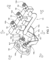


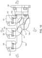


Classifications
-
- H—ELECTRICITY
- H05—ELECTRIC TECHNIQUES NOT OTHERWISE PROVIDED FOR
- H05K—PRINTED CIRCUITS; CASINGS OR CONSTRUCTIONAL DETAILS OF ELECTRIC APPARATUS; MANUFACTURE OF ASSEMBLAGES OF ELECTRICAL COMPONENTS
- H05K7/00—Constructional details common to different types of electric apparatus
- H05K7/14—Mounting supporting structure in casing or on frame or rack
- H05K7/1422—Printed circuit boards receptacles, e.g. stacked structures, electronic circuit modules or box like frames
- H05K7/1427—Housings
- H05K7/1432—Housings specially adapted for power drive units or power converters
- H05K7/14329—Housings specially adapted for power drive units or power converters specially adapted for the configuration of power bus bars
-
- H—ELECTRICITY
- H02—GENERATION; CONVERSION OR DISTRIBUTION OF ELECTRIC POWER
- H02M—APPARATUS FOR CONVERSION BETWEEN AC AND AC, BETWEEN AC AND DC, OR BETWEEN DC AND DC, AND FOR USE WITH MAINS OR SIMILAR POWER SUPPLY SYSTEMS; CONVERSION OF DC OR AC INPUT POWER INTO SURGE OUTPUT POWER; CONTROL OR REGULATION THEREOF
- H02M7/00—Conversion of AC power input into DC power output; Conversion of DC power input into AC power output
- H02M7/66—Conversion of AC power input into DC power output; Conversion of DC power input into AC power output with possibility of reversal
- H02M7/68—Conversion of AC power input into DC power output; Conversion of DC power input into AC power output with possibility of reversal by static converters
- H02M7/72—Conversion of AC power input into DC power output; Conversion of DC power input into AC power output with possibility of reversal by static converters using discharge tubes with control electrode or semiconductor devices with control electrode
- H02M7/79—Conversion of AC power input into DC power output; Conversion of DC power input into AC power output with possibility of reversal by static converters using discharge tubes with control electrode or semiconductor devices with control electrode using devices of a triode or transistor type requiring continuous application of a control signal
- H02M7/797—Conversion of AC power input into DC power output; Conversion of DC power input into AC power output with possibility of reversal by static converters using discharge tubes with control electrode or semiconductor devices with control electrode using devices of a triode or transistor type requiring continuous application of a control signal using semiconductor devices only
-
- B—PERFORMING OPERATIONS; TRANSPORTING
- B60—VEHICLES IN GENERAL
- B60L—PROPULSION OF ELECTRICALLY-PROPELLED VEHICLES; SUPPLYING ELECTRIC POWER FOR AUXILIARY EQUIPMENT OF ELECTRICALLY-PROPELLED VEHICLES; ELECTRODYNAMIC BRAKE SYSTEMS FOR VEHICLES IN GENERAL; MAGNETIC SUSPENSION OR LEVITATION FOR VEHICLES; MONITORING OPERATING VARIABLES OF ELECTRICALLY-PROPELLED VEHICLES; ELECTRIC SAFETY DEVICES FOR ELECTRICALLY-PROPELLED VEHICLES
- B60L15/00—Methods, circuits, or devices for controlling the traction-motor speed of electrically-propelled vehicles
- B60L15/007—Physical arrangements or structures of drive train converters specially adapted for the propulsion motors of electric vehicles
-
- H—ELECTRICITY
- H01—ELECTRIC ELEMENTS
- H01R—ELECTRICALLY-CONDUCTIVE CONNECTIONS; STRUCTURAL ASSOCIATIONS OF A PLURALITY OF MUTUALLY-INSULATED ELECTRICAL CONNECTING ELEMENTS; COUPLING DEVICES; CURRENT COLLECTORS
- H01R31/00—Coupling parts supported only by co-operation with counterpart
- H01R31/06—Intermediate parts for linking two coupling parts, e.g. adapter
-
- H—ELECTRICITY
- H02—GENERATION; CONVERSION OR DISTRIBUTION OF ELECTRIC POWER
- H02K—DYNAMO-ELECTRIC MACHINES
- H02K11/00—Structural association of dynamo-electric machines with electric components or with devices for shielding, monitoring or protection
- H02K11/30—Structural association with control circuits or drive circuits
- H02K11/33—Drive circuits, e.g. power electronics
-
- H—ELECTRICITY
- H02—GENERATION; CONVERSION OR DISTRIBUTION OF ELECTRIC POWER
- H02K—DYNAMO-ELECTRIC MACHINES
- H02K5/00—Casings; Enclosures; Supports
- H02K5/04—Casings or enclosures characterised by the shape, form or construction thereof
-
- H—ELECTRICITY
- H02—GENERATION; CONVERSION OR DISTRIBUTION OF ELECTRIC POWER
- H02M—APPARATUS FOR CONVERSION BETWEEN AC AND AC, BETWEEN AC AND DC, OR BETWEEN DC AND DC, AND FOR USE WITH MAINS OR SIMILAR POWER SUPPLY SYSTEMS; CONVERSION OF DC OR AC INPUT POWER INTO SURGE OUTPUT POWER; CONTROL OR REGULATION THEREOF
- H02M7/00—Conversion of AC power input into DC power output; Conversion of DC power input into AC power output
- H02M7/003—Constructional details, e.g. physical layout, assembly, wiring or busbar connections
Definitions
- JP5455887B2 discloses a power converter having the connector for electric connection with the motor.
- This connector is fixed to one of side walls of a case, and has three plugs provided so as to project outside the case.
- the center of the plug is disposed annularly.
- busbars (a U-phase busbar, a V-phase busbar, and a W-phase busbar) which electrically connect the connector to a power module are routed so that each busbar extends toward the connector from the inside of the case.
- the three busbars are routed so that they are parallel to each other in the depth direction of the case at the same height, and they are separated in the width direction of the one side wall.
- the present invention is made in view of the problem described above, and one purpose thereof is to provide a power converter capable of reducing an appearance size, while securing workability in association with connection between a connector and busbars.
- a power converter according to the present invention is defined in claim 1.
- One aspect includes a power module part and a connector part.
- the power module part has n power modules, n being an integer of 2 or more.
- the connector part has n busbars connected to the n power modules, respectively, and a connector connected to the n busbars and to be connected with an external apparatus.
- the busbar connected to the first power module is a first busbar
- the connecting part of the first busbar is a first connecting part
- the coupling part of the first busbar is a first coupling part
- the busbar connected to the second power module is a second busbar
- the connecting part of the second busbar is a second connecting part
- the coupling part of the second busbar is a second coupling part
- one of the n connection points to which the first connecting part is connected is a first connection point
- another of the n connection points to which the second connecting part is connected is a second connection point.
- the first connection point and the second connection point are offset in a second direction intersecting with the first direction, and the first connection point is disposed closer to the power module part than the second connection point in the second direction.
- the second coupling part has a length longer than the first coupling part, and the second coupling part is routed so as to bypass outside of an area of the connector where the n connection points are disposed, when seen in the first direction.
- the appearance size can be reduced, while securing the workability in association with the connection of the busbars to the connector.
- the connector part may be an AC connector part configured to perform input and output of three-phase AC power to and from the external apparatus (here, the n may be 3).
- the power module part may include a third power module further lined up with the first power module and the second power module in the first direction.
- the busbar connected to the third power module is a third busbar
- the connecting part of the third busbar is a third connecting part
- the coupling part of the third busbar is a third coupling part
- one of the n connection points to which the third connecting part is connected is a third connection point.
- the first connection point, the second connection point, and the third connection point may be disposed annularly, when seen in a plan view in the first direction.
- the third coupling part may have a length longer than the first coupling part, and the third coupling part may be routed so as to bypass outside of the area of the connector where the n connection points are disposed, when seen in the plan view in the first direction.
- the AC connector part has the three busbars, and the busbars are routed so that the coupling part of the third busbar also bypasses outside the connection area, the high workability in association with the connection of the busbars to the connector can be secured, even if gaps between the coupling part of the third busbar and the coupling parts of other busbars (the first and second busbars) are narrowed.
- the first coupling part, the second coupling part, and the third coupling part may be routed so that the first coupling part and the third coupling part oppose each other at a first spot, while the second coupling part does not oppose the first coupling part and the third coupling part at the first spot, and the second coupling part and the third coupling part oppose each other at a second spot, while the first coupling part does not oppose the second coupling part and the third coupling part at the second spot.
- the second coupling part in the part where the first coupling part and the third coupling part oppose each other (the first spot), the second coupling part is separated therefrom, and in the part where the second coupling part and the third coupling part oppose each other (the second spot), the first coupling part is separated therefrom. Therefore, the size of the area where the busbars are routed can be reduced as compared with a case where the coupling parts of all the three busbars oppose each other.
- the second coupling part and the third coupling part are routed so as to bypass on the opposite side from the side of the opening of the case (the one side) with respect to the connection area, the operator can access the connection area from the opening of the case body when connecting the busbars to the connector. Therefore, the high workability for connecting the busbars to the connector can be secured, while enabling the reduction in the appearance size of the device.
- the case body since the case body opens upwardly, the operator can access the connection area easily from above of the vehicle when connecting the busbars to the connector. Therefore, it is advantageous for securing the high workability.
- the second connection point may be disposed on an input side of an impact load expected in the vehicle, from the first connection point and the third connection point.
- the second coupling part may have a part adjacent to the second connecting part, the part extending in the up-and-down direction of the vehicle and being separated from the first coupling part and the third coupling part.
- the part of the case accommodating the connector part (hereinafter, referred to as the "connector accommodating part") is disposed so that it is located on the input side of the impact load, and the end of the case on the connector accommodating part side is disposed so that it becomes flush with the motor housing or the axle housing, or is located on the opposite side from the end, compared to the motor housing or the axle housing.
- the impact load will not be intensively inputted into the end of the case of the power converter even if the impact load is applied, thereby securing the high safety.
- the n busbars may be molded by insulating material so that the coupling parts become integral.
- the coupling parts of all the busbars are molded integrally by the insulating material, the n busbars can be handled as one component. Therefore, the high workability can be secured when assembling the power converter, as compared with a case where the n busbars are handled independently.
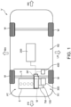
- a configuration of a vehicle V to which a power converter 100 according to a first embodiment of the present invention is mounted is described with reference to Fig. 1 .
- a front-and-rear direction of the vehicle V is simply described as the "front-and-rear direction”
- a left-and-right direction of the vehicle V (vehicle width direction)
- an up-and-down direction of the vehicle V is simply described as the "up-and-down direction.”
- the vehicle V carries a powertrain PT, the power converter 100, a high-voltage battery 200, and a low-voltage battery 300.
- the vehicle V may be a so-called “Hybrid Electric Vehicle (HEV),” which carries an engine E and a motor M which function as a drive source for propelling (i.e., a drive source of the vehicle V (wheels W)).
- HEV Hybrid Electric Vehicle
- the powertrain PT may include the engine E and the motor M.
- the powertrain PT may also include a transmission TM and a differential gear DF.
- the motor M may be a alternating current (AC) motor, particularly a three-phase three-wire alternating current (AC) motor which rotates in response to supply of three-phase AC power, and includes an output shaft, a rotor particularly having permanent magnets arranged around the output shaft, and a stator which is disposed radially outward of the rotor and where coils are wound around a plurality of teeth.
- the plurality of coils may be comprised of a U-phase coil, and a V-phase coil, and a W-phase coil, and currents of different phases may be supplied to the coils.
- the transmission TM may be connected with the motor M, and reduce the speed of rotation (changes the gear stage) inputted from the motor M and output the reduced rotation.
- the differential gear DF may transmit the rotation outputted from the transmission TM to the wheels W via a drive shaft S.
- the vehicle V may be a parallel-type hybrid electric vehicle as one example, which is propelled by the motor M, by the engine E, or by both the motor M and the engine E. Note that the vehicle V is capable of performing regenerative deceleration so that the motor M generates electric power by a transferring force from the wheels W when the vehicle V decelerates.
- the high-voltage battery 200 may be a battery which supplies and receives electric power to/from the motor M.
- the high-voltage battery 200 supplies electric power to the motor M.
- the motor M is used as a generator when the vehicle V decelerates, the high-voltage battery 200 stores electric power generated by the motor M.
- the power converter 100 may be an inverter device connected to the three-phase three-wire system motor M, and converts direct current (DC) power from the high-voltage battery 200 into AC power, and then supplies it to the motor M. In detail, the power converter 100 converts DC power into three-phase AC power.
- DC direct current
- the power converter 100 converts the AC power generated by the motor M into DC power, and then supplies it to the high-voltage battery 200.
- the low-voltage battery 300 may be a battery for supplying electric power to electrical components provided to each part of the vehicle V
- the low-voltage battery 300 may be a battery which is lower in the nominal voltage than the high-voltage battery 200.
- the high-voltage battery 200 may be a lithium-ion battery or a nickel-hydrogen battery of which the nominal voltage may be 24V (or about 24V) or higher
- the low-voltage battery 300 may be a lead battery or a lithium-ion battery of which the nominal voltage may be 12V (or about 12V) or 24V (or about 24V).
- the powertrain PT, the power converter 100, and the low-voltage battery 300 may be accommodated in a powertrain room (or compartment) R1 formed in a front part of the vehicle V
- the high-voltage battery 200 may be mounted under a floor of a cabin R2 formed behind the powertrain room R1.
- PCM Powertrain Control Module 400 which is a controller for totally controlling the powertrain PT including the motor M and the engine E may also be mounted on the vehicle V
- Fig. 2 is a front view of the power converter 100 and its peripheral (or auxiliary) equipment, when seen from the front side of the vehicle V
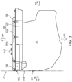
- Fig. 3 is a side view of the power converter 100 and the motor M, when seen from the left side of the vehicle V Note that Figs. 2 and 3 omit illustration of the low-voltage battery 300.
- the engine E in the powertrain room R1, the engine E, the motor M, and the transmission TM may be disposed in this order from the right side.
- the engine E includes an engine lower part 501 and an engine upper part 502 disposed above the engine lower part 501.
- the motor M is disposed adjacent to the engine lower part 501 of the engine E on the left side.
- the motor M may include a first motor housing 511 and a second motor housing 521 as outer cells.
- the first motor housing 511 is joined to a left-side external surface of the engine lower part 501, and the second motor housing 521 is connected to the left side of the first motor housing 511 without a gap.
- the transmission TM may have an axle housing 531 as an outer cell.
- the axle housing 531 has a frustum shape of which the cross-sectional size is reduced gradually from the right side toward the left side.
- the power converter 100 may be disposed above the second motor housing 521 and the axle housing 531, in the left-and-right direction of the vehicle V
- the power converter 100 has a connector part, particularly an AC connector part 150 in a front part of the vehicle V
- the AC connector part 150 has busbars and a connector therein for connection with the motor M, and a lower surface of a case (housing) is located below other parts of the power converter 100.
- a case 101 may be constituted by a combination of a case body (housing body) 102 having an upward opening, and a lid 103 which closes the opening of the case body 102.
- an end part (front end part) 150a of the case 101 of the power converter 100, where the AC connector part 150 is accommodated is disposed at a position which is substantially along the imaginary line L1. That is, in this embodiment, the power converter 100 may be disposed so that the front end part 150a of the AC connector part 150 becomes flush with the front end part 511a of the first motor housing 511.
- the power converter 100 may have a PCM connector 143 which projects upwardly from an upper surface 101a of the case 101.
- the PCM 400 (see Fig. 1 ) is connected to the power converter 100 via the PCM connector 143.
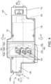
- Fig. 4 is a plan view of the power converter 100, seen from above.
- the power converter 100 may include a DC connector part 110, a noise removing part 120, a smoothing part 130, and a power module part 140, as well as the AC connector part 150, which may be accommodated inside the case 101.
- the DC connector part 110, the noise removing part 120, the smoothing part 130, the power module part 140, and the AC connector part 150 may be disposed in this order from the rear side of the vehicle V.
- the AC connector part 150 may be disposed so that a center line L3 in the left-and-right direction is offset to the right (arrow A) from a center line L2 of other parts of the power converter 100.
- the DC connector part 110 has a plurality of terminals used for connection with the high-voltage battery 200.
- the noise removing part 120 is a functional part for preventing leaking of noise of a high frequency component from the power converter 100, and, for example, it includes a ferrite core.
- the noise removing part 120 may be inserted in an electric power passage between the DC connector part 110 and the smoothing part 130.
- the smoothing part 130 is a functional part which smooths DC power, and it includes a smoothing capacitor (e.g., a film capacitor).
- the smoothing part 130 may be inserted in an electric power passage between the noise removing part 120 and the power module part 140.
- the power module part 140 may include a module body 141 having three IGBTs (Insulated Gate Bipolar Transistors) 144a-144c which are each examples of a power module, and a controller circuit 142 which electrically controls the IGBTs 144a-144c of the module body 141. Note that the three IGBTs 144a-144c of the module body 141 are lined up in the left-and-right direction (i.e., a first direction).
- IGBTs Insulated Gate Bipolar Transistors
- the PCM connector 143 may be connected to the controller circuit 142.
- a controller formed in the controller circuit 142 controls the IGBTs 144a-144c of the module body 141 in response to a command from the PCM 400, and changes a conversion amount of DC power and AC power. Note that, below, the IGBTs 144a-144c may collectively be referred to as the "IGBT 144.”
- the module body 141 of the power module part 140 may be constituted by a combination of electronic components, such as power semiconductors, including the IGBT 144, corresponding to the U-phase, the V-phase, and the W-phase.
- the module body part 141 of the power module part 140 may be inserted in an electric power passage between the smoothing part 130 and the AC connector part 150.
- the AC connector part 150 has a connector and busbars used for electrically connecting with the motor M.
- the power converter 100 sends out AC power toward the motor M via the AC connector part 150. Further, when the motor M functions as the generator when the vehicle V decelerates, the power converter 100 accepts AC power from the motor M via the AC connector part 150.
- DC power outputted from the high-voltage battery 200 may be inputted into the noise removing part 120 via the DC connector part 110.
- the DC power which passed the noise removing part 120 is smoothed by the smoothing part 130, and is sent out to the power module part 140.
- the power module part 140 converts the DC power into AC power, particularly three-phase AC power, according to a command from the PCM 400. Then, the converted three-phase AC power is sent out to the motor M via the AC connector part 150.
- the three-phase AC power generated by the motor M may be inputted into the power module part 140 via the AC connector part 150. Then, the inputted AC power is converted into DC power by the power module part 140. The converted DC power is sent out to the high-voltage battery 200 via the DC connector part 110 after smoothing by the smoothing part 130 and removal of the noise of a high frequency component by the noise removing part 120. Therefore, the high-voltage battery 200 is charged.
- a DC-DC converter (not illustrated) may be inserted in an electric power passage between the power converter 100 and the high-voltage battery 200.
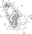
- FIG. 5 is a perspective view illustrating the power converter 100 where the lid 103 is removed from the case body 102.
- Fig. 6 is a perspective view illustrating a partial configuration of a motor-side connector 512 and the AC connector part 150.
- Fig. 7 is a perspective view illustrating a partial configuration of the AC connector part 150 where a resin mold part 155 is omitted.
- the electric connection between the motor M and the power converter 100 may be made by fitting of the motor-side connector 512 into a connector 156 of the AC connector part 150 (arrow B).
- the motor-side connector 512 maybe fixed to the first motor housing 511, and a part thereof may be inserted into the case body 102 of the case 101.
- the motor-side connector 512 may have a pillar-shaped base part 512a and three terminals 512b-512d projected to the left from an end surface of the base part 512a.
- terminals 512b-512d are electrically connected to U-phase, V-phase, and W-phase motor coils of the motor M via wiring (not illustrated).
- the motor-side connector 512 may be disposed so that a part of the base part 512a and the three terminals 512b-512d are inserted in the case body 102. Inside the case body 102, the terminals 512b-512d of the motor-side connector 512 are inserted into female terminals (not illustrated) of the connector 156 of the AC connector part 150 (arrows C in Fig. 6 ) so that the motor-side connector 512 and the connector 156 are electrically connected to each other.
- the terminal 512b may be a U-phase terminal
- the terminal 512c may be a V-phase terminal
- the terminal 512d may be a W-phase terminal.
- the connector 156 has one or more connection points, particularly three connection points 156a-156c on the opposite side (left side) of the part for accepting the insertion of the terminals 512b-512d of the motor-side connector 512.
- Each of the connection points 156a-156c may have a cylindrical shape.
- the three connection points 156a-156c may be disposed annularly in a plan view in the left-and-right direction. That is, the three connection points 156a-156c are disposed in a plane defined by the front-and-rear direction and the vertical direction, which intersects with the first direction (left-and-right direction). The plane and the first direction intersect as opposed to the first direction lying in the plane.
- an AC busbar module 151 is connected to the connector 156 e.g. by being fastened with bolts BLT.
- the AC busbar module 151 has one or more busbars, particularly three busbars 152-154, and optionally the resin mold part 155.
- the first busbar 152 includes a first connecting part 152a connected with a first connection point 156a of the connector 156, a module-side connecting part 152b connected with the IGBT 144a of the power module part 140, and a first coupling part 152c which continuously couples the connecting part 152a to the module-side connecting part 152b.
- the second busbar 153 includes a second connecting part 153a connected with the second connection point 156b of the connector 156, a module-side connecting part 153b connected with the IGBT 144b of the power module part 140, and a second coupling part 153c which continuously couples the connecting part 153a to the module-side connecting part 153b.
- the third busbar 154 includes a third connecting part 154a connected with the third connection point 156c of the connector 156, a module-side connecting part 154b connected with the IGBT 144c of the power module part 140, and a third coupling part 154c which continuously couples the connecting part 154a to the module-side connecting part 154b.
- the resin mold part 155 may be made of insulating material (e.g., epoxy resin), and it may be formed so that it covers outer circumferential parts of the busbars 152-154 and is filled in the gaps between the busbars 152-154. Therefore, the AC busbar module 151 may be handled as one component when assembling the power converter 100.
- insulating material e.g., epoxy resin
- the busbar 152 may be a U-phase busbar
- the busbar 153 may be a V-phase busbar
- the busbar 154 may be a W-phase busbar.
- FIG. 8 is a plan view illustrating the busbars 152-154, when seen from above.
- Fig. 9 is a side view illustrating the busbars 152-154 and the connector 156, when seen from the left.
- Fig. 10 is a rear view illustrating the busbars 152-154, when seen from the rear.
- connection point 156a is offset from the connection points 156b and 156c in the front-and-rear direction (i.e., a second direction intersecting with the first direction). Since the power module part 140 is located rearward of the connector 156 (see Fig. 5 ), the first connection point 156a is disposed closer to the power module part 140 and the second connection point 156b is disposed farther from the power module part 140, in the second direction. In detail, the connection point 156a is disposed rearward of the connection points 156b and 156c (toward the power module part 140).
- connection point 156c is disposed rearward of the connection point 156b.
- the connecting part 152a of the busbar 152 is offset rearwardly of the connecting parts 153a and 154a of the busbars 153 and 154, respectively.
- the connection points 156a-156c of the connector 156 may be disposed annularly in a plan view in the left-and-right direction.
- the coupling part 152c may be the shortest of the three and the coupling part 154c is the longest.
- the coupling part 153c has a length longer than the coupling part 152c, where the length may be measured along the center of a three-dimensional route over which the coupling part 153c extends from the connecting part 153a to the module-side connecting part 153b.
- the coupling part 154c also has a length longer than the coupling part 152c.
- the coupling parts 152c, 153c, and 154c of the busbars 152-154 may have parts which extend linearly in the front-and-rear direction and are parallel to each other adjacent to the module-side connecting parts 152b, 153b, and 154b, respectively.
- current sensors 157-159 may be attached to the parts of the busbars 152-154 which extend linearly, respectively.
- the current sensors 157-159 are sensors which detect values of current flowing through the busbars 152-154, although the detailed explanation is omitted because they are known sensors.
- the coupling parts 152c, 153c, and 154c of the busbars 152-154 may be bent downwardly at front ends of the parts which extend linearly in the front-and-rear direction.
- the coupling part 152c of the busbar 152 may extend rightwardly from the downwardly-extending part, may further extend forwardly, and is coupled to the connecting part 152a.
- the coupling part 153c of the busbar 153 may extend rightwardly from the downwardly-extending part, may further extend downwardly, forwardly, upwardly, and then rightwardly, and is coupled to the connecting part 153a.
- the coupling part 153c may be coupled to the connecting part 153a from the front.
- the busbar 153 is routed so that the coupling part 153c of the busbar 153 does not cross an area (E1 area in Fig. 9 ) where the three connection points 156a-156c (see Fig. 7 ) of the connector 156 are disposed.
- the coupling part 153c of the busbar 153 does not cross in the front-and-rear direction the area (E1 area) where the three connection points 156a-156c of the connector 156 are disposed, but it is routed to bypass below the area, around the outer circumference of this area.
- the coupling part 153c of the busbar 153 is routed so that the vicinity of the coupling part to the connecting part 153a extends in the up-and-down direction, this part is disposed so that the coupling parts 152c and 154c of the busbars 152 and 154 do not come close to this part.
- the coupling part 154c of the busbar 154 may extend rightwardly from the downwardly-extending part, may further extend downwardly and then rightwardly, and is coupled to the connecting part 154a. As illustrated in Fig. 9 , in the busbar 154, the coupling part 154c may be coupled to the connecting part 154a from below.
- the busbar 154 is routed so that the coupling part 154c of the busbar 154 does not cross the above-described area of the connector 156. That is, the coupling part 154c of the busbar 154 does not cross the area (E1 area), but it is routed so as to bypass below the outer circumference of this area.
- the coupling part 152c of the busbar 152 and the coupling part 154c of the busbar 154 oppose each other at D2 part in Fig. 8 and F2 part in Fig. 10 , they are routed so that these opposing parts are separated from the coupling part 153c of the busbar 153.
- the coupling part 153c of the busbar 153 and the coupling part 154c of the busbar 154 oppose each other at D1 and D3 parts in Fig. 8 , E2 part in Fig. 9 , and F1 part in Fig. 10 , they are routed so that these opposing parts are separated from the coupling part 152c of the busbar 152.
- the appearance size can be reduced, while securing the workability in association with the connection of the busbars 152-154 to the connector 156.
- the AC connector part 150 since the AC connector part 150 has the three busbars 152-154, and the busbars 152-154 are routed so that the coupling part 154c of the busbar 154 also bypasses the outer circumference of this area E1, the high workability in association with the connection of the busbars 152-154 to the connector 156 can be secured, even if the gaps between the busbars 154 and the coupling parts 152c and 153c of other busbars 152 and 153 are narrowed.
- the coupling part 153c of the busbar 153 and the coupling part 154c of the busbar 154 are routed so as to bypass below the E1 area (on the opposite side of the opening of the case body 102), the operator can access the E1 area easily from the opening of the case body 102 when connecting the busbars 152-154 to the connector 156. Therefore, the high workability for connecting the busbars 152-154 to the connector 156 can be secured, while enabling the reduction in the appearance size of the device 100.
- the case body 102 since the case body 102 opens upwardly, the operator can access the E1 area easily from above of the vehicle V when connecting the busbars 152-154 to the connector 156. Therefore, it is advantageous for securing the high workability.
- the coupling part 153c of the busbar 153 since the coupling part 153c of the busbar 153 has the vertically extending part provided so that it extends in the up-and-down direction at the part separated from the coupling part 152c of the busbar 152 and the coupling part 154c of the busbar 154, the vertically extending part of the coupling part 153c of the busbar 153 deforms independently, if an impact load is inputted into the vehicle V from the front. For this reason, in the power converter 100, a part of the impact load can be absorbed by the deformation of the coupling part 153c of the busbar 153, thereby suppressing short circuits of the other busbars 152 and 154 and action of the impact load on the power module part 140. Therefore, the power converter 100 is advantageous by securing the high safety of the vehicle V carrying the power converter 100.
- the connector accommodating part which accommodates the AC connector part 150 of the case 101 is disposed so that it is located on the input side of the impact load (front side), and the end part 150a of the case 101 on the connector accommodating part side is disposed so that it becomes flush with the first motor housing 511, the impact load will not be intensively inputted into the end part 150a of the case 101 of the power converter 100 even if the impact load is inputted from the front, thereby securing the high safety.
- the coupling parts 152c, 153c, and 154c of all the busbars 152-154 are molded integrally by the resin mold part 155, the three busbars 152-154 can be handled as one component. Therefore, the high workability can be secured when assembling the power converter 100, as compared with the case where the three busbars 152-154 are handled independently.
- the appearance size can be reduced, while securing the workability in association with the connection of the busbars 152-154 to the connector 156.
- a power converter 160 according to a second embodiment of the present invention is described with reference to Figs. 11 and 12 .
- the power converter 160 according to this embodiment has the same configuration as the first embodiment, except that it is connected to a three-phase four-wire motor M.
- Figs. 11 and 12 a partial configuration of an AC connector part 250 is selectively illustrated. Further, below, explanation of the part overlapping with the first embodiment is omitted.
- the power converter 160 may be an inverter device connected to the three-phase four-wire AC motor M.
- the AC connector part 250 of the power converter 160 has a connector 256 and an AC busbar module 251 which are used for the electric connection with the motor M.
- the power converter 160 also sends out AC power toward the motor M via the AC connector part 250. Further, when the motor M functions as a power generator as the vehicle V decelerates, the power converter 160 accepts the AC power from the motor M via the AC connector part 250.
- the connector 256 has four connection points (H area). Each connection point has a cylindrical shape, similarly to the connection points 156a-156c of the first embodiment.
- the AC busbar module 251 is connected to the connector 256 e.g. by being fastened with bolts BLT. As illustrated in Figs. 11 and 12 , the AC busbar module 251 has four busbars 252-255 and optionally a resin mold part. Note that, in Figs. 11 and 12 , illustration of the resin mold part is omitted.
- the busbar 252 may be a U-phase busbar
- the busbar 253 may be a V-phase busbar
- the busbar 254 may be a W-phase busbar
- the busbar 255 may be a neutral (N-phase) busbar.
- the busbar (first busbar) 254 has a connecting part (first connecting part) 254a connected with a W-phase connection point (first connection point) of the connector 256, a module-side connecting part 254b connected with a W-phase IGBT of the power module part, and a coupling part (first coupling part) 254c which continuously couples the connecting part 254a to the module-side connecting part 254b.
- the busbar (second busbar) 253 has a connecting part (second connecting part) 253a connected with a V-phase connection point (second connection point) of the connector 256, a module-side connecting part 253b connected with a V-phase IGBT of the power module part, and a coupling part (second coupling part) 253c which continuously couples the connecting part 253a to the module-side connecting part 253b.
- the busbar (third busbar) 252 has a connecting part (third connecting part) 252a connected with a U-phase connection point (third connection point) of the connector 256, a module-side connecting part 252b connected with a U-phase IGBT of the power module part, and a coupling part (third coupling part) 252c which continuously couples the connecting part 252a to the module-side connecting part 252b.
- the busbar 255 has a connecting part 255a connected with a neutral-line connection point connected at the neutral point of the motor M of the connector 256, a module-side connecting part 255b connected to a neutral-line IGBT of the power module part, or the neutral line itself, and a coupling part 255c which continuously couples the connecting part 255a to the module-side connecting part 255b.
- the resin mold part may be made of insulating material (e.g., epoxy resin), covers outer circumferential parts of the busbars 252-255, and may be inserted in gaps between the busbars 252-255, as in the first embodiment. Therefore, the AC busbar module 251 is handled as one component when assembling the power converter 160.
- insulating material e.g., epoxy resin
- the connecting part 254a of the busbar 254 is offset rearwardly from the connecting parts 253a and 255a of the busbars 253 and 255.
- the connecting part 252a of the busbar 252 is also offset rearwardly from the connecting parts 253a and 255a of the busbars 253 and 255, and is disposed at substantially the same position as the connecting part 254a of the busbars 254 in the front-and-rear direction.
- the coupling parts 252c, 253c, 254c, and 255c of the busbars 252-255 may have parts which extend linearly in the front-and-rear direction, and are parallel to each other adjacent to the module-side connecting parts 252b, 253b, 254b, and 255b, respectively.
- a current sensor may be attached to the linearly-extending part of each of the busbars 252-255.
- the coupling parts 252c, 253c, 254c, and 255c of the busbars 252-255 may be bent downwardly at the front ends of the linearly-extending parts in the front-and-rear direction.
- the coupling part 254c of the busbar 254 may extend rightwardly from the downwardly-extending part, may further extend forwardly, and is coupled to the connecting part 254a.
- the coupling part 253c of the busbar 253 may extend rightwardly from the downwardly-extending part, may further extend downwardly, forwardly, and upwardly, and is coupled to the connecting part 253a.
- the coupling part 253c is coupled to the connecting part 253a from below.
- the coupling part 253c of the busbar 253 is routed so that it does not cross the H area where the four connection points of the connector 256 are disposed. That is, the coupling part 253c of the busbar 253 does not cross the H area in the front-and-rear direction where the four connection points of the connector 256 are disposed, but it is routed so that it bypasses below the outer circumference of this area.
- the coupling part 252c of the busbar 252 may extend rightwardly from the downwardly-extending part, may further extend downwardly, rightwardly, and forwardly, and is coupled to the connecting part 252a. As illustrated in Fig. 12 , in the busbar 252, the coupling part 252c is coupled to the connecting part 252a from the rear. Further, the coupling part 252c of the busbar 252 is routed so that it does not cross the H area of the connector 256. That is, the coupling part 252c of the busbar 252 does not cross the H area, either, but it is routed so that it bypasses the rear of the outer circumference of this area.
- the coupling part 255c of the busbar 255 may extend rightwardly from the downwardly-extending part, may further extend downwardly, forwardly, upwardly, and rearwardly, and is coupled to the connecting part 255a. As illustrated in Fig. 12 , in the busbar 255, the coupling part 255c is coupled to the connecting part 255a from the front. Further, the coupling part 255c of the busbar 255 is routed so that it does not cross the H area of the connector 256. That is, the coupling part 255c of the busbar 255 does not cross the H area either, but is instead routed so that it bypasses the rear of the outer circumference of this area.
- the coupling parts 252c, 253c, 254c, and 255c of the four busbars 252-255 may be routed so that only two of the busbars overlap with each other in the part where the busbars overlap with each other (the part where the principal surfaces oppose each other).
- the coupling part 254c of the busbar 254 and the coupling part 253c of the busbar 253 oppose each other at G4 part in Fig. 11
- the coupling parts 252c and 255c of other busbars 252 and 255 are routed so that they are separated therefrom at this part.
- the coupling part 253c of the busbar 253 and the coupling part 252c of the busbar 252 oppose each other at G2 part in Fig. 11 , the coupling parts 254c and 255c of other busbars 254 and 255 are routed so that they are separated therefrom at this part.
- the coupling part 252c of the busbar 252 and the coupling part 255c of the busbar 255 oppose each other at G1 part in Fig. 11
- the coupling parts 253c and 254c of other busbars 253 and 254 are routed so that they are separated therefrom at this part.
- the coupling parts 252c and 254c of the busbars 252 and 254 are routed so that they are separated therefrom at this part.
- the coupling parts 252c, 253c, 254c, and 255c of the busbars 252-255 are routed so that only two of the coupling parts are overlapped with each other at most as described above, the thickness of the overlapping part (the part where the principal surfaces oppose each other) can be reduced, as compared with the case where three or all the coupling parts 252c, 253c, 254c, and 255c of the four busbars 252-255 overlap with each other.
- the power converter 160 according to this embodiment also has the same configuration as the first embodiment, except for the AC connector part 250 having the four busbars 252-255. Therefore, the power converter 160 according to this embodiment can also achieve the same effects as the first embodiment.
- the neutral line of the three-phase four-wire type may be grounded by electrically connecting it to a vehicle body part which is possible to be grounded, or the negative electrode of the battery.
- the busbar 255 connected to the neutral line is located forward of the busbars 252-254, the risk of short circuit with a case (not illustrated) of the power converter 160 can further be reduced as compared with the first embodiment, when an impact load is inputted to the case from the front. Therefore, the power converter 160 is advantageous for securing the high safety of the vehicle V carrying the power converter 160.
- a power converter 170 according to a third embodiment of the present invention is described with reference to Figs. 13 and 14 .
- the power converter 170 according to this embodiment has the same configuration as the first embodiment, except for the power converter 170 being connected to a single-phase two-wire motor M.
- a partial configuration of an AC connector part 350 is selectively illustrated. Note that, below, explanation of the part overlapping with the first embodiment is omitted.
- the power converter 170 may be an inverter device connected to the single-phase two-wire AC motor M.
- the AC connector part 350 of the power converter 170 has a connector 356 and an AC busbar module 351 which are used for the electric connection with the motor M.
- the power converter 170 also sends out AC power toward the motor M via the AC connector part 350. Further, when the motor M functions as a power generator as the vehicle V decelerates, the power converter 170 accepts the AC power from the motor M via the AC connector part 350.
- the connector 356 has two connection points (J area). Each connection point may have a cylindrical shape, similarly to the connection points 156a-156c of the first embodiment.
- the AC busbar module 351 is connected to the connector 356 e.g. by being fastened with bolts BLT. As illustrated in Figs. 13 and 14 , the AC busbar module 351 has two busbars 352 and 353 and optionally a resin mold part. In Figs. 13 and 14 , illustration of the resin mold part is omitted.
- the busbar 352 may be a U-phase busbar, and the busbar 353 may be an N-phase busbar.
- the busbar (first busbar) 352 has a connecting part (first connecting part) 352a connected with a U-phase connection point (first connection point) of the connector 356, a module-side connecting part 352b connected with a U-phase IGBT of the power module part, and a coupling part (first coupling part) 352c which continuously couples the connecting part 352a to the module-side connecting part 352b.
- the busbar (second busbar) 353 has a connecting part (second connecting part) 353a connected with an N-phase connection point (second connection point) of the connector 356, a module-side connecting part 353b connected with an N-phase IGBT of the power module part, and a coupling part (second coupling part) 353c which continuously couples and the connecting part 353a to the module-side connecting part 353b.
- the resin mold part may be made of insulating material (e.g., epoxy resin), covers outer circumferential parts of the busbars 352 and 353, and is inserted into gaps between the busbars 352 and 353, as in the first embodiment. Therefore, the AC busbar module 351 is handled as one component when assembling the power converter 170.
- insulating material e.g., epoxy resin
- the connecting part 353a of the busbar 353 is offset forward from the connecting part 352a of the busbar 352.
- the coupling parts 352c and 353c of the busbars 352 and 353 may have part which extend linearly in the front-and-rear direction and are parallel to each other, adjacent to the module-side connecting parts 352b and 353b, respectively.
- a current sensor may be attached to the linearly-extending part of each of the busbars 352 and 353.
- the coupling parts 352c and 353c of the busbars 352 and 353 may be bent downwardly at front ends of the linearly-extending parts in the front-and-rear direction.
- the coupling part 352c of the busbar 352 may extend rightwardly from the downwardly-extending part, may further extend forwardly, and is coupled to the connecting part 352a.
- the coupling part 353c of the busbar 353 may extend rightwardly from the downwardly-extending part, may further extend downwardly, forwardly, upwardly, and rearwardly, and is coupled to the connecting part 353a.
- the coupling part 353c is coupled to the connecting part 353a from the front. Further, the coupling part 353c of the busbar 353 is routed so that it does not cross the J area where the two connection points of the connector 356 are disposed.
- the coupling part 353c of the busbar 353 is routed so that it does not cross in the front-and-rear direction the J area where the two connection points of the connector 356 are disposed, but it bypasses below the outer circumference of this area.
- the power converter 170 according to this embodiment also has the same configuration as the first embodiment, except for the AC connector part 350 having the two busbars 352 and 353. Therefore, the power converter 170 according to this embodiment can also achieve the same effect as the first embodiment.
- the inverter device is adopted as one example of the power converters 100, 160, and 170, the present invention is not limited to this configuration.
- the present invention may be applied to a DC-DC converter.
- the present invention may be applied to power converters used in industrial machinery.
- the vehicle not only the hybrid electric vehicle (HEV) but also a battery electric vehicle (BEV) which is not provided with an engine as a driving source for propelling the vehicle may be adopted.
- HEV hybrid electric vehicle
- BEV battery electric vehicle
- the present invention may be applied to a DC connector part.
- the resin mold part 155 is not an essential configuration in the present invention. In this case, it is desirable to keep the gap between the adjacent busbars more than the insulation distance, or to insert an insulating material at a part where the adjacent busbars are close to each other.
- connection points of the busbars to the connector may be accessible from any of the front, the rear, or below. Note that when defining the direction of access as described above, it is desirable to provide the opening in the case accordingly.
- the IGBT is adopted as one example of the power module
- the present invention is not limited to this configuration for the type of power module.
- MOSFET Metal Oxide Semiconductor Filed Effect Transistor
- a switching element and a diode element are combined.
- busbars 152-154, 252-255, and 352 and 353 are connected to the connectors 156, 256, and 356 with the bolts BLT
- the present invention is not limited to this configuration for the connection of the busbars to the connector.
- connection with nuts, connection by crimping, and connection by welding may be adopted.
- the present invention is not limited to this configuration for the orientation of the power converter. That is, it is also possible to dispose the power converter so that the end of the AC connector part faces the rear or either the left or the right.
- the power converters 100, 160, and 170 are disposed so that the front end part 150a of the AC connector parts 150, 250, and 350 becomes flush with the front end part 511a of the first motor housing 511, it is also possible to dispose the power converter in the present invention so that the front end of the AC connector part is located at a position rearward from the motor housing or the axle housing. Also in this case, it can be suppressed that the load is intensively applied to the power converter in a collision of the vehicle.
Landscapes
- Engineering & Computer Science (AREA)
- Power Engineering (AREA)
- Transportation (AREA)
- Mechanical Engineering (AREA)
- Microelectronics & Electronic Packaging (AREA)
- Electric Propulsion And Braking For Vehicles (AREA)
- Inverter Devices (AREA)
Abstract
A power converter includes a power module part having n power modules and a connector part having n busbars and a connector. First and second busbars to first and second power modules respectively have first and second connecting parts to the connector, module-side connecting parts to the power modules, and first and second coupling parts coupling the connecting part to the module-side connecting part. The connector has connection points disposed in a plane intersecting a first direction. The connection points for the first and second connecting parts are first and second connection points, respectively, and are offset so that the first connection point is closer to the power module part in a second direction intersecting the first direction. The second coupling part is longer than the first coupling part, and is routed to bypass outside an area where the connection points are disposed, when seen in the first direction.
Description
- The present invention relates to a power converter and a vehicle.
- In recent years, vehicles provided with a motor as a drive source for propelling the vehicles have increased. Such vehicles carry a high-voltage battery for supplying electric power to the motor. In addition, the vehicles also carry a power converter for converting direct current (DC) power supplied from the battery into alternating current (AC) power.
- The power converter, the motor, and the battery form an electric power supply passage therebetween by connecting connectors connected to wiring extending from the motor and the battery to a connector of the power converter.
JP5455887B2 - This connector is fixed to one of side walls of a case, and has three plugs provided so as to project outside the case. When seeing the connector from outside in the normal direction of the one side wall to which the connector is fixed, the center of the plug is disposed annularly.
- Meanwhile, three busbars (a U-phase busbar, a V-phase busbar, and a W-phase busbar) which electrically connect the connector to a power module are routed so that each busbar extends toward the connector from the inside of the case. The three busbars are routed so that they are parallel to each other in the depth direction of the case at the same height, and they are separated in the width direction of the one side wall.
- Meanwhile, for power converters adopted in various applications, a reduction in the appearance size is demanded, regardless of the power converter being a vehicle-mounted type or not. Thus, by reducing the appearance size of the power converter, the occupancy space of the overall device can be narrowed, and spaces can be used effectively.
- However, in the power converter according to the conventional technology, it is difficult to compactly dispose the three busbars connected to the connector. That is, it is necessary to secure large gaps between the busbars in consideration of the connecting work of the busbars to the connector. If narrowing the gaps between the busbars while adopting the conventional routing of the busbars, it is necessary to divide each busbar in the longitudinal direction into elements, connect an element of each busbar to the connector, and then connect each element to the remaining elements. Thus, if adopting this configuration, the connecting work becomes complicated and the number of components increases. Therefore, it is difficult to actually adopt this solution.
- Note that although the connector related to input/output of AC power to/from the power converter is described as one example, the same problem may arise also in connectors related to input/output of DC power.
- The present invention is made in view of the problem described above, and one purpose thereof is to provide a power converter capable of reducing an appearance size, while securing workability in association with connection between a connector and busbars.
- A power converter according to the present invention is defined in claim 1. One aspect includes a power module part and a connector part. The power module part has n power modules, n being an integer of 2 or more. The connector part has n busbars connected to the n power modules, respectively, and a connector connected to the n busbars and to be connected with an external apparatus.
- In the power converter according to this aspect, each of the n busbars has a connecting part connected to the connector, a module-side connecting part connected to a respective one of the n power modules, and a coupling part continuously coupling the connecting part to the module-side connecting part. The n power modules include a first power module and a second power module that are lined up in a first direction. The connector has n connection points connected with the connecting parts of the n busbars, respectively, the n connection points being disposed in a plane intersecting with the first direction.
- In the power converter according to this aspect, the busbar connected to the first power module is a first busbar, the connecting part of the first busbar is a first connecting part, the coupling part of the first busbar is a first coupling part, the busbar connected to the second power module is a second busbar, the connecting part of the second busbar is a second connecting part, the coupling part of the second busbar is a second coupling part, one of the n connection points to which the first connecting part is connected is a first connection point, and another of the n connection points to which the second connecting part is connected is a second connection point. The first connection point and the second connection point are offset in a second direction intersecting with the first direction, and the first connection point is disposed closer to the power module part than the second connection point in the second direction. The second coupling part has a length longer than the first coupling part, and the second coupling part is routed so as to bypass outside of an area of the connector where the n connection points are disposed, when seen in the first direction.
- In the power converter according to this aspect, since the second coupling part of the second busbar is routed so that it bypasses outside the area where the connection points of the connector are disposed (hereinafter, referred to as the "connection area"), the workability in association with the connection of the busbars to the connector can be secured, while reducing the device size rather than the routing of the busbars disclosed in
JP5455887B2 - In the power converter according to this aspect, the connector part may be an AC connector part configured to perform input and output of three-phase AC power to and from the external apparatus (here, the n may be 3). The power module part may include a third power module further lined up with the first power module and the second power module in the first direction.
- In the power converter according to this aspect, the busbar connected to the third power module is a third busbar, the connecting part of the third busbar is a third connecting part, the coupling part of the third busbar is a third coupling part, and one of the n connection points to which the third connecting part is connected is a third connection point. The first connection point, the second connection point, and the third connection point may be disposed annularly, when seen in a plan view in the first direction. The third coupling part may have a length longer than the first coupling part, and the third coupling part may be routed so as to bypass outside of the area of the connector where the n connection points are disposed, when seen in the plan view in the first direction.
- In the power converter according to this aspect, since the AC connector part has the three busbars, and the busbars are routed so that the coupling part of the third busbar also bypasses outside the connection area, the high workability in association with the connection of the busbars to the connector can be secured, even if gaps between the coupling part of the third busbar and the coupling parts of other busbars (the first and second busbars) are narrowed.
- In the power converter according to this aspect, the first coupling part, the second coupling part, and the third coupling part may be routed so that the first coupling part and the third coupling part oppose each other at a first spot, while the second coupling part does not oppose the first coupling part and the third coupling part at the first spot, and the second coupling part and the third coupling part oppose each other at a second spot, while the first coupling part does not oppose the second coupling part and the third coupling part at the second spot.
- In the power converter according to this aspect, in the part where the first coupling part and the third coupling part oppose each other (the first spot), the second coupling part is separated therefrom, and in the part where the second coupling part and the third coupling part oppose each other (the second spot), the first coupling part is separated therefrom. Therefore, the size of the area where the busbars are routed can be reduced as compared with a case where the coupling parts of all the three busbars oppose each other.
- The power converter according to this aspect may further include a case including a case body having an opening on one side in a third direction intersecting with both the first direction and the second direction, and accommodating the power module part and the connector part, and a lid configured to close the opening of the case body. The second coupling part and the third coupling part may be routed so as to bypass the n connection points of the connector, on the opposite side from the one side in the third direction.
- In the power converter according to this aspect, since the second coupling part and the third coupling part are routed so as to bypass on the opposite side from the side of the opening of the case (the one side) with respect to the connection area, the operator can access the connection area from the opening of the case body when connecting the busbars to the connector. Therefore, the high workability for connecting the busbars to the connector can be secured, while enabling the reduction in the appearance size of the device.
- In the power converter according to this aspect, the power converter and the external apparatus may be mounted on a vehicle. In this case, the one side in the third direction may be upward of the vehicle.
- In the power converter according to this aspect, since the case body opens upwardly, the operator can access the connection area easily from above of the vehicle when connecting the busbars to the connector. Therefore, it is advantageous for securing the high workability.
- In the power converter according to this aspect, the second connection point may be disposed on an input side of an impact load expected in the vehicle, from the first connection point and the third connection point. In this case, the second coupling part may have a part adjacent to the second connecting part, the part extending in the up-and-down direction of the vehicle and being separated from the first coupling part and the third coupling part.
- In the power converter according to this aspect, since the second coupling part of the second busbar has the part extending in the up-and-down direction (hereinafter, referred to as the "vertically extending part") at the part separated from the first coupling part and the third coupling part, the vertically extending part of the second coupling part deforms independently, if an impact load is applied to the vehicle. For this reason, in the power converter of this aspect, part of the impact load can be absorbed by the deformation of the second coupling part, thereby suppressing short circuits of other busbars and action of the impact load on the power module part. Therefore, in the power converter of this aspect, it is advantageous to secure the high safety of the vehicle carrying the power converter.
- In the power converter according to this aspect, the external apparatus may be a motor for propelling the vehicle, and have a motor housing serving as an outer cell. A transmission having an axle housing serving as an outer cell may also be mounted on the vehicle, and may be disposed adjacent to the external apparatus. The case of the power converter may be disposed on a housing of at least one of the motor housing and the axle housing so that a part of the case where the connector part is accommodated is located on the input side of the impact load, from a part of the case where the power module part is accommodated. Further, in such routing, an end of the case on the input side of the impact load may be flush with the motor housing or the axle housing, or may be located on the opposite side from the input side, compared to the motor housing or the axle housing.
- In the power converter according to this aspect, the part of the case accommodating the connector part (hereinafter, referred to as the "connector accommodating part") is disposed so that it is located on the input side of the impact load, and the end of the case on the connector accommodating part side is disposed so that it becomes flush with the motor housing or the axle housing, or is located on the opposite side from the end, compared to the motor housing or the axle housing. Thus, the impact load will not be intensively inputted into the end of the case of the power converter even if the impact load is applied, thereby securing the high safety.
- In the power converter according to this aspect, the n busbars may be molded by insulating material so that the coupling parts become integral.
- In the power converter according to this aspect, since the coupling parts of all the busbars are molded integrally by the insulating material, the n busbars can be handled as one component. Therefore, the high workability can be secured when assembling the power converter, as compared with a case where the n busbars are handled independently.
-
-
Fig. 1 is a schematic diagram illustrating a configuration of a vehicle provided with a power converter according to a first embodiment of the present invention. -
Fig. 2 is a front view illustrating a layout of the power converter. -
Fig. 3 is a side view illustrating the layout of the power converter. -
Fig. 4 is a plan view illustrating an appearance configuration of the power converter. -
Fig. 5 is a perspective view illustrating an internal configuration of the power converter. -
Fig. 6 is a perspective view illustrating a configuration of an AC busbar module and a configuration of a motor-side connector in the power converter. -
Fig. 7 is a perspective view illustrating the AC busbar module where a resin mold part is omitted. -
Fig. 8 is a plan view illustrating routing of coupling parts of busbars. -
Fig. 9 is a side view illustrating the routing of the coupling parts of the busbars. -
Fig. 10 is a rear view illustrating the routing of the coupling parts of the busbars. -
Fig. 11 is a rear view illustrating a partial configuration of an AC connector part, of a configuration of a power converter according to a second embodiment of the present invention. -
Fig. 12 is a side view illustrating a partial configuration of the AC connector part. -
Fig. 13 is a rear view illustrating a partial configuration of an AC connector part, of a configuration of a power converter according to a third embodiment of the present invention. -
Fig. 14 is a side view illustrating the partial configuration of the AC connector part. - Hereinafter, several embodiments of the present invention will be described with reference to the accompanying drawings. Note that the following embodiments illustrate the present invention exemplarily, and therefore, the present invention is not limited in any ways by the embodiments, except for its essential configuration.
- A configuration of a vehicle V to which a
power converter 100 according to a first embodiment of the present invention is mounted is described with reference toFig. 1 . Note that, below, a front-and-rear direction of the vehicle V is simply described as the "front-and-rear direction," a left-and-right direction of the vehicle V (vehicle width direction) is simply described as the "left-and-right direction," and an up-and-down direction of the vehicle V is simply described as the "up-and-down direction." - As illustrated in
Fig. 1 , the vehicle V carries a powertrain PT, thepower converter 100, a high-voltage battery 200, and a low-voltage battery 300. - The vehicle V may be a so-called "Hybrid Electric Vehicle (HEV)," which carries an engine E and a motor M which function as a drive source for propelling (i.e., a drive source of the vehicle V (wheels W)). The powertrain PT may include the engine E and the motor M. The powertrain PT may also include a transmission TM and a differential gear DF.
- The motor M may be a alternating current (AC) motor, particularly a three-phase three-wire alternating current (AC) motor which rotates in response to supply of three-phase AC power, and includes an output shaft, a rotor particularly having permanent magnets arranged around the output shaft, and a stator which is disposed radially outward of the rotor and where coils are wound around a plurality of teeth. The plurality of coils may be comprised of a U-phase coil, and a V-phase coil, and a W-phase coil, and currents of different phases may be supplied to the coils.
- The transmission TM may be connected with the motor M, and reduce the speed of rotation (changes the gear stage) inputted from the motor M and output the reduced rotation. The differential gear DF may transmit the rotation outputted from the transmission TM to the wheels W via a drive shaft S.
- In this embodiment, the vehicle V may be a parallel-type hybrid electric vehicle as one example, which is propelled by the motor M, by the engine E, or by both the motor M and the engine E. Note that the vehicle V is capable of performing regenerative deceleration so that the motor M generates electric power by a transferring force from the wheels W when the vehicle V decelerates.
- The high-
voltage battery 200 may be a battery which supplies and receives electric power to/from the motor M. When the motor M is used as the propelling drive source, the high-voltage battery 200 supplies electric power to the motor M. On the other hand, when the motor M is used as a generator when the vehicle V decelerates, the high-voltage battery 200 stores electric power generated by the motor M. - The
power converter 100 may be an inverter device connected to the three-phase three-wire system motor M, and converts direct current (DC) power from the high-voltage battery 200 into AC power, and then supplies it to the motor M. In detail, thepower converter 100 converts DC power into three-phase AC power. - Further, when the motor M is used as a generator when the vehicle V decelerates, the
power converter 100 converts the AC power generated by the motor M into DC power, and then supplies it to the high-voltage battery 200. - The low-
voltage battery 300 may be a battery for supplying electric power to electrical components provided to each part of the vehicle V The low-voltage battery 300 may be a battery which is lower in the nominal voltage than the high-voltage battery 200. - For example, the high-
voltage battery 200 may be a lithium-ion battery or a nickel-hydrogen battery of which the nominal voltage may be 24V (or about 24V) or higher, and the low-voltage battery 300 may be a lead battery or a lithium-ion battery of which the nominal voltage may be 12V (or about 12V) or 24V (or about 24V). - In this embodiment, the powertrain PT, the
power converter 100, and the low-voltage battery 300 may be accommodated in a powertrain room (or compartment) R1 formed in a front part of the vehicle V The high-voltage battery 200 may be mounted under a floor of a cabin R2 formed behind the powertrain room R1. - Note that a PCM (Powertrain Control Module) 400 which is a controller for totally controlling the powertrain PT including the motor M and the engine E may also be mounted on the vehicle V
- The layout of the
power converter 100 in the powertrain room R1 is described with reference toFigs. 2 and3 .Fig. 2 is a front view of thepower converter 100 and its peripheral (or auxiliary) equipment, when seen from the front side of the vehicle VFig. 3 is a side view of thepower converter 100 and the motor M, when seen from the left side of the vehicle V Note thatFigs. 2 and3 omit illustration of the low-voltage battery 300. - As illustrated in
Fig. 2 , in the powertrain room R1, the engine E, the motor M, and the transmission TM may be disposed in this order from the right side. The engine E includes an enginelower part 501 and an engineupper part 502 disposed above the enginelower part 501. The motor M is disposed adjacent to the enginelower part 501 of the engine E on the left side. - The motor M may include a
first motor housing 511 and asecond motor housing 521 as outer cells. Thefirst motor housing 511 is joined to a left-side external surface of the enginelower part 501, and thesecond motor housing 521 is connected to the left side of thefirst motor housing 511 without a gap. - The transmission TM may have an
axle housing 531 as an outer cell. Theaxle housing 531 has a frustum shape of which the cross-sectional size is reduced gradually from the right side toward the left side. - The
power converter 100 may be disposed above thesecond motor housing 521 and theaxle housing 531, in the left-and-right direction of the vehicle V - The
power converter 100 has a connector part, particularly anAC connector part 150 in a front part of the vehicle V TheAC connector part 150 has busbars and a connector therein for connection with the motor M, and a lower surface of a case (housing) is located below other parts of thepower converter 100. Note that, in this embodiment, acase 101 may be constituted by a combination of a case body (housing body) 102 having an upward opening, and alid 103 which closes the opening of thecase body 102. - Here, when drawing an imaginary line L1 which contacts a
front end part 511a of thefirst motor housing 511 of the motor M, and extends in the up-and-down direction, an end part (front end part) 150a of thecase 101 of thepower converter 100, where theAC connector part 150 is accommodated, is disposed at a position which is substantially along the imaginary line L1. That is, in this embodiment, thepower converter 100 may be disposed so that thefront end part 150a of theAC connector part 150 becomes flush with thefront end part 511a of thefirst motor housing 511. - Note that the
power converter 100 may have aPCM connector 143 which projects upwardly from anupper surface 101a of thecase 101. The PCM 400 (seeFig. 1 ) is connected to thepower converter 100 via thePCM connector 143. - A configuration of the
power converter 100 is described with reference toFig. 4. Fig. 4 is a plan view of thepower converter 100, seen from above. - As illustrated in
Fig. 4 , thepower converter 100 may include aDC connector part 110, anoise removing part 120, a smoothingpart 130, and apower module part 140, as well as theAC connector part 150, which may be accommodated inside thecase 101. TheDC connector part 110, thenoise removing part 120, the smoothingpart 130, thepower module part 140, and theAC connector part 150 may be disposed in this order from the rear side of the vehicle V. - Here, the
AC connector part 150 may be disposed so that a center line L3 in the left-and-right direction is offset to the right (arrow A) from a center line L2 of other parts of thepower converter 100. - The
DC connector part 110 has a plurality of terminals used for connection with the high-voltage battery 200. Thenoise removing part 120 is a functional part for preventing leaking of noise of a high frequency component from thepower converter 100, and, for example, it includes a ferrite core. Thenoise removing part 120 may be inserted in an electric power passage between theDC connector part 110 and the smoothingpart 130. - The smoothing
part 130 is a functional part which smooths DC power, and it includes a smoothing capacitor (e.g., a film capacitor). The smoothingpart 130 may be inserted in an electric power passage between thenoise removing part 120 and thepower module part 140. - The
power module part 140 may include amodule body 141 having three IGBTs (Insulated Gate Bipolar Transistors) 144a-144c which are each examples of a power module, and acontroller circuit 142 which electrically controls theIGBTs 144a-144c of themodule body 141. Note that the threeIGBTs 144a-144c of themodule body 141 are lined up in the left-and-right direction (i.e., a first direction). - The
PCM connector 143 may be connected to thecontroller circuit 142. A controller formed in thecontroller circuit 142 controls theIGBTs 144a-144c of themodule body 141 in response to a command from thePCM 400, and changes a conversion amount of DC power and AC power. Note that, below, theIGBTs 144a-144c may collectively be referred to as the "IGBT 144." - In the
power converter 100, themodule body 141 of thepower module part 140 may be constituted by a combination of electronic components, such as power semiconductors, including theIGBT 144, corresponding to the U-phase, the V-phase, and the W-phase. - The
module body part 141 of thepower module part 140 may be inserted in an electric power passage between the smoothingpart 130 and theAC connector part 150. - The
AC connector part 150 has a connector and busbars used for electrically connecting with the motor M. Thepower converter 100 sends out AC power toward the motor M via theAC connector part 150. Further, when the motor M functions as the generator when the vehicle V decelerates, thepower converter 100 accepts AC power from the motor M via theAC connector part 150. - When supplying AC power for propelling the vehicle to the motor M, DC power outputted from the high-
voltage battery 200 may be inputted into thenoise removing part 120 via theDC connector part 110. The DC power which passed thenoise removing part 120 is smoothed by the smoothingpart 130, and is sent out to thepower module part 140. - The
power module part 140 converts the DC power into AC power, particularly three-phase AC power, according to a command from thePCM 400. Then, the converted three-phase AC power is sent out to the motor M via theAC connector part 150. - On the contrary, when the motor M functions as the generator when the vehicle V decelerates, the three-phase AC power generated by the motor M may be inputted into the
power module part 140 via theAC connector part 150. Then, the inputted AC power is converted into DC power by thepower module part 140. The converted DC power is sent out to the high-voltage battery 200 via theDC connector part 110 after smoothing by the smoothingpart 130 and removal of the noise of a high frequency component by thenoise removing part 120. Therefore, the high-voltage battery 200 is charged. - Note that a DC-DC converter (not illustrated) may be inserted in an electric power passage between the
power converter 100 and the high-voltage battery 200. - A connection structure of the motor M and the
power converter 100, and an internal structure of theAC connector part 150 will be described with reference toFigs. 5 to 7 .Fig. 5 is a perspective view illustrating thepower converter 100 where thelid 103 is removed from thecase body 102.Fig. 6 is a perspective view illustrating a partial configuration of a motor-side connector 512 and theAC connector part 150.Fig. 7 is a perspective view illustrating a partial configuration of theAC connector part 150 where aresin mold part 155 is omitted. - As illustrated in
Fig. 5 , the electric connection between the motor M and thepower converter 100 may be made by fitting of the motor-side connector 512 into aconnector 156 of the AC connector part 150 (arrow B). The motor-side connector 512 maybe fixed to thefirst motor housing 511, and a part thereof may be inserted into thecase body 102 of thecase 101. In detail, as illustrated inFig. 6 , the motor-side connector 512 may have a pillar-shapedbase part 512a and threeterminals 512b-512d projected to the left from an end surface of thebase part 512a. - Note that the
terminals 512b-512d are electrically connected to U-phase, V-phase, and W-phase motor coils of the motor M via wiring (not illustrated). - The motor-
side connector 512 may be disposed so that a part of thebase part 512a and the threeterminals 512b-512d are inserted in thecase body 102. Inside thecase body 102, theterminals 512b-512d of the motor-side connector 512 are inserted into female terminals (not illustrated) of theconnector 156 of the AC connector part 150 (arrows C inFig. 6 ) so that the motor-side connector 512 and theconnector 156 are electrically connected to each other. - Note that, in this embodiment, as one example, the terminal 512b may be a U-phase terminal, the terminal 512c may be a V-phase terminal, and the terminal 512d may be a W-phase terminal.
- As illustrated in
Fig. 7 , theconnector 156 has one or more connection points, particularly threeconnection points 156a-156c on the opposite side (left side) of the part for accepting the insertion of theterminals 512b-512d of the motor-side connector 512. Each of theconnection points 156a-156c may have a cylindrical shape. The threeconnection points 156a-156c may be disposed annularly in a plan view in the left-and-right direction. That is, the threeconnection points 156a-156c are disposed in a plane defined by the front-and-rear direction and the vertical direction, which intersects with the first direction (left-and-right direction). The plane and the first direction intersect as opposed to the first direction lying in the plane. - As illustrated in
Fig. 6 , in theAC connector part 150, anAC busbar module 151 is connected to theconnector 156 e.g. by being fastened with bolts BLT. TheAC busbar module 151 has one or more busbars, particularly three busbars 152-154, and optionally theresin mold part 155. - As illustrated in
Fig. 7 , thefirst busbar 152 includes a first connectingpart 152a connected with afirst connection point 156a of theconnector 156, a module-side connecting part 152b connected with theIGBT 144a of thepower module part 140, and afirst coupling part 152c which continuously couples the connectingpart 152a to the module-side connecting part 152b. - The
second busbar 153 includes a second connectingpart 153a connected with thesecond connection point 156b of theconnector 156, a module-side connecting part 153b connected with theIGBT 144b of thepower module part 140, and asecond coupling part 153c which continuously couples the connectingpart 153a to the module-side connecting part 153b. - The
third busbar 154 includes a third connectingpart 154a connected with thethird connection point 156c of theconnector 156, a module-side connecting part 154b connected with theIGBT 144c of thepower module part 140, and athird coupling part 154c which continuously couples the connectingpart 154a to the module-side connecting part 154b. - The
resin mold part 155 may be made of insulating material (e.g., epoxy resin), and it may be formed so that it covers outer circumferential parts of the busbars 152-154 and is filled in the gaps between the busbars 152-154. Therefore, theAC busbar module 151 may be handled as one component when assembling thepower converter 100. - In this embodiment, the
busbar 152 may be a U-phase busbar, thebusbar 153 may be a V-phase busbar, and thebusbar 154 may be a W-phase busbar. - A routing structure of the
coupling parts Figs. 8 to 10 .Fig. 8 is a plan view illustrating the busbars 152-154, when seen from above.Fig. 9 is a side view illustrating the busbars 152-154 and theconnector 156, when seen from the left.Fig. 10 is a rear view illustrating the busbars 152-154, when seen from the rear. - As illustrated in
Fig. 8 , in theconnector 156, theconnection point 156a is offset from the connection points 156b and 156c in the front-and-rear direction (i.e., a second direction intersecting with the first direction). Since thepower module part 140 is located rearward of the connector 156 (seeFig. 5 ), thefirst connection point 156a is disposed closer to thepower module part 140 and thesecond connection point 156b is disposed farther from thepower module part 140, in the second direction. In detail, theconnection point 156a is disposed rearward of the connection points 156b and 156c (toward the power module part 140). - Note that, in this embodiment, the
connection point 156c is disposed rearward of theconnection point 156b. In other words, the connectingpart 152a of thebusbar 152 is offset rearwardly of the connectingparts busbars connection points 156a-156c of theconnector 156 may be disposed annularly in a plan view in the left-and-right direction. - As can be seen from
Figs. 7 to 10 , thecoupling part 152c may be the shortest of the three and thecoupling part 154c is the longest. Thus, thecoupling part 153c has a length longer than thecoupling part 152c, where the length may be measured along the center of a three-dimensional route over which thecoupling part 153c extends from the connectingpart 153a to the module-side connecting part 153b. Similarly, thecoupling part 154c also has a length longer than thecoupling part 152c. - The
coupling parts side connecting parts - As illustrated in
Figs. 9 and10 , thecoupling parts coupling part 152c of thebusbar 152 may extend rightwardly from the downwardly-extending part, may further extend forwardly, and is coupled to the connectingpart 152a. - The
coupling part 153c of thebusbar 153 may extend rightwardly from the downwardly-extending part, may further extend downwardly, forwardly, upwardly, and then rightwardly, and is coupled to the connectingpart 153a. Here, as illustrated inFig. 9 , in thebusbar 153, thecoupling part 153c may be coupled to the connectingpart 153a from the front. Further, thebusbar 153 is routed so that thecoupling part 153c of thebusbar 153 does not cross an area (E1 area inFig. 9 ) where the threeconnection points 156a-156c (seeFig. 7 ) of theconnector 156 are disposed. That is, thecoupling part 153c of thebusbar 153 does not cross in the front-and-rear direction the area (E1 area) where the threeconnection points 156a-156c of theconnector 156 are disposed, but it is routed to bypass below the area, around the outer circumference of this area. - Although the
coupling part 153c of thebusbar 153 is routed so that the vicinity of the coupling part to the connectingpart 153a extends in the up-and-down direction, this part is disposed so that thecoupling parts busbars - The
coupling part 154c of thebusbar 154 may extend rightwardly from the downwardly-extending part, may further extend downwardly and then rightwardly, and is coupled to the connectingpart 154a. As illustrated inFig. 9 , in thebusbar 154, thecoupling part 154c may be coupled to the connectingpart 154a from below. Thebusbar 154 is routed so that thecoupling part 154c of thebusbar 154 does not cross the above-described area of theconnector 156. That is, thecoupling part 154c of thebusbar 154 does not cross the area (E1 area), but it is routed so as to bypass below the outer circumference of this area. - Further, in the
AC connector part 150 of this embodiment, thecoupling parts coupling parts coupling part 152c of thebusbar 152 and thecoupling part 153c of thebusbar 153 are routed so that the principal surfaces do not oppose each other. - Although the
coupling part 152c of thebusbar 152 and thecoupling part 154c of thebusbar 154 oppose each other at D2 part inFig. 8 and F2 part inFig. 10 , they are routed so that these opposing parts are separated from thecoupling part 153c of thebusbar 153. Similarly, although thecoupling part 153c of thebusbar 153 and thecoupling part 154c of thebusbar 154 oppose each other at D1 and D3 parts inFig. 8 , E2 part inFig. 9 , and F1 part inFig. 10 , they are routed so that these opposing parts are separated from thecoupling part 152c of thebusbar 152. - Since the
coupling parts coupling parts - Since in the
power converter 100 according to this embodiment thecoupling part 153c of thebusbar 153 is routed so that it bypasses the outer circumference of this area (E1 area inFig. 9 ) where theconnection points 156a-156c of theconnector 156 are disposed, the workability in association with the connection of the busbars 152-154 to theconnector 156 can be secured, while reducing the device size rather than the routing of the busbars disclosed inJP5455887B2 power converter 100, even if the gap between the module-side connecting parts busbars coupling parts busbars busbars connector 156 by routing thebusbars coupling part 153c bypasses the outer circumference of the E1 area. Therefore, in thepower converter 100, the appearance size can be reduced, while securing the workability in association with the connection of the busbars 152-154 to theconnector 156. - Further, in the
power converter 100 according to this embodiment, since theAC connector part 150 has the three busbars 152-154, and the busbars 152-154 are routed so that thecoupling part 154c of thebusbar 154 also bypasses the outer circumference of this area E1, the high workability in association with the connection of the busbars 152-154 to theconnector 156 can be secured, even if the gaps between thebusbars 154 and thecoupling parts other busbars - Further, in the
power converter 100 according to this embodiment, in the part where thecoupling part 152c of thebusbar 152 and thecoupling part 154c of thebusbar 154 oppose each other, thecoupling part 153c of thebusbar 153 is separated therefrom (it does not oppose any of those), and in the part where thecoupling part 153c of thebusbar 153 and thecoupling part 154c of thebusbar 154 oppose each other, thecoupling part 152c of thebusbar 152 is separated therefrom (it does not oppose any of those). Therefore, the size of theAC busbar module 151 can be reduced as compared with the case where thecoupling parts - Further, in the
power converter 100 according to this embodiment, since thecoupling part 153c of thebusbar 153 and thecoupling part 154c of thebusbar 154 are routed so as to bypass below the E1 area (on the opposite side of the opening of the case body 102), the operator can access the E1 area easily from the opening of thecase body 102 when connecting the busbars 152-154 to theconnector 156. Therefore, the high workability for connecting the busbars 152-154 to theconnector 156 can be secured, while enabling the reduction in the appearance size of thedevice 100. - Further, in the
power converter 100 according to this embodiment, since thecase body 102 opens upwardly, the operator can access the E1 area easily from above of the vehicle V when connecting the busbars 152-154 to theconnector 156. Therefore, it is advantageous for securing the high workability. - Further, in the
power converter 100 according to this embodiment, since thecoupling part 153c of thebusbar 153 has the vertically extending part provided so that it extends in the up-and-down direction at the part separated from thecoupling part 152c of thebusbar 152 and thecoupling part 154c of thebusbar 154, the vertically extending part of thecoupling part 153c of thebusbar 153 deforms independently, if an impact load is inputted into the vehicle V from the front. For this reason, in thepower converter 100, a part of the impact load can be absorbed by the deformation of thecoupling part 153c of thebusbar 153, thereby suppressing short circuits of theother busbars power module part 140. Therefore, thepower converter 100 is advantageous by securing the high safety of the vehicle V carrying thepower converter 100. - Further, in the
power converter 100 according to this embodiment, since the connector accommodating part which accommodates theAC connector part 150 of thecase 101 is disposed so that it is located on the input side of the impact load (front side), and theend part 150a of thecase 101 on the connector accommodating part side is disposed so that it becomes flush with thefirst motor housing 511, the impact load will not be intensively inputted into theend part 150a of thecase 101 of thepower converter 100 even if the impact load is inputted from the front, thereby securing the high safety. - Further, in the
power converter 100 according to this embodiment, since thecoupling parts resin mold part 155, the three busbars 152-154 can be handled as one component. Therefore, the high workability can be secured when assembling thepower converter 100, as compared with the case where the three busbars 152-154 are handled independently. - As described above, in the
power converter 100 according to this embodiment, the appearance size can be reduced, while securing the workability in association with the connection of the busbars 152-154 to theconnector 156. - A
power converter 160 according to a second embodiment of the present invention is described with reference toFigs. 11 and12 . Note that thepower converter 160 according to this embodiment has the same configuration as the first embodiment, except that it is connected to a three-phase four-wire motor M. For this reason, inFigs. 11 and12 , a partial configuration of anAC connector part 250 is selectively illustrated. Further, below, explanation of the part overlapping with the first embodiment is omitted. - As illustrated in
Figs. 11 and12 , thepower converter 160 may be an inverter device connected to the three-phase four-wire AC motor M. TheAC connector part 250 of thepower converter 160 has aconnector 256 and anAC busbar module 251 which are used for the electric connection with the motor M. Thepower converter 160 also sends out AC power toward the motor M via theAC connector part 250. Further, when the motor M functions as a power generator as the vehicle V decelerates, thepower converter 160 accepts the AC power from the motor M via theAC connector part 250. - As illustrated in
Fig. 12 , theconnector 256 has four connection points (H area). Each connection point has a cylindrical shape, similarly to theconnection points 156a-156c of the first embodiment. - In the
AC connector part 250, theAC busbar module 251 is connected to theconnector 256 e.g. by being fastened with bolts BLT. As illustrated inFigs. 11 and12 , theAC busbar module 251 has four busbars 252-255 and optionally a resin mold part. Note that, inFigs. 11 and12 , illustration of the resin mold part is omitted. - In this embodiment, as one example, the
busbar 252 may be a U-phase busbar, thebusbar 253 may be a V-phase busbar, thebusbar 254 may be a W-phase busbar, and thebusbar 255 may be a neutral (N-phase) busbar. - As illustrated in
Figs. 11 and12 , the busbar (first busbar) 254 has a connecting part (first connecting part) 254a connected with a W-phase connection point (first connection point) of theconnector 256, a module-side connecting part 254b connected with a W-phase IGBT of the power module part, and a coupling part (first coupling part) 254c which continuously couples the connectingpart 254a to the module-side connecting part 254b. - The busbar (second busbar) 253 has a connecting part (second connecting part) 253a connected with a V-phase connection point (second connection point) of the
connector 256, a module-side connecting part 253b connected with a V-phase IGBT of the power module part, and a coupling part (second coupling part) 253c which continuously couples the connectingpart 253a to the module-side connecting part 253b. - The busbar (third busbar) 252 has a connecting part (third connecting part) 252a connected with a U-phase connection point (third connection point) of the
connector 256, a module-side connecting part 252b connected with a U-phase IGBT of the power module part, and a coupling part (third coupling part) 252c which continuously couples the connectingpart 252a to the module-side connecting part 252b. - The
busbar 255 has a connectingpart 255a connected with a neutral-line connection point connected at the neutral point of the motor M of theconnector 256, a module-side connecting part 255b connected to a neutral-line IGBT of the power module part, or the neutral line itself, and acoupling part 255c which continuously couples the connectingpart 255a to the module-side connecting part 255b. - Although illustration is omitted, the resin mold part may be made of insulating material (e.g., epoxy resin), covers outer circumferential parts of the busbars 252-255, and may be inserted in gaps between the busbars 252-255, as in the first embodiment. Therefore, the
AC busbar module 251 is handled as one component when assembling thepower converter 160. - Next, a routing structure of the
coupling parts - As illustrated in
Fig. 12 , the connectingpart 254a of thebusbar 254 is offset rearwardly from the connectingparts busbars part 252a of thebusbar 252 is also offset rearwardly from the connectingparts busbars part 254a of thebusbars 254 in the front-and-rear direction. - Although detailed illustration is omitted, the
coupling parts side connecting parts - As illustrated in
Fig. 11 , thecoupling parts - As illustrated in
Figs. 11 and12 , thecoupling part 254c of thebusbar 254 may extend rightwardly from the downwardly-extending part, may further extend forwardly, and is coupled to the connectingpart 254a. - The
coupling part 253c of thebusbar 253 may extend rightwardly from the downwardly-extending part, may further extend downwardly, forwardly, and upwardly, and is coupled to the connectingpart 253a. Here, as illustrated inFig. 12 , in thebusbar 253, thecoupling part 253c is coupled to the connectingpart 253a from below. Further, thecoupling part 253c of thebusbar 253 is routed so that it does not cross the H area where the four connection points of theconnector 256 are disposed. That is, thecoupling part 253c of thebusbar 253 does not cross the H area in the front-and-rear direction where the four connection points of theconnector 256 are disposed, but it is routed so that it bypasses below the outer circumference of this area. - The
coupling part 252c of thebusbar 252 may extend rightwardly from the downwardly-extending part, may further extend downwardly, rightwardly, and forwardly, and is coupled to the connectingpart 252a. As illustrated inFig. 12 , in thebusbar 252, thecoupling part 252c is coupled to the connectingpart 252a from the rear. Further, thecoupling part 252c of thebusbar 252 is routed so that it does not cross the H area of theconnector 256. That is, thecoupling part 252c of thebusbar 252 does not cross the H area, either, but it is routed so that it bypasses the rear of the outer circumference of this area. - The
coupling part 255c of thebusbar 255 may extend rightwardly from the downwardly-extending part, may further extend downwardly, forwardly, upwardly, and rearwardly, and is coupled to the connectingpart 255a. As illustrated inFig. 12 , in thebusbar 255, thecoupling part 255c is coupled to the connectingpart 255a from the front. Further, thecoupling part 255c of thebusbar 255 is routed so that it does not cross the H area of theconnector 256. That is, thecoupling part 255c of thebusbar 255 does not cross the H area either, but is instead routed so that it bypasses the rear of the outer circumference of this area. - Also in the
AC connector part 250 of this embodiment, thecoupling parts coupling part 254c of thebusbar 254 and thecoupling part 253c of thebusbar 253 oppose each other at G4 part inFig. 11 , thecoupling parts other busbars - Although the
coupling part 253c of thebusbar 253 and thecoupling part 252c of thebusbar 252 oppose each other at G2 part inFig. 11 , thecoupling parts other busbars - Although the
coupling part 252c of thebusbar 252 and thecoupling part 255c of thebusbar 255 oppose each other at G1 part inFig. 11 , thecoupling parts other busbars - Although the
coupling part 253c of thebusbar 253 and thecoupling part 255c of thebusbar 255 oppose each other at G3 part inFig. 11 , thecoupling parts busbars - Since the
coupling parts coupling parts - The
power converter 160 according to this embodiment also has the same configuration as the first embodiment, except for theAC connector part 250 having the four busbars 252-255. Therefore, thepower converter 160 according to this embodiment can also achieve the same effects as the first embodiment. - Here, the neutral line of the three-phase four-wire type may be grounded by electrically connecting it to a vehicle body part which is possible to be grounded, or the negative electrode of the battery. In this case, since the
busbar 255 connected to the neutral line is located forward of the busbars 252-254, the risk of short circuit with a case (not illustrated) of thepower converter 160 can further be reduced as compared with the first embodiment, when an impact load is inputted to the case from the front. Therefore, thepower converter 160 is advantageous for securing the high safety of the vehicle V carrying thepower converter 160. - A
power converter 170 according to a third embodiment of the present invention is described with reference toFigs. 13 and14 . Note that thepower converter 170 according to this embodiment has the same configuration as the first embodiment, except for thepower converter 170 being connected to a single-phase two-wire motor M. For this reason, inFigs. 13 and14 , a partial configuration of anAC connector part 350 is selectively illustrated. Note that, below, explanation of the part overlapping with the first embodiment is omitted. - As illustrated in
Figs. 13 and14 , thepower converter 170 may be an inverter device connected to the single-phase two-wire AC motor M. TheAC connector part 350 of thepower converter 170 has aconnector 356 and anAC busbar module 351 which are used for the electric connection with the motor M. Thepower converter 170 also sends out AC power toward the motor M via theAC connector part 350. Further, when the motor M functions as a power generator as the vehicle V decelerates, thepower converter 170 accepts the AC power from the motor M via theAC connector part 350. - As illustrated in
Figs. 13 and14 , theconnector 356 has two connection points (J area). Each connection point may have a cylindrical shape, similarly to theconnection points 156a-156c of the first embodiment. - In the
AC connector part 350, theAC busbar module 351 is connected to theconnector 356 e.g. by being fastened with bolts BLT. As illustrated inFigs. 13 and14 , theAC busbar module 351 has twobusbars Figs. 13 and14 , illustration of the resin mold part is omitted. - In this embodiment, as one example, the
busbar 352 may be a U-phase busbar, and thebusbar 353 may be an N-phase busbar. The busbar (first busbar) 352 has a connecting part (first connecting part) 352a connected with a U-phase connection point (first connection point) of theconnector 356, a module-side connecting part 352b connected with a U-phase IGBT of the power module part, and a coupling part (first coupling part) 352c which continuously couples the connectingpart 352a to the module-side connecting part 352b. - The busbar (second busbar) 353 has a connecting part (second connecting part) 353a connected with an N-phase connection point (second connection point) of the
connector 356, a module-side connecting part 353b connected with an N-phase IGBT of the power module part, and a coupling part (second coupling part) 353c which continuously couples and the connectingpart 353a to the module-side connecting part 353b. - Although illustration is omitted, the resin mold part may be made of insulating material (e.g., epoxy resin), covers outer circumferential parts of the
busbars busbars AC busbar module 351 is handled as one component when assembling thepower converter 170. - Then, a routing structure of the
coupling parts busbars - As illustrated in
Fig. 14 , the connectingpart 353a of thebusbar 353 is offset forward from the connectingpart 352a of thebusbar 352. Although detailed illustration is omitted, thecoupling parts busbars side connecting parts 352b and 353b, respectively. Also in this embodiment, a current sensor may be attached to the linearly-extending part of each of thebusbars - As illustrated in
Fig. 13 , thecoupling parts busbars - As illustrated in
Figs. 13 and14 , thecoupling part 352c of thebusbar 352 may extend rightwardly from the downwardly-extending part, may further extend forwardly, and is coupled to the connectingpart 352a. - The
coupling part 353c of thebusbar 353 may extend rightwardly from the downwardly-extending part, may further extend downwardly, forwardly, upwardly, and rearwardly, and is coupled to the connectingpart 353a. Here, as illustrated inFig. 14 , in thebusbar 353, thecoupling part 353c is coupled to the connectingpart 353a from the front. Further, thecoupling part 353c of thebusbar 353 is routed so that it does not cross the J area where the two connection points of theconnector 356 are disposed. That is, thecoupling part 353c of thebusbar 353 is routed so that it does not cross in the front-and-rear direction the J area where the two connection points of theconnector 356 are disposed, but it bypasses below the outer circumference of this area. - Further, in the
AC connector part 350 of this embodiment, since only twobusbars Fig. 13 , only thecoupling part 352c of thebusbar 352 and thecoupling part 353c of thebusbar 353 oppose each other at I1 part. - The
power converter 170 according to this embodiment also has the same configuration as the first embodiment, except for theAC connector part 350 having the twobusbars power converter 170 according to this embodiment can also achieve the same effect as the first embodiment. - Although in the first to third embodiments the inverter device is adopted as one example of the
power converters - Further, although in the first to third embodiments the
power converters - Further, although in the first to third embodiments the
AC busbar modules AC connector parts - Further, although in the first to third embodiments the
AC busbar modules resin mold part 155, the resin mold part is not an essential configuration in the present invention. In this case, it is desirable to keep the gap between the adjacent busbars more than the insulation distance, or to insert an insulating material at a part where the adjacent busbars are close to each other. - Further, although in the first to third embodiments it is possible to access from above the areas E1, H, and J of the
connectors - Further, although in the first to third embodiments the IGBT is adopted as one example of the power module, the present invention is not limited to this configuration for the type of power module. For example, it is also possible to adopt a MOSFET (Metal Oxide Semiconductor Filed Effect Transistor), or a module in which a switching element and a diode element are combined.
- Further, although in the first to third embodiments the busbars 152-154, 252-255, and 352 and 353 are connected to the
connectors - Further, although in the first to third embodiments the
power converters AC connector parts - Further, although in the first to third embodiments the
power converters front end part 150a of theAC connector parts front end part 511a of thefirst motor housing 511, it is also possible to dispose the power converter in the present invention so that the front end of the AC connector part is located at a position rearward from the motor housing or the axle housing. Also in this case, it can be suppressed that the load is intensively applied to the power converter in a collision of the vehicle. - It should be understood that the embodiments herein are illustrative and not restrictive, since the scope of the invention is defined by the appended claims rather than by the description preceding them.
-
- 100, 160, 170 Power Converter
- 144a IGBT (First Power Module)
- 144b IGBT (Second Power Module)
- 144c IGBT (Third Power Module)
- 150, 250, 350 AC Connector Part
- 152, 252, 352 U-phase Busbar
- 153, 253 V-phase Busbar
- 154, 254 W-phase Busbar
- 155 Resin Mold Part
- 156, 256, 356 Connector
- 156a Connection Point (First Connection Point)
- 156b Connection Point (Second Connection Point)
- 156c Connection Point
- 255, 353 N-phase Busbar
- 511, 521 Motor Housing
- 531 Axle Housing
- M Motor
Claims (11)
- A power converter (100, 160, 170), comprising:a power module part (140) having n power modules, n being an integer of 2 or more; anda connector part having n busbars connected to the n power modules, respectively, and a connector (156, 256, 356) connected to the n busbars and to be connected with an external apparatus,wherein each of the n busbars has a connecting part connected to the connector (156, 256, 356), a module-side connecting part connected to a respective one of the n power modules, and a coupling part continuously coupling the connecting part to the module-side connecting part,wherein the n power modules include a first power module (144a) and a second power module (144b) that are lined up in a first direction,wherein the connector (156, 256, 356) has n connection points connected with the connecting parts of the n busbars, respectively, the n connection points being disposed in a plane intersecting with the first direction,wherein the busbar connected to the first power module (144a) is a first busbar (152, 254, 352), the connecting part of the first busbar (152, 254, 352) is a first connecting part (152a, 254a, 352a), the coupling part of the first busbar (152, 254, 352) is a first coupling part (152c, 352c), the busbar connected to the second power module (144b) is a second busbar (153, 253, 353), the connecting part of the second busbar (153, 253, 353) is a second connecting part (153a, 253a, 353a), the coupling part of the second busbar (153, 253, 353) is a second coupling part (153c, 253c, 353c), one of the n connection points to which the first connecting part (152a, 254a, 352a) is connected is a first connection point (156a), and another of the n connection points to which the second connecting part (153a, 253a, 353a) is connected is a second connection point (156b),wherein the first connection point (156a) and the second connection point (156b) are offset in a second direction intersecting with the first direction, and the first connection point (156a) is disposed closer to the power module part (140) than the second connection point (156b) in the second direction, andwherein the second coupling part (153c, 253c, 353c) has a length longer than the first coupling part (152c, 352c), and the second coupling part (153c, 253c, 353c) is routed so as to bypass outside of an area of the connector (156, 256, 356) where the n connection points are disposed, when seen in the first direction.
- The power converter (100, 160, 170) of claim 1,wherein the connector part is an AC connector part (150, 250, 350) configured to perform input and output of three-phase AC power to and from the external apparatus,wherein n is 3,wherein the power module part (140) includes a third power module (144c) further lined up with the first power module (144a) and the second power module (144b) in the first direction,wherein the busbar connected to the third power module (144c) is a third busbar (154, 252), the connecting part of the third busbar (154, 252) is a third connecting part (154a, 252a), the coupling part of the third busbar (154, 252) is a third coupling part (154c, 252c), and one of the n connection points to which the third connecting part (154a, 252a) is connected is a third connection point (156c),wherein the first connection point (156a), the second connection point (156b), and the third connection point (156c) are disposed annularly, when seen in a plan view in the first direction, andwherein the third coupling part (154c, 252c) has a length longer than the first coupling part (152c, 352c), and the third coupling part (154c, 252c) is routed so as to bypass outside of the area of the connector (156, 256, 356) where the n connection points are disposed, when seen in the plan view in the first direction.
- The power converter (100, 160, 170) of claim 2,
wherein the first coupling part (152c, 352c), the second coupling part (153c, 253c, 353c), and the third coupling part (154c, 252c) are routed so that the first coupling part (152c, 352c) and the third coupling part (154c, 252c) oppose each other at a first spot, while the second coupling part (153c, 253c, 353c) does not oppose the first coupling part (152c, 352c) and the third coupling part (154c, 252c) at the first spot, and the second coupling part (153c, 253c, 353c) and the third coupling part (154c, 252c) oppose each other at a given second spot, while the first coupling part (152c, 352c) does not oppose the second coupling part (153c, 253c, 353c) and the third coupling part (154c, 252c) at the second spot. - The power converter (100, 160, 170) of claim 2 or 3, further comprising a case (101) including a case body (102) having an opening on one side in a third direction intersecting with both the first direction and the second direction, and accommodating the power module part (140) and the connector part, and a lid configured to close the opening of the case body (102),
wherein the second coupling part (153c, 253c, 353c) and the third coupling part (154c, 252c) are routed so as to bypass the n connection points of the connector (156, 256, 356), on the opposite side from the one side in the third direction. - The power converter (100, 160, 170) of claim 4,wherein the power converter (100, 160, 170) and the external apparatus are configured to be mounted on a vehicle (V), andwherein the one side in the third direction is upward of the vehicle (V).
- The power converter (100, 160, 170) of claim 5,wherein the second connection point (156b) is disposed on an input side of an impact load expected in the vehicle (V), from the first connection point (156a) and the third connection point (156c), andwherein the second coupling part (153c, 253c, 353c) has a part adjacent to the second connecting part (153a, 253a, 353a), the part extending in the up-and-down direction of the vehicle (V) and being separated from the first coupling part (152c, 352c) and the third coupling part (154c, 252c).
- The power converter (100, 160, 170) of claim 5,wherein the external apparatus is a motor (M) for propelling the vehicle (V), and has a motor housing (511, 521) serving as an outer cell,wherein a transmission (TM) having an axle housing (531) serving as an outer cell is also mounted on the vehicle (V), and is disposed adjacent to the external apparatus,wherein the case (101) of the power converter (100, 160, 170) is disposed on a housing of at least one of the motor housing (511, 521) and the axle housing (531) so that a part of the case (101) where the connector part is accommodated is located on the input side of the impact load, from a part of the case (101) where the power module part (140) is accommodated, andwherein an end of the case (101) on the input side of the impact load is flush with the motor housing (511, 521) or the axle housing (531), or is located on the opposite side from the input side, compared to the motor housing (511, 521) or the axle housing (531).
- The power converter (100, 160, 170) of any one of the preceding claims, wherein the n busbars are molded by insulating material.
- The power converter (100, 160, 170) of claim 8, wherein the n busbars are molded by the insulating material so that the coupling parts become integral.
- The power converter (100, 160, 170) of any one of the preceding claims, wherein the connector part is further configured to be connected to a neutral-line busbar that is connected to a neutral point of the motor (M).
- A vehicle comprising:the power converter (100, 160, 170) of any one of the preceding claims; andan external apparatus with which the connector is connected.
Applications Claiming Priority (1)
| Application Number | Priority Date | Filing Date | Title |
|---|---|---|---|
| JP2023099462A JP2024180040A (en) | 2023-06-16 | 2023-06-16 | Power Conversion Equipment |
Publications (1)
| Publication Number | Publication Date |
|---|---|
| EP4478849A1 true EP4478849A1 (en) | 2024-12-18 |
Family
ID=91129609
Family Applications (1)
| Application Number | Title | Priority Date | Filing Date |
|---|---|---|---|
| EP24176165.9A Pending EP4478849A1 (en) | 2023-06-16 | 2024-05-16 | Power converter and vehicle |
Country Status (4)
| Country | Link |
|---|---|
| US (1) | US12614989B2 (en) |
| EP (1) | EP4478849A1 (en) |
| JP (1) | JP2024180040A (en) |
| CN (1) | CN119154707A (en) |
Families Citing this family (1)
| Publication number | Priority date | Publication date | Assignee | Title |
|---|---|---|---|---|
| JP2024180040A (en) * | 2023-06-16 | 2024-12-26 | マツダ株式会社 | Power Conversion Equipment |
Citations (2)
| Publication number | Priority date | Publication date | Assignee | Title |
|---|---|---|---|---|
| JP5455887B2 (en) | 2010-12-27 | 2014-03-26 | 日立オートモティブシステムズ株式会社 | Power converter |
| DE102021208787A1 (en) * | 2021-08-11 | 2023-02-16 | Zf Friedrichshafen Ag | AC busbar support for inverters for operating an electric drive of an electric vehicle or a hybrid vehicle, inverter |
Family Cites Families (5)
| Publication number | Priority date | Publication date | Assignee | Title |
|---|---|---|---|---|
| JP5417314B2 (en) * | 2010-12-27 | 2014-02-12 | 日立オートモティブシステムズ株式会社 | Power converter |
| JP5651552B2 (en) * | 2011-07-22 | 2015-01-14 | 日立オートモティブシステムズ株式会社 | Power converter |
| US20240303846A1 (en) * | 2023-03-06 | 2024-09-12 | Samsung Electronics Co., Ltd. | Method and apparatus with image processing |
| JP7758093B2 (en) * | 2023-06-16 | 2025-10-22 | マツダ株式会社 | Terminal structure of electrical equipment |
| JP2024180040A (en) * | 2023-06-16 | 2024-12-26 | マツダ株式会社 | Power Conversion Equipment |
-
2023
- 2023-06-16 JP JP2023099462A patent/JP2024180040A/en active Pending
-
2024
- 2024-05-16 EP EP24176165.9A patent/EP4478849A1/en active Pending
- 2024-05-27 CN CN202410663371.1A patent/CN119154707A/en active Pending
- 2024-06-03 US US18/731,760 patent/US12614989B2/en active Active
Patent Citations (2)
| Publication number | Priority date | Publication date | Assignee | Title |
|---|---|---|---|---|
| JP5455887B2 (en) | 2010-12-27 | 2014-03-26 | 日立オートモティブシステムズ株式会社 | Power converter |
| DE102021208787A1 (en) * | 2021-08-11 | 2023-02-16 | Zf Friedrichshafen Ag | AC busbar support for inverters for operating an electric drive of an electric vehicle or a hybrid vehicle, inverter |
Also Published As
| Publication number | Publication date |
|---|---|
| US12614989B2 (en) | 2026-04-28 |
| JP2024180040A (en) | 2024-12-26 |
| CN119154707A (en) | 2024-12-17 |
| US20240421721A1 (en) | 2024-12-19 |
Similar Documents
| Publication | Publication Date | Title |
|---|---|---|
| US8755209B2 (en) | Reduced size power inverter suitable for a vehicle | |
| US9425707B2 (en) | Inverter device capable of appropriately fixing a power module having a switching element and a smoothing capacitor in a limited region | |
| JP5769386B2 (en) | Electric propulsion device and electric vehicle equipped with the same | |
| JP5421145B2 (en) | connector | |
| US8110938B2 (en) | Line connection structure for electric equipment and electric vehicle | |
| EP1843455A1 (en) | Power inverter | |
| US10381922B2 (en) | Power converter | |
| EP2000344B1 (en) | Structure for mounting electrical machinery and electric vehicle | |
| EP4245584A1 (en) | Vehicular drive device | |
| US12614989B2 (en) | Power converter | |
| US20240421507A1 (en) | Terminal structure of electric apparatus | |
| JP2009142038A (en) | Vehicle drive device | |
| EP4624266A1 (en) | Vehicle and vehicle powertrain structure | |
| JP2005094882A (en) | Power module | |
| JP2025152452A (en) | Vehicle powertrain structure | |
| US20250303847A1 (en) | Vehicle powertrain structure | |
| JP7841456B2 (en) | Connection structure | |
| JP7586014B2 (en) | Electrical equipment and rotating electrical equipment | |
| US12381437B2 (en) | Drive unit for improving waterproof performance of a connector | |
| US11267347B2 (en) | Power storage device | |
| JP2025152450A (en) | Vehicle powertrain structure | |
| JP2008252985A (en) | Motor drive device, AC motor and connector |
Legal Events
| Date | Code | Title | Description |
|---|---|---|---|
| PUAI | Public reference made under article 153(3) epc to a published international application that has entered the european phase |
Free format text: ORIGINAL CODE: 0009012 |
|
| STAA | Information on the status of an ep patent application or granted ep patent |
Free format text: STATUS: THE APPLICATION HAS BEEN PUBLISHED |
|
| AK | Designated contracting states |
Kind code of ref document: A1 Designated state(s): AL AT BE BG CH CY CZ DE DK EE ES FI FR GB GR HR HU IE IS IT LI LT LU LV MC ME MK MT NL NO PL PT RO RS SE SI SK SM TR |
|
| STAA | Information on the status of an ep patent application or granted ep patent |
Free format text: STATUS: REQUEST FOR EXAMINATION WAS MADE |
|
| 17P | Request for examination filed |
Effective date: 20250618 |