EP4478836A2 - Interior trim for vehicle, interior component and method of manufacturing interior trim - Google Patents
Interior trim for vehicle, interior component and method of manufacturing interior trim Download PDFInfo
- Publication number
- EP4478836A2 EP4478836A2 EP24182227.9A EP24182227A EP4478836A2 EP 4478836 A2 EP4478836 A2 EP 4478836A2 EP 24182227 A EP24182227 A EP 24182227A EP 4478836 A2 EP4478836 A2 EP 4478836A2
- Authority
- EP
- European Patent Office
- Prior art keywords
- heating
- layer
- interior trim
- electrode
- heating layer
- Prior art date
- Legal status (The legal status is an assumption and is not a legal conclusion. Google has not performed a legal analysis and makes no representation as to the accuracy of the status listed.)
- Pending
Links
Images


Classifications
-
- H—ELECTRICITY
- H05—ELECTRIC TECHNIQUES NOT OTHERWISE PROVIDED FOR
- H05B—ELECTRIC HEATING; ELECTRIC LIGHT SOURCES NOT OTHERWISE PROVIDED FOR; CIRCUIT ARRANGEMENTS FOR ELECTRIC LIGHT SOURCES, IN GENERAL
- H05B3/00—Ohmic-resistance heating
- H05B3/20—Heating elements having extended surface area substantially in a two-dimensional [2D] plane, e.g. plate-heater
-
- B—PERFORMING OPERATIONS; TRANSPORTING
- B32—LAYERED PRODUCTS
- B32B—LAYERED PRODUCTS, i.e. PRODUCTS BUILT-UP OF STRATA OF FLAT OR NON-FLAT, e.g. CELLULAR OR HONEYCOMB, FORM
- B32B15/00—Layered products comprising a layer of metal
- B32B15/02—Layer formed of wires, e.g. mesh
-
- B—PERFORMING OPERATIONS; TRANSPORTING
- B32—LAYERED PRODUCTS
- B32B—LAYERED PRODUCTS, i.e. PRODUCTS BUILT-UP OF STRATA OF FLAT OR NON-FLAT, e.g. CELLULAR OR HONEYCOMB, FORM
- B32B15/00—Layered products comprising a layer of metal
- B32B15/20—Layered products comprising a layer of metal comprising aluminium or copper
-
- B—PERFORMING OPERATIONS; TRANSPORTING
- B32—LAYERED PRODUCTS
- B32B—LAYERED PRODUCTS, i.e. PRODUCTS BUILT-UP OF STRATA OF FLAT OR NON-FLAT, e.g. CELLULAR OR HONEYCOMB, FORM
- B32B9/00—Layered products comprising a layer of a particular substance not covered by groups B32B11/00 - B32B29/00
- B32B9/005—Layered products comprising a layer of a particular substance not covered by groups B32B11/00 - B32B29/00 comprising one layer of ceramic material, e.g. porcelain, ceramic tile
- B32B9/007—Layered products comprising a layer of a particular substance not covered by groups B32B11/00 - B32B29/00 comprising one layer of ceramic material, e.g. porcelain, ceramic tile comprising carbon, e.g. graphite, composite carbon
-
- B—PERFORMING OPERATIONS; TRANSPORTING
- B32—LAYERED PRODUCTS
- B32B—LAYERED PRODUCTS, i.e. PRODUCTS BUILT-UP OF STRATA OF FLAT OR NON-FLAT, e.g. CELLULAR OR HONEYCOMB, FORM
- B32B9/00—Layered products comprising a layer of a particular substance not covered by groups B32B11/00 - B32B29/00
- B32B9/04—Layered products comprising a layer of a particular substance not covered by groups B32B11/00 - B32B29/00 comprising such particular substance as the main or only constituent of a layer, which is next to another layer of the same or of a different material
- B32B9/041—Layered products comprising a layer of a particular substance not covered by groups B32B11/00 - B32B29/00 comprising such particular substance as the main or only constituent of a layer, which is next to another layer of the same or of a different material of metal
-
- B—PERFORMING OPERATIONS; TRANSPORTING
- B60—VEHICLES IN GENERAL
- B60H—ARRANGEMENTS OF HEATING, COOLING, VENTILATING OR OTHER AIR-TREATING DEVICES SPECIALLY ADAPTED FOR PASSENGER OR GOODS SPACES OF VEHICLES
- B60H1/00—Heating, cooling or ventilating devices
- B60H1/22—Heating, cooling or ventilating devices the heat source being other than the propulsion plant
- B60H1/2215—Heating, cooling or ventilating devices the heat source being other than the propulsion plant the heat being derived from electric heaters
- B60H1/2227—Electric heaters incorporated in vehicle trim components, e.g. panels or linings
-
- B—PERFORMING OPERATIONS; TRANSPORTING
- B60—VEHICLES IN GENERAL
- B60R—VEHICLES, VEHICLE FITTINGS, OR VEHICLE PARTS, NOT OTHERWISE PROVIDED FOR
- B60R13/00—Elements for body-finishing, identifying, or decorating; Arrangements or adaptations for advertising purposes
- B60R13/02—Internal Trim mouldings ; Internal Ledges; Wall liners for passenger compartments; Roof liners
-
- H—ELECTRICITY
- H05—ELECTRIC TECHNIQUES NOT OTHERWISE PROVIDED FOR
- H05B—ELECTRIC HEATING; ELECTRIC LIGHT SOURCES NOT OTHERWISE PROVIDED FOR; CIRCUIT ARRANGEMENTS FOR ELECTRIC LIGHT SOURCES, IN GENERAL
- H05B3/00—Ohmic-resistance heating
- H05B3/02—Details
-
- H—ELECTRICITY
- H05—ELECTRIC TECHNIQUES NOT OTHERWISE PROVIDED FOR
- H05B—ELECTRIC HEATING; ELECTRIC LIGHT SOURCES NOT OTHERWISE PROVIDED FOR; CIRCUIT ARRANGEMENTS FOR ELECTRIC LIGHT SOURCES, IN GENERAL
- H05B3/00—Ohmic-resistance heating
- H05B3/02—Details
- H05B3/03—Electrodes
-
- H—ELECTRICITY
- H05—ELECTRIC TECHNIQUES NOT OTHERWISE PROVIDED FOR
- H05B—ELECTRIC HEATING; ELECTRIC LIGHT SOURCES NOT OTHERWISE PROVIDED FOR; CIRCUIT ARRANGEMENTS FOR ELECTRIC LIGHT SOURCES, IN GENERAL
- H05B3/00—Ohmic-resistance heating
- H05B3/10—Heating elements characterised by the composition or nature of the materials or by the arrangement of the conductor
- H05B3/12—Heating elements characterised by the composition or nature of the materials or by the arrangement of the conductor characterised by the composition or nature of the conductive material
- H05B3/14—Heating elements characterised by the composition or nature of the materials or by the arrangement of the conductor characterised by the composition or nature of the conductive material the material being non-metallic
- H05B3/145—Carbon only, e.g. carbon black, graphite
-
- H—ELECTRICITY
- H05—ELECTRIC TECHNIQUES NOT OTHERWISE PROVIDED FOR
- H05B—ELECTRIC HEATING; ELECTRIC LIGHT SOURCES NOT OTHERWISE PROVIDED FOR; CIRCUIT ARRANGEMENTS FOR ELECTRIC LIGHT SOURCES, IN GENERAL
- H05B3/00—Ohmic-resistance heating
- H05B3/20—Heating elements having extended surface area substantially in a two-dimensional [2D] plane, e.g. plate-heater
- H05B3/22—Heating elements having extended surface area substantially in a two-dimensional [2D] plane, e.g. plate-heater non-flexible
- H05B3/26—Heating elements having extended surface area substantially in a two-dimensional [2D] plane, e.g. plate-heater non-flexible heating conductor mounted on insulating base
-
- H—ELECTRICITY
- H05—ELECTRIC TECHNIQUES NOT OTHERWISE PROVIDED FOR
- H05B—ELECTRIC HEATING; ELECTRIC LIGHT SOURCES NOT OTHERWISE PROVIDED FOR; CIRCUIT ARRANGEMENTS FOR ELECTRIC LIGHT SOURCES, IN GENERAL
- H05B3/00—Ohmic-resistance heating
- H05B3/20—Heating elements having extended surface area substantially in a two-dimensional [2D] plane, e.g. plate-heater
- H05B3/34—Heating elements having extended surface area substantially in a two-dimensional [2D] plane, e.g. plate-heater flexible, e.g. heating nets or webs
-
- B—PERFORMING OPERATIONS; TRANSPORTING
- B32—LAYERED PRODUCTS
- B32B—LAYERED PRODUCTS, i.e. PRODUCTS BUILT-UP OF STRATA OF FLAT OR NON-FLAT, e.g. CELLULAR OR HONEYCOMB, FORM
- B32B2605/00—Vehicles
- B32B2605/003—Interior finishings
-
- B—PERFORMING OPERATIONS; TRANSPORTING
- B60—VEHICLES IN GENERAL
- B60R—VEHICLES, VEHICLE FITTINGS, OR VEHICLE PARTS, NOT OTHERWISE PROVIDED FOR
- B60R13/00—Elements for body-finishing, identifying, or decorating; Arrangements or adaptations for advertising purposes
- B60R13/02—Internal Trim mouldings ; Internal Ledges; Wall liners for passenger compartments; Roof liners
- B60R2013/0287—Internal Trim mouldings ; Internal Ledges; Wall liners for passenger compartments; Roof liners integrating other functions or accessories
Definitions
- the present disclosure relates to an interior trim for a vehicle, an interior component and a method of manufacturing an interior trim.
- heating provided to the occupants is realized by air conditioning of the vehicles.
- the heating effect of automobile air conditioners is slow for occupants, especially for some parts of the body, there are blind spots for heating, and the heating consumes a lot of energy, and especially will have a certain influence on the cruising range of electric vehicles.
- the air-conditioning heating scheme will generate a certain amount of noise, and the thermal air flow of the air-conditioning heating may also cause dryness and discomfort to the occupants' faces and eyes.
- an interior trim and an interior component for a vehicle are needed to improve the user experience of an occupant.
- the present disclosure provides an interior trim for a vehicle.
- the present disclosure provides an interior component for a vehicle.
- the present disclosure provides a method of manufacturing an interior trim for a vehicle.
- the present disclosure provides an interior trim for a vehicle according to embodiments of the disclosure.
- the interior trim includes a decorative layer having an outer surface and an inner surface; and a heating configuration including a first heating layer, an electrode , and a second heating layer, and the heating configuration is located on the inner surface of the decorative layer; wherein the first heating layer and the second heating layer both include a heating element extending in the plane of the heating layer, and the heating element is made of heating carbon material; and the first heating layer and the second heating layer are connected with the electrode on its outer side and inner side respectively to fix the electrode, and the he first heating layer, the electrode and the second heating layer form a sandwich-like structure.
- the electrode is a copper wire mesh.
- the heating carbon material comprises at least one among carbon nanotube, carbon fiber, and graphene.
- the heating element of the first heating layer is screen-printed on the inner surface side of the decorative layer, and the heating element of the second heating layer is screen-printed on the electrode.
- the interior trim further includes a first isolating layer, and the first isolating layer is located between the first heating layer and the decorative layer, to isolate the first heating layer and the decorative layer.
- the interior trim further includes a substrate, and the substrate is set on the inner side of heating configuration, to support the heating configuration.
- the interior trim further includes a second isolating layer, and the second isolating layer is located between the second heating layer and the substrate, to isolate the second heating layer and the substrate.
- the interior trim further includes a connector connecting the electrode, and the connector being connected to an ECU to control the operation of the heating configuration.
- the present disclosure provides an interior component for a vehicle according to embodiments of the disclosure, and the interior component includes the interior trim according to the above-mentioned embodiments of the disclosure, and an interior component body, and the interior trim is set on the interior component body, and the outer surface of the decorative layer of the interior trim provides at least part of a surface of the interior component.
- the present disclosure provides method of manufacturing an interior trim for a vehicle according to embodiments of the disclosure, and the method includes following steps: preparing a decorative layer; preparing a first heat generating layer on the inner side of the decoration layer; setting an electrode to the first heating layer; and preparing a second heating layer to the electrode on its inner side.
- interior trim and interior component disclosed in the embodiments of the present disclosure are preferably applied to automobiles, they are not limited thereto.
- they can also be applied to other vehicles, such as railway train, ship, and air plane, as long as they are vehicles, the interior trim and interior component disclosed in the embodiments of the present disclosure can be applied.
- the present disclosure improves the user experience and the heating efficiency, but it can be understood that this does not mean that vehicles equipped with the interior trim and interior component of the present disclosure cannot be equipped with heating air conditioners at the same time.
- the interior trim and interior component of the present disclosure, as well as the heating air conditioner can be set at the same time in a vehicle, and the interior trim and component parts of the present disclosure can correspondingly replace partial function of the heating air conditioner, to reduce energy consumption and further improve heating effect.
- the meaning of occupant described below is broad, that is, all persons in the vehicle are occupants, such as driver and passenger.
- a vehicle 1000 taking an automobile as an example, includes an interior component 100, which may include, for example, a dashboard 101, a door panel 102, a center console 103, etc.
- the dashboard 101 and the door panel 102 are generally of a split structure, and the dashboard 101 and the door panel 102 can be visually distinguished from each other.
- the structures of the dashboard 101 and the door panel 102 are similar, forming an interior system of the vehicle 1000 in which the dashboard 101 and the door panel 102 form an integrated visual perception.
- the interior trim 10 is provided on the door panel so that the occupant can relatively feel more heating.
- the interior component 100 includes an interior component body 101 and an interior trim 10, and the interior trim 10 is set on the interior component body 101, and an outer surface 11 of a decorative layer 1 of the interior trim 10 provides at least a portion of the surface of the interior component 100.
- the interior trim 10 is located at the door panel insert 1021 of the door panel 102.
- the interior trim 10 includes a decorative layer 1 and a heating configuration 2 located on the inner surface 12 of the decorative layer 1.
- the decorative layer 1 has an outer surface 11 and an inner surface 12 opposite the outer surface 11.
- the outer surface 11 is normally a surface on which the interior trim 10 provides direct contact or direct visibility to the occupant.
- the decorative layer 1 is also defined as the outermost layer of the interior trim 10, and normally serves to provide a directly visible decoration, so it is called a decorative layer.
- the decorative layer 1 may be made of plastic, fabric, leather, artificial leather, metal, or the like, or may be made of a composite of the above materials, for example, leather plus a substrate, such as commonly used artificial leather (PVC/PU/TPU, etc.) plus a substrate fabric with a total thickness of about 1.1 mm, or leather plus foam with a thickness of about 3 mm.
- the materials mentioned are used as examples only and are not intended to imply any limitations on certain materials, for example, additional treatments such as softening, polishing, corrosion-resistant coating, etc. can also be applied to the said materials.
- the decorative layer 1 may be flexible and thus can be overlaid on any 3D structure.
- the heating configuration 2 includes a first heating layer 21, an electrode 22, and a second heating layer 23, and the heating configuration 2 is located on the inner surface 12 of the decorative layer 1, and the first heating layer 21 and the second heating layer 23 both include a heating element 24 extending in the plane of the heating layer, and the heating element 24 is made of a heating carbon material.
- the first heating layer 21 and the second heating layer 23 are directly connected with the electrode 22 on its outer side and inner side respectively to fix the electrode 22, and the first heating layer 21, the electrode 22 and the second heating layer 23 form a sandwich structure.
- the heating carbon material here refers to a material that heats through the following principles: under the condition of electrification, carbon molecules produce atoms, ions and electrons, and friction and collision between carbon molecular groups (also known as Brownian motion) generate thermal energy, and the thermal energy is radiated through far-infrared rays with a wavelength of 5-14 microns.
- the heating carbon material may be a carbon material such as carbon nanotubes, carbon fibers, graphene, graphite, and carbon black.
- the heating carbon material may include at least one of carbon nanotubes, carbon fibers, and graphene
- the carbon nanotubes may be in the form of single-walled carbon nanotubes, multi-walled carbon nanotubes, etc.
- the carbon nanotubes, carbon fibers, and graphene may also be carbon materials having doped atoms.
- the beneficial effect of adopting at least one of carbon nanotubes, carbon fibers, and graphene is that the conductivity is better, the heat generation performance is more stable, and the electrothermal conversion efficiency is higher. Compared with traditional carbon materials, it has the characteristics of large power per unit area and high energy efficiency, which can make the heating configuration downsized and reduce energy consumption.
- the process of coating slurry may be a screen-printing process, but it is not limited to this. For example, it may also be realized by a coating process such as ultrasonic spraying.
- the first heating layer 21 and the second heating layer 22 include heating element 24 extending in the plane of the heating layer, meaning that heating element 24 extends at least partially in the plane of the heating layer.
- the first heating layer 21 and the second heating layer 22 may be decorative by screen printing to form circuits having different visual shapes of figures, patterns, signs, words, images or symbols, or other decorative elements. Normally speaking, the graphic part of the screen printing is opaque, and the non-graphic part is transparent.
- the sandwich-like structure formed by the first heating layer 21, the electrode 22, and the second heating layer 23 means that the electrode 22 is also a part that occupies a certain thickness space, and is fixed by the first heating layer 21 and the second heating layer 23 directly connected outside and inside, so that the electrode 22 can be in a stable and reliable contact with the first heating layer 21 and the second heating layer 23, and the first heating layer 21 and the second heating layer 23 can be stably and reliably energized and excited. Especially in the operating scene of the vehicles facing certain vibration conditions, stably and reliably run is particularly important.
- the electrode 22 is fixed on both sides by the first heating layer 21 and the second heating layer 23, the electrode 22 itself can use a relatively low-cost part, such as a copper wire mesh, instead of using a relatively expensive silver part, nor a process of forming the electrode by a silver screen printing, but only needs to directly arrange a prepared copper wire mesh on the first heating layer 21, and then perform a covering process of the second heating layer 23.
- a relatively low-cost part such as a copper wire mesh
- the heating element 24 of the first heating layer 21 is attached to the inner surface 12 side of the decorative layer 1 by screen printing; and the heating element 24 of the second heating layer 23 is attached to the electrode 22 by screen printing, and the first heating layer 21 and the second heating layer 23 can be fixed more reliably, and the shapes of the first heating layer 21 and the second heating layer 22 can be set by screen printing.
- the interior trim 10 and the interior component 100 described in the above embodiments have a beneficial effect that by using a heating element formed of a slurry of a heating carbon material as a heating layer, high-efficiency heating is realized, the heating of the interior trim is realized to provide a heating effect, and the heating effect can be provided to the parts of the occupant where the thermal air flow is difficult to reach. And it can reduce the dryness that the occupants feel similar to the heating of the air conditioner.
- the heating configuration include the first heating layer, the electrode and the second heating layer to form a sandwich-like structure, to realize the electrode to be manufactured at a low cost and be fixed stably, and the electrode can be stably and reliably contacted with the heating layer to stimulate the heating layer, and the manufacturing cost of the interior trim is low at the same time is able to provide reliable heating.
- a first isolating layer 3 may be provided between the first heating layer 21 at the outermost layer of the heating configuration 2 and the inner surface 12 of the decorative layer 1 to isolate the heating configuration 2 from the decorative layer 1.
- the first isolating layer 3 is provided to prevent the decorative layer 1 from being stretched too much, and at the same time to prevent imprints on the outer surface of the decorative layer 1 caused by coating different slurries.
- the first isolating layer 3 is not essential to be set, and if the decorative layer 1 itself is not sensitive to the tensile effect caused by the heating configuration 2 and the imprint caused by the coating, for example, the thermal expansion coefficient of the decorative layer 1 is small, and the color of the decorative layer 1 itself is darker, and the first heating layer 21 can be directly covered on the inner surface 12 of the decorative layer 1 by a process such as screen printing, spraying, etc.
- the interior trim 10 may also include a substrate 30 set on the inner side of heating configuration 2, to support the heating configuration 2.
- the substrate 30 may be made of thermoplastic or rigid plastic polymers, including PET, MMA, PC, PU, ABS, PP, NFPP, etc.
- the thickness of the substrate 30 may be between 1 mm and 5 mm, in some embodiments between 2 mm and 2.5 mm.
- the interior trim 10 may also include a second isolating layer 4 located between the second heating layer 23 and the substrate 30 to isolate the second heating layer 23 and the substrate 30, and the second isolating layer 4 may be adhered to the second heating layer 23 and the substrate 30 respectively through a first glue layer 41 and a second glue layer 42.
- the second isolating layer 4 may be a spacer fabric material, such as a composite fiber material (including synthetic fibers and natural fibers), or a material such as a felt.
- the second isolating layer is, in some embodiments, made of a material with better thermal insulation performance, to provide a protective effect, and at the same time to reduce heat loss caused by heat transfer to the inner side of the interior trim 10, that is, to the side of the substrate 30, to improve the thermal efficiency of the heating configuration 2.
- the interior trim 10 may also include a connector 5 connecting the electrode 22 for electronically connecting to an electronic control unit (ECU) 200 to control the temperature of the heating configuration 2.
- the connector 5 is electronically connected to the control unit 200 to transmit and receive signals and control the heating function.
- the control unit 200 controls the temperature provided by the heating configuration 2 within a predetermined threshold of about 50 °C, which approximately corresponds to the heating temperature of the carbon nanotube.
- a predetermined threshold of about 50 °C, which approximately corresponds to the heating temperature of the carbon nanotube.
- the protector 51 disconnects the circuit between the electrode 22 and the control unit 200, or the protector 51 changes its own resistance value to adjust the current and voltage distributed to the heating element, thereby affecting the power of the heating element.
- At least one of the NTC sensor and the PTC sensor may be selected as a selection for the protector 51.
- the control unit 200 herein may be spatially the control unit 200 located near the interior trim 10, or be integrated in the control unit 200 of the whole vehicle, and it is not excluded that the electrode 22 is wirelessly connected to the control unit 200, in addition to being wirelessly connected through the connector 5.
- the scheme of adopting the connector 5 has the beneficial effect that the connection is more reliable.
- the steps of a method of manufacturing an interior trim for a vehicle may include:
- the interior trim, the interior component, and the manufacturing method described in the above embodiments have beneficial effects that, by using a heating element formed of a slurry of a heating carbon material as a heating layer, high-efficiency heating is realized, the heating of the interior trim is realized to provide a heating effect, and the heating effect can be provided to the parts of the occupant where the thermal air flow is difficult to reach. And it can reduce the dryness that the occupants feel similar to the heating of the air conditioner.
- the heating configuration include the first heating layer, the electrode and the second heating layer to form a sandwich-like structure, to realize the electrode to be manufactured at a low cost and be fixed stably, and the electrode can be stably and reliably contacted with the heating layer to stimulate the heating layer, and the manufacturing cost of the interior trim is low at the same time is able to provide reliable heating.
Landscapes
- Engineering & Computer Science (AREA)
- Mechanical Engineering (AREA)
- Ceramic Engineering (AREA)
- Physics & Mathematics (AREA)
- Thermal Sciences (AREA)
- Chemical & Material Sciences (AREA)
- Vehicle Interior And Exterior Ornaments, Soundproofing, And Insulation (AREA)
- Resistance Heating (AREA)
Abstract
Description
- The present disclosure relates to an interior trim for a vehicle, an interior component and a method of manufacturing an interior trim.
- In current vehicles, such as automobiles, heating provided to the occupants is realized by air conditioning of the vehicles. However, the heating effect of automobile air conditioners is slow for occupants, especially for some parts of the body, there are blind spots for heating, and the heating consumes a lot of energy, and especially will have a certain influence on the cruising range of electric vehicles.
- Moreover, the air-conditioning heating scheme will generate a certain amount of noise, and the thermal air flow of the air-conditioning heating may also cause dryness and discomfort to the occupants' faces and eyes.
- Therefore, an interior trim and an interior component for a vehicle are needed to improve the user experience of an occupant.
- The present disclosure provides an interior trim for a vehicle.
- The present disclosure provides an interior component for a vehicle.
- The present disclosure provides a method of manufacturing an interior trim for a vehicle.
- The present disclosure provides an interior trim for a vehicle according to embodiments of the disclosure. The interior trim includes a decorative layer having an outer surface and an inner surface; and a heating configuration including a first heating layer, an electrode , and a second heating layer, and the heating configuration is located on the inner surface of the decorative layer; wherein the first heating layer and the second heating layer both include a heating element extending in the plane of the heating layer, and the heating element is made of heating carbon material; and the first heating layer and the second heating layer are connected with the electrode on its outer side and inner side respectively to fix the electrode, and the he first heating layer, the electrode and the second heating layer form a sandwich-like structure.
- Further, in some embodiments of the present disclosure, the electrode is a copper wire mesh.
- Further, in some embodiments of the present disclosure, the heating carbon material comprises at least one among carbon nanotube, carbon fiber, and graphene.
- Further, in some embodiments of the present disclosure, the heating element of the first heating layer is screen-printed on the inner surface side of the decorative layer, and the heating element of the second heating layer is screen-printed on the electrode.
- Further, in some embodiments of the present disclosure, the interior trim further includes a first isolating layer, and the first isolating layer is located between the first heating layer and the decorative layer, to isolate the first heating layer and the decorative layer.
- Further, in some embodiments of the present disclosure, the interior trim further includes a substrate, and the substrate is set on the inner side of heating configuration, to support the heating configuration.
- Further, in some embodiments of the present disclosure, the interior trim further includes a second isolating layer, and the second isolating layer is located between the second heating layer and the substrate, to isolate the second heating layer and the substrate.
- Further, in some embodiments of the present disclosure, the interior trim further includes a connector connecting the electrode, and the connector being connected to an ECU to control the operation of the heating configuration.
- In addition, the present disclosure provides an interior component for a vehicle according to embodiments of the disclosure, and the interior component includes the interior trim according to the above-mentioned embodiments of the disclosure, and an interior component body, and the interior trim is set on the interior component body, and the outer surface of the decorative layer of the interior trim provides at least part of a surface of the interior component.
- In addition, the present disclosure provides method of manufacturing an interior trim for a vehicle according to embodiments of the disclosure, and the method includes following steps: preparing a decorative layer; preparing a first heat generating layer on the inner side of the decoration layer; setting an electrode to the first heating layer; and preparing a second heating layer to the electrode on its inner side.
- The above embodiments of the present disclosure will be better understood after reading the detailed description of the embodiments of the present disclosure in conjunction with the following figures. In the figures, components are not necessarily drawn to scale, and components having similar related features may have the same or similar reference numerals.
-
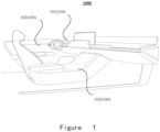
Figure 1 is a structural diagram of a vehicle in accordance with some embodiments of the present disclosure. -
Figure 2 is a structural diagram of an interior component in accordance with some embodiments of the present disclosure. -
Figure 3 is a structural diagram of an interior trim in accordance with some embodiments of the present disclosure. -
Figure 4 is a flow chart diagram of a method of manufacturing an interior trim for a vehicle in accordance with some embodiments of the present disclosure. -
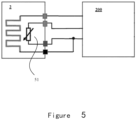
Figure 5 is a schematic diagram of control architecture of an ECU connected to an interior trim for a vehicle in accordance with some embodiments of the present disclosure. -
- 1000-vehicle
- 100- interior component
- 10 1-dashboard
- 102-door panel
- 1021- door panel insert
- 103-center console
- 10- interior trim
- 1- decorative layer
- 11- outer surface
- 12- inner surface
- 2- heating configuration
- 21- first heating layer
- 22- electrode
- 23- second heating layer
- 24- heating element
- 3- first isolating layer
- 4- second isolating layer
- 41-first glue layer
- 42-second glue layer
- 30- substrate
- 5-connector
- 5 1-protector
- 200- electronic control unit (ECU).
- The implementations of the present disclosure are described below by specific embodiments. Embodiment of the present disclosure from the contents disclosed in the description. Although the description of the present disclosure is introduced together with other embodiments, it does not mean that the features of the present disclosure are limited to the embodiments. On the contrary, the purpose of introducing the present disclosure in combination with the embodiments is to cover other embodiments that may be extended based on the claims of the present disclosure.
- It should be noted that in the following description, for example, "one embodiment", "an embodiment", and / or "some embodiments" refer to a feature, structure or characteristic related to at least one embodiment of the present disclosure. Therefore, it should be emphasized and noted that "an embodiment" or "one embodiment" or "one or more embodiments" mentioned twice or more in different positions in this specification do not necessarily refer to the same embodiment. In addition, some features, structures or characteristics in one or more embodiments of the present disclosure may be appropriately combined.
- Although the interior trim and interior component disclosed in the embodiments of the present disclosure are preferably applied to automobiles, they are not limited thereto. For example, they can also be applied to other vehicles, such as railway train, ship, and air plane, as long as they are vehicles, the interior trim and interior component disclosed in the embodiments of the present disclosure can be applied.
- In addition, compared with the current air-conditioning heating solution, the present disclosure improves the user experience and the heating efficiency, but it can be understood that this does not mean that vehicles equipped with the interior trim and interior component of the present disclosure cannot be equipped with heating air conditioners at the same time. For example, the interior trim and interior component of the present disclosure, as well as the heating air conditioner, can be set at the same time in a vehicle, and the interior trim and component parts of the present disclosure can correspondingly replace partial function of the heating air conditioner, to reduce energy consumption and further improve heating effect. The meaning of occupant described below is broad, that is, all persons in the vehicle are occupants, such as driver and passenger.
- Referring to
FIG. 1 , avehicle 1000, taking an automobile as an example, includes aninterior component 100, which may include, for example, adashboard 101, adoor panel 102, acenter console 103, etc. Currently, thedashboard 101 and thedoor panel 102 are generally of a split structure, and thedashboard 101 and thedoor panel 102 can be visually distinguished from each other. However, it is not excluded that the structures of thedashboard 101 and thedoor panel 102 are similar, forming an interior system of thevehicle 1000 in which thedashboard 101 and thedoor panel 102 form an integrated visual perception. - For an
interior trim 10 described in the following embodiments, taking thedoor panel 102 shown inFIG. 2 as an example, because the position corresponding to thedoor panel 102 is a position where the current vehicle air conditioner is difficult to fully heat, theinterior trim 10 is provided on the door panel so that the occupant can relatively feel more heating. Referring toFIG. 2 , in some embodiments, theinterior component 100 includes aninterior component body 101 and aninterior trim 10, and theinterior trim 10 is set on theinterior component body 101, and anouter surface 11 of adecorative layer 1 of theinterior trim 10 provides at least a portion of the surface of theinterior component 100. For example, as shown inFIG. 2 , theinterior trim 10 is located at thedoor panel insert 1021 of thedoor panel 102. - Referring to
FIG. 3 , in some embodiments, theinterior trim 10 includes adecorative layer 1 and aheating configuration 2 located on theinner surface 12 of thedecorative layer 1. The word "inner" and "outer" here, that is, one side of theinterior trim 10 close to the occupant is "outer", and the other side opposite to it is "inner". - The
decorative layer 1 has anouter surface 11 and aninner surface 12 opposite theouter surface 11. Theouter surface 11 is normally a surface on which theinterior trim 10 provides direct contact or direct visibility to the occupant. Thedecorative layer 1 is also defined as the outermost layer of theinterior trim 10, and normally serves to provide a directly visible decoration, so it is called a decorative layer. It can be understood that thedecorative layer 1 may be made of plastic, fabric, leather, artificial leather, metal, or the like, or may be made of a composite of the above materials, for example, leather plus a substrate, such as commonly used artificial leather (PVC/PU/TPU, etc.) plus a substrate fabric with a total thickness of about 1.1 mm, or leather plus foam with a thickness of about 3 mm. The materials mentioned are used as examples only and are not intended to imply any limitations on certain materials, for example, additional treatments such as softening, polishing, corrosion-resistant coating, etc. can also be applied to the said materials. Thedecorative layer 1 may be flexible and thus can be overlaid on any 3D structure. - The
heating configuration 2 includes afirst heating layer 21, anelectrode 22, and asecond heating layer 23, and theheating configuration 2 is located on theinner surface 12 of thedecorative layer 1, and thefirst heating layer 21 and thesecond heating layer 23 both include aheating element 24 extending in the plane of the heating layer, and theheating element 24 is made of a heating carbon material. Thefirst heating layer 21 and thesecond heating layer 23 are directly connected with theelectrode 22 on its outer side and inner side respectively to fix theelectrode 22, and thefirst heating layer 21, theelectrode 22 and thesecond heating layer 23 form a sandwich structure. - The heating carbon material here refers to a material that heats through the following principles: under the condition of electrification, carbon molecules produce atoms, ions and electrons, and friction and collision between carbon molecular groups (also known as Brownian motion) generate thermal energy, and the thermal energy is radiated through far-infrared rays with a wavelength of 5-14 microns. The heating carbon material may be a carbon material such as carbon nanotubes, carbon fibers, graphene, graphite, and carbon black. In some embodiments, the heating carbon material may include at least one of carbon nanotubes, carbon fibers, and graphene, and the carbon nanotubes may be in the form of single-walled carbon nanotubes, multi-walled carbon nanotubes, etc., and the carbon nanotubes, carbon fibers, and graphene may also be carbon materials having doped atoms. The beneficial effect of adopting at least one of carbon nanotubes, carbon fibers, and graphene is that the conductivity is better, the heat generation performance is more stable, and the electrothermal conversion efficiency is higher. Compared with traditional carbon materials, it has the characteristics of large power per unit area and high energy efficiency, which can make the heating configuration downsized and reduce energy consumption.
- Detailed process by which the
heating element 24 is made of the heating carbon material may be process by coating a slurry having the heating carbon material, and the slurry normally including a solvent, a heating carbon material ink, a dispersant, a binder, and other additives, with the mass percentages of each component selected on a case-by-case basis. The process of coating slurry may be a screen-printing process, but it is not limited to this. For example, it may also be realized by a coating process such as ultrasonic spraying. - The
first heating layer 21 and thesecond heating layer 22 includeheating element 24 extending in the plane of the heating layer, meaning thatheating element 24 extends at least partially in the plane of the heating layer. Thefirst heating layer 21 and thesecond heating layer 22 may be decorative by screen printing to form circuits having different visual shapes of figures, patterns, signs, words, images or symbols, or other decorative elements. Normally speaking, the graphic part of the screen printing is opaque, and the non-graphic part is transparent. - The sandwich-like structure formed by the
first heating layer 21, theelectrode 22, and thesecond heating layer 23 means that theelectrode 22 is also a part that occupies a certain thickness space, and is fixed by thefirst heating layer 21 and thesecond heating layer 23 directly connected outside and inside, so that theelectrode 22 can be in a stable and reliable contact with thefirst heating layer 21 and thesecond heating layer 23, and thefirst heating layer 21 and thesecond heating layer 23 can be stably and reliably energized and excited. Especially in the operating scene of the vehicles facing certain vibration conditions, stably and reliably run is particularly important. In addition, because theelectrode 22 is fixed on both sides by thefirst heating layer 21 and thesecond heating layer 23, theelectrode 22 itself can use a relatively low-cost part, such as a copper wire mesh, instead of using a relatively expensive silver part, nor a process of forming the electrode by a silver screen printing, but only needs to directly arrange a prepared copper wire mesh on thefirst heating layer 21, and then perform a covering process of thesecond heating layer 23. In some embodiments, theheating element 24 of thefirst heating layer 21 is attached to theinner surface 12 side of thedecorative layer 1 by screen printing; and theheating element 24 of thesecond heating layer 23 is attached to theelectrode 22 by screen printing, and thefirst heating layer 21 and thesecond heating layer 23 can be fixed more reliably, and the shapes of thefirst heating layer 21 and thesecond heating layer 22 can be set by screen printing. - It can be seen from the above that the
interior trim 10 and theinterior component 100 described in the above embodiments have a beneficial effect that by using a heating element formed of a slurry of a heating carbon material as a heating layer, high-efficiency heating is realized, the heating of the interior trim is realized to provide a heating effect, and the heating effect can be provided to the parts of the occupant where the thermal air flow is difficult to reach. And it can reduce the dryness that the occupants feel similar to the heating of the air conditioner. In addition, the heating configuration include the first heating layer, the electrode and the second heating layer to form a sandwich-like structure, to realize the electrode to be manufactured at a low cost and be fixed stably, and the electrode can be stably and reliably contacted with the heating layer to stimulate the heating layer, and the manufacturing cost of the interior trim is low at the same time is able to provide reliable heating. - As shown in
FIG. 3 , in some embodiments, in a structure which theheating configuration 2 is located on theinner surface 12 of thedecorative layer 1, a first isolatinglayer 3 may be provided between thefirst heating layer 21 at the outermost layer of theheating configuration 2 and theinner surface 12 of thedecorative layer 1 to isolate theheating configuration 2 from thedecorative layer 1. The first isolatinglayer 3 is provided to prevent thedecorative layer 1 from being stretched too much, and at the same time to prevent imprints on the outer surface of thedecorative layer 1 caused by coating different slurries. It can be understood that the first isolatinglayer 3 is not essential to be set, and if thedecorative layer 1 itself is not sensitive to the tensile effect caused by theheating configuration 2 and the imprint caused by the coating, for example, the thermal expansion coefficient of thedecorative layer 1 is small, and the color of thedecorative layer 1 itself is darker, and thefirst heating layer 21 can be directly covered on theinner surface 12 of thedecorative layer 1 by a process such as screen printing, spraying, etc. - Continuing with reference to
FIG. 3 , in some embodiments, theinterior trim 10 may also include asubstrate 30 set on the inner side ofheating configuration 2, to support theheating configuration 2. Thesubstrate 30 may be made of thermoplastic or rigid plastic polymers, including PET, MMA, PC, PU, ABS, PP, NFPP, etc. The thickness of thesubstrate 30 may be between 1 mm and 5 mm, in some embodiments between 2 mm and 2.5 mm. In some embodiments, theinterior trim 10 may also include a second isolating layer 4 located between thesecond heating layer 23 and thesubstrate 30 to isolate thesecond heating layer 23 and thesubstrate 30, and the second isolating layer 4 may be adhered to thesecond heating layer 23 and thesubstrate 30 respectively through afirst glue layer 41 and asecond glue layer 42. The second isolating layer 4 may be a spacer fabric material, such as a composite fiber material (including synthetic fibers and natural fibers), or a material such as a felt. The second isolating layer is, in some embodiments, made of a material with better thermal insulation performance, to provide a protective effect, and at the same time to reduce heat loss caused by heat transfer to the inner side of theinterior trim 10, that is, to the side of thesubstrate 30, to improve the thermal efficiency of theheating configuration 2. - Referring to
FIG. 3 andFIG. 5 , theinterior trim 10 may also include aconnector 5 connecting theelectrode 22 for electronically connecting to an electronic control unit (ECU) 200 to control the temperature of theheating configuration 2. Theconnector 5 is electronically connected to thecontrol unit 200 to transmit and receive signals and control the heating function. Thecontrol unit 200 controls the temperature provided by theheating configuration 2 within a predetermined threshold of about 50 °C, which approximately corresponds to the heating temperature of the carbon nanotube. In this way, theouter surface 11 of thedecorative layer 1 can provide a comfortable temperature for the occupants, and the occupants will not have a burn feeling even when they accidentally touch theouter surface 11. And it is possible to detect and ensure that the temperature of theinterior trim 10 does not exceed a predetermined threshold value by providing aprotector 51. When the detected temperature is higher than a predetermined threshold value, theprotector 51 disconnects the circuit between theelectrode 22 and thecontrol unit 200, or theprotector 51 changes its own resistance value to adjust the current and voltage distributed to the heating element, thereby affecting the power of the heating element. At least one of the NTC sensor and the PTC sensor may be selected as a selection for theprotector 51. It can be understood that thecontrol unit 200 herein may be spatially thecontrol unit 200 located near theinterior trim 10, or be integrated in thecontrol unit 200 of the whole vehicle, and it is not excluded that theelectrode 22 is wirelessly connected to thecontrol unit 200, in addition to being wirelessly connected through theconnector 5. The scheme of adopting theconnector 5 has the beneficial effect that the connection is more reliable. - It can be understood that flowcharts are used in the present disclosure to illustrate operations performed by the system according to embodiments of the present disclosure. It should be understood that, depending on the actual situation, the preceding or following operations are not necessarily performed precisely in order. One can also add additional steps to these procedures, or remove a step or steps from them.
- As described above, with reference to
FIG. 4 , in some embodiments, the steps of a method of manufacturing an interior trim for a vehicle may include: -
S 1. preparing adecorative layer 1;
For example, thedecorative layer 1 can be obtained by a process such as injection molding, or adecorative layer 1 can be obtained from a supplier. - S2. preparing a
first heating layer 21 on the inner side of thedecorative layer 1;
For example, as described above, using a screen-printed process to screen print the slurry having the heating carbon material on the inner side of thedecorative layer 1, which may be directly printed, or printed to the first isolatinglayer 3 on theinner surface 12 of thedecorative layer 1; - S3. setting an
electrode 22 to thefirst heating layer 21;
For example, as described above, theelectrode 22 is a copper wire mesh, and after the screen printing of thefirst heating layer 21 is completed, the copper wire mesh piece can be directly placed on the inner side of thefirst heating layer 21. - S4. Preparing a
second heating layer 23 to theelectrode 22 on its inner side. - For example, as described above, using a screen-printed process to screen print the slurry having the heating carbon material on the inner side of the
decorative layer 1, to form the sandwich-like structure of thefirst heating layer 21, theelectrode 22, and thesecond heating layer 23, and sufficient contact between the heating layer and the electrode and stable and reliable fixation are realized at a relatively low cost, and high heating efficiency of the interior trim is realized and a relatively comfortable heating experience for the user is realized. - In summary, using the interior trim, the interior component, and the manufacturing method described in the above embodiments have beneficial effects that, by using a heating element formed of a slurry of a heating carbon material as a heating layer, high-efficiency heating is realized, the heating of the interior trim is realized to provide a heating effect, and the heating effect can be provided to the parts of the occupant where the thermal air flow is difficult to reach. And it can reduce the dryness that the occupants feel similar to the heating of the air conditioner. In addition, the heating configuration include the first heating layer, the electrode and the second heating layer to form a sandwich-like structure, to realize the electrode to be manufactured at a low cost and be fixed stably, and the electrode can be stably and reliably contacted with the heating layer to stimulate the heating layer, and the manufacturing cost of the interior trim is low at the same time is able to provide reliable heating.
- Although the above embodiments of the present disclosure are disclosed as above, they are not used to limit the present disclosure. Therefore, any amendments, equivalent changes and modifications made to the above embodiments according to the essence of the present disclosure without departing from the proposal of the present disclosure fall within the scope of protection defined in the claims of the present disclosure.
Claims (10)
- An interior trim (10) for a vehicle, characterized in that it comprises:a decorative layer (1) having an outer surface (11) and an inner surface (12); anda heating configuration (2) comprising a first heating layer (21), an electrode (22), and a second heating layer (23), and the heating configuration (2) is located on the inner surface (12) of the decorative layer (1); wherein the first heating layer (21) and the second heating layer (23) both comprise a heating element (21) extending in the plane of the heating layer, and the heating element (21) is made of heating carbon material; and the first heating layer (21) and the second heating layer (23) are connected with the electrode (22) on its outer side and inner side respectively to fix the electrode (22), and the he first heating layer (21), the electrode (22) and the second heating layer (23) form a sandwich-like structure.
- The interior trim (10) according to claim 1, characterized in that, the electrode (22) is a copper wire mesh.
- The interior trim (10) according to claim 1, characterized in that, the heating carbon material comprises at least one among carbon nanotube, carbon fiber, and graphene.
- The interior trim (10) according to claim 1, characterized in that, the heating element (24) of the first heating layer (21) is screen-printed on the inner surface (12) side of the decorative layer (1), and the heating element (24) of the second heating layer (23) is screen-printed on the electrode (22).
- The interior trim (10) according to claim 1, characterized in that, it further comprises a first isolating layer (3), and the first isolating layer (3) is located between the first heating layer (21) and the decorative layer (1), to isolate the first heating layer (21) and the decorative layer (1).
- The interior trim (10) according to claim 1, characterized in that, it further comprises a substrate (30), and the substrate (30) is set on the inner side of heating configuration (2), to support the heating configuration (2).
- The interior trim (10) according to claim 1, characterized in that, it further comprises a second isolating layer (4), and the second isolating layer (4) is located between the second heating layer (23) and the substrate (30), to isolate the second heating layer (23) and the substrate (30).
- The interior trim (10) according to claim 1, characterized in that, it further comprises a connector (5) connecting the electrode (22), and the connector (5) being connected to an ECU (200) to control the operation of the heating configuration (2).
- An interior component (100) for a vehicle, characterized in that it comprises: an interior component body (101) and the interior trim (10) according to any one of claims 1-8, wherein the interior trim (10) is set on the interior component body (101), and the outer surface (11) of the decorative layer (1) of the interior trim (10) provides at least part of a surface of the interior component (100).
- A method for manufacturing an interior trim (10) for a vehicle, characterized in that it comprises:preparing a decorative layer (1);preparing a first heat generating layer (21) on the inner side of the decoration layer (1);setting an electrode (22) to the first heating layer (21); andpreparing a second heating layer (23) to the electrode (22) on its inner side.
Applications Claiming Priority (1)
| Application Number | Priority Date | Filing Date | Title |
|---|---|---|---|
| CN202310708508.6A CN119142271A (en) | 2023-06-14 | 2023-06-14 | Interior trim panel for a vehicle, interior trim part and method of manufacturing |
Publications (2)
| Publication Number | Publication Date |
|---|---|
| EP4478836A2 true EP4478836A2 (en) | 2024-12-18 |
| EP4478836A3 EP4478836A3 (en) | 2025-01-08 |
Family
ID=91580727
Family Applications (1)
| Application Number | Title | Priority Date | Filing Date |
|---|---|---|---|
| EP24182227.9A Pending EP4478836A3 (en) | 2023-06-14 | 2024-06-14 | Interior trim for vehicle, interior component and method of manufacturing interior trim |
Country Status (3)
| Country | Link |
|---|---|
| US (1) | US20240416848A1 (en) |
| EP (1) | EP4478836A3 (en) |
| CN (1) | CN119142271A (en) |
Families Citing this family (4)
| Publication number | Priority date | Publication date | Assignee | Title |
|---|---|---|---|---|
| USD881095S1 (en) * | 2018-04-25 | 2020-04-14 | Jaguar Land Rover Limited | Vehicle instrument panel |
| JP1794852S (en) * | 2022-09-08 | 2025-04-01 | Air outlet for vehicle air conditioner | |
| JP1789106S (en) * | 2023-06-05 | 2025-01-16 | Dashboard with clock module | |
| USD1077704S1 (en) * | 2024-05-17 | 2025-06-03 | Dcd Group Corp. | Dashboard for vehicle |
Family Cites Families (3)
| Publication number | Priority date | Publication date | Assignee | Title |
|---|---|---|---|---|
| KR101737693B1 (en) * | 2015-07-02 | 2017-05-18 | 구각회 | Film type heating element with low power comsumption for highly intense heating |
| FR3116474B1 (en) * | 2020-11-20 | 2024-11-22 | Faurecia Interieur Ind | Packing element comprising a heating element made of a carbon material |
| FR3116473B1 (en) * | 2020-11-20 | 2024-11-22 | Faurecia Interieur Ind | Packing element comprising a heating element and a proximity sensor |
-
2023
- 2023-06-14 CN CN202310708508.6A patent/CN119142271A/en active Pending
-
2024
- 2024-06-14 US US18/744,201 patent/US20240416848A1/en active Pending
- 2024-06-14 EP EP24182227.9A patent/EP4478836A3/en active Pending
Also Published As
| Publication number | Publication date |
|---|---|
| CN119142271A (en) | 2024-12-17 |
| EP4478836A3 (en) | 2025-01-08 |
| US20240416848A1 (en) | 2024-12-19 |
Similar Documents
| Publication | Publication Date | Title |
|---|---|---|
| EP4478836A2 (en) | Interior trim for vehicle, interior component and method of manufacturing interior trim | |
| CN101678737B (en) | vehicle heating system | |
| US10875430B2 (en) | Vehicle interior assemblies having leather cover with electrically conductive coating | |
| US10705666B2 (en) | Vehicle interior component with user interface | |
| US20140152057A1 (en) | Heated headrest | |
| JP6697215B2 (en) | Car door trim | |
| WO2020028755A1 (en) | Suspension fabric seat heating system | |
| JP6874225B2 (en) | Capacitive coupling sensor | |
| US20250042224A1 (en) | Heating device for vehicle interior | |
| JP7591644B2 (en) | Vehicle cockpit components with improved heating arrangements | |
| JP2010111250A (en) | Automobile heater and automobile with the same | |
| DE102023122759A1 (en) | INTERIOR PANEL FOR MOTOR VEHICLES AND MOTOR VEHICLES INCLUDING SUCH INTERIOR PANEL | |
| JP6858097B2 (en) | Vehicle armrests | |
| US20240149634A1 (en) | Vehicular Temperature Regulating System and Panel Assembly Including a Touch Panel Configured to be Heated or Cooled within a Passenger Compartment of a Vehicle | |
| CN207902125U (en) | Door shield handrail with heating function and vehicle | |
| US12202382B2 (en) | Occupancy sensing device, occupancy sensing and heating mat, and vehicle seat | |
| KR102696022B1 (en) | Heating element for car interior material | |
| CN206067572U (en) | A kind of automotive seat intelligent heating control system | |
| JP2019038345A (en) | Vehicle armrest | |
| CN212124791U (en) | Automobile heating device | |
| CN213565552U (en) | Electric automobile graphite alkene carpet heating system that generates heat | |
| CN112824213A (en) | Heated vehicle steering wheel with heat conduction function | |
| CN217496267U (en) | Ceiling structure of vehicle and vehicle | |
| CN220974089U (en) | Thermochromic interior trim of vehicle, A-pillar interior trim panel and vehicle | |
| CN223720602U (en) | A heating and defrosting system for the passenger compartment of an electric vehicle |
Legal Events
| Date | Code | Title | Description |
|---|---|---|---|
| PUAI | Public reference made under article 153(3) epc to a published international application that has entered the european phase |
Free format text: ORIGINAL CODE: 0009012 |
|
| STAA | Information on the status of an ep patent application or granted ep patent |
Free format text: STATUS: THE APPLICATION HAS BEEN PUBLISHED |
|
| PUAL | Search report despatched |
Free format text: ORIGINAL CODE: 0009013 |
|
| AK | Designated contracting states |
Kind code of ref document: A2 Designated state(s): AL AT BE BG CH CY CZ DE DK EE ES FI FR GB GR HR HU IE IS IT LI LT LU LV MC ME MK MT NL NO PL PT RO RS SE SI SK SM TR |
|
| AK | Designated contracting states |
Kind code of ref document: A3 Designated state(s): AL AT BE BG CH CY CZ DE DK EE ES FI FR GB GR HR HU IE IS IT LI LT LU LV MC ME MK MT NL NO PL PT RO RS SE SI SK SM TR |
|
| RIC1 | Information provided on ipc code assigned before grant |
Ipc: H05B 3/26 20060101ALI20241203BHEP Ipc: H05B 3/34 20060101ALI20241203BHEP Ipc: H05B 3/14 20060101AFI20241203BHEP |
|
| STAA | Information on the status of an ep patent application or granted ep patent |
Free format text: STATUS: REQUEST FOR EXAMINATION WAS MADE |
|
| 17P | Request for examination filed |
Effective date: 20250708 |
|
| RAP1 | Party data changed (applicant data changed or rights of an application transferred) |
Owner name: FAURECIA AUTOMOTIVE INTERIOR SYSTEM (SHANGHAI)CO., LTD. |
|
| STAA | Information on the status of an ep patent application or granted ep patent |
Free format text: STATUS: EXAMINATION IS IN PROGRESS |
|
| 17Q | First examination report despatched |
Effective date: 20251119 |