EP4478811A1 - Method and apparatus for switching gate control list in time-sensitive networking - Google Patents
Method and apparatus for switching gate control list in time-sensitive networking Download PDFInfo
- Publication number
- EP4478811A1 EP4478811A1 EP22927722.3A EP22927722A EP4478811A1 EP 4478811 A1 EP4478811 A1 EP 4478811A1 EP 22927722 A EP22927722 A EP 22927722A EP 4478811 A1 EP4478811 A1 EP 4478811A1
- Authority
- EP
- European Patent Office
- Prior art keywords
- gate control
- slot
- list
- control list
- resource block
- Prior art date
- Legal status (The legal status is an assumption and is not a legal conclusion. Google has not performed a legal analysis and makes no representation as to the accuracy of the status listed.)
- Pending
Links
Images




Classifications
-
- H—ELECTRICITY
- H04—ELECTRIC COMMUNICATION TECHNIQUE
- H04L—TRANSMISSION OF DIGITAL INFORMATION, e.g. TELEGRAPHIC COMMUNICATION
- H04L12/00—Data switching networks
- H04L12/28—Data switching networks characterised by path configuration, e.g. LAN [Local Area Networks] or WAN [Wide Area Networks]
- H04L12/40—Bus networks
- H04L12/407—Bus networks with decentralised control
- H04L12/417—Bus networks with decentralised control with deterministic access, e.g. token passing
-
- H—ELECTRICITY
- H04—ELECTRIC COMMUNICATION TECHNIQUE
- H04L—TRANSMISSION OF DIGITAL INFORMATION, e.g. TELEGRAPHIC COMMUNICATION
- H04L47/00—Traffic control in data switching networks
- H04L47/10—Flow control; Congestion control
- H04L47/28—Flow control; Congestion control in relation to timing considerations
-
- H—ELECTRICITY
- H04—ELECTRIC COMMUNICATION TECHNIQUE
- H04L—TRANSMISSION OF DIGITAL INFORMATION, e.g. TELEGRAPHIC COMMUNICATION
- H04L49/00—Packet switching elements
- H04L49/25—Routing or path finding in a switch fabric
- H04L49/253—Routing or path finding in a switch fabric using establishment or release of connections between ports
- H04L49/254—Centralised controller, i.e. arbitration or scheduling
-
- H—ELECTRICITY
- H04—ELECTRIC COMMUNICATION TECHNIQUE
- H04W—WIRELESS COMMUNICATION NETWORKS
- H04W72/00—Local resource management
- H04W72/04—Wireless resource allocation
Definitions
- This application relates to the field of communication technologies, and in particular, to a method and an apparatus for switching a gate control list in time-sensitive networking.
- time-sensitive networking time-sensitive-networking
- the TSN is a standard technology based on the standard Ethernet, provides deterministic information transmission, and provides reliable quality of service (quality of service, QoS) guarantee for the time-sensitive service.
- the TSN is a protocol cluster including a series of protocol standards, and each protocol implements a different function.
- the IEEE 802.1Qbv standard defines time-aware scheduling (time-aware scheduled, TAS) to ensure that information is delivered at the specified time.
- TAS time-aware scheduled
- a basic idea of time-aware scheduling is to use time division multiple access to divide Ethernet communication into fixed-length and repeated time slices, that is, periodic data transmission frames.
- the IEEE 802. 1Qbv further introduces a scheduling mechanism of a gate control operation, to implement orderly scheduling of a data frame by a TSN device.
- a gate control list (gate control list, GCL) is configured on a port of each TSN device.
- the gate control list includes a gate state and a slot, and transmission of a data frame is scheduled based on gate states in different slots (that is, gate control of a data stream).
- the IEEE 802. 1 Qbv standard supports gate control operations on a plurality of ports, each port supports two gate control lists, each gate control list supports 128 gate control slots, and each gate control slot occupies 32 bits (bit). Therefore, the gate control lists occupy a large amount of storage space. This causes an increase in a chip area.
- This application provides a method and an apparatus for switching a gate control list in time-sensitive networking, to help reduce resources occupied by gate control lists.
- an embodiment of this application provides a method for switching a gate control list in time-sensitive networking.
- the method may be implemented by a time-sensitive networking (time-sensitive-networking, TSN) device.
- the TSN device may include but is not limited to a device such as a switch or a vehicle-mounted gateway chip that supports the IEEE 802.1Qbv standard protocol and the extended protocol.
- a specific product type or product form of the TSN device is not limited in this embodiment of this application.
- Gate control slot storage space of the TSN device may include a first slot resource block and a second slot resource block, a quantity of slots in the first slot resource block is m times a quantity of slots in the second slot resource block, and m>1.
- the method may include:
- the TSN device may configure gate control slot storage space for gate control operations on all ports in a 1+1/m manner according to different storage space occupied by an idle-state gate control list and a running-state gate control list, and the idle-state gate control list and the running-state gate control list do not need to occupy same storage space.
- the list switching command includes a quantity of target slots required by the target port, and the establishing a first gate control list of the target port based on an idle slot in the first slot resource block and/or an idle slot in the second slot resource block and the list switching command includes: when the idle slot in the first slot resource block meets a first condition and/or the idle slot in the second slot resource block meets a second condition, establishing the first gate control list based on a preset list establishment policy and the quantity of target slots, where a quantity of slots included in the first gate control list is greater than or equal to the quantity of target slots.
- a condition and a list establishment policy may be preset for the TSN device, so that when switching the running-state gate control list of the target port based on a new running scenario, the TSN device may configure the idle-state gate control list by using an adapted list establishment policy based on the current scenario or a corresponding condition that the target port meets. This is convenient for the target port to switch the running-state gate control list.
- the TSN device may establish the first gate control list based on a preset list establishment policy, the quantity of target slots, and the different conditions that are met by the idle slot in the first slot resource block and/or the idle slot in the second slot resource block.
- the list establishment policy includes: when the gate control list switching times of the plurality of target ports are different, after establishing a first gate control list of a first target port in the plurality of target ports based on the gate control list switching times of the plurality of target ports and the idle slot in the second slot resource block, establishing a first gate control list of a second target port, where a gate control list switching time of the first target port is earlier than a gate control list switching time of the second target port.
- the list establishment policy may further include: when the gate control list switching times of the plurality of target ports are the same, after establishing a first part of a first gate control list of each target port based on the quantity of target slots of the plurality of target ports, establishing a second part of the first gate control list of each target port, where the first part includes a first quantity of slots in the first gate control list, the second part includes a second quantity of slots in the first gate control list, and a sum of the first quantity and the second quantity is greater than or equal to the quantity of target slots.
- the method may further include:
- the quantity of slots in the first slot resource block is greater than the quantity of slots in the second slot resource block.
- the TSN device monitors a slot occupied by the running-state gate control list of the target port, and runs the gate control list of the target port on the first slot resource block as much as possible, so that the slot in the second slot resource block is used as a temporary idle slot of each port of the entire TSN device, to maintain dynamical list switching by all ports of the TSN device.
- the third gate control list may be replaced with the second gate control list
- the first gate control list may be replaced with the fourth gate control list.
- the fourth gate control list is a gate control list that is of the target port and that is run before the second gate control list. That is, before obtaining the current list switching command, the TSN device may further perform the following steps when the fourth gate control list of the target port is in a running state and at least one slot included in the fourth gate control list includes a second slot in the second slot resource block: establishing a second gate control list of the target port based on the idle slot in the first slot resource block; and when the fourth gate control list is run in the second slot, switching the running-state gate control list of the target port to the second gate control list.
- the second gate control list may be used as an idle-state gate control list established for the target port indicated by a previous list switching command of the current list switching command, so that the running-state gate control list of the target port is switched from the fourth gate control list to the second gate control list.
- a running priority of a slot in the first slot resource block is higher than a running priority of a slot in the second slot resource block.
- a high running priority may be further assigned to a slot in the first slot resource block of the TSN device, and a low running priority may be assigned to a slot in the second slot resource block of the TSN device.
- the TSN device first establishes a link for the target port based on the idle slot in the first slot resource block, and establishes a link for the target port based on the idle slot in the second slot resource block when the idle slot in the first slot resource block is insufficient.
- the running-state gate control list of the target port runs in the slot in the first slot resource block as much as possible.
- the quantity of slots in the first slot resource block is n*m*k
- the quantity of slots in the second slot resource block is n*k, n, m, and k>1
- n represents a quantity of ports supported by the TSN device
- m represents a constant associated with a slot length
- k represents a quantity of slots included in a slot block.
- gate control slot storage space is provided for all ports based on a gate control protocol supported by the TSN device. Duration (a length of an associated slot) of each slot may be configured by a user, and a quantity of slots in a gate control list may also be configured by the user. A maximum of 128 gate control slots may be supported. This can provide a more flexible configuration method for the user, so that the user can apply a same TSN device to various service scenarios with different traffic scheduling requirements, to expand application scenarios of the TSN device.
- an embodiment of this application provides an apparatus for switching a gate control list in a time-sensitive networking, which may be used in a time-sensitive networking TSN device, and may be specifically used in a gate control logic module of the TSN device.
- Gate control slot storage space of the TSN device includes a first slot resource block and a second slot resource block, a quantity of slots in the first slot resource block is m times a quantity of slots in the second slot resource block, and m>1.
- the apparatus may include:
- the list switching command includes a quantity of target slots required by the target port
- the list establishment unit is configured to: when the idle slot in the first slot resource block meets a first condition and/or the idle slot in the second slot resource block meets a second condition, establish the first gate control list based on a preset list establishment policy and the quantity of target slots, where a quantity of slots included in the first gate control list is greater than or equal to the quantity of target slots.
- the first condition includes: a quantity of idle slots in the first slot resource block is greater than or equal to the quantity of target slots; and the list establishment policy includes: establishing the first gate control list based on the idle slot in the first slot resource block.
- the first condition includes: a quantity of idle slots in the first slot resource block is less than the quantity of target slots, and the second condition includes: a quantity of idle slots in the second slot resource block is greater than or equal to the quantity of target slots; and the list establishment policy includes: establishing the first gate control list based on the idle slot in the second slot resource block.
- the list switching command further includes gate control list switching times of the plurality of target ports
- the first condition includes: a quantity of idle slots in the first slot resource block is less than a sum of quantities of target slots of the plurality of target ports
- the second condition includes: a quantity of idle slots in the second slot resource block is less than a sum of quantities of target slots of the plurality of target ports.
- the list establishment policy includes: when the gate control list switching times of the plurality of target ports are different, after establishing a first gate control list of a first target port in the plurality of target ports based on the gate control list switching times of the plurality of target ports and the idle slot in the second slot resource block, establishing a first gate control list of a second target port, where a gate control list switching time of the first target port is earlier than a gate control list switching time of the second target port.
- the list establishment policy further includes: when the gate control list switching times of the plurality of target ports are the same, after establishing a first part of a first gate control list of each target port based on the quantity of target slots of the plurality of target ports, establishing a second part of the first gate control list of each target port, where the first part includes a first quantity of slots in the first gate control list, the second part includes a second quantity of slots in the first gate control list, and a sum of the first quantity and the second quantity is greater than or equal to the quantity of target slots.
- a running priority of a slot in the first slot resource block is higher than a running priority of a slot in the second slot resource block.
- the quantity of slots in the first slot resource block is n*m*k
- the quantity of slots in the second slot resource block is n*k, n, m, and k>1
- n represents a quantity of ports supported by the TSN device
- m represents a constant associated with a slot length
- k represents a quantity of slots included in a slot block.
- an embodiment of this application provides a time-sensitive networking device, which may include a processor, a gate control logic module, and a memory.
- the processor and the gate control logic module are coupled to the memory.
- the processor is configured to: execute a computer program or instructions stored in the memory, and send a list switching command to the gate control logic module.
- the gate control logic module is configured to execute the computer program or the instructions stored in the memory, so that the gate control logic module performs the method according to any one of the first aspect and the possible implementations of the first aspect.
- an embodiment of this application provides a computer-readable storage medium, including a program or instructions.
- the program or the instructions are executed, the method according to any one of the first aspect and the possible implementations of the first aspect is performed.
- this application provides an apparatus.
- the apparatus has a function of implementing the TSN device in the first aspect.
- the apparatus includes a module, a unit, or a means (means) corresponding to the steps performed by the TSN device in the first aspect.
- the function, the unit, or the means (means) may be implemented by software, or may be implemented by hardware, or may be implemented by hardware executing corresponding software.
- an embodiment of this application provides a computer program product.
- the computer When a computer reads and executes the computer program product, the computer is enabled to perform the method according to any one of the foregoing possible designs.
- an embodiment of this application provides a chip, configured to read and execute a software program stored in a memory, to implement the method according to any one of the foregoing possible designs.
- the memory is connected to the chip, or the memory is built in the chip.
- the chip further includes: a processor, configured to send a list switching command to the chip.
- the list switching command indicates a target port of the chip to switch a gate control list.
- the processor is connected to the chip, or the processor is built in the chip.
- a processor of the TSN device may configure two gate control lists for one port: a running-state gate control list (a running list for short) and a newly configured idle-state gate control list (an idle list for short).
- a running scenario changes, the processor configures a new gate control list based on a new scenario, and writes a new entry into the idle-state gate control list.
- Gate control logic of the TSN device performs switching based on a gate control list switching time configured by the processor, so that the port switches from the original running list to the idle list. After the switching is completed, the idle list is in a running state and becomes a running list. The original running list stops running and slots occupied by the list are released.
- a gate control list may include a gate state and a slot.
- the gate state may reflect a gate control switch state of a slot.
- the TSN device may schedule transmission of a data frame (that is, gate control on a data stream) based on gate states in different slots.
- a gate state is open (open)
- a data frame is allowed to be transmitted.
- a gate state is close (close)
- a data frame cannot be transmitted.
- a slot resource block is a storage resource provided by a memory of a TSN device, and is a general term of gate control slot storage space configured for implementing a gate control operation.
- a slot resource block includes several slot blocks, and each slot block may include k slots. For example, k may be 32.
- all ports of the TSN device may share the gate control slot storage space.
- the gate control slot storage space may be divided into two parts, which are represented as a first slot resource block and a second slot resource block. Configuration rules of the first slot resource block and the second slot resource block meet the following content:
- Embodiments of this application provide a method and an apparatus for switching a gate control list in time-sensitive networking (time-sensitive-networking, TSN), to help reduce resources occupied by gate control lists of the TSN device and maintain dynamical list switching by a port of the TSN device.
- TSN time-sensitive-networking
- the method and the device are based on a same technical concept. Because problem resolving principles of the method and the device are similar, for implementation of the device and the method, refer to each other, and repeated parts are not described again.
- a and/or B may represent the following cases: Only A exists, both A and B exist, and only B exists, where A and B may be singular or plural.
- the character "/” generally indicates that the related objects before and after are in an "or” relationship. At least one of the following items (pieces) or a similar expression thereof refers to any combination of these items, including any combination of singular items (pieces) or plural items (pieces).
- At least one item (piece) of a, b, or c may represent: a, b, c, a and b, a and c, b and c, or a, b, and c, where a, b, and c may be singular or plural.
- the singular expression forms “one”, “a”, “the”, “the foregoing”, “this”, and “the one” are also intended to include an expression form such as “one or more", unless the opposite is explicitly indicated in the context thereof.
- ordinal numbers such as “first” and “second” in embodiments of this application are for distinguishing between a plurality of objects, but are not intended to limit an order, a time sequence, priorities, or importance of the plurality of objects.
- a first gate control list and a second gate control list are merely intended to distinguish different gate control lists, but do not indicate two gate control lists have different priorities or different importance.
- FIG. 1 is a schematic diagram of a structure of a TSN device according to an embodiment of this application.
- the TSN device is a device that is sensitive to a non-fixed latency and jitter, and includes but is not limited to a device such as a switch or a vehicle-mounted gateway chip.
- the TSN device supports the IEEE802.1Qbv standard protocol and the extended protocol, and implements gate control on a data stream by performing gate control operations on a plurality of ports, to reduce a non-fixed latency and jitter of the data stream.
- the TSN device 100 may include a processor 110, a gate control logic module 120, and a memory 130.
- the processor 110 is usually a central processing unit (central processing unit, CPU), serves as an operation and control core of the TSN device 100, and is a final execution unit of information processing and program running.
- the processor 110 needs to configure a new gate control list for the new scenario, that is, write the gate control list.
- the processor 110 delivers a list switching command to the gate control logic module 120.
- the list switching command may indicate an identifier of a target port whose running-state gate control list needs to be switched, and slot information required by the new gate control list that needs to be established for the target port, for example, a quantity of target slots, a target slot length, a target gate state, and a target gate control list switching time.
- information included in the list switching command is merely an example for description rather than a limitation.
- the list switching command may alternatively include other information. Details are not described herein.
- a logic program used to implement a gate control operation specified in the protocol may be configured in the gate control logic module 120, or the logic program may be configured in the memory, and the gate control logic module 120 may run the logic program.
- the gate control logic module 120 When receiving the list switching command from the processor 110, the gate control logic module 120 performs, based on the related slot information indicated by the list switching command, a process of establishing an idle-state gate control list (also referred to as link establishment) for the target port.
- the process may be specifically as follows:
- the gate control logic module 120 applies to gate control slot storage space of the memory 130 for an idle slot block, links the applied slot blocks to form an idle slot linked list, and writes slot information into the linked slot blocks, to obtain the new gate control list of the target port.
- the new gate control list is in an idle state and includes at least one slot, and is a gate control list that the target port is to switch to and run.
- the new gate control list of the target port is referred to as a first gate control list.
- a current running-state gate control list of the target port is a second gate control list, and the second gate control list includes at least one slot.
- the gate control logic module 120 may switch a running-state gate control list of the target port from the second gate control list to the first gate control list, to further implement, based on the first gate control list, a gate control operation on a data stream passing through the target port.
- FIG. 2 is a schematic diagram of the gate control slot storage space of the TSN device according to an embodiment of this application. All ports of the TSN device may share the gate control slot storage space.
- the gate control slot storage space may be divided into two parts: a first slot resource block and a second slot resource block. A quantity of slots in the first slot resource block is greater than a quantity of slots in the second slot resource block.
- the gate control slot storage space of the TSN device may be, for example, random access memory (Random Access Memory, RAM) space
- the first slot resource block may be represented as RAMA
- the second slot resource block may be represented as RAMB.
- n represents a quantity of ports (Port number, Port_num for short) supported by the TSN device
- m represents a constant associated with a slot length
- the quantity of slots in the first slot resource block may be n*m*k, and the quantity of slots in the second slot resource block may be n*k, where n, m, and k>1.
- the quantity of slots in the first slot resource block is m times the quantity of slots in the second slot resource block.
- a value of m may be 4.
- the gate control logic module 120 may establish and run a gate control list for the target port based on a slot in the first slot resource block and/or a slot in the second slot resource block, to implement a gate control operation.
- a port 0 (PortO) is used as the target port.
- a running-state gate control list (a total of 128 slots are occupied, and a slot in the first slot resource block and/or a slot in the second slot resource block may be occupied) of the port 0, O indicates that a gate state of a slot is open (open), and C indicates that a gate state of a slot is close (close).
- the gate control logic module 120 performs a gate control operation on the port 0 based on the gate control list.
- the gate control list shows that the slot time3 is in a closed state.
- the data stream cannot be scheduled in the slot time3 that is currently in the closed state, and can be scheduled only in a slot time4 (an open state).
- the TSN device schedules the data stream at a fixed time, to reduce a non-fixed latency and jitter of the data stream.
- the gate control list After running in a slot time127 ends, the gate control list returns to a slot time0.
- duration (an associated slot length) of each slot may be configured by a user, and a quantity of slots in a gate control list may also be configured by the user.
- a maximum of 128 gate control slots may be supported.
- a running priority of a slot in the first slot resource block is higher than a running priority of a slot in the second slot resource block.
- the gate control logic module 120 applies to the second slot resource block RAMB for an idle slot, and uses an idle slot in the second slot resource block as a temporary idle slot of the first slot resource block. Temporarily running the first gate control list of the target port in the idle slot in the second slot resource block, to maintain dynamical list switching by the target port.
- the gate control logic module 120 performs switching to the first slot resource block for running the gate control list of the target port.
- the gate control logic module 120 may establish an idle-state gate control list for the target port based on a preset list establishment policy and the quantity of target slots.
- This embodiment of this application mainly relates to four switching scenarios.
- the logic program run by the gate control logic module 120 may establish an idle-state gate control list for the target port in the four switching scenarios, to implement a switching process of the running-state gate control list of the target port.
- the following describes in detail four main switching scenarios in this embodiment of this application.
- Example (1) a scenario in which idle slots in the first slot resource block are sufficient
- the first condition includes: a quantity of idle slots in the first slot resource block RAMA is greater than or equal to a quantity of target slots required by the target port.
- the list establishment policy includes: establishing the first gate control list based on the idle slot in the first slot resource block RAMA.
- the gate control logic module 120 may establish the first gate control list for the target port based on the idle slot in the first slot resource block. After the list switching condition is met, the gate control logic module 120 may switch the running-state gate control list of the target port from the second gate control list to the first gate control list, and release the previously running second gate control list, to complete list switching.
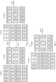
- a rectangular box filled with lines represents an occupied slot block in the RAMA, and a blank rectangular box represents an idle slot block in the RAMA (indicating that the slot block is not occupied by a gate control list of a port).
- a port 0 represents the target port, a running-state second gate control list of the port 0 is represented as RAMA 0->1->2->3, and currently runs in slot blocks 0 to 3 of the RAMA.
- Other slot blocks 4, 5, 9, 10, 171 to 175, and the like of the RAMA are occupied by other ports of the TSN device.
- Idle slot blocks at a current moment include 6 to 8, 11 to 14, and the like.
- a link is established based on an index pointer, and the index pointer is located in the slot block 9 at a previous index end moment, and backward indexing needs to be performed from the slot block 9.
- the gate control logic module 120 may write slot information of the new first gate control list into a corresponding slot linked list, to obtain the first gate control list, and wait for list switching.
- the list switching condition is met, the running-state gate control list of the target port port 0 is switched from the second gate control list RAMA 0->1->2->3 to the first gate control list RAMA 11->12->13, and the slot blocks 0, 1, 2, and 3 occupied by the second gate control list are released, to complete switching.
- the switching condition is met may be for example, running of the second gate control list ends, or a gate control list switching time arrives.
- a switching occasion of a gate control list is not limited in this embodiment of this application.
- a link establishment manner is not limited to an index pointer manner. This is not limited in this embodiment of this application. Details are not described in other scenarios below.
- Example (2) A scenario in which idle slots in the first slot resource block are insufficient and idle slots in the second slot resource block are sufficient
- the first condition includes: a quantity of idle lots in the first slot resource block is less than the target quantity of slots
- the second condition includes: a quantity of idle slots in the second slot resource block is greater than or equal to the quantity of target slots required by the target port.
- the list establishment policy includes: establishing the first gate control list based on an idle slot in the second slot resource block.
- the gate control logic module 120 may run, in the idle slot in the second slot resource block, the first gate control list established for the target port. After the list switching condition is met, the gate control logic module 120 may switch the running-state module list of the target port from the second gate control list to the first gate control list, and release slots occupied by the second gate control list.
- the gate control logic module 120 may further establish a third gate control list of the target port based on the idle slot in the first slot resource block RAMA, write slot information of the first gate control list running on the second slot resource block RAMB into a slot block corresponding to the third gate control list, switch from the first gate control list to the third gate control list after running of the first gate control list ends, and release slots occupied by the first gate control list, to complete switching.
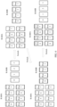
- a rectangular box filled with lines represents an occupied slot block in the RAMA and the RAMB, and a blank rectangular box represents an idle slot block in the RAMA and the RAMB (indicating that the slot block is not occupied by a gate control list of a port).
- the port 0 represents the target port
- the second gate control list (that is, an old gate control list) of the port 0 is represented as RAMA 0->1->2->3, and currently runs on slot blocks 0 to 3 of the RAMA, and other slot blocks 4 to 175 of the RAMA are occupied by other ports of the TSN device.
- the RAMA does not have sufficient storage space for the target port port 0 to establish a link, and a link needs to be established in the RAMB.
- Index numbers of idle slot blocks in the RAMB are 6 and 8.
- a link is established based on an index pointer. The index pointer is located in a slot block 4 at a previous index end moment, and backward indexing needs to be performed from the slot block 4.
- the gate control logic module 120 executes the list switching command, so that the running-state gate control list of the target port port 0 is switched from the second gate control list RAMA 0->1->2->3 to the first gate control list RAMB 6->8, and release the slot blocks 0, 1, 2, and 3 occupied by the second gate control list in the RAMA.
- the gate control logic module 120 establishes a third gate control list RAMA 0-> 1 in the RAMA based on the idle slot blocks 0, 1, 2, and 3, writes the slot information of the first gate control list in the RAMB into the RAMA, switches from RAMB 6->8 to RAMA 0-> 1 for running after running of the first gate control list RAMB 6->8 ends, and releases the slot blocks RAMB 6 and RAMB 8 occupied by the first gate control list RAMB 6->8.
- Example (3) A scenario in which idle slots in the first slot resource block are insufficient, idle slots in the second slot resource block are insufficient, and gate control list switching times of a plurality of target ports are different
- the list switching command indicates a plurality of target ports, and the list switching command further indicates different gate control list switching times of the different target ports.
- the first condition includes: a quantity of idle slots in the first slot resource block is less than a sum of quantities of target slots of the plurality of target ports; and a second condition includes: a quantity of idle slots in the second slot resource block is less than a sum of quantities of target slots of the plurality of target ports.
- the list establishment policy includes: after a first gate control list of a first target port in the plurality of target ports is established based on the gate control list switching times of the plurality of target ports and based on an idle slot in the second slot resource block, establishing a first gate control list of a second target port. A gate control list switching time of the first target port is earlier than a gate control list switching time of the second target port.
- the gate control logic module 120 establishes the first gate control list of each of the plurality of target ports in a time segment based on the gate control list switching time of the plurality of target ports and the idle slot in the second slot resource block.
- the process may specifically include: based on a sequence of gate control list switching times of the plurality of target ports, the gate control logic module 120 may first establish, based on the idle slot in the second slot resource block, the first gate control list of the first target port whose gate control list switching time is earlier.
- the gate control logic module 120 establishes the first gate control list for the second target port based on the newly released idle slot block.
- a third gate control list may be further established for the first target port based on the released idle slot block, so that the gate control list of the first target port is switched back to the first slot resource block for running, and a slot occupied by the first gate control list of the first target port in the second slot resource block is released.
- rectangular boxes filled with lines represent occupied slot blocks in the RAMA and the RAMB, and blank rectangular boxes represent idle slot blocks in the RAMA and the RAMB (indicating that a slot block is not occupied by a gate control list of a port).
- One slot block simply represents a RAMA slot block/RAMB slot block occupied by a second gate control list of a target port, and port 0, port 1, port 2, port 3, port 4, port 5, port 6, and port 7 represent a plurality of target ports, second gate control lists of the ports 0 to 7 each currently run on slot blocks 0 to 7 in the RAMA.
- the processor 110 needs to establish, based on gate control list switching times of the plurality of target ports port 0 to port 7, new idle-state gate control lists for target ports whose running-state gate control lists need to be first switched, and write slot information of the new gate control lists.
- the processor 110 and the gate control logic module 120 may switch the running-state gate control lists for the plurality of target ports port 0 to port 7 based on time segments by using the following steps:
- the processor 110 may indicate the gate control list switching times of the plurality of target ports at the same time by using a same list switching command, or by using at least two list switching commands.
- Each list switching command indicates to switch running-state gate control lists of several target ports whose gate control list switching times are the same in the plurality of target ports.
- the gate control logic module 120 responds to the at least two list switching commands, to implement list switching of the plurality of target ports.
- a specific implementation of a list switching command in this scenario is not limited in this embodiment of this application.
- Example (4) A scenario in which idle slots in the first slot resource block are insufficient, idle slots in the second slot resource block are insufficient, and gate control list switching times of a plurality of target ports are the same
- the list switching command indicates a plurality of target ports, and the list switching command further indicates that gate control list switching times of the plurality of target ports are the same.
- the first condition includes: a quantity of idle slots in the first slot resource block is less than a sum of quantities of target slots of the plurality of target ports; and a second condition includes: a quantity of idle slots in the second slot resource block is less than a sum of quantities of target slots of the plurality of target ports.
- the list establishment policy includes: after a first part of a first gate control list of each target port is established based on an idle slot in the second slot resource block, establishing a second part of the first gate control list of each target port.
- the first part includes a first quantity of slots in the first gate control list
- the second part includes a second quantity of slots in the first gate control list
- a sum of the first quantity and the second quantity is greater than or equal to the quantity of target slots.
- the gate control logic module 120 establishes the first part of the first gate control lists of the plurality of target ports based on the idle slot in the second slot resource block, and then establishes the second parts of the first gate control lists of the plurality of target ports after an idle slot is released from the first slot resource block or the second slot resource block.
- the gate control logic module 120 first writes slot information of the first part of the first gate control list that is first established for each target port into an idle slot block in the second slot resource block, to complete pre-switching. Further, after the switching starts, the gate control logic module 120 switches running-state gate control lists of the plurality of target ports from second gate control lists of the plurality of target ports to the first parts of the first gate control lists of the plurality of target ports for running in the RAMB, and releases slots occupied by the second gate control lists of the plurality of target ports in the first slot resource block.
- the gate control logic module 120 establishes links for the plurality of target ports in the first slot resource block based on a quantity of actual idle slots in the first slot resource block, and writes slot information of the second parts of the first gate control lists of the plurality of target ports into the idle slots in the first slot resource block.
- the second parts of the first gate control lists of the plurality of target ports are switched to the RAMA for running.
- the gate control logic module 120 writes, into the idle slot in the first slot resource block, slot information of the first parts that are of the first gate control lists of the plurality of target ports and that run in the second slot resource block, to complement the first gate control list. Then, after running of the first parts of the first gate control lists of the plurality of target ports in the RAMB ends, slots occupied by the first parts in the RAMB are released.
- An idle-state gate control list also needs to occupy 128 slots, and the running-state gate control lists of the port 0, the port 1, the port 2, and the port 3 need to be switched at a same gate control list switching time.
- the processor 110 and the gate control logic module 120 may switch the running-state gate control lists for the plurality of target ports port 0 to port 3 in batches by using the following steps:
- Example (1) to Example (4) List switching policies corresponding to different scenarios in a list switching mechanism of the TSN device in this embodiment of this application are described in detail by using Example (1) to Example (4).
- dynamically switching a running-state gate control list by a port of the TSN device can be maintained in reduced gate control slot storage space, to ensure service continuity of the TSN device.
- a data stream can be scheduled at a fixed time, to reduce a non-fixed delay and jitter of the data stream.
- a configurable slot duration, a configurable quantity of slots in a gate control list, and the like may further provide a more flexible configuration manner for a user, so that the user can apply a same TSN device to various service scenarios with different traffic scheduling requirements, to expand an application scenario of the TSN device.
- FIG. 8 is a schematic flowchart of a switching method according to an embodiment of this application. As shown in FIG. 8 , the switching method may include the following steps.
- the gate control logic module obtains a list switching command.
- the list switching command may be from the processor of the TSN device, and the list switching command may indicate a target port of the TSN device to switch a running-state gate control list.
- the list switching command may indicate an identifier of the target port and slot information required a new gate control list (for example, a first gate control list) that needs to be established for the target port, for example, a quantity of target slots, a target slot length, a target gate state, and a target gate control list switching time.
- a new gate control list for example, a first gate control list
- one list switching command may indicate one or more target ports.
- slot information of the plurality of target ports may be the same or may be different. This is not limited in this embodiment of this application. For details, refer to the foregoing detailed description with reference to Example (1) to Example (4). Details are not described herein again.
- the gate control logic module establishes the first gate control list of the target port based on an idle slot in the first slot resource block and/or an idle slot in the second slot resource block and the list switching command.
- the first gate control list is a new gate control list to which the target port needs to perform gate control list switching.
- the first gate control list is in an idle state, and the first gate control list may include at least one slot.
- the gate control logic module may apply, in response to the list switching command, to gate control slot storage space of the memory for one or more slot blocks required by the first gate control list, and link the applied slot blocks based on index numbers of the slot blocks, to complete a link establishment process of the first gate control list. Then, the slot information of the target port is written into each idle slot associated with the first gate control list.
- the list switching command may indicate information such as the quantity of target slots, the target slot length, and the target gate control list switching time of the first gate control list of the target port.
- the gate control logic module may establish the first gate control list for the target port according to a preset list establishment policy based on various information indicated by the list switching command and a condition that is met by the idle slot in the first slot resource block and/or the idle slot in the second slot resource block.
- the list switching condition is a condition that needs to be met by the target port to trigger switching from the running-state gate control list to the idle-state gate control list.
- the list switching condition may be that running of the second gate control list currently in a running state ends.
- the list switching condition may be that a gate control list switching time of the target port is reached.
- a switching occasion of the gate control list of the target port is not limited in this embodiment of this application.
- the second gate control list is a gate control list that is of the target port and that runs first
- the first gate control list is a gate control list that is of the target port and that runs after the second gate control list
- the running-state gate control list of the target port is switched to the first gate control list for running after running of the second gate control list runs.
- the gate control logic module When establishing a link for the first gate control list, the gate control logic module establishes a link based on several idle slot blocks, to obtain a slot linked list of the first gate control list, and then writes the slot information of the target port into each idle slot in the slot linked list. After the first gate control list is switched to the running state, the gate control logic module performs gate control on a data stream based on an index number, a gate state, a slot length, and the like of a slot block occupied by the first gate control list, to implement traffic scheduling.
- the second gate control list is originally in the running state and includes at least one slot.
- the list switching condition is met, switching is performed, and the running-state gate control list of the target port is switched from the second gate control list to the first gate control list.
- a running priority of a slot in the first slot resource block is higher than a running priority of a slot in the second slot resource block. If the first gate control list is in the running state, and the at least one slot included in the first gate control list includes a first slot in the second slot resource block, the slot that is in the second slot resource block and that is occupied by the first gate control list further needs to be switched to a slot in the first slot resource block. That is, the running-state gate control list of the target port occupies a slot in the first slot resource block as much as possible, and an idle slot in the second slot resource block temporarily runs the running-state gate control list of the target port only when idle slots in the first slot resource block are insufficient. When the first slot resource block has an idle slot, the running-state gate control list still needs to be switched back to the idle slot in the first slot resource block. Therefore, the switching method in this embodiment of this application may further include the following steps (not shown in the figure).
- the gate control logic module establishes a third gate control list of the target port based on the idle slot in the first slot resource block.
- Example (2) For a detailed implementation process, refer to the detailed description with reference to Example (2), Example (3), or Example (4). Details are not described herein again.
- An embodiment of this application further provides an apparatus for switching a gate control list in time-sensitive networking.
- the switching apparatus may be the gate control logic module shown in FIG. 1 .
- the processor and the gate control logic module are coupled to the memory.
- the processor is configured to: execute a computer program or instructions stored in the memory, and send a list switching command to the gate control logic module.
- the gate control logic module is configured to execute the computer program or the instructions stored in the memory, so that the gate control logic module performs the method in the foregoing embodiment.
- the switching apparatus 900 may include: an obtaining unit 901, configured to obtain the list switching command, where the list switching command indicates a target port of the TSN device to switch a running-state gate control list; a list establishment unit 902, configured to establish a first gate control list of the target port based on an idle slot in the first slot resource block and/or an idle slot in the second slot resource block and the list switching command; and a switching unit 903, configured to: when a list switching condition is met, execute the list switching command to switch the running-state gate control list of the target port from a second gate control list to the first gate control list.
- an obtaining unit 901 configured to obtain the list switching command, where the list switching command indicates a target port of the TSN device to switch a running-state gate control list
- a list establishment unit 902 configured to establish a first gate control list of the target port based on an idle slot in the first slot resource block and/or an idle slot in the second slot resource block and the list switching command
- a switching unit 903 configured to: when
- module division is an example, is merely logical function division, and may be other division during actual implementation.
- function modules in embodiments of this application may be integrated into one processor, or each of the modules may exist alone physically, or two or more modules may be integrated into one module.
- the integrated module may be implemented in a form of hardware, or may be implemented in a form of a software functional module.
- a TSN device 1000 may include a processor 1001, a memory 1002, a gate control logic module 1003, a communication interface 1004, and a bus 1005.
- Hardware of an entity corresponding to the switching apparatus may be the gate control logic module 1003.
- the processor 1001 may be a central processing module (central processing unit, CPU), a digital processing module, or the like.
- the memory 1002 is configured to: store a program executed by the processor 1001, provide storage space of a gate control logic module for the gate control logic module 1003, and the like.
- the memory 1002 may be a non-volatile memory, for example, a hard disk drive (hard disk drive, HDD) or a solid-state drive (solid-state drive, SSD), or may be a volatile memory (volatile memory), for example, a random access memory (random-access memory, RAM), or at least two of the foregoing memories.
- the memory 1002 is any other medium that can be used to carry or store expected program code in a form of instructions or a data structure and that can be accessed by a computer, but is not limited thereto.
- the processor 1001 may obtain, through the communication interface 1004, data collected by a sensor, data collected by a camera, and the like, to generate the list switching command.
- the gate control logic module 1003 may be configured to execute the program code stored in the memory 1002, and is specifically configured to perform the method described in the foregoing embodiment. For details, refer to the method described above with reference to the embodiments shown in FIG. 2 to FIG. 10 . Details are not described herein again in this application.
- a specific connection medium between the processor 1001, the memory 1002, the gate control logic module 1003, and the communication interface 1004 is not limited.
- the processor 1001, the memory 1002, the gate control logic module 1003, and the communication interface 1004 are connected through the bus 1005 in FIG. 10 .
- the bus is represented by a bold line in FIG. 10 .
- a connection manner between other components is merely an example for description, and is not limited thereto.
- the bus may be classified into an address bus, a data bus, a control bus, and the like. For ease of representation, only one thick line is used to represent the bus in FIG. 10 , but this does not mean that there is only one bus or only one type of bus.
- An embodiment of the present invention further provides a computer-readable storage medium, configured to store computer software instructions that need to be executed by the foregoing processor, and the computer-readable storage medium includes a program that needs to be executed by the foregoing processor.
- this application may be provided as a method, a system, or a computer program product. Therefore, this application may use a form of hardware only embodiments, software only embodiments, or embodiments with a combination of software and hardware. Moreover, this application may use a form of a computer program product that is implemented on one or more computer-usable storage media (including but not limited to a disk memory, a CD-ROM, an optical memory, and the like) that include computer usable program code.
- a computer-usable storage media including but not limited to a disk memory, a CD-ROM, an optical memory, and the like
- These computer program instructions may be provided for a general-purpose computer, a dedicated computer, an embedded processor, or a processor of any other programmable data processing apparatus to generate a machine, so that the instructions executed by a computer or a processor of any other programmable data processing apparatus generate an apparatus for implementing a specific function in one or more processes in the flowcharts and/or in one or more blocks in the block diagrams.
- These computer program instructions may also be stored in a computer-readable memory that can instruct the computer or any other programmable data processing apparatus to work in a specific manner, so that the instructions stored in the computer-readable memory generate an artifact that includes an instruction apparatus.
- the instruction apparatus implements a specific function in one or more processes in the flowcharts and/or in one or more blocks in the block diagrams.
- the computer program instructions may also be loaded onto a computer or another programmable data processing apparatus, so that a series of operations and steps are performed on the computer or the another programmable apparatus, to generate computer-implemented processing. Therefore, the instructions executed on the computer or the another programmable apparatus provide steps for implementing a specific function in one or more processes in the flowcharts and/or in one or more blocks in the block diagrams.
Landscapes
- Engineering & Computer Science (AREA)
- Computer Networks & Wireless Communication (AREA)
- Signal Processing (AREA)
- Data Exchanges In Wide-Area Networks (AREA)
Abstract
Description
- This application relates to the field of communication technologies, and in particular, to a method and an apparatus for switching a gate control list in time-sensitive networking.
- With the development of communication technologies, there is an increasing requirement for a scenario (for example, factory automation control and automatic driving) in which objects are used as communication bodies. This type of communication (which may also be referred to as a time-sensitive service) has an extremely high data transmission latency control requirement. Therefore, time-sensitive networking (time-sensitive-networking, TSN) emerges. The TSN is a standard technology based on the standard Ethernet, provides deterministic information transmission, and provides reliable quality of service (quality of service, QoS) guarantee for the time-sensitive service.
- The TSN is a protocol cluster including a series of protocol standards, and each protocol implements a different function. The IEEE 802.1Qbv standard defines time-aware scheduling (time-aware scheduled, TAS) to ensure that information is delivered at the specified time. A basic idea of time-aware scheduling is to use time division multiple access to divide Ethernet communication into fixed-length and repeated time slices, that is, periodic data transmission frames. The IEEE 802. 1Qbv further introduces a scheduling mechanism of a gate control operation, to implement orderly scheduling of a data frame by a TSN device. A gate control list (gate control list, GCL) is configured on a port of each TSN device. The gate control list includes a gate state and a slot, and transmission of a data frame is scheduled based on gate states in different slots (that is, gate control of a data stream).
- At present, the IEEE 802. 1 Qbv standard supports gate control operations on a plurality of ports, each port supports two gate control lists, each gate control list supports 128 gate control slots, and each gate
control slot occupies 32 bits (bit). Therefore, the gate control lists occupy a large amount of storage space. This causes an increase in a chip area. - This application provides a method and an apparatus for switching a gate control list in time-sensitive networking, to help reduce resources occupied by gate control lists.
- According to a first aspect, an embodiment of this application provides a method for switching a gate control list in time-sensitive networking. The method may be implemented by a time-sensitive networking (time-sensitive-networking, TSN) device. The TSN device may include but is not limited to a device such as a switch or a vehicle-mounted gateway chip that supports the IEEE 802.1Qbv standard protocol and the extended protocol. A specific product type or product form of the TSN device is not limited in this embodiment of this application.
- Gate control slot storage space of the TSN device may include a first slot resource block and a second slot resource block, a quantity of slots in the first slot resource block is m times a quantity of slots in the second slot resource block, and m>1. The method may include:
- obtaining a list switching command, where the list switching command indicates a target port of the TSN device to switch a running-state gate control list;
- establishing a first gate control list of the target port based on an idle slot in the first slot resource block and/or an idle slot in the second slot resource block and the list switching command, where the first gate control list is in an idle state, and the first gate control list includes at least one slot; and
- when a list switching condition is met, executing the list switching command to switch the running-state gate control list of the target port from a second gate control list to the first gate control list.
- In the foregoing method, total storage space occupied by one gate control list of all ports of the TSN device is considered as a whole. By controlling an establishment manner and a switching manner of a gate control list of a port of the TSN device, the TSN device may configure gate control slot storage space for gate control operations on all ports in a 1+1/m manner according to different storage space occupied by an idle-state gate control list and a running-state gate control list, and the idle-state gate control list and the running-state gate control list do not need to occupy same storage space. In such a 1+1 manner, gate control slot storage space is configured for two gate control lists (including a running-state gate control list and an idle-state gate control list) of all ports, so that resources occupied by the gate control lists can be reduced (for example, when m=4, storage space is reduced by about 37.5%), to maintain dynamical gate control list switching by the target port.
- With reference to the first aspect, in a possible implementation, the list switching command includes a quantity of target slots required by the target port, and the establishing a first gate control list of the target port based on an idle slot in the first slot resource block and/or an idle slot in the second slot resource block and the list switching command includes:
when the idle slot in the first slot resource block meets a first condition and/or the idle slot in the second slot resource block meets a second condition, establishing the first gate control list based on a preset list establishment policy and the quantity of target slots, where a quantity of slots included in the first gate control list is greater than or equal to the quantity of target slots. - According to the foregoing method, a condition and a list establishment policy may be preset for the TSN device, so that when switching the running-state gate control list of the target port based on a new running scenario, the TSN device may configure the idle-state gate control list by using an adapted list establishment policy based on the current scenario or a corresponding condition that the target port meets. This is convenient for the target port to switch the running-state gate control list.
- With reference to the first aspect, in a possible implementation, the TSN device may establish the first gate control list based on a preset list establishment policy, the quantity of target slots, and the different conditions that are met by the idle slot in the first slot resource block and/or the idle slot in the second slot resource block.
- Specifically, the following switching scenario may be included:
- (1) The first condition includes: a quantity of idle slots in the first slot resource block is greater than or equal to the quantity of target slots, and the list establishment policy includes: establishing the first gate control list based on the idle slot in the first slot resource block.
- (2) The first condition includes: a quantity of idle slots in the first slot resource block is less than the quantity of target slots, the second condition includes: a quantity of idle slots in the second slot resource block is greater than or equal to the quantity of target slots, and the list establishment policy includes: establishing the first gate control list based on the idle slot in the second slot resource block.
- (3) There are a plurality of target ports, the list switching command further includes gate control list switching times of the plurality of target ports, the first condition includes: a quantity of idle slots in the first slot resource block is less than a sum of quantities of target slots of the plurality of target ports, and the second condition includes: a quantity of idle slots in the second slot resource block is less than a sum of quantities of target slots of the plurality of target ports.
- The list establishment policy includes: when the gate control list switching times of the plurality of target ports are different, after establishing a first gate control list of a first target port in the plurality of target ports based on the gate control list switching times of the plurality of target ports and the idle slot in the second slot resource block, establishing a first gate control list of a second target port, where a gate control list switching time of the first target port is earlier than a gate control list switching time of the second target port.
- The list establishment policy may further include: when the gate control list switching times of the plurality of target ports are the same, after establishing a first part of a first gate control list of each target port based on the quantity of target slots of the plurality of target ports, establishing a second part of the first gate control list of each target port, where the first part includes a first quantity of slots in the first gate control list, the second part includes a second quantity of slots in the first gate control list, and a sum of the first quantity and the second quantity is greater than or equal to the quantity of target slots.
- According to the foregoing method, the TSN device may execute a corresponding list establishment policy based on a specific switching scenario, to complete a process of switching the gate control list of the target port, and flexibly maintain a dynamical list switching process.
- With reference to the first aspect, in a possible implementation, when the first gate control list is in a running state, and at least one slot included in the first gate control list includes a first slot in the second slot resource block, the method may further include:
- establishing a third gate control list of the target port based on the idle slot in the first slot resource block; and
- when the first gate control list is run in the first slot, switching the running-state gate control list of the target port to the third gate control list.
- According to the foregoing method, the quantity of slots in the first slot resource block is greater than the quantity of slots in the second slot resource block. The TSN device monitors a slot occupied by the running-state gate control list of the target port, and runs the gate control list of the target port on the first slot resource block as much as possible, so that the slot in the second slot resource block is used as a temporary idle slot of each port of the entire TSN device, to maintain dynamical list switching by all ports of the TSN device.
- It should be understood that in the foregoing process, the third gate control list may be replaced with the second gate control list, and the first gate control list may be replaced with the fourth gate control list. The fourth gate control list is a gate control list that is of the target port and that is run before the second gate control list. That is, before obtaining the current list switching command, the TSN device may further perform the following steps when the fourth gate control list of the target port is in a running state and at least one slot included in the fourth gate control list includes a second slot in the second slot resource block: establishing a second gate control list of the target port based on the idle slot in the first slot resource block; and when the fourth gate control list is run in the second slot, switching the running-state gate control list of the target port to the second gate control list. In other words, the second gate control list may be used as an idle-state gate control list established for the target port indicated by a previous list switching command of the current list switching command, so that the running-state gate control list of the target port is switched from the fourth gate control list to the second gate control list.
- With reference to the first aspect, in a possible implementation, a running priority of a slot in the first slot resource block is higher than a running priority of a slot in the second slot resource block.
- According to the foregoing method, there are a large quantity of slots in the first slot resource block, a high running priority may be further assigned to a slot in the first slot resource block of the TSN device, and a low running priority may be assigned to a slot in the second slot resource block of the TSN device. In this way, after obtaining the list switching command, the TSN device first establishes a link for the target port based on the idle slot in the first slot resource block, and establishes a link for the target port based on the idle slot in the second slot resource block when the idle slot in the first slot resource block is insufficient. The running-state gate control list of the target port runs in the slot in the first slot resource block as much as possible.
- With reference to the first aspect, in a possible implementation, the quantity of slots in the first slot resource block is n*m*k, the quantity of slots in the second slot resource block is n*k, n, m, and k>1, n represents a quantity of ports supported by the TSN device, m represents a constant associated with a slot length, and k represents a quantity of slots included in a slot block.
- According to the foregoing method, gate control slot storage space is provided for all ports based on a gate control protocol supported by the TSN device. Duration (a length of an associated slot) of each slot may be configured by a user, and a quantity of slots in a gate control list may also be configured by the user. A maximum of 128 gate control slots may be supported. This can provide a more flexible configuration method for the user, so that the user can apply a same TSN device to various service scenarios with different traffic scheduling requirements, to expand application scenarios of the TSN device.
- According to a second aspect, an embodiment of this application provides an apparatus for switching a gate control list in a time-sensitive networking, which may be used in a time-sensitive networking TSN device, and may be specifically used in a gate control logic module of the TSN device. Gate control slot storage space of the TSN device includes a first slot resource block and a second slot resource block, a quantity of slots in the first slot resource block is m times a quantity of slots in the second slot resource block, and m>1. The apparatus may include:
- an obtaining unit, configured to obtain a list switching command, where the list switching command indicates a target port of the TSN device to switch a running-state gate control list;
- a list establishment unit, configured to establish a first gate control list of the target port based on an idle slot in the first slot resource block and/or an idle slot in the second slot resource block and the list switching command, where the first gate control list is in an idle state, and the first gate control list includes at least one slot; and
- a switching unit, configured to: when a list switching condition is met, execute the list switching command to switch the running-state gate control list of the target port from a second gate control list to the first gate control list.
- With reference to the second aspect, in a possible implementation, the list switching command includes a quantity of target slots required by the target port, and the list establishment unit is configured to:
when the idle slot in the first slot resource block meets a first condition and/or the idle slot in the second slot resource block meets a second condition, establish the first gate control list based on a preset list establishment policy and the quantity of target slots, where a quantity of slots included in the first gate control list is greater than or equal to the quantity of target slots. - With reference to the second aspect, in a possible implementation, the first condition includes: a quantity of idle slots in the first slot resource block is greater than or equal to the quantity of target slots; and
the list establishment policy includes: establishing the first gate control list based on the idle slot in the first slot resource block. - With reference to the second aspect, in a possible implementation, the first condition includes: a quantity of idle slots in the first slot resource block is less than the quantity of target slots, and the second condition includes: a quantity of idle slots in the second slot resource block is greater than or equal to the quantity of target slots; and
the list establishment policy includes: establishing the first gate control list based on the idle slot in the second slot resource block. - With reference to the second aspect, in a possible implementation, there are a plurality of target ports, the list switching command further includes gate control list switching times of the plurality of target ports, the first condition includes: a quantity of idle slots in the first slot resource block is less than a sum of quantities of target slots of the plurality of target ports, and the second condition includes: a quantity of idle slots in the second slot resource block is less than a sum of quantities of target slots of the plurality of target ports.
- The list establishment policy includes: when the gate control list switching times of the plurality of target ports are different, after establishing a first gate control list of a first target port in the plurality of target ports based on the gate control list switching times of the plurality of target ports and the idle slot in the second slot resource block, establishing a first gate control list of a second target port, where a gate control list switching time of the first target port is earlier than a gate control list switching time of the second target port.
- With reference to the second aspect, in a possible implementation, the list establishment policy further includes: when the gate control list switching times of the plurality of target ports are the same, after establishing a first part of a first gate control list of each target port based on the quantity of target slots of the plurality of target ports, establishing a second part of the first gate control list of each target port, where the first part includes a first quantity of slots in the first gate control list, the second part includes a second quantity of slots in the first gate control list, and a sum of the first quantity and the second quantity is greater than or equal to the quantity of target slots.
- With reference to the second aspect, in a possible implementation, when the first gate control list is in a running state, and at least one slot included in the first gate control list includes a first slot in the second slot resource block, the list establishment unit is further configured to:
- establish a third gate control list of the target port based on the idle slot in the first slot resource block; and
- the switching unit is further configured to: when the first gate control list is run in the first slot, switch the running-state gate control list of the target port to the third gate control list.
- With reference to the second aspect, in a possible implementation, a running priority of a slot in the first slot resource block is higher than a running priority of a slot in the second slot resource block.
- With reference to the second aspect, in a possible implementation, the quantity of slots in the first slot resource block is n*m*k, the quantity of slots in the second slot resource block is n*k, n, m, and k>1, n represents a quantity of ports supported by the TSN device, m represents a constant associated with a slot length, and k represents a quantity of slots included in a slot block.
- According to a third aspect, an embodiment of this application provides a time-sensitive networking device, which may include a processor, a gate control logic module, and a memory. The processor and the gate control logic module are coupled to the memory. The processor is configured to: execute a computer program or instructions stored in the memory, and send a list switching command to the gate control logic module. The gate control logic module is configured to execute the computer program or the instructions stored in the memory, so that the gate control logic module performs the method according to any one of the first aspect and the possible implementations of the first aspect.
- According to a fourth aspect, an embodiment of this application provides a computer-readable storage medium, including a program or instructions. When the program or the instructions are executed, the method according to any one of the first aspect and the possible implementations of the first aspect is performed.
- According to a fifth aspect, this application provides an apparatus. The apparatus has a function of implementing the TSN device in the first aspect. For example, the apparatus includes a module, a unit, or a means (means) corresponding to the steps performed by the TSN device in the first aspect. The function, the unit, or the means (means) may be implemented by software, or may be implemented by hardware, or may be implemented by hardware executing corresponding software.
- According to a sixth aspect, an embodiment of this application provides a computer program product. When a computer reads and executes the computer program product, the computer is enabled to perform the method according to any one of the foregoing possible designs.
- According to a seventh aspect, an embodiment of this application provides a chip, configured to read and execute a software program stored in a memory, to implement the method according to any one of the foregoing possible designs. The memory is connected to the chip, or the memory is built in the chip.
- With reference to the seventh aspect, in a possible implementation, the chip further includes: a processor, configured to send a list switching command to the chip. The list switching command indicates a target port of the chip to switch a gate control list. The processor is connected to the chip, or the processor is built in the chip.
-
-
FIG. 1 is a schematic diagram of a structure of a TSN device according to an embodiment of this application; -
FIG. 2 is a schematic diagram of gate control slot storage space of a TSN device according to an embodiment of this application; -
FIG. 3 is a schematic diagram of a gate control list in a running state according to an embodiment of this application; -
FIG. 4 is a schematic diagram of a switching principle in a switching scenario according to an embodiment of this application; -
FIG. 5 is a schematic diagram of a switching principle in another switching scenario according to an embodiment of this application; -
FIG. 6 is a schematic diagram of a switching principle in another switching scenario according to an embodiment of this application; -
FIG. 7 is a schematic diagram of a switching principle in another switching scenario according to an embodiment of this application; -
FIG. 8 is a schematic flowchart of a switching method according to an embodiment of this application; -
FIG. 9 is a schematic diagram of a structure of a switching apparatus according to an embodiment of this application; and -
FIG. 10 is a schematic diagram of a structure of a TSN device according to an embodiment of this application. - The following first describes some terms in embodiments of this application, for ease of understanding by a person skilled in the art.
- (1) A gate control list is a list that records all gate control slot information of a port on a time-sensitive networking (time-sensitive-networking, TSN) device, and supports a maximum of 128 slots.
- Generally, a processor of the TSN device may configure two gate control lists for one port: a running-state gate control list (a running list for short) and a newly configured idle-state gate control list (an idle list for short). As a running scenario changes, the processor configures a new gate control list based on a new scenario, and writes a new entry into the idle-state gate control list. Gate control logic of the TSN device performs switching based on a gate control list switching time configured by the processor, so that the port switches from the original running list to the idle list. After the switching is completed, the idle list is in a running state and becomes a running list. The original running list stops running and slots occupied by the list are released.
- Generally, a gate control list may include a gate state and a slot. The gate state may reflect a gate control switch state of a slot. The TSN device may schedule transmission of a data frame (that is, gate control on a data stream) based on gate states in different slots. When a gate state is open (open), a data frame is allowed to be transmitted. When a gate state is close (close), a data frame cannot be transmitted.
- (2) A slot resource block is a storage resource provided by a memory of a TSN device, and is a general term of gate control slot storage space configured for implementing a gate control operation. Measured by a slot block, a slot resource block includes several slot blocks, and each slot block may include k slots. For example, k may be 32.
- In embodiments of this application, all ports of the TSN device may share the gate control slot storage space. The gate control slot storage space may be divided into two parts, which are represented as a first slot resource block and a second slot resource block. Configuration rules of the first slot resource block and the second slot resource block meet the following content:
- a. A slot in the first slot resource block preferentially runs a gate control list, and the second slot resource block is used to configure an idle list of a port when idle slots in the first slot resource block are insufficient.
- b. The slots included in the first slot resource block may exactly provide storage space of one gate control list for each port of the TSN device.
- c. To reduce resources occupied by two gate control lists of each port of the TSN device, a quantity of slots in the first slot resource block is configured to be greater than a quantity of slots in the second slot resource block. For example, the quantity of slots in the first slot resource block is m times the quantity of slots in the second slot resource block, where m is greater than 1. Therefore, the gate control slot storage space of the TSN device is reduced from 1+1 to 1+1/m, and this can save storage space for the TSN device.
- Embodiments of this application provide a method and an apparatus for switching a gate control list in time-sensitive networking (time-sensitive-networking, TSN), to help reduce resources occupied by gate control lists of the TSN device and maintain dynamical list switching by a port of the TSN device. The method and the device are based on a same technical concept. Because problem resolving principles of the method and the device are similar, for implementation of the device and the method, refer to each other, and repeated parts are not described again.
- It should be understood that, in the following embodiments, "and/or" describes an association relationship between associated objects and represents that three relationships may exist. For example, A and/or B may represent the following cases: Only A exists, both A and B exist, and only B exists, where A and B may be singular or plural. The character "/" generally indicates that the related objects before and after are in an "or" relationship. At least one of the following items (pieces) or a similar expression thereof refers to any combination of these items, including any combination of singular items (pieces) or plural items (pieces). For example, at least one item (piece) of a, b, or c may represent: a, b, c, a and b, a and c, b and c, or a, b, and c, where a, b, and c may be singular or plural. The singular expression forms "one", "a", "the", "the foregoing", "this", and "the one" are also intended to include an expression form such as "one or more", unless the opposite is explicitly indicated in the context thereof. In addition, unless otherwise stated, ordinal numbers such as "first" and "second" in embodiments of this application are for distinguishing between a plurality of objects, but are not intended to limit an order, a time sequence, priorities, or importance of the plurality of objects. For example, a first gate control list and a second gate control list are merely intended to distinguish different gate control lists, but do not indicate two gate control lists have different priorities or different importance.
- Referring to "an embodiment", "some embodiments", or the like in the specification of this application means that one or more embodiments of this application include a specific feature, structure, or characteristic described with reference to the embodiment. Therefore, in this specification, statements such as "in an embodiment", "in some embodiments", "in some other embodiments", and "in other embodiments" that appear at different places do not necessarily mean a same embodiment, but mean "one or more but not all of the embodiments", unless otherwise specified. The terms "include", "comprise", "have", and variants of the terms all mean "include but are not limited to", unless otherwise specifically emphasized.
-
FIG. 1 is a schematic diagram of a structure of a TSN device according to an embodiment of this application. The TSN device is a device that is sensitive to a non-fixed latency and jitter, and includes but is not limited to a device such as a switch or a vehicle-mounted gateway chip. The TSN device supports the IEEE802.1Qbv standard protocol and the extended protocol, and implements gate control on a data stream by performing gate control operations on a plurality of ports, to reduce a non-fixed latency and jitter of the data stream. - As shown in
FIG. 1 , theTSN device 100 may include aprocessor 110, a gatecontrol logic module 120, and amemory 130. - The
processor 110 is usually a central processing unit (central processing unit, CPU), serves as an operation and control core of theTSN device 100, and is a final execution unit of information processing and program running. When a running scenario changes, theprocessor 110 needs to configure a new gate control list for the new scenario, that is, write the gate control list. In this case, theprocessor 110 delivers a list switching command to the gatecontrol logic module 120. The list switching command may indicate an identifier of a target port whose running-state gate control list needs to be switched, and slot information required by the new gate control list that needs to be established for the target port, for example, a quantity of target slots, a target slot length, a target gate state, and a target gate control list switching time. It should be understood that, in this embodiment of this application, information included in the list switching command is merely an example for description rather than a limitation. In another embodiment, the list switching command may alternatively include other information. Details are not described herein. - A logic program used to implement a gate control operation specified in the protocol may be configured in the gate
control logic module 120, or the logic program may be configured in the memory, and the gatecontrol logic module 120 may run the logic program. - When receiving the list switching command from the
processor 110, the gatecontrol logic module 120 performs, based on the related slot information indicated by the list switching command, a process of establishing an idle-state gate control list (also referred to as link establishment) for the target port. The process may be specifically as follows: The gatecontrol logic module 120 applies to gate control slot storage space of thememory 130 for an idle slot block, links the applied slot blocks to form an idle slot linked list, and writes slot information into the linked slot blocks, to obtain the new gate control list of the target port. The new gate control list is in an idle state and includes at least one slot, and is a gate control list that the target port is to switch to and run. For ease of differentiation, in this embodiment of this application, the new gate control list of the target port is referred to as a first gate control list. - A current running-state gate control list of the target port is a second gate control list, and the second gate control list includes at least one slot. When a list switching condition is met, the gate
control logic module 120 may switch a running-state gate control list of the target port from the second gate control list to the first gate control list, to further implement, based on the first gate control list, a gate control operation on a data stream passing through the target port. -
FIG. 2 is a schematic diagram of the gate control slot storage space of the TSN device according to an embodiment of this application. All ports of the TSN device may share the gate control slot storage space. The gate control slot storage space may be divided into two parts: a first slot resource block and a second slot resource block. A quantity of slots in the first slot resource block is greater than a quantity of slots in the second slot resource block. - As shown in
FIG. 2 , the gate control slot storage space of the TSN device may be, for example, random access memory (Random Access Memory, RAM) space, the first slot resource block may be represented as RAMA, and the second slot resource block may be represented as RAMB. n represents a quantity of ports (Port number, Port_num for short) supported by the TSN device, m represents a constant associated with a slot length, and k represents a quantity of slots (for example, k=32, that is, each slot block includes 32 slots) included in a slot block (as shown in a rectangular box in the figure). The quantity of slots in the first slot resource block may be n*m*k, and the quantity of slots in the second slot resource block may be n*k, where n, m, and k>1. In other words, the quantity of slots in the first slot resource block is m times the quantity of slots in the second slot resource block. For example, a value of m may be 4. - The gate
control logic module 120 may establish and run a gate control list for the target port based on a slot in the first slot resource block and/or a slot in the second slot resource block, to implement a gate control operation. As shown inFIG. 3 , for example, a port 0 (PortO) is used as the target port. In a running-state gate control list (a total of 128 slots are occupied, and a slot in the first slot resource block and/or a slot in the second slot resource block may be occupied) of theport 0, O indicates that a gate state of a slot is open (open), and C indicates that a gate state of a slot is close (close). The gatecontrol logic module 120 performs a gate control operation on theport 0 based on the gate control list. When a data stream (including several data frames) arrives at an egress port scheduler (Egress Port Scheduler, EPS) of the TSN device in a slot (time) 3, the gate control list shows that the slot time3 is in a closed state. In this case, the data stream cannot be scheduled in the slot time3 that is currently in the closed state, and can be scheduled only in a slot time4 (an open state). In this way, the TSN device schedules the data stream at a fixed time, to reduce a non-fixed latency and jitter of the data stream. After running in a slot time127 ends, the gate control list returns to a slot time0. - In this embodiment of this application, duration (an associated slot length) of each slot may be configured by a user, and a quantity of slots in a gate control list may also be configured by the user. A maximum of 128 gate control slots may be supported. A running priority of a slot in the first slot resource block is higher than a running priority of a slot in the second slot resource block. After receiving the list switching command from the
processor 110, the gatecontrol logic module 120 preferentially applies to the first slot resource block RAMA for an idle slot. When a quantity of idle slots in the first slot resource block is insufficient to establish the first gate control list for the target port or is insufficient to establish the complete first gate control list for the target port, the gatecontrol logic module 120 applies to the second slot resource block RAMB for an idle slot, and uses an idle slot in the second slot resource block as a temporary idle slot of the first slot resource block. Temporarily running the first gate control list of the target port in the idle slot in the second slot resource block, to maintain dynamical list switching by the target port. When the first slot resource block has an idle slot, the gatecontrol logic module 120 performs switching to the first slot resource block for running the gate control list of the target port. - In this process, based on a first condition that an idle slot in the first slot resource block meets and/or a second condition that an idle slot in the second slot resource block meets, the gate
control logic module 120 may establish an idle-state gate control list for the target port based on a preset list establishment policy and the quantity of target slots. - This embodiment of this application mainly relates to four switching scenarios. The logic program run by the gate
control logic module 120 may establish an idle-state gate control list for the target port in the four switching scenarios, to implement a switching process of the running-state gate control list of the target port. The following describes in detail four main switching scenarios in this embodiment of this application. - In this scenario, the first condition includes: a quantity of idle slots in the first slot resource block RAMA is greater than or equal to a quantity of target slots required by the target port. The list establishment policy includes: establishing the first gate control list based on the idle slot in the first slot resource block RAMA.
- That is, the first slot resource block RAMA currently has sufficient idle slots, and can support running of the first gate control list of the target port. In this case, the gate
control logic module 120 may establish the first gate control list for the target port based on the idle slot in the first slot resource block. After the list switching condition is met, the gatecontrol logic module 120 may switch the running-state gate control list of the target port from the second gate control list to the first gate control list, and release the previously running second gate control list, to complete list switching. - As shown in
FIG. 4 , a rectangular box filled with lines represents an occupied slot block in the RAMA, and a blank rectangular box represents an idle slot block in the RAMA (indicating that the slot block is not occupied by a gate control list of a port). Each slot block includes k=32 slots. Aport 0 represents the target port, a running-state second gate control list of theport 0 is represented as RAMA 0->1->2->3, and currently runs inslot blocks 0 to 3 of the RAMA. Other slot blocks 4, 5, 9, 10, 171 to 175, and the like of the RAMA are occupied by other ports of the TSN device. Idle slot blocks at a current moment include 6 to 8, 11 to 14, and the like. In the RAMA, a link is established based on an index pointer, and the index pointer is located in theslot block 9 at a previous index end moment, and backward indexing needs to be performed from theslot block 9. - When the list switching command from the
processor 110 indicates that the quantity of target slots of thetarget port port 0 is 90, the gatecontrol logic module 120 needs to apply to the RAMA for three idle slot blocks (including a quantity of slots: 32+32+32=96, which is greater than 90) to establish a link for thetarget port port 0. Idle slot blocks in the RAMA are sufficient. Therefore, in this case, the gatecontrol logic module 120 may continue to perform backward indexing based on a current position in which the index pointer of the RAMA is located, and perform backward indexing from theslot block 9, to apply for three idle slot blocks after theslot block 9 for thetarget port port 0, for example, slot blocks whose index numbers are 11, 12, and 13 shown in the figure. A link establishment result of the slot blocks may be represented as: RAMA 11->12->13. In addition, the index pointer points to theslot block 14. - After link establishment is completed, the gate
control logic module 120 may write slot information of the new first gate control list into a corresponding slot linked list, to obtain the first gate control list, and wait for list switching. When the list switching condition is met, the running-state gate control list of thetarget port port 0 is switched from the second gate control list RAMA 0->1->2->3 to the first gate control list RAMA 11->12->13, and the slot blocks 0, 1, 2, and 3 occupied by the second gate control list are released, to complete switching. - It should be noted that, in this embodiment of this application, that the switching condition is met may be for example, running of the second gate control list ends, or a gate control list switching time arrives. A switching occasion of a gate control list is not limited in this embodiment of this application. In the first slot resource block or the second slot resource block of the gate control slot storage space, a link establishment manner is not limited to an index pointer manner. This is not limited in this embodiment of this application. Details are not described in other scenarios below.
- In this scenario, the first condition includes: a quantity of idle lots in the first slot resource block is less than the target quantity of slots, and the second condition includes: a quantity of idle slots in the second slot resource block is greater than or equal to the quantity of target slots required by the target port. The list establishment policy includes: establishing the first gate control list based on an idle slot in the second slot resource block.
- In other words, current idle slot blocks in the first slot resource block RAMA are insufficient, and cannot support running of the first gate control list of the target port. In this case, the gate
control logic module 120 may run, in the idle slot in the second slot resource block, the first gate control list established for the target port. After the list switching condition is met, the gatecontrol logic module 120 may switch the running-state module list of the target port from the second gate control list to the first gate control list, and release slots occupied by the second gate control list. Because the idle slots are released in the first slot resource block, the gatecontrol logic module 120 may further establish a third gate control list of the target port based on the idle slot in the first slot resource block RAMA, write slot information of the first gate control list running on the second slot resource block RAMB into a slot block corresponding to the third gate control list, switch from the first gate control list to the third gate control list after running of the first gate control list ends, and release slots occupied by the first gate control list, to complete switching. - As shown in
FIG. 5 , a rectangular box filled with lines represents an occupied slot block in the RAMA and the RAMB, and a blank rectangular box represents an idle slot block in the RAMA and the RAMB (indicating that the slot block is not occupied by a gate control list of a port). Each slot block includes k=32 slots. Theport 0 represents the target port, the second gate control list (that is, an old gate control list) of theport 0 is represented as RAMA 0->1->2->3, and currently runs onslot blocks 0 to 3 of the RAMA, andother slot blocks 4 to 175 of the RAMA are occupied by other ports of the TSN device. Currently, the RAMA does not have sufficient storage space for thetarget port port 0 to establish a link, and a link needs to be established in the RAMB. Index numbers of idle slot blocks in the RAMB are 6 and 8. In the RAMB, a link is established based on an index pointer. The index pointer is located in aslot block 4 at a previous index end moment, and backward indexing needs to be performed from theslot block 4. - When the list switching command from the
processor 110 indicates that the quantity of target slots of thetarget port port 0 is 50, the gatecontrol logic module 120 needs to apply to the RAMB for two idle slot blocks (including a quantity of slots: 32+32=64, which is greater than 50) to establish a link for thetarget port port 0. Idle slot blocks in the RAMB are sufficient. Therefore, in this case, the gatecontrol logic module 120 may continue to perform backward indexing based on a current position in which the index pointer of the RAMB is located, and perform backward indexing from theslot block 4, to apply for two idle slot blocks after theslot block 4 for thetarget port port 0, for example, slot blocks whose index numbers are 6 and 8 shown in the figure. A link establishment result of the slot blocks may be represented as: 6->8. In addition, the index pointer points to theslot block 9. After link establishment is completed, the gatecontrol logic module 120 may write slot information of the new first gate control list into a corresponding slot linked list, to obtain the first gate control list, and wait for list switching. - When the list switching condition is met, the gate
control logic module 120 executes the list switching command, so that the running-state gate control list of thetarget port port 0 is switched from the second gate control list RAMA 0->1->2->3 to the first gate control list RAMB 6->8, and release the slot blocks 0, 1, 2, and 3 occupied by the second gate control list in the RAMA. Then, the gatecontrol logic module 120 establishes a third gate control list RAMA 0-> 1 in the RAMA based on the idle slot blocks 0, 1, 2, and 3, writes the slot information of the first gate control list in the RAMB into the RAMA, switches from RAMB 6->8 to RAMA 0-> 1 for running after running of the first gate control list RAMB 6->8 ends, and releases the slot blocksRAMB 6 andRAMB 8 occupied by the first gate control list RAMB 6->8. - In this scenario, the list switching command indicates a plurality of target ports, and the list switching command further indicates different gate control list switching times of the different target ports.
- The first condition includes: a quantity of idle slots in the first slot resource block is less than a sum of quantities of target slots of the plurality of target ports; and a second condition includes: a quantity of idle slots in the second slot resource block is less than a sum of quantities of target slots of the plurality of target ports. The list establishment policy includes: after a first gate control list of a first target port in the plurality of target ports is established based on the gate control list switching times of the plurality of target ports and based on an idle slot in the second slot resource block, establishing a first gate control list of a second target port. A gate control list switching time of the first target port is earlier than a gate control list switching time of the second target port.
- That is, neither the first slot resource block nor the second slot resource block currently has sufficient idle slot blocks, and cannot support running of the first gate control lists of the plurality of target ports. In this case, the gate
control logic module 120 establishes the first gate control list of each of the plurality of target ports in a time segment based on the gate control list switching time of the plurality of target ports and the idle slot in the second slot resource block. - The process may specifically include: based on a sequence of gate control list switching times of the plurality of target ports, the gate
control logic module 120 may first establish, based on the idle slot in the second slot resource block, the first gate control list of the first target port whose gate control list switching time is earlier. When the running-state gate control list of the first target port is switched to the first gate control list of the first target port, running of the second gate control list of the first target port ends and an idle slot block is released. Further, the gatecontrol logic module 120 establishes the first gate control list for the second target port based on the newly released idle slot block. After the running-state gate control list of the second target port is switched to the first gate control list of the second target port, when running of the second gate control list of the second target port ends and an idle slot block is released, a third gate control list may be further established for the first target port based on the released idle slot block, so that the gate control list of the first target port is switched back to the first slot resource block for running, and a slot occupied by the first gate control list of the first target port in the second slot resource block is released. - As shown in
FIG. 6 , rectangular boxes filled with lines represent occupied slot blocks in the RAMA and the RAMB, and blank rectangular boxes represent idle slot blocks in the RAMA and the RAMB (indicating that a slot block is not occupied by a gate control list of a port). One slot block simply represents a RAMA slot block/RAMB slot block occupied by a second gate control list of a target port, andport 0,port 1,port 2,port 3,port 4,port 5,port 6, andport 7 represent a plurality of target ports, second gate control lists of theports 0 to 7 each currently run onslot blocks 0 to 7 in the RAMA. - Because there is no sufficient idle slot block in the RAMB to run first gate control lists of the
port 0 to theport 7, theprocessor 110 needs to establish, based on gate control list switching times of the plurality oftarget ports port 0 toport 7, new idle-state gate control lists for target ports whose running-state gate control lists need to be first switched, and write slot information of the new gate control lists. - For example, in
FIG. 6 , it is assumed that the gate control list switching times of theport 0 to theport 3 areearlier time 10, and the gate control list switching times of theport 4 to theport 7 are later time 20. Theprocessor 110 and the gatecontrol logic module 120 may switch the running-state gate control lists for the plurality oftarget ports port 0 toport 7 based on time segments by using the following steps: - (1) The
processor 110 delivers a list switching command to the gatecontrol logic module 120, to indicate the gate control list switching times time10 and time20 of theport 0 to theport 7. The gatecontrol logic module 120 first establishes first gate control lists for theport 0 to theport 3 based on idle slot blocks 0 to 3 in the second slot resource block RAMB according to the time10 and time20, and writes slot information of the first gate control lists of theport 0 to theport 3 to the idle slot blocks 0 to 3. - (2) When running of the second gate control lists of the
port 0 to theport 3 in the RAMA ends, theport 0 to theport 3 respectively switch from the second gate control listsRAMA 0,RAMA 1,RAMA 2, andRAMA 3 of theport 0 to theport 3 to the first gate control listsRAMB 0,RAMB 1,RAMB 2, andRAMB 3 of theport 0 to theport 3 for running, andRAMA 0,RAMA 1,RAMA 2, andRAMA 3 are released. In this case, the gatecontrol logic module 120 establishes first gate control lists for theport 4 to theport 7 based on the idleresource blocks RAMA 0,RAMA 1,RAMA 2, andRAMA 3 in the RAMA, and writes slot information of the first gate control lists of theport 4 to theport 7 into theRAMA 0,RAMA 1,RAMA 2, andRAMA 3. - (3) When running of the second gate control lists of the
Port 4 to thePort 7 in the RAMA ends, thePort 4 to thePort 7 respectively switch from the second gate control listsRAMA 4,RAMA 5,RAMA 6, andRAMA 7 of thePort 4 to thePort 7 to the first gate control listsRAMA 0,RAMA 1,RAMA 2, andRAMA 3 of thePort 4 to thePort 7 for running, and theRAMA 4,RAMA 5,RAMA 6, andRAMA 7 are released. In this case, the gatecontrol logic module 120 establishes third gate control lists for theport 0 to theport 3 based on the idleresource blocks RAMA 4,RAMA 5,RAMA 6, andRAMA 7 in the RAMA, and writes slot information of the third gate control lists of theport 0 to theport 3 into theRAMA 4,RAMA 5,RAMA 6, andRAMA 7. - (4) When running of the first gate control lists of the
port 0 to theport 3 in the RAMB ends, theport 0 to theport 3 respectively switches from the first gate control listsRAMB 0,RAMB 1,RAMB 2, andRAMB 3 to the third gate control listsRAMA 4,RAMA 5,RAMA 6, andRAMA 7, and theRAMB 0,RAMB 1,RAMB 2, andRAMB 3 are released. - At this point, switching of the gate control lists is completed for the
port 0 to theport 7 based on time segments. - It should be noted that, in a scenario in which the gate control list switching times of the plurality of target ports are different in Example (3), the
processor 110 may indicate the gate control list switching times of the plurality of target ports at the same time by using a same list switching command, or by using at least two list switching commands. Each list switching command indicates to switch running-state gate control lists of several target ports whose gate control list switching times are the same in the plurality of target ports. Further, the gatecontrol logic module 120 responds to the at least two list switching commands, to implement list switching of the plurality of target ports. A specific implementation of a list switching command in this scenario is not limited in this embodiment of this application. - In this scenario, the list switching command indicates a plurality of target ports, and the list switching command further indicates that gate control list switching times of the plurality of target ports are the same.
- The first condition includes: a quantity of idle slots in the first slot resource block is less than a sum of quantities of target slots of the plurality of target ports; and a second condition includes: a quantity of idle slots in the second slot resource block is less than a sum of quantities of target slots of the plurality of target ports. The list establishment policy includes: after a first part of a first gate control list of each target port is established based on an idle slot in the second slot resource block, establishing a second part of the first gate control list of each target port. The first part includes a first quantity of slots in the first gate control list, the second part includes a second quantity of slots in the first gate control list, and a sum of the first quantity and the second quantity is greater than or equal to the quantity of target slots.
- That is, neither the first slot resource block nor the second slot resource block currently has sufficient idle slot blocks, and cannot support simultaneous running of the first gate control lists of the plurality of target ports. In this case, the gate
control logic module 120 establishes the first part of the first gate control lists of the plurality of target ports based on the idle slot in the second slot resource block, and then establishes the second parts of the first gate control lists of the plurality of target ports after an idle slot is released from the first slot resource block or the second slot resource block. - The gate
control logic module 120 first writes slot information of the first part of the first gate control list that is first established for each target port into an idle slot block in the second slot resource block, to complete pre-switching. Further, after the switching starts, the gatecontrol logic module 120 switches running-state gate control lists of the plurality of target ports from second gate control lists of the plurality of target ports to the first parts of the first gate control lists of the plurality of target ports for running in the RAMB, and releases slots occupied by the second gate control lists of the plurality of target ports in the first slot resource block. - Further, the gate
control logic module 120 establishes links for the plurality of target ports in the first slot resource block based on a quantity of actual idle slots in the first slot resource block, and writes slot information of the second parts of the first gate control lists of the plurality of target ports into the idle slots in the first slot resource block. When running of the first parts of the first gate control lists of the plurality of target ports in the RAMB ends, the second parts of the first gate control lists of the plurality of target ports are switched to the RAMA for running. - Further, the gate
control logic module 120 writes, into the idle slot in the first slot resource block, slot information of the first parts that are of the first gate control lists of the plurality of target ports and that run in the second slot resource block, to complement the first gate control list. Then, after running of the first parts of the first gate control lists of the plurality of target ports in the RAMB ends, slots occupied by the first parts in the RAMB are released. - As shown in
FIG. 7 , rectangular boxes filled with lines represent occupied slot blocks in the RAMA and the RAMB, blank rectangular boxes represent idle slot blocks in the RAMA and the RAMB (indicating that a slot block is not occupied by a gate control list of a port), and one slot block represents 32 slots. It is assumed that m=4. Running-state gate control lists (that is, the second gate control list) of alltarget ports port 0,port 1,port 2, andport 3 occupy 128 slots, which are represented asport 0 0-3,port 1 0-3,port 2 0-3, andport 4 0-3. An idle-state gate control list also needs to occupy 128 slots, and the running-state gate control lists of theport 0, theport 1, theport 2, and theport 3 need to be switched at a same gate control list switching time. Theprocessor 110 and the gatecontrol logic module 120 may switch the running-state gate control lists for the plurality oftarget ports port 0 toport 3 in batches by using the following steps: - (1) The
processor 110 delivers a list switching command to the gatecontrol logic module 120, to indicate that the gate control list switching time of theport 0 to theport 3 is time10 and a quantity of target slots is 128. The gatecontrol logic module 120 first establishes first parts of the first gate control lists for theport 0 to theport 3 based on the gate control list switching time and the quantity of target slots of theport 0 to theport 3 and idle slot blocks 0 to 3 in the second slot resource block RAMB, and writes slot information of the first parts of the first gate control lists of theport 0 to theport 3 into the idle slot blocks 0 to 3 of the RAMB, to complete pre-switching. The first part of the first gate control list of each target port includes a first quantity of slots (for example, 32), and occupies a first slot block in the RAMB. The first parts of the first gate control lists of all thetarget ports port 0 toport 3 occupy all storage space of the RAMB, that is, 32*4=128. - (2) When list switching starts, the running-state gate control lists of the
target ports port 0 toport 3 are switched from the second gate control lists to the first gate control lists of thetarget ports port 0 toport 3, and the first parts (for example, the first 32 slots of each target port) of the first gate control lists of thetarget ports port 0 toport 3 are run in the RAMB. The second gate control lists of theport 0 to theport 3 are invalid, and slots occupied by the second gate control lists in the RAMA are released. - (3) The gate
control logic module 120 establishes the second parts of the first gate control lists of theport 0 to theport 3 based on the idle slot blocks in the RAMA. For example, each of the first gate control lists of theport 0 to theport 3 requires 128 slots. The gatecontrol logic module 120 applies to the RAMA for four slot blocks for theport 0 to theport 3, and writes slot information of the second parts of the first gate control lists of theport 0 to the port 3 (that is, remaining 96 slots of the first gate control list of each target port) into a linked list of idle slot blocks that are applied for and established in the RAMA. The second part of the first gate control list of each target port includes a second quantity of slots (for example, 96), and occupies a second slot block of the RAMA. The second parts of the first gate control lists of all thetarget ports port 0 toport 3 do not occupy all storage space of the RAMA. - (4) After running of the first parts of the first gate control lists of the
target ports port 0 to theport 3 in the RAMB ends, thetarget ports port 0 to theport 3 switch to the RAMA to run the second parts of the first gate control lists. In this case, the gatecontrol logic module 120 writes, into the RAMA, the slot information of the first part of the first gate control list that runs in the RAMB, to complement the first gate control list in the RAMA. Then, slots occupied by the first part of the first gate control list of each target port in the RAMB are released. - In this way, simultaneous switching of the gate control list of the plurality of
target ports port 0 toport 3 is implemented. - In this way, an establishment manner and a switching manner of a gate control list of a port of the TSN device are controlled, the TSN device may configure gate control slot storage space for all ports in a 1+1/m manner for gate control operations, and does not need to configure gate control slot storage space for two gate control lists (including a running-state gate control list and an idle-state gate control list) of each port in a 1+1 manner. This reduces resources occupied by gate control lists (for example, when m=4, about 37.5% of storage space is reduced).
- List switching policies corresponding to different scenarios in a list switching mechanism of the TSN device in this embodiment of this application are described in detail by using Example (1) to Example (4). In the switching mechanism, dynamically switching a running-state gate control list by a port of the TSN device can be maintained in reduced gate control slot storage space, to ensure service continuity of the TSN device. In addition, a data stream can be scheduled at a fixed time, to reduce a non-fixed delay and jitter of the data stream. In this solution, a configurable slot duration, a configurable quantity of slots in a gate control list, and the like may further provide a more flexible configuration manner for a user, so that the user can apply a same TSN device to various service scenarios with different traffic scheduling requirements, to expand an application scenario of the TSN device.
- Based on the switching scenarios, an embodiment of this application provides a method for switching a gate control list in a TSN network. The method may be implemented by the processor, the gate control logic module, and the memory in the TSN device shown in
FIG. 1 .FIG. 8 is a schematic flowchart of a switching method according to an embodiment of this application. As shown inFIG. 8 , the switching method may include the following steps. - S810: The gate control logic module obtains a list switching command.
- In this embodiment of this application, the list switching command may be from the processor of the TSN device, and the list switching command may indicate a target port of the TSN device to switch a running-state gate control list.
- In an optional implementation, the list switching command may indicate an identifier of the target port and slot information required a new gate control list (for example, a first gate control list) that needs to be established for the target port, for example, a quantity of target slots, a target slot length, a target gate state, and a target gate control list switching time.
- It may be understood that one list switching command may indicate one or more target ports. When one list switching command indicates a plurality of target ports, slot information of the plurality of target ports may be the same or may be different. This is not limited in this embodiment of this application. For details, refer to the foregoing detailed description with reference to Example (1) to Example (4). Details are not described herein again.
- S820: The gate control logic module establishes the first gate control list of the target port based on an idle slot in the first slot resource block and/or an idle slot in the second slot resource block and the list switching command.
- In this embodiment of this application, the first gate control list is a new gate control list to which the target port needs to perform gate control list switching. The first gate control list is in an idle state, and the first gate control list may include at least one slot. The gate control logic module may apply, in response to the list switching command, to gate control slot storage space of the memory for one or more slot blocks required by the first gate control list, and link the applied slot blocks based on index numbers of the slot blocks, to complete a link establishment process of the first gate control list. Then, the slot information of the target port is written into each idle slot associated with the first gate control list.
- The list switching command may indicate information such as the quantity of target slots, the target slot length, and the target gate control list switching time of the first gate control list of the target port. The gate control logic module may establish the first gate control list for the target port according to a preset list establishment policy based on various information indicated by the list switching command and a condition that is met by the idle slot in the first slot resource block and/or the idle slot in the second slot resource block. For a detailed implementation process, refer to the detailed description with reference to Example (1) to Example (4). Details are not described herein again.
- S830: When a list switching condition is met, the gate control logic module executes the list switching command to switch the running-state gate control list of the target port from a second gate control list to the first gate control list.
- In this embodiment of this application, the list switching condition is a condition that needs to be met by the target port to trigger switching from the running-state gate control list to the idle-state gate control list. Generally, the list switching condition may be that running of the second gate control list currently in a running state ends. In another optional implementation, the list switching condition may be that a gate control list switching time of the target port is reached. A switching occasion of the gate control list of the target port is not limited in this embodiment of this application.
- It should be noted that, in this embodiment of this application, the second gate control list is a gate control list that is of the target port and that runs first, the first gate control list is a gate control list that is of the target port and that runs after the second gate control list, and the running-state gate control list of the target port is switched to the first gate control list for running after running of the second gate control list runs.
- When establishing a link for the first gate control list, the gate control logic module establishes a link based on several idle slot blocks, to obtain a slot linked list of the first gate control list, and then writes the slot information of the target port into each idle slot in the slot linked list. After the first gate control list is switched to the running state, the gate control logic module performs gate control on a data stream based on an index number, a gate state, a slot length, and the like of a slot block occupied by the first gate control list, to implement traffic scheduling.
- In S830, the second gate control list is originally in the running state and includes at least one slot. When the list switching condition is met, switching is performed, and the running-state gate control list of the target port is switched from the second gate control list to the first gate control list. For a detailed implementation process, refer to the detailed description in Example (1) to Example (4). Details are not described herein again.
- It should be noted that, in this embodiment of this application, a running priority of a slot in the first slot resource block is higher than a running priority of a slot in the second slot resource block. If the first gate control list is in the running state, and the at least one slot included in the first gate control list includes a first slot in the second slot resource block, the slot that is in the second slot resource block and that is occupied by the first gate control list further needs to be switched to a slot in the first slot resource block. That is, the running-state gate control list of the target port occupies a slot in the first slot resource block as much as possible, and an idle slot in the second slot resource block temporarily runs the running-state gate control list of the target port only when idle slots in the first slot resource block are insufficient. When the first slot resource block has an idle slot, the running-state gate control list still needs to be switched back to the idle slot in the first slot resource block. Therefore, the switching method in this embodiment of this application may further include the following steps (not shown in the figure).
- S841: The gate control logic module establishes a third gate control list of the target port based on the idle slot in the first slot resource block.
- S842: When the first gate control list is run in the first slot, the gate control logic module switches the running-state gate control list of the target port to the third gate control list.
- For a detailed implementation process, refer to the detailed description with reference to Example (2), Example (3), or Example (4). Details are not described herein again.
- An embodiment of this application further provides an apparatus for switching a gate control list in time-sensitive networking. The switching apparatus may be the gate control logic module shown in
FIG. 1 . The processor and the gate control logic module are coupled to the memory. The processor is configured to: execute a computer program or instructions stored in the memory, and send a list switching command to the gate control logic module. The gate control logic module is configured to execute the computer program or the instructions stored in the memory, so that the gate control logic module performs the method in the foregoing embodiment. - As shown in
FIG. 9 , the switching apparatus 900 may include: an obtainingunit 901, configured to obtain the list switching command, where the list switching command indicates a target port of the TSN device to switch a running-state gate control list; alist establishment unit 902, configured to establish a first gate control list of the target port based on an idle slot in the first slot resource block and/or an idle slot in the second slot resource block and the list switching command; and aswitching unit 903, configured to: when a list switching condition is met, execute the list switching command to switch the running-state gate control list of the target port from a second gate control list to the first gate control list. For implementation details, refer to the foregoing related descriptions. Details are not described herein again. - It should be noted that, in embodiments of this application, module division is an example, is merely logical function division, and may be other division during actual implementation. In addition, function modules in embodiments of this application may be integrated into one processor, or each of the modules may exist alone physically, or two or more modules may be integrated into one module. The integrated module may be implemented in a form of hardware, or may be implemented in a form of a software functional module.
- When the integrated apparatus may be implemented in the form of hardware, as shown in
FIG. 10 , aTSN device 1000 may include aprocessor 1001, amemory 1002, a gatecontrol logic module 1003, acommunication interface 1004, and abus 1005. Hardware of an entity corresponding to the switching apparatus may be the gatecontrol logic module 1003. Theprocessor 1001 may be a central processing module (central processing unit, CPU), a digital processing module, or the like. Thememory 1002 is configured to: store a program executed by theprocessor 1001, provide storage space of a gate control logic module for the gatecontrol logic module 1003, and the like. Thememory 1002 may be a non-volatile memory, for example, a hard disk drive (hard disk drive, HDD) or a solid-state drive (solid-state drive, SSD), or may be a volatile memory (volatile memory), for example, a random access memory (random-access memory, RAM), or at least two of the foregoing memories. Thememory 1002 is any other medium that can be used to carry or store expected program code in a form of instructions or a data structure and that can be accessed by a computer, but is not limited thereto. Theprocessor 1001 may obtain, through thecommunication interface 1004, data collected by a sensor, data collected by a camera, and the like, to generate the list switching command. - In an implementation, the gate
control logic module 1003 may be configured to execute the program code stored in thememory 1002, and is specifically configured to perform the method described in the foregoing embodiment. For details, refer to the method described above with reference to the embodiments shown inFIG. 2 to FIG. 10 . Details are not described herein again in this application. - In this embodiment of this application, a specific connection medium between the
processor 1001, thememory 1002, the gatecontrol logic module 1003, and thecommunication interface 1004 is not limited. In this embodiment of this application, theprocessor 1001, thememory 1002, the gatecontrol logic module 1003, and thecommunication interface 1004 are connected through thebus 1005 inFIG. 10 . The bus is represented by a bold line inFIG. 10 . A connection manner between other components is merely an example for description, and is not limited thereto. The bus may be classified into an address bus, a data bus, a control bus, and the like. For ease of representation, only one thick line is used to represent the bus inFIG. 10 , but this does not mean that there is only one bus or only one type of bus. - An embodiment of the present invention further provides a computer-readable storage medium, configured to store computer software instructions that need to be executed by the foregoing processor, and the computer-readable storage medium includes a program that needs to be executed by the foregoing processor.
- A person skilled in the art should understand that the embodiments of this application may be provided as a method, a system, or a computer program product. Therefore, this application may use a form of hardware only embodiments, software only embodiments, or embodiments with a combination of software and hardware. Moreover, this application may use a form of a computer program product that is implemented on one or more computer-usable storage media (including but not limited to a disk memory, a CD-ROM, an optical memory, and the like) that include computer usable program code.
- This application is described with reference to the flowcharts and/or block diagrams of the method, the apparatus (system), and the computer program product according to this application. It should be understood that computer program instructions may be used to implement each process and/or each block in the flowcharts and/or the block diagrams and a combination of a process and/or a block in the flowcharts and/or the block diagrams. These computer program instructions may be provided for a general-purpose computer, a dedicated computer, an embedded processor, or a processor of any other programmable data processing apparatus to generate a machine, so that the instructions executed by a computer or a processor of any other programmable data processing apparatus generate an apparatus for implementing a specific function in one or more processes in the flowcharts and/or in one or more blocks in the block diagrams.
- These computer program instructions may also be stored in a computer-readable memory that can instruct the computer or any other programmable data processing apparatus to work in a specific manner, so that the instructions stored in the computer-readable memory generate an artifact that includes an instruction apparatus. The instruction apparatus implements a specific function in one or more processes in the flowcharts and/or in one or more blocks in the block diagrams.
- The computer program instructions may also be loaded onto a computer or another programmable data processing apparatus, so that a series of operations and steps are performed on the computer or the another programmable apparatus, to generate computer-implemented processing. Therefore, the instructions executed on the computer or the another programmable apparatus provide steps for implementing a specific function in one or more processes in the flowcharts and/or in one or more blocks in the block diagrams.
- It is clearly that a person skilled in the art can make various modifications and variations to this application without departing from the spirit and scope of this application. This application is intended to cover these modifications and variations of this application provided that they fall within the scope of protection defined by the following claims and their equivalent technologies.
Claims (22)
- A method for switching a gate control list in time-sensitive networking, applied to a time-sensitive networking TSN device, wherein gate control slot storage space of the TSN device comprises a first slot resource block and a second slot resource block, a quantity of slots in the first slot resource block is m times a quantity of slots in the second slot resource block, m>1, and the method comprises:obtaining a list switching command, wherein the list switching command indicates a target port of the TSN device to switch a running-state gate control list;establishing a first gate control list of the target port based on an idle slot in the first slot resource block and/or an idle slot in the second slot resource block and the list switching command, wherein the first gate control list is in an idle state, and the first gate control list comprises at least one slot; andwhen a list switching condition is met, executing the list switching command to switch the running-state gate control list of the target port from a second gate control list to the first gate control list.
- The method according to claim 1, wherein the list switching command comprises a quantity of target slots required by the target port, and the establishing a first gate control list of the target port based on an idle slot in the first slot resource block and/or an idle slot in the second slot resource block and the list switching command comprises:
when the idle slot in the first slot resource block meets a first condition and/or the idle slot in the second slot resource block meets a second condition, establishing the first gate control list based on a preset list establishment policy and the quantity of target slots, wherein a quantity of slots comprised in the first gate control list is greater than or equal to the quantity of target slots. - The method according to claim 2, wherein the first condition comprises: a quantity of idle slots in the first slot resource block is greater than or equal to the quantity of target slots; and
the list establishment policy comprises: establishing the first gate control list based on the idle slot in the first slot resource block. - The method according to claim 2, wherein the first condition comprises: a quantity of idle slots in the first slot resource block is less than the quantity of target slots, and the second condition comprises: a quantity of idle slots in the second slot resource block is greater than or equal to the quantity of target slots; and
the list establishment policy comprises: establishing the first gate control list based on the idle slot in the second slot resource block. - The method according to claim 2, wherein there are a plurality of target ports, the list switching command further comprises gate control list switching times of the plurality of target ports, the first condition comprises: a quantity of idle slots in the first slot resource block is less than a sum of quantities of target slots of the plurality of target ports, and the second condition comprises: a quantity of idle slots in the second slot resource block is less than a sum of quantities of target slots of the plurality of target ports; and
the list establishment policy comprises: when the gate control list switching times of the plurality of target ports are different, after a first gate control list of a first target port in the plurality of target ports is established based on the gate control list switching times of the plurality of target ports and the idle slot in the second slot resource block, establishing a first gate control list of a second target port, wherein a gate control list switching time of the first target port is earlier than a gate control list switching time of the second target port. - The method according to claim 5, wherein the list establishment policy further comprises: when the gate control list switching times of the plurality of target ports are the same, after a first part of a first gate control list of each target port is established based on the quantity of target slots of the plurality of target ports, establishing a second part of the first gate control list of each target port, wherein the first part comprises a first quantity of slots in the first gate control list, the second part comprises a second quantity of slots in the first gate control list, and a sum of the first quantity and the second quantity is greater than or equal to the quantity of target slots.
- The method according to any one of claims 1 to 6, wherein when the first gate control list is in a running state, and at least one slot comprised in the first gate control list comprises a first slot in the second slot resource block, the method further comprises:establishing a third gate control list of the target port based on the idle slot in the first slot resource block; andwhen the first gate control list is run in the first slot, switching the running-state gate control list of the target port to the third gate control list.
- The method according to any one of claims 1 to 7, wherein a running priority of a slot in the first slot resource block is higher than a running priority of a slot in the second slot resource block.
- The method according to any one of claims 1 to 8, wherein the quantity of slots in the first slot resource block is n*m*k, the quantity of slots in the second slot resource block is n*k, n, m, and k>1, n represents a quantity of ports supported by the TSN device, m represents a constant associated with a slot length, and k represents a quantity of slots comprised in a slot block.
- An apparatus for switching a gate control list in time-sensitive networking, applied to a time-sensitive networking TSN device, wherein gate control slot storage space of the TSN device comprises a first slot resource block and a second slot resource block, a quantity of slots in the first slot resource block is m times a quantity of slots in the second slot resource block, m>1, and the apparatus comprises:an obtaining unit, configured to obtain a list switching command, wherein the list switching command indicates a target port of the TSN device to switch a running-state gate control list;a list establishment unit, configured to establish a first gate control list of the target port based on an idle slot in the first slot resource block and/or an idle slot in the second slot resource block and the list switching command, wherein the first gate control list is in an idle state, and the first gate control list comprises at least one slot; anda switching unit, configured to: when a list switching condition is met, execute the list switching command to switch the running-state gate control list of the target port from a second gate control list to the first gate control list.
- The apparatus according to claim 10, wherein the list switching command comprises a quantity of target slots required by the target port, and the list establishment unit is configured to:
when the idle slot in the first slot resource block meets a first condition and/or the idle slot in the second slot resource block meets a second condition, establish the first gate control list based on a preset list establishment policy and the quantity of target slots, wherein a quantity of slots comprised in the first gate control list is greater than or equal to the quantity of target slots. - The apparatus according to claim 11, wherein the first condition comprises: a quantity of idle slots in the first slot resource block is greater than or equal to the quantity of target slots; and
the list establishment policy comprises: establishing the first gate control list based on the idle slot in the first slot resource block. - The apparatus according to claim 11, wherein the first condition comprises: a quantity of idle slots in the first slot resource block is less than the quantity of target slots, and the second condition comprises: a quantity of idle slots in the second slot resource block is greater than or equal to the quantity of target slots; and
the list establishment policy comprises: establishing the first gate control list based on the idle slot in the second slot resource block. - The apparatus according to claim 11, wherein there are a plurality of target ports, the list switching command further comprises gate control list switching times of the plurality of target ports, the first condition comprises: a quantity of idle slots in the first slot resource block is less than a sum of quantities of target slots of the plurality of target ports, and the second condition comprises: a quantity of idle slots in the second slot resource block is less than a sum of quantities of target slots of the plurality of target ports; and
the list establishment policy comprises: when the gate control list switching times of the plurality of target ports are different, establishing a first gate control list of a second target port after establishing a first gate control list of a first target port in the plurality of target ports based on the gate control list switching times of the plurality of target ports and based on the idle slot in the second slot resource block, wherein a gate control list switching time of the first target port is earlier than a gate control list switching time of the second target port. - The apparatus according to claim 14, wherein the list establishment policy further comprises: when the gate control list switching times of the plurality of target ports are the same, after establishing a first part of a first gate control list of each target port based on the quantity of target slots of the plurality of target ports, establishing a second part of the first gate control list of each target port, wherein the first part comprises a first quantity of slots in the first gate control list, the second part comprises a second quantity of slots in the first gate control list, and a sum of the first quantity and the second quantity is greater than or equal to the quantity of target slots.
- The apparatus according to any one of claims 10 to 15, wherein when the first gate control list is in a running state, and at least one slot comprised in the first gate control list comprises a first slot in the second slot resource block, the list establishment unit is further configured to:establish a third gate control list of the target port based on the idle slot in the first slot resource block; andthe switching unit is further configured to: when the first gate control list is run in the first slot, switch the running-state gate control list of the target port to the third gate control list.
- The apparatus according to any one of claims 10 to 16, wherein a running priority of a slot in the first slot resource block is higher than a running priority of a slot in the second slot resource block.
- The apparatus according to any one of claims 10 to 17, wherein the quantity of slots in the first slot resource block is n*m*k, the quantity of slots in the second slot resource block is n*k, n, m, and k>1, n represents a quantity of ports supported by the TSN device, m represents a constant associated with a slot length, and k represents a quantity of slots comprised in a slot block.
- A time-sensitive networking device, comprising a processor, a gate control logic module, and a memory, wherein the processor, the gate control logic module, and the memory are coupled;the processor is configured to execute a computer program or instructions stored in the memory, and send a list switching command to the gate control logic module; andthe gate control logic module is configured to execute the computer program or instructions stored in the memory, to enable the gate control logic module to perform the method according to any one of claims 1 to 9.
- A computer-readable storage medium, comprising a program or instructions, wherein when the program or the instructions are executed, the method according to any one of claims 1 to 9 is performed.
- A chip, configured to read and execute a software program stored in a memory, to implement the method according to any one of claims 1 to 9, wherein the memory is connected to the chip, or the memory is built in the chip.
- The chip according to claim 21, further comprising:
a processor, configured to send a list switching command to the chip, wherein the list switching command indicates a target port of the chip to switch a gate control list, and the processor is connected to the chip, or the processor is built in the chip.
Applications Claiming Priority (1)
| Application Number | Priority Date | Filing Date | Title |
|---|---|---|---|
| PCT/CN2022/077735 WO2023159433A1 (en) | 2022-02-24 | 2022-02-24 | Method and apparatus for switching gate control list in time-sensitive networking |
Publications (3)
| Publication Number | Publication Date |
|---|---|
| EP4478811A1 true EP4478811A1 (en) | 2024-12-18 |
| EP4478811A8 EP4478811A8 (en) | 2025-02-12 |
| EP4478811A4 EP4478811A4 (en) | 2025-03-26 |
Family
ID=87764493
Family Applications (1)
| Application Number | Title | Priority Date | Filing Date |
|---|---|---|---|
| EP22927722.3A Pending EP4478811A4 (en) | 2022-02-24 | 2022-02-24 | METHOD AND APPARATUS FOR GATE CONTROL LIST SWITCHING IN TIME-SENSITIVE NETWORKING |
Country Status (3)
| Country | Link |
|---|---|
| EP (1) | EP4478811A4 (en) |
| CN (1) | CN117016029A (en) |
| WO (1) | WO2023159433A1 (en) |
Family Cites Families (9)
| Publication number | Priority date | Publication date | Assignee | Title |
|---|---|---|---|---|
| WO2018200038A1 (en) * | 2017-04-27 | 2018-11-01 | Dave Cavalcanti | Device, method and system to implement an opportunistic backoff mechanism for traffic convergence in wi-fi based time sensitive networks |
| US10511455B1 (en) * | 2017-09-18 | 2019-12-17 | Xilinx, Inc. | Time sensitive networking control circuitry |
| WO2019145028A1 (en) * | 2018-01-24 | 2019-08-01 | Renesas Electronics Corporation | Time-sensitive networking |
| CN111200848B (en) * | 2018-11-19 | 2022-03-25 | 华为技术有限公司 | A communication method and device |
| JP7210313B2 (en) * | 2019-02-14 | 2023-01-23 | 株式会社日立製作所 | COMMUNICATION CONTROL DEVICE, COMMUNICATION CONTROL METHOD, AND COMMUNICATION SYSTEM |
| JP7362341B2 (en) * | 2019-08-05 | 2023-10-17 | 株式会社東芝 | Communication equipment, communication relay system, master station equipment |
| CN113556763B (en) * | 2019-09-27 | 2023-05-16 | 腾讯科技(深圳)有限公司 | Method, related equipment and medium for realizing data transmission of time-sensitive network |
| CN113068263B (en) * | 2021-03-26 | 2022-07-05 | 鹏城实验室 | Time slot scheduling method for time-sensitive network, terminal and storage medium |
| CN113645149B (en) * | 2021-10-15 | 2022-02-08 | 鹏城实验室 | Method for realizing time-sensitive network gating list |
-
2022
- 2022-02-24 WO PCT/CN2022/077735 patent/WO2023159433A1/en not_active Ceased
- 2022-02-24 EP EP22927722.3A patent/EP4478811A4/en active Pending
- 2022-02-24 CN CN202280003574.7A patent/CN117016029A/en active Pending
Also Published As
| Publication number | Publication date |
|---|---|
| WO2023159433A1 (en) | 2023-08-31 |
| CN117016029A (en) | 2023-11-07 |
| EP4478811A8 (en) | 2025-02-12 |
| EP4478811A4 (en) | 2025-03-26 |
Similar Documents
| Publication | Publication Date | Title |
|---|---|---|
| CN113645149B (en) | Method for realizing time-sensitive network gating list | |
| US8601181B2 (en) | System and method for read data buffering wherein an arbitration policy determines whether internal or external buffers are given preference | |
| EP4350515A1 (en) | Load balancing method for multi-thread forwarding, and related apparatus | |
| US7158964B2 (en) | Queue management | |
| US8155134B2 (en) | System-on-chip communication manager | |
| US20110040923A1 (en) | Data packet access control apparatus and method thereof | |
| US10853308B1 (en) | Method and apparatus for direct memory access transfers | |
| CN112559400B (en) | Multi-stage scheduling device, method, network chip and computer readable storage medium | |
| CN117499351A (en) | Message forwarding device and method, communication chip and network equipment | |
| EP4135225A1 (en) | Service flow transmission method and apparatus, and device and storage medium | |
| CN114020440B (en) | Multi-stage task classification processing method, device, system and storage medium | |
| CN114205315A (en) | Frame output scheduling method supporting Qbv mechanism in time-sensitive network | |
| US20240348556A1 (en) | Communication device, communication system, and communication method | |
| JP3266139B2 (en) | Scheduling device | |
| CN119025445A (en) | Buffer zone division method and device, storage medium and electronic device | |
| CN117016029A (en) | A method and device for switching gated lists in time-sensitive networks | |
| CN114035929B (en) | Multi-sequence mode task execution method, device, system and storage medium | |
| CN115883482B (en) | Implementation method for enhancing TSN equipment gating list and related equipment | |
| JP7687525B2 (en) | Control device, control method, and control program | |
| Wang et al. | Fast incremental scheduling method for in-vehicle time sensitive network based on preemption | |
| US8923283B2 (en) | Scalable egress partitioned shared memory architecture | |
| US9813362B2 (en) | Framework for scheduling packets with multiple destinations in a virtual output queue network switch | |
| CN120455394A (en) | A PCIe communication architecture and communication method based on multi-priority mechanism | |
| WO2025243365A1 (en) | Communication system | |
| CN118466831A (en) | A shared storage unit controller based on dynamic linked list and its implementation method |
Legal Events
| Date | Code | Title | Description |
|---|---|---|---|
| STAA | Information on the status of an ep patent application or granted ep patent |
Free format text: STATUS: THE INTERNATIONAL PUBLICATION HAS BEEN MADE |
|
| PUAI | Public reference made under article 153(3) epc to a published international application that has entered the european phase |
Free format text: ORIGINAL CODE: 0009012 |
|
| STAA | Information on the status of an ep patent application or granted ep patent |
Free format text: STATUS: REQUEST FOR EXAMINATION WAS MADE |
|
| 17P | Request for examination filed |
Effective date: 20240912 |
|
| AK | Designated contracting states |
Kind code of ref document: A1 Designated state(s): AL AT BE BG CH CY CZ DE DK EE ES FI FR GB GR HR HU IE IS IT LI LT LU LV MC MK MT NL NO PL PT RO RS SE SI SK SM TR |
|
| RAP1 | Party data changed (applicant data changed or rights of an application transferred) |
Owner name: SHENZHEN YINWANG INTELLIGENTTECHNOLOGIES CO., LTD. |
|
| REG | Reference to a national code |
Ref country code: DE Ref legal event code: R079 Free format text: PREVIOUS MAIN CLASS: H04W0072040000 Ipc: H04L0012417000 |
|
| A4 | Supplementary search report drawn up and despatched |
Effective date: 20250226 |
|
| RIC1 | Information provided on ipc code assigned before grant |
Ipc: H04L 12/417 20060101AFI20250220BHEP |
|
| DAV | Request for validation of the european patent (deleted) | ||
| DAX | Request for extension of the european patent (deleted) | ||
| GRAP | Despatch of communication of intention to grant a patent |
Free format text: ORIGINAL CODE: EPIDOSNIGR1 |
|
| STAA | Information on the status of an ep patent application or granted ep patent |
Free format text: STATUS: GRANT OF PATENT IS INTENDED |
|
| INTG | Intention to grant announced |
Effective date: 20260401 |