EP4478670A1 - Radio communication method, radio communication system, and radio transmission device - Google Patents
Radio communication method, radio communication system, and radio transmission device Download PDFInfo
- Publication number
- EP4478670A1 EP4478670A1 EP22924864.6A EP22924864A EP4478670A1 EP 4478670 A1 EP4478670 A1 EP 4478670A1 EP 22924864 A EP22924864 A EP 22924864A EP 4478670 A1 EP4478670 A1 EP 4478670A1
- Authority
- EP
- European Patent Office
- Prior art keywords
- estimated
- modulation scheme
- constellation
- euclidean distance
- wireless
- Prior art date
- Legal status (The legal status is an assumption and is not a legal conclusion. Google has not performed a legal analysis and makes no representation as to the accuracy of the status listed.)
- Pending
Links
Images




Classifications
-
- H—ELECTRICITY
- H04—ELECTRIC COMMUNICATION TECHNIQUE
- H04L—TRANSMISSION OF DIGITAL INFORMATION, e.g. TELEGRAPHIC COMMUNICATION
- H04L27/00—Modulated-carrier systems
- H04L27/32—Carrier systems characterised by combinations of two or more of the types covered by groups H04L27/02, H04L27/10, H04L27/18 or H04L27/26
- H04L27/34—Amplitude- and phase-modulated carrier systems, e.g. quadrature-amplitude modulated carrier systems
-
- H—ELECTRICITY
- H04—ELECTRIC COMMUNICATION TECHNIQUE
- H04L—TRANSMISSION OF DIGITAL INFORMATION, e.g. TELEGRAPHIC COMMUNICATION
- H04L27/00—Modulated-carrier systems
- H04L27/32—Carrier systems characterised by combinations of two or more of the types covered by groups H04L27/02, H04L27/10, H04L27/18 or H04L27/26
- H04L27/34—Amplitude- and phase-modulated carrier systems, e.g. quadrature-amplitude modulated carrier systems
- H04L27/345—Modifications of the signal space to allow the transmission of additional information
- H04L27/3461—Modifications of the signal space to allow the transmission of additional information in order to transmit a subchannel
- H04L27/3483—Modifications of the signal space to allow the transmission of additional information in order to transmit a subchannel using a modulation of the constellation points
-
- H—ELECTRICITY
- H04—ELECTRIC COMMUNICATION TECHNIQUE
- H04L—TRANSMISSION OF DIGITAL INFORMATION, e.g. TELEGRAPHIC COMMUNICATION
- H04L27/00—Modulated-carrier systems
- H04L27/0008—Modulated-carrier systems arrangements for allowing a transmitter or receiver to use more than one type of modulation
-
- H—ELECTRICITY
- H04—ELECTRIC COMMUNICATION TECHNIQUE
- H04L—TRANSMISSION OF DIGITAL INFORMATION, e.g. TELEGRAPHIC COMMUNICATION
- H04L27/00—Modulated-carrier systems
- H04L27/32—Carrier systems characterised by combinations of two or more of the types covered by groups H04L27/02, H04L27/10, H04L27/18 or H04L27/26
- H04L27/34—Amplitude- and phase-modulated carrier systems, e.g. quadrature-amplitude modulated carrier systems
- H04L27/38—Demodulator circuits; Receiver circuits
- H04L27/3809—Amplitude regulation arrangements
-
- H—ELECTRICITY
- H04—ELECTRIC COMMUNICATION TECHNIQUE
- H04W—WIRELESS COMMUNICATION NETWORKS
- H04W52/00—Power management, e.g. Transmission Power Control [TPC] or power classes
- H04W52/04—Transmission power control [TPC]
- H04W52/06—TPC algorithms
-
- Y—GENERAL TAGGING OF NEW TECHNOLOGICAL DEVELOPMENTS; GENERAL TAGGING OF CROSS-SECTIONAL TECHNOLOGIES SPANNING OVER SEVERAL SECTIONS OF THE IPC; TECHNICAL SUBJECTS COVERED BY FORMER USPC CROSS-REFERENCE ART COLLECTIONS [XRACs] AND DIGESTS
- Y02—TECHNOLOGIES OR APPLICATIONS FOR MITIGATION OR ADAPTATION AGAINST CLIMATE CHANGE
- Y02D—CLIMATE CHANGE MITIGATION TECHNOLOGIES IN INFORMATION AND COMMUNICATION TECHNOLOGIES [ICT], I.E. INFORMATION AND COMMUNICATION TECHNOLOGIES AIMING AT THE REDUCTION OF THEIR OWN ENERGY USE
- Y02D30/00—Reducing energy consumption in communication networks
- Y02D30/70—Reducing energy consumption in communication networks in wireless communication networks
Definitions
- the present disclosure relates to a wireless communication method, a wireless communication system, and a wireless transmission device, and more particularly, to a wireless communication method, a wireless communication system, and a wireless transmission device suitable for use in an environment where transmission power changes.
- Non Patent Literature 1 describes details of quadrature amplitude modulation (QAM), which is one multi-level modulation scheme for wireless communication.
- Non Patent Literature 2 describes details of amplitude phase shift keying (APSK) which is another example of a multi-level modulation scheme. As represented by these schemes, various multi-level modulation schemes are used in the field of wireless communication.
- QAM quadrature amplitude modulation
- APSK amplitude phase shift keying
- Non Patent Literature 3 discloses the following matters:
- a constellation of symbols used in QAM a plurality of symbols are arranged in a lattice.
- the constellation of symbols used in APSK a plurality of symbols are arranged in one or more concentric circles.
- the receiving side recognizes the received signal as one of the symbols on the constellation stored in advance. Specifically, likelihoods of a received signal and symbols present around the received signal are calculated for the constellation, and a symbol having the highest likelihood is recognized as the received signal. In this case, the identification accuracy of the received signal becomes higher as the Euclidean distance between the symbols arranged on the constellation is longer. Therefore, in an environment where a received signal is transmitted without distortion, QAM having a longer minimum Euclidean distance is more likely to ensure an excellent bit error rate (BER) compared with APSK.
- BER bit error rate
- the present disclosure has been made in view of the above problems, and a first object of the present disclosure is to provide a wireless communication method for ensuring excellent communication quality over a wide transmission power range by appropriately switching and using a plurality of multi-level modulation schemes according to transmission power.
- a second object of the present disclosure is to provide a wireless communication system that ensures excellent communication quality over a wide transmission power range by appropriately switching and using a plurality of multi-level modulation schemes according to transmission power.
- a third object of the present disclosure is to provide a wireless transmission device that ensures excellent communication quality over a wide transmission power range by appropriately switching and using a plurality of multi-level modulation schemes according to transmission power.
- a first aspect is desirably a wireless communication method using a wireless transmission device and a wireless reception device that support at least two multi-level modulation schemes
- a second aspect is desirably a wireless communication system using a wireless transmission device and a wireless reception device that support at least two multi-level modulation schemes, in which
- a third aspect is desirably a wireless transmission device that supports at least two multi-level modulation schemes and has a function of communicating with a wireless reception device that supports the at least two multi-level modulation schemes, in which
- the first to third aspects it is possible to ensure excellent communication quality in a wide transmission power range by appropriately switching a plurality of multi-level modulation schemes according to transmission power in an environment where the plurality of multi-level modulation schemes can be used.
- Fig. 1 is a diagram illustrating a configuration example of a wireless communication system according to a first embodiment of the present disclosure.
- the system of the present embodiment includes a wireless transmission device 10 and a wireless reception device 12.
- the wireless transmission device 10 can be, for example, a wireless communication base station managed by a communication carrier or an access point of a wireless local area network (LAN).
- the wireless reception device 12 may be a terminal device capable of performing communication in both or one of the licensed band and the unlicensed band.
- the wireless transmission device 10 and the wireless reception device 12 each have a function of supporting a plurality of multi-level modulation schemes.
- the wireless transmission device 10 and the wireless reception device 12 support quadrature amplitude modulation (QAM) and amplitude phase shift keying (APSK), respectively, will be described.
- QAM quadrature amplitude modulation
- APSK amplitude phase shift keying
- Fig. 2 is a diagram illustrating an APSK constellation and a QAM constellation in comparison. More specifically, the left side of Fig. 2 illustrates a 16 APSK constellation that handles 16 symbols. In addition, the right side of Fig. 2 illustrates a 16 QAM constellation that handles 16 symbols in the same manner. The position of each symbol represents amplitude and phase.
- 16 symbols are arranged at equal intervals by eight symbols on two concentric circles.
- 16 symbols are arranged at equal intervals in a lattice.
- the minimum Euclidean distance between symbols in each constellation is represented by a bidirectional arrow.
- PAPR peak to average power ratio
- Fig. 3 illustrates the characteristics of the minimum Euclidean distance and PAPR described above in comparison between QAM and APSK. o and ⁇ illustrated in the drawing indicate superiority and inferiority in ensuring a good bit error rate (BER) in wireless communication. The reason why such superiority and inferiority occur will be described below.
- BER bit error rate
- the wireless reception device 12 illustrated in Fig. 1 receives a command regarding a modulation scheme to be used for communication from the wireless transmission device 10, and selects a modulation scheme according to the command.
- the wireless reception device 12 arranges the received signal on a constellation on the basis of the amplitude and the phase, and calculates a likelihood with the received signal for each of the plurality of symbols located around the received signal. Then, the received signal is recognized as a symbol having the highest likelihood.
- the rightmost column in Fig. 3 represents the relationship as QAM "o (large)” and APSK " ⁇ (small)".
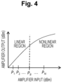
- Fig. 4 illustrates input/output characteristics of the power amplifier included in the wireless transmission device 10 illustrated in Fig. 1 .
- the power amplifier exhibits a linear input/output characteristic in a region where the input power is P B or less, but the characteristic becomes nonlinear in a region where the input power exceeds P B .
- distortion is superimposed on the signal amplified by the power amplifier using the nonlinear region. If the distortion occurs in the received signal, in the wireless reception device 12, the received signal is arranged at a position shifted from the original position on the constellation. As a result, the signal amplified in the nonlinear region is likely to be erroneously recognized as an erroneous symbol in the wireless reception device 12.
- a signal with a large amplitude may enter the nonlinear region of the power amplifier.
- Such a phenomenon is more likely to occur as the PAPR of the multi-level modulation scheme used for communication is larger. Therefore, from the viewpoint of preventing signal misrecognition caused by distortion without distorting the transmission signal, APSK having a low PAPR is superior to QAM having a high PAPR.
- the center column of Fig. 3 represents the above relationship by the indication of QAM " ⁇ (large)" and APSK "o (small)".
- Fig. 5 is a diagram illustrating the suitability of QAM and APSK in comparison between a case where the power amplifier uses a linear region and a case where the power amplifier uses a nonlinear region.
- the problem of distortion does not occur even if any modulation scheme is used.
- a better BER can be obtained by using QAM rather than APSK in relation to the minimum Euclidean distance.
- the center column in Fig. 5 represents the above relationship by the indication of QAM " ⁇ (excellent)" and APSK "o (good)".
- the larger the input power the larger the distortion superimposed on the transmission signal. Therefore, when the input power enters the nonlinear region, a larger distortion is superimposed on the signal corresponding to the peak as the PAPR is higher in the multi-level modulation scheme. Then, as the distortion superimposed on the transmission signal is larger, the signal is more likely to be erroneously recognized in the wireless reception device 12. For this reason, in a situation in which the power transmission device uses the nonlinear region, the communication quality of QAM having a high PAPR is likely to deteriorate more than that of APSK having a low PAPR.
- the rightmost column in Fig. 5 represents the above relationship by the indication of QAM " ⁇ (because of high PAPR)" and APSK " ⁇ (because of low PAPR)".
- the superiority and inferiority of QAM and APSK are reversed depending on whether the operation region of the power amplifier is a linear region or a nonlinear region. Therefore, in the present embodiment, the multi-level modulation scheme used for communication is appropriately switched between QAM and APSK so that excellent communication quality can be obtained in a real environment in response to this reversal.
- Fig. 6 is a block diagram for describing a configuration of the wireless transmission device 10 used in the present embodiment to implement the above functions.
- Each element illustrated in Fig. 6 can be configured by dedicated hardware.
- these elements can also be configured using an arithmetic processing unit and a program for causing the arithmetic processing unit to execute desired processing, in addition to dedicated hardware.
- the wireless transmission device 10 includes an information bit generation unit 14.
- the information bit generation unit 14 generates bit data corresponding to information to be transmitted to the wireless reception device 12.
- the bit data generated by the information bit generation unit 14 is provided to a QAM modulation unit 16 and an APSK modulation unit 18.
- the QAM modulation unit 16 modulates the received bit data according to a QAM scheme.
- the APSK modulation unit 18 modulates the bit data according to an APSK scheme. In either case, the modulated signal is provided to a modulation scheme selection unit 20 and a constellation calculation unit 22.
- the modulation scheme selection unit 20 has a function of determining which one of QAM and APSK is appropriate as a modulation scheme used for communication. When it is determined that QAM is appropriate, the modulated signal generated by the QAM modulation unit 16 is provided to a power amplifier 24. On the other hand, when it is determined that APSK is appropriate, the modulated signal generated by the APSK modulation unit 18 is provided to the power amplifier 24. The process of selecting the modulation scheme by the modulation scheme selection unit 20 will be described in detail later.
- the power amplifier 24 amplifies the modulated signal generated by the QAM modulation unit 16 or the APSK modulation unit 18 to desired transmission power and supplies the transmission power to an antenna 26. As a result, a signal amplified to desired power by the power amplifier 24 is transmitted from the antenna 26 according to the modulation scheme selected by the modulation scheme selection unit 20.
- the wireless transmission device 10 includes an input/output characteristic storage unit 28.
- the input/output characteristic storage unit 28 stores input/output characteristics of the power amplifier 24 in advance. For example, a curve of input/output characteristics as illustrated in Fig. 4 is stored.
- the input/output characteristic storage unit 28 can provide information on the input/output characteristics to the constellation calculation unit 22.
- the constellation calculation unit 22 generates an estimated constellation ⁇ QAM ⁇ corresponding to a QAM-modulated signal on the basis of the QAM-modulated signal acquired from the QAM modulation unit 16, the input/output characteristics acquired from the input/output characteristic storage unit 28, and the transmission power commanded to the power amplifier 24. That is, what kind of distortion is superimposed on each symbol included in the modulated signal can be estimated on the basis of the input/output characteristics of the power amplifier 24 and the transmission power.
- the estimated constellation ⁇ QAM ⁇ is generated by arranging all the symbols included in the QAM-modulated signal on the constellation coordinates.
- the constellation calculation unit 22 similarly generates an estimated constellation ⁇ APSK ⁇ also for an APSK-modulated signal.
- the modulation scheme selection unit 20 acquires the estimated constellation ⁇ QAM ⁇ generated by the constellation calculation unit 22, and calculates an estimated minimum Euclidean distance ⁇ QAM ⁇ for all the symbols included in the estimated constellation. That is, in the estimated constellation ⁇ QAM ⁇ , the straight line distance between the closest symbols is estimated. Similarly, the modulation scheme selection unit 20 calculates an estimated minimum Euclidean distance ⁇ APSK ⁇ on the basis of the estimated constellation ⁇ APSK ⁇ .
- the estimated minimum Euclidean distance ⁇ QAM ⁇ tends to be larger than the estimated minimum Euclidean distance ⁇ APSK ⁇ .
- the relationship is reversed due to the difference in PAPR. In any case, the receiving side can easily recognize the transmission signal correctly as the minimum Euclidean distance is longer.
- the modulation scheme selection unit 20 compares the estimated minimum Euclidean distance ⁇ QAM ⁇ with the estimated minimum Euclidean distance ⁇ APSK ⁇ , and selects the modulation scheme with the longer distance as the scheme to be used for communication. Therefore, according to the wireless transmission device 10 of the present embodiment, it is possible to always employ a modulation scheme advantageous for causing the wireless reception device 12 to correctly recognize a signal regardless of a region in which the power amplifier 24 amplifies the modulated signal.
- Fig. 7 is a flowchart for describing a flow of main processing performed by the wireless transmission device 10 illustrated in Fig. 6 . More specifically, it is a flowchart for describing a flow of processing executed in the modulation scheme selection unit 20 and the constellation calculation unit 22.
- the constellation calculation unit 22 acquires a QAM-modulated signal from the QAM modulation unit 16 (step 102), and acquires an APSK-modulated signal from the APSK modulation unit 18 (step 104). Subsequently, the estimated minimum Euclidean distance ⁇ QAM ⁇ and the estimated minimum Euclidean distance ⁇ APSK ⁇ are calculated (steps 106 and 108).
- the transmission power used for the current transmission and the QAM-modulated signal acquired in step 102 are applied to the input/output characteristics of the power amplifier 24 to generate an estimated constellation ⁇ QAM ⁇ .
- the minimum Euclidean distance in the estimated constellation ⁇ QAM ⁇ is set as the estimated minimum Euclidean distance ⁇ QAM ⁇ .
- the estimated minimum Euclidean distance ⁇ APSK ⁇ is calculated by a similar procedure on the basis of the APSK-modulated signal acquired in step 104.
- step 110 to 114 are executed in the modulation scheme selection unit 20. That is, when the processes of steps 100 to 108 are completed, the modulation scheme selection unit 20 first determines whether or not the estimated minimum Euclidean distance ⁇ APSK ⁇ calculated in step 108 is larger than the estimated minimum Euclidean distance ⁇ QAM ⁇ calculated in step 106 (step 110).
- step 112 when the estimated minimum Euclidean distance ⁇ APSK ⁇ > the estimated minimum Euclidean distance ⁇ QAM ⁇ is recognized, APSK is selected as the modulation scheme used for communication (step 112).
- QAM is selected as the modulation scheme to be used for communication (step 114). Note that the processes of step 102 to 114 are repeatedly executed for each transmission frame.
- the plurality of multi-level modulation schemes can be appropriately switched and used on the basis of the minimum Euclidean distance estimated to be implemented by each transmission signal.
- a modulation scheme advantageous for obtaining high communication quality is always selected. Therefore, according to the wireless communication system of the present embodiment, excellent communication quality can be stably ensured over a wide transmission power range.
- a scheme used for communication is selected on the basis of comparison between the estimated minimum Euclidean distances calculated for each of QAM and APSK.
- the object of comparison may be any object as long as it represents the density of symbols on the estimated constellation.
- one of QAM and APSK may be selected on the basis of comparison of an estimated average Euclidean distance that is an average of inter-symbol distances on the estimated constellation.
- the estimated constellation ⁇ QAM ⁇ corresponding to the QAM-modulated signal and the estimated constellation ⁇ APSK ⁇ corresponding to the APSK-modulated signal are generated, and the estimated minimum Euclidean distances are calculated on the basis of the generated estimated constellations.
- the constellation calculation unit 22 may generate the estimated constellation by reflecting the influence of distortion in the normal constellation for each of QAM and APSK without taking in the QAM and APSK-modulated signals.
- the estimated Euclidean distance ⁇ QAM ⁇ obtained from the estimated constellation ⁇ QAM ⁇ and the estimated Euclidean distance ⁇ APSK ⁇ obtained from the estimated constellation ⁇ APSK ⁇ are directly compared, but the present disclosure is not limited thereto.
- a bias value set according to the communication quality may be added to or subtracted from one of the Euclidean distances.
- a non-optimum modulation scheme is selected according to the situation, but the frequency of switching the modulation scheme can be reduced.
- the estimated constellation is updated for each frame, and an optimum modulation scheme is selected for each frame.
- the present disclosure is not limited thereto. That is, the frequency of switching the modulation scheme may be set lower than that of each frame by updating the estimated constellation every plurality of frames or every fixed time.
- the wireless transmission device 10 does not include an adaptive transmission power control unit (ATPC: adaptive transmission power control), but the present disclosure is not limited thereto. That is, ATPC may be incorporated in the wireless transmission device 10, and the transmission power used by the power amplifier 24 may be designated by the ATPC.
- ATPC adaptive transmission power control unit
Landscapes
- Engineering & Computer Science (AREA)
- Signal Processing (AREA)
- Computer Networks & Wireless Communication (AREA)
- Transmitters (AREA)
Abstract
Description
- The present disclosure relates to a wireless communication method, a wireless communication system, and a wireless transmission device, and more particularly, to a wireless communication method, a wireless communication system, and a wireless transmission device suitable for use in an environment where transmission power changes.
-
Non Patent Literature 1 below describes details of quadrature amplitude modulation (QAM), which is one multi-level modulation scheme for wireless communication. In addition, Non Patent Literature 2 below describes details of amplitude phase shift keying (APSK) which is another example of a multi-level modulation scheme. As represented by these schemes, various multi-level modulation schemes are used in the field of wireless communication. - With regard to the influence of different multi-level modulation schemes on the quality of wireless communication, Non Patent Literature 3 below discloses the following matters:
- 1. Peak to average power ratio (PAPR) is different for each multi-level modulation scheme;
- 2. When a power amplifier on the transmitting side uses a nonlinear region, a signal is more likely to be erroneously recognized on the receiving side as the PAPR is higher;
- 3. When APSK and QAM are compared, the APSK having a lower PAPR is more robust when transmitted in the nonlinear region of the power amplifier.
-
- Non Patent Literature 1: IEEE Std 802.11ac-2013, IEEE, 2013
- Non Patent Literature 2: ETSI EN 302 307-1 V1.4.1, Digital Video Broadcasting, November 2014
- Non Patent Literature 3: "M-APSK Modulation for SC-FDMA Communication Systems", Juraj GAZDA, Denis DUPAK, Dusan KOCUR, Department of Electronics and Multimedia Communications, Faculty of Electrical Engineering and Informatics, Technical University of Kosice, Letna 9, 04200 Kosice, Slovakia, 2011
- On the other hand, in a constellation of symbols used in QAM, a plurality of symbols are arranged in a lattice. On the other hand, in the constellation of symbols used in APSK, a plurality of symbols are arranged in one or more concentric circles. When comparing the two, if the number of symbols is the same, the minimum Euclidean distance between the symbols arranged on a QAM constellation is longer than the minimum Euclidean distance on an APSK constellation.
- In the communication of the multi-level modulation scheme, the receiving side recognizes the received signal as one of the symbols on the constellation stored in advance. Specifically, likelihoods of a received signal and symbols present around the received signal are calculated for the constellation, and a symbol having the highest likelihood is recognized as the received signal. In this case, the identification accuracy of the received signal becomes higher as the Euclidean distance between the symbols arranged on the constellation is longer. Therefore, in an environment where a received signal is transmitted without distortion, QAM having a longer minimum Euclidean distance is more likely to ensure an excellent bit error rate (BER) compared with APSK.
- In a situation where the power amplifier on the transmitting side can amplify a transmission signal in a linear region, distortion hardly occurs in the transmission signal. Therefore, in such a situation, it is easier to ensure better communication quality with QAM than with APSK. On the other hand, in a situation where the transmission power is large and the power amplifier amplifies a signal in a nonlinear region, the case of using APSK is more likely to ensure excellent communication quality than the case of using QAM due to the reason described in Non Patent Literature 3.
- In this way, when the suitability of each multi-level modulation scheme is compared, the superiority and inferiority may be reversed depending on whether the power amplifier uses the linear region or the nonlinear region. However, conventionally, control for appropriately switching a multi-level modulation scheme used for communication according to transmission power has not been studied. In this regard, the conventional wireless communication technology has room for further improvement by switching and using a plurality of multi-level modulation schemes.
- The present disclosure has been made in view of the above problems, and a first object of the present disclosure is to provide a wireless communication method for ensuring excellent communication quality over a wide transmission power range by appropriately switching and using a plurality of multi-level modulation schemes according to transmission power.
- In addition, a second object of the present disclosure is to provide a wireless communication system that ensures excellent communication quality over a wide transmission power range by appropriately switching and using a plurality of multi-level modulation schemes according to transmission power.
- In addition, a third object of the present disclosure is to provide a wireless transmission device that ensures excellent communication quality over a wide transmission power range by appropriately switching and using a plurality of multi-level modulation schemes according to transmission power.
- In order to achieve the above objects, a first aspect is desirably a wireless communication method using a wireless transmission device and a wireless reception device that support at least two multi-level modulation schemes,
- the at least two multi-level modulation schemes including a first modulation scheme and a second modulation scheme, and
- the wireless transmission device including a power amplifier that varies transmission power, the wireless communication method including:
- a step of calculating, by the wireless transmission device, a first estimated constellation predicted to occur when a signal modulated using the first modulation scheme is amplified by the power amplifier at desired transmission power, on the basis of input/output characteristics of the power amplifier;
- a step of calculating, by the wireless transmission device, a second estimated constellation predicted to occur when a signal modulated using the second modulation scheme is amplified by the power amplifier at the desired transmission power, on the basis of the input/output characteristics;
- a step of calculating, by the wireless transmission device, a first estimated Euclidean distance, which is a characteristic value of an inter-symbol distance in the first estimated constellation;
- a step of calculating, by the wireless transmission device, a second estimated Euclidean distance, which is a characteristic value of an inter-symbol distance in the second estimated constellation;
- a step of selecting, by the wireless transmission device, a modulation scheme that generates the smaller one of the first estimated Euclidean distance and the second estimated Euclidean distance as a scheme used for communication;
- a step of commanding, by the wireless transmission device, the wireless reception device to perform communication using the selected modulation scheme; and
- a step of communicating, by the wireless reception device, with the wireless transmission device using the commanded modulation scheme.
- A second aspect is desirably a wireless communication system using a wireless transmission device and a wireless reception device that support at least two multi-level modulation schemes, in which
- the at least two multi-level modulation schemes include a first modulation scheme and a second modulation scheme,
- the wireless transmission device
- includes a power amplifier that varies transmission power, and
- is configured to execute:
- a process of calculating a first estimated constellation predicted to occur when a signal modulated using the first modulation scheme is amplified by the power amplifier at desired transmission power, on the basis of input/output characteristics of the power amplifier;
- a process of calculating a second estimated constellation predicted to occur when a signal modulated using the second modulation scheme is amplified by the power amplifier at the desired transmission power, on the basis of the input/output characteristics;
- a process of calculating a first estimated Euclidean distance, which is a characteristic value of an inter-symbol distance in the first estimated constellation;
- a process of calculating a second estimated Euclidean distance, which is a characteristic value of an inter-symbol distance in the second estimated constellation;
- a process of selecting a modulation scheme that generates the smaller one of the first estimated Euclidean distance and the second estimated Euclidean distance as a scheme used for communication; and
- a process of commanding the wireless reception device to perform communication using the selected modulation scheme, and
- the wireless reception device is configured to communicate with the wireless transmission device using the commanded modulation scheme.
- A third aspect is desirably a wireless transmission device that supports at least two multi-level modulation schemes and has a function of communicating with a wireless reception device that supports the at least two multi-level modulation schemes, in which
- the at least two multi-level modulation schemes include a first modulation scheme and a second modulation scheme,
- the wireless transmission device
- includes a power amplifier that varies transmission power, and
- is configured to execute:
- a process of calculating a first estimated constellation predicted to occur when a signal modulated using the first modulation scheme is amplified by the power amplifier at desired transmission power, on the basis of input/output characteristics of the power amplifier;
- a process of calculating a second estimated constellation predicted to occur when a signal modulated using the second modulation scheme is amplified by the power amplifier at the desired transmission power, on the basis of the input/output characteristics;
- a process of calculating a first estimated Euclidean distance, which is a characteristic value of an inter-symbol distance in the first estimated constellation;
- a process of calculating a second estimated Euclidean distance, which is a characteristic value of an inter-symbol distance in the second estimated constellation;
- a process of selecting a modulation scheme that generates the smaller one of the first estimated Euclidean distance and the second estimated Euclidean distance as a scheme used for communication; and
- a process of commanding the wireless reception device to perform communication using the selected modulation scheme.
- According to the first to third aspects, it is possible to ensure excellent communication quality in a wide transmission power range by appropriately switching a plurality of multi-level modulation schemes according to transmission power in an environment where the plurality of multi-level modulation schemes can be used.
-
-
Fig. 1 is a diagram illustrating a configuration example of a wireless communication system according to a first embodiment of the present disclosure. -
Fig. 2 is a diagram illustrating an APSK constellation and a QAM constellation in comparison. -
Fig. 3 is a diagram illustrating characteristics of QAM and APSK in comparison. -
Fig. 4 is a diagram for describing input/output characteristics of a power amplifier included in a wireless transmission device illustrated inFig. 1 . -
Fig. 5 is a diagram illustrating the suitability of QAM and APSK in comparison between a case where the power amplifier uses a linear region and a case where the power amplifier uses a nonlinear region. -
Fig. 6 is a block diagram for describing a configuration of the wireless transmission device according to the first embodiment of the present disclosure. -
Fig. 7 is a flowchart for describing a flow of main processing performed by the wireless transmission device illustrated inFig. 6 . -
Fig. 1 is a diagram illustrating a configuration example of a wireless communication system according to a first embodiment of the present disclosure. As illustrated inFig. 1 , the system of the present embodiment includes awireless transmission device 10 and awireless reception device 12. Thewireless transmission device 10 can be, for example, a wireless communication base station managed by a communication carrier or an access point of a wireless local area network (LAN). On the other hand, thewireless reception device 12 may be a terminal device capable of performing communication in both or one of the licensed band and the unlicensed band. - In the present embodiment, the
wireless transmission device 10 and thewireless reception device 12 each have a function of supporting a plurality of multi-level modulation schemes. Here, specifically, a case where thewireless transmission device 10 and thewireless reception device 12 support quadrature amplitude modulation (QAM) and amplitude phase shift keying (APSK), respectively, will be described. -
Fig. 2 is a diagram illustrating an APSK constellation and a QAM constellation in comparison. More specifically, the left side ofFig. 2 illustrates a 16 APSK constellation that handles 16 symbols. In addition, the right side ofFig. 2 illustrates a 16 QAM constellation that handles 16 symbols in the same manner. The position of each symbol represents amplitude and phase. - In the 16 APSK constellation, 16 symbols are arranged at equal intervals by eight symbols on two concentric circles. On the other hand, in the 16 QAM constellation, 16 symbols are arranged at equal intervals in a lattice. In the drawing, the minimum Euclidean distance between symbols in each constellation is represented by a bidirectional arrow. When comparing the two, it can be seen that the minimum Euclidean distance in the case of QAM in which symbols are arranged in a lattice is larger than that in the case of APSK.
- Next, a peak to average power ratio (PAPR) will be considered. For transmission of individual symbols on a constellation, a larger amplitude requires a larger power. Therefore, in the APSK, peak power occurs when eight symbols arranged on the outer concentric circle are transmitted. On the other hand, in the case of QAM, peak power occurs when four symbols positioned at four corners are transmitted. Therefore, the ratio of the peak transmission power to the value obtained by averaging the transmission power for all the symbols is lower in the APSK. Therefore, when APSK is used, the PAPR tends to be a lower value than when QAM is used.
-
Fig. 3 illustrates the characteristics of the minimum Euclidean distance and PAPR described above in comparison between QAM and APSK. o and × illustrated in the drawing indicate superiority and inferiority in ensuring a good bit error rate (BER) in wireless communication. The reason why such superiority and inferiority occur will be described below. - The
wireless reception device 12 illustrated inFig. 1 receives a command regarding a modulation scheme to be used for communication from thewireless transmission device 10, and selects a modulation scheme according to the command. In any modulation scheme, thewireless reception device 12 arranges the received signal on a constellation on the basis of the amplitude and the phase, and calculates a likelihood with the received signal for each of the plurality of symbols located around the received signal. Then, the received signal is recognized as a symbol having the highest likelihood. - The longer the minimum Euclidean distance on the constellation is, the large difference is likely to occur in the likelihood calculated for each symbol. Therefore, if the received signal is correctly arranged on the constellation, it is easier to ensure the excellent BER when the QAM having a large minimum Euclidean distance is used than when the APSK having a small minimum Euclidean distance is used. The rightmost column in
Fig. 3 represents the relationship as QAM "o (large)" and APSK "× (small)". -
Fig. 4 illustrates input/output characteristics of the power amplifier included in thewireless transmission device 10 illustrated inFig. 1 . As illustrated inFig. 4 , the power amplifier exhibits a linear input/output characteristic in a region where the input power is PB or less, but the characteristic becomes nonlinear in a region where the input power exceeds PB. Then, distortion is superimposed on the signal amplified by the power amplifier using the nonlinear region. If the distortion occurs in the received signal, in thewireless reception device 12, the received signal is arranged at a position shifted from the original position on the constellation. As a result, the signal amplified in the nonlinear region is likely to be erroneously recognized as an erroneous symbol in thewireless reception device 12. - When the
wireless transmission device 10 transmits a radio signal, even if the average power falls within the linear region, a signal with a large amplitude may enter the nonlinear region of the power amplifier. Such a phenomenon is more likely to occur as the PAPR of the multi-level modulation scheme used for communication is larger. Therefore, from the viewpoint of preventing signal misrecognition caused by distortion without distorting the transmission signal, APSK having a low PAPR is superior to QAM having a high PAPR. The center column ofFig. 3 represents the above relationship by the indication of QAM "× (large)" and APSK "o (small)". -
Fig. 5 is a diagram illustrating the suitability of QAM and APSK in comparison between a case where the power amplifier uses a linear region and a case where the power amplifier uses a nonlinear region. When the input power to the power amplifier falls within the linear region, the problem of distortion does not occur even if any modulation scheme is used. In this case, a better BER can be obtained by using QAM rather than APSK in relation to the minimum Euclidean distance. The center column inFig. 5 represents the above relationship by the indication of QAM "⊙ (excellent)" and APSK "o (good)". - In the nonlinear region of the power amplifier, the larger the input power, the larger the distortion superimposed on the transmission signal. Therefore, when the input power enters the nonlinear region, a larger distortion is superimposed on the signal corresponding to the peak as the PAPR is higher in the multi-level modulation scheme. Then, as the distortion superimposed on the transmission signal is larger, the signal is more likely to be erroneously recognized in the
wireless reception device 12. For this reason, in a situation in which the power transmission device uses the nonlinear region, the communication quality of QAM having a high PAPR is likely to deteriorate more than that of APSK having a low PAPR. The rightmost column inFig. 5 represents the above relationship by the indication of QAM "× (because of high PAPR)" and APSK "Δ (because of low PAPR)". - As described above, the superiority and inferiority of QAM and APSK are reversed depending on whether the operation region of the power amplifier is a linear region or a nonlinear region. Therefore, in the present embodiment, the multi-level modulation scheme used for communication is appropriately switched between QAM and APSK so that excellent communication quality can be obtained in a real environment in response to this reversal.
-
Fig. 6 is a block diagram for describing a configuration of thewireless transmission device 10 used in the present embodiment to implement the above functions. Each element illustrated inFig. 6 can be configured by dedicated hardware. Furthermore, these elements can also be configured using an arithmetic processing unit and a program for causing the arithmetic processing unit to execute desired processing, in addition to dedicated hardware. - As illustrated in
Fig. 6 , thewireless transmission device 10 includes an informationbit generation unit 14. The information bitgeneration unit 14 generates bit data corresponding to information to be transmitted to thewireless reception device 12. The bit data generated by the informationbit generation unit 14 is provided to aQAM modulation unit 16 and anAPSK modulation unit 18. - The
QAM modulation unit 16 modulates the received bit data according to a QAM scheme. On the other hand, theAPSK modulation unit 18 modulates the bit data according to an APSK scheme. In either case, the modulated signal is provided to a modulationscheme selection unit 20 and aconstellation calculation unit 22. - The modulation
scheme selection unit 20 has a function of determining which one of QAM and APSK is appropriate as a modulation scheme used for communication. When it is determined that QAM is appropriate, the modulated signal generated by theQAM modulation unit 16 is provided to apower amplifier 24. On the other hand, when it is determined that APSK is appropriate, the modulated signal generated by theAPSK modulation unit 18 is provided to thepower amplifier 24. The process of selecting the modulation scheme by the modulationscheme selection unit 20 will be described in detail later. - The
power amplifier 24 amplifies the modulated signal generated by theQAM modulation unit 16 or theAPSK modulation unit 18 to desired transmission power and supplies the transmission power to anantenna 26. As a result, a signal amplified to desired power by thepower amplifier 24 is transmitted from theantenna 26 according to the modulation scheme selected by the modulationscheme selection unit 20. - The
wireless transmission device 10 according to the present embodiment includes an input/outputcharacteristic storage unit 28. The input/outputcharacteristic storage unit 28 stores input/output characteristics of thepower amplifier 24 in advance. For example, a curve of input/output characteristics as illustrated inFig. 4 is stored. The input/outputcharacteristic storage unit 28 can provide information on the input/output characteristics to theconstellation calculation unit 22. - The
constellation calculation unit 22 generates an estimated constellation {QAM} corresponding to a QAM-modulated signal on the basis of the QAM-modulated signal acquired from theQAM modulation unit 16, the input/output characteristics acquired from the input/outputcharacteristic storage unit 28, and the transmission power commanded to thepower amplifier 24. That is, what kind of distortion is superimposed on each symbol included in the modulated signal can be estimated on the basis of the input/output characteristics of thepower amplifier 24 and the transmission power. Here, assuming that the distortion is superimposed on each symbol, the estimated constellation {QAM} is generated by arranging all the symbols included in the QAM-modulated signal on the constellation coordinates. Theconstellation calculation unit 22 similarly generates an estimated constellation {APSK} also for an APSK-modulated signal. - The modulation
scheme selection unit 20 acquires the estimated constellation {QAM} generated by theconstellation calculation unit 22, and calculates an estimated minimum Euclidean distance {QAM} for all the symbols included in the estimated constellation. That is, in the estimated constellation {QAM}, the straight line distance between the closest symbols is estimated. Similarly, the modulationscheme selection unit 20 calculates an estimated minimum Euclidean distance {APSK} on the basis of the estimated constellation {APSK}. - When the
power amplifier 24 amplifies the signal in the linear region, since a large distortion is not superimposed on the transmission signal, the estimated minimum Euclidean distance {QAM} tends to be larger than the estimated minimum Euclidean distance {APSK}. On the other hand, in a situation of using the nonlinear region of thepower amplifier 24, the relationship is reversed due to the difference in PAPR. In any case, the receiving side can easily recognize the transmission signal correctly as the minimum Euclidean distance is longer. - In the present embodiment, the modulation
scheme selection unit 20 compares the estimated minimum Euclidean distance {QAM} with the estimated minimum Euclidean distance {APSK}, and selects the modulation scheme with the longer distance as the scheme to be used for communication. Therefore, according to thewireless transmission device 10 of the present embodiment, it is possible to always employ a modulation scheme advantageous for causing thewireless reception device 12 to correctly recognize a signal regardless of a region in which thepower amplifier 24 amplifies the modulated signal. -
Fig. 7 is a flowchart for describing a flow of main processing performed by thewireless transmission device 10 illustrated inFig. 6 . More specifically, it is a flowchart for describing a flow of processing executed in the modulationscheme selection unit 20 and theconstellation calculation unit 22. - In
Fig. 7 , the processes ofsteps 100 to 108 are executed in theconstellation calculation unit 22. Specifically, first, input/output characteristics of thepower amplifier 24 are read from the input/output characteristic storage unit 28 (step 100). The process ofstep 100, that is, the process surrounded by a broken-line frame inFig. 7 may be performed only once as an initialization process at the start of the operation of thewireless transmission device 10. - Next, the
constellation calculation unit 22 acquires a QAM-modulated signal from the QAM modulation unit 16 (step 102), and acquires an APSK-modulated signal from the APSK modulation unit 18 (step 104). Subsequently, the estimated minimum Euclidean distance {QAM} and the estimated minimum Euclidean distance {APSK} are calculated (steps 106 and 108). - In the calculation of the estimated minimum Euclidean distance {QAM}, first, the transmission power used for the current transmission and the QAM-modulated signal acquired in
step 102 are applied to the input/output characteristics of thepower amplifier 24 to generate an estimated constellation {QAM}. Then, the minimum Euclidean distance in the estimated constellation {QAM} is set as the estimated minimum Euclidean distance {QAM}. The estimated minimum Euclidean distance {APSK} is calculated by a similar procedure on the basis of the APSK-modulated signal acquired instep 104. - The processes of
step 110 to 114 are executed in the modulationscheme selection unit 20. That is, when the processes ofsteps 100 to 108 are completed, the modulationscheme selection unit 20 first determines whether or not the estimated minimum Euclidean distance {APSK} calculated instep 108 is larger than the estimated minimum Euclidean distance {QAM} calculated in step 106 (step 110). - Then, when the estimated minimum Euclidean distance {APSK} > the estimated minimum Euclidean distance {QAM} is recognized, APSK is selected as the modulation scheme used for communication (step 112). On the other hand, when the above relationship is not recognized, QAM is selected as the modulation scheme to be used for communication (step 114). Note that the processes of
step 102 to 114 are repeatedly executed for each transmission frame. - As described above, according to the wireless communication system of the present embodiment, the plurality of multi-level modulation schemes can be appropriately switched and used on the basis of the minimum Euclidean distance estimated to be implemented by each transmission signal. As a result, even when the
power amplifier 24 uses any transmission power, a modulation scheme advantageous for obtaining high communication quality is always selected. Therefore, according to the wireless communication system of the present embodiment, excellent communication quality can be stably ensured over a wide transmission power range. - Incidentally, in the first embodiment described above, two of 16 QAM and 16 APSK are used as the multi-level modulation scheme, but the present disclosure is not limited thereto. The number of symbols is not limited to 16, and the number of symbols of the two modulation schemes may be different. In addition, various transmission schemes such as orthogonal frequency division multiplexing (OFDM) transmission, discrete Fourier transform-spread-OFDM (DFT-s-OFDM) transmission, and single carrier (SC) transmission can be applied. Various system configurations such as a single input and single output (SISO) configuration and a multiple input and multiple output (MIMO) configuration can be applied. Further, schemes such as Faster-than-Nyquist (FTN) transmission and Nyquist transmission can also be applied. In addition, three or more modulation schemes may be used to appropriately select an optimum modulation scheme from among these modulation schemes.
- In addition, in the first embodiment described above, a scheme used for communication is selected on the basis of comparison between the estimated minimum Euclidean distances calculated for each of QAM and APSK. However, the present disclosure is not limited thereto. The object of comparison may be any object as long as it represents the density of symbols on the estimated constellation. For example, one of QAM and APSK may be selected on the basis of comparison of an estimated average Euclidean distance that is an average of inter-symbol distances on the estimated constellation.
- In the first embodiment, the estimated constellation {QAM} corresponding to the QAM-modulated signal and the estimated constellation {APSK} corresponding to the APSK-modulated signal are generated, and the estimated minimum Euclidean distances are calculated on the basis of the generated estimated constellations. However, the present disclosure is not limited thereto. For example, the
constellation calculation unit 22 may generate the estimated constellation by reflecting the influence of distortion in the normal constellation for each of QAM and APSK without taking in the QAM and APSK-modulated signals. - Furthermore, in the first embodiment described above, the estimated Euclidean distance {QAM} obtained from the estimated constellation {QAM} and the estimated Euclidean distance {APSK} obtained from the estimated constellation {APSK} are directly compared, but the present disclosure is not limited thereto. For example, a bias value set according to the communication quality may be added to or subtracted from one of the Euclidean distances. In this case, a non-optimum modulation scheme is selected according to the situation, but the frequency of switching the modulation scheme can be reduced.
- Furthermore, in the first embodiment described above, the estimated constellation is updated for each frame, and an optimum modulation scheme is selected for each frame. However, the present disclosure is not limited thereto. That is, the frequency of switching the modulation scheme may be set lower than that of each frame by updating the estimated constellation every plurality of frames or every fixed time.
- In addition, in the first embodiment described above, the
wireless transmission device 10 does not include an adaptive transmission power control unit (ATPC: adaptive transmission power control), but the present disclosure is not limited thereto. That is, ATPC may be incorporated in thewireless transmission device 10, and the transmission power used by thepower amplifier 24 may be designated by the ATPC. -
- 10
- Wireless transmission device
- 12
- Wireless reception device
- 16
- QAM modulation unit
- 18
- APSK modulation unit
- 20
- Modulation scheme selection unit
- 22
- Constellation calculation unit
- 24
- Power amplifier
- 28
- Input/output characteristic storage unit
Claims (8)
- A wireless communication method using a wireless transmission device and a wireless reception device that support at least two multi-level modulation schemes,the at least two multi-level modulation schemes including a first modulation scheme and a second modulation scheme, andthe wireless transmission device including a power amplifier that varies transmission power, the wireless communication method comprising:a step of calculating, by the wireless transmission device, a first estimated constellation predicted to occur when a signal modulated using the first modulation scheme is amplified by the power amplifier at desired transmission power, on the basis of input/output characteristics of the power amplifier;a step of calculating, by the wireless transmission device, a second estimated constellation predicted to occur when a signal modulated using the second modulation scheme is amplified by the power amplifier at the desired transmission power, on the basis of the input/output characteristics;a step of calculating, by the wireless transmission device, a first estimated Euclidean distance, which is a characteristic value of an inter-symbol distance in the first estimated constellation;a step of calculating, by the wireless transmission device, a second estimated Euclidean distance, which is a characteristic value of an inter-symbol distance in the second estimated constellation;a step of selecting, by the wireless transmission device, a modulation scheme that generates the smaller one of the first estimated Euclidean distance and the second estimated Euclidean distance as a scheme used for communication;a step of commanding, by the wireless transmission device, the wireless reception device to perform communication using the selected modulation scheme; anda step of communicating, by the wireless reception device, with the wireless transmission device using the commanded modulation scheme.
- The wireless communication method according to claim 1, further comprising:a step of modulating, by the wireless transmission device, information bits to be transmitted to the wireless reception device using the first modulation scheme to generate a first modulated signal; anda step of modulating, by the wireless transmission device, the information bits using the second modulation scheme to generate a second modulated signal, whereinthe first estimated constellation is formed by a set of symbols generated when the first modulated signal is amplified by the power amplifier at the desired transmission power, andthe second estimated constellation is formed by a set of symbols generated when the second modulated signal is amplified by the power amplifier at the desired transmission power.
- The wireless communication method according to claim 1, whereinthe first estimated constellation is formed by a set of symbols generated when all symbols included in a normal constellation of the first modulation scheme are amplified by the power amplifier at the desired transmission power, andthe second estimated constellation is formed by a set of symbols generated when all symbols included in a normal constellation of the second modulation scheme are amplified by the power amplifier at the desired transmission power.
- The wireless communication method according to any one of claims 1 to 3, whereinthe first estimated Euclidean distance is an estimated minimum Euclidean distance in the first estimated constellation, andthe second estimated Euclidean distance is an estimated minimum Euclidean distance in the second estimated constellation.
- The wireless communication method according to any one of claims 1 to 3, whereinthe first estimated Euclidean distance is an estimated average Euclidean distance in the first estimated constellation, andthe second estimated Euclidean distance is an estimated average Euclidean distance in the second estimated constellation.
- The wireless communication method according to any one of claims 1 to 5, further comprising:a step of setting, by the wireless transmission device, a bias value on the basis of required communication quality; anda step of applying, by the wireless transmission device, addition or subtraction processing of the bias value to the first estimated Euclidean distance or the second estimated Euclidean distance.
- A wireless communication system using a wireless transmission device and a wireless reception device that support at least two multi-level modulation schemes, whereinthe at least two multi-level modulation schemes include a first modulation scheme and a second modulation scheme,the wireless transmission deviceincludes a power amplifier that varies transmission power, andis configured to execute:a process of calculating a first estimated constellation predicted to occur when a signal modulated using the first modulation scheme is amplified by the power amplifier at desired transmission power, on the basis of input/output characteristics of the power amplifier;a process of calculating a second estimated constellation predicted to occur when a signal modulated using the second modulation scheme is amplified by the power amplifier at the desired transmission power, on the basis of the input/output characteristics;a process of calculating a first estimated Euclidean distance, which is a characteristic value of an inter-symbol distance in the first estimated constellation;a process of calculating a second estimated Euclidean distance, which is a characteristic value of an inter-symbol distance in the second estimated constellation;a process of selecting a modulation scheme that generates the smaller one of the first estimated Euclidean distance and the second estimated Euclidean distance as a scheme used for communication; anda process of commanding the wireless reception device to perform communication using the selected modulation scheme, andthe wireless reception device is configured to communicate with the wireless transmission device using the commanded modulation scheme.
- A wireless transmission device that supports at least two multi-level modulation schemes and has a function of communicating with a wireless reception device that supports the at least two multi-level modulation schemes, whereinthe at least two multi-level modulation schemes include a first modulation scheme and a second modulation scheme,the wireless transmission devicecomprises a power amplifier that varies transmission power, andis configured to execute:a process of calculating a first estimated constellation predicted to occur when a signal modulated using the first modulation scheme is amplified by the power amplifier at desired transmission power, on the basis of input/output characteristics of the power amplifier;a process of calculating a second estimated constellation predicted to occur when a signal modulated using the second modulation scheme is amplified by the power amplifier at the desired transmission power, on the basis of the input/output characteristics;a process of calculating a first estimated Euclidean distance, which is a characteristic value of an inter-symbol distance in the first estimated constellation;a process of calculating a second estimated Euclidean distance, which is a characteristic value of an inter-symbol distance in the second estimated constellation;a process of selecting a modulation scheme that generates the smaller one of the first estimated Euclidean distance and the second estimated Euclidean distance as a scheme used for communication; anda process of commanding the wireless reception device to perform communication using the selected modulation scheme.
Applications Claiming Priority (1)
| Application Number | Priority Date | Filing Date | Title |
|---|---|---|---|
| PCT/JP2022/004605 WO2023148954A1 (en) | 2022-02-07 | 2022-02-07 | Radio communication method, radio communication system, and radio transmission device |
Publications (2)
| Publication Number | Publication Date |
|---|---|
| EP4478670A1 true EP4478670A1 (en) | 2024-12-18 |
| EP4478670A4 EP4478670A4 (en) | 2025-12-17 |
Family
ID=87553267
Family Applications (1)
| Application Number | Title | Priority Date | Filing Date |
|---|---|---|---|
| EP22924864.6A Pending EP4478670A4 (en) | 2022-02-07 | 2022-02-07 | RADIO COMMUNICATION METHOD, RADIO COMMUNICATION SYSTEM, AND RADIO COMMUNICATION DEVICE |
Country Status (4)
| Country | Link |
|---|---|
| US (1) | US12457146B2 (en) |
| EP (1) | EP4478670A4 (en) |
| JP (1) | JP7658469B2 (en) |
| WO (1) | WO2023148954A1 (en) |
Families Citing this family (1)
| Publication number | Priority date | Publication date | Assignee | Title |
|---|---|---|---|---|
| WO2025253626A1 (en) * | 2024-06-07 | 2025-12-11 | Ntt株式会社 | Wireless communication system and transmission device |
Family Cites Families (11)
| Publication number | Priority date | Publication date | Assignee | Title |
|---|---|---|---|---|
| JP3464656B2 (en) | 2000-11-06 | 2003-11-10 | 松下電器産業株式会社 | Wireless communication device |
| JP4460412B2 (en) * | 2003-11-26 | 2010-05-12 | パナソニック株式会社 | Reception device and partial bit determination method |
| JP4478119B2 (en) * | 2005-05-25 | 2010-06-09 | パナソニック株式会社 | Receiver |
| JP2007089052A (en) * | 2005-09-26 | 2007-04-05 | Murata Mfg Co Ltd | Communication system |
| JP4720468B2 (en) * | 2005-12-07 | 2011-07-13 | 日本電気株式会社 | Nonlinear distortion compensation circuit and method, and wireless transmission system using the same |
| RU2397616C1 (en) | 2006-05-26 | 2010-08-20 | Нек Корпорейшн | Radio communication device, radio communication system and radio communication method |
| JP2011009946A (en) * | 2009-06-24 | 2011-01-13 | Sharp Corp | Communication system, communication equipment, communication method, and communication program |
| US9780990B2 (en) * | 2014-10-31 | 2017-10-03 | Tyco Electronics Subsea Communications Llc | System and method for multi-dimensional modulation using multiple constellations |
| US9716536B2 (en) * | 2015-03-19 | 2017-07-25 | Mitsubishi Electric Research Laboratories, Inc. | System and method for wireless communications over fading channels |
| US9553754B1 (en) * | 2015-09-10 | 2017-01-24 | Qualcomm Incorporated | Post distortion in satellite communications |
| US11700081B1 (en) * | 2022-02-01 | 2023-07-11 | Qualcomm Incorporated | Channel aware set partitioning for multi-level coding |
-
2022
- 2022-02-07 US US18/833,070 patent/US12457146B2/en active Active
- 2022-02-07 JP JP2023578327A patent/JP7658469B2/en active Active
- 2022-02-07 EP EP22924864.6A patent/EP4478670A4/en active Pending
- 2022-02-07 WO PCT/JP2022/004605 patent/WO2023148954A1/en not_active Ceased
Also Published As
| Publication number | Publication date |
|---|---|
| US12457146B2 (en) | 2025-10-28 |
| JPWO2023148954A1 (en) | 2023-08-10 |
| EP4478670A4 (en) | 2025-12-17 |
| JP7658469B2 (en) | 2025-04-08 |
| WO2023148954A1 (en) | 2023-08-10 |
| US20250112814A1 (en) | 2025-04-03 |
Similar Documents
| Publication | Publication Date | Title |
|---|---|---|
| US8532239B2 (en) | Method for error compensation in an OFDM system with diversity | |
| US7313750B1 (en) | Efficient soft decision demapper to minimize viterbi decoder complexity | |
| CN1993953B (en) | Wireless transmission device and wireless transmission method | |
| US6985538B2 (en) | Digital radio communication system and method | |
| US20090046811A1 (en) | Transmitting apparatus, receiving apparatus, transmission method, and reception method | |
| US8879582B2 (en) | Transmitter and transmission method | |
| US20110044407A1 (en) | Adaptive qrd-m algorithm based signal detecting method by using constellation set grouping in spatial multiplexing multiple-input multiple-output system | |
| US8761316B2 (en) | Systems and methods for approximating log likelihood ratios in a communication system | |
| CN101529846A (en) | QAM receiver | |
| US12457146B2 (en) | Wireless communication method, wireless communication system, and wireless transmission device | |
| EP4398533B1 (en) | Wireless communication system, wireless communication method, and wireless communication transmission device | |
| EP4478674A1 (en) | Wireless communication method, wireless communication system, and wireless transmission device | |
| EP4478673A1 (en) | Wireless communication method, wireless communication system, and wireless transmission device | |
| US8194799B2 (en) | Cyclic prefix-based enhanced data recovery method | |
| US20090074101A1 (en) | Detection Performance in Communication Systems | |
| US20250158857A1 (en) | Wireless communication method, wireless communication system, and transmission device | |
| US20250141726A1 (en) | Wireless communication method, wireless communication system, and transmission device | |
| US20250112808A1 (en) | Wireless communication method, wireless communication system, and transmission device | |
| US8019005B2 (en) | Data communication system, data decoding apparatus and method therefor | |
| JP7601239B2 (en) | Wireless communication system, wireless communication method, centralized control device, and wireless communication program | |
| KR100914316B1 (en) | Method for deciding position of mapping symbols, and apparatus and method for modulating binary signal | |
| JP2005341405A (en) | Communication method and wireless device using communication method | |
| CN115706692A (en) | Data transmission method, device, communication node and storage medium | |
| CN114124294A (en) | Adaptive modulation coding method, base station and storage medium | |
| JP2025533040A (en) | Signal modulation method, communication device, and storage medium |
Legal Events
| Date | Code | Title | Description |
|---|---|---|---|
| STAA | Information on the status of an ep patent application or granted ep patent |
Free format text: STATUS: THE INTERNATIONAL PUBLICATION HAS BEEN MADE |
|
| PUAI | Public reference made under article 153(3) epc to a published international application that has entered the european phase |
Free format text: ORIGINAL CODE: 0009012 |
|
| STAA | Information on the status of an ep patent application or granted ep patent |
Free format text: STATUS: REQUEST FOR EXAMINATION WAS MADE |
|
| 17P | Request for examination filed |
Effective date: 20240805 |
|
| AK | Designated contracting states |
Kind code of ref document: A1 Designated state(s): AL AT BE BG CH CY CZ DE DK EE ES FI FR GB GR HR HU IE IS IT LI LT LU LV MC MK MT NL NO PL PT RO RS SE SI SK SM TR |
|
| DAV | Request for validation of the european patent (deleted) | ||
| DAX | Request for extension of the european patent (deleted) | ||
| RAP3 | Party data changed (applicant data changed or rights of an application transferred) |
Owner name: NTT, INC. |
|
| A4 | Supplementary search report drawn up and despatched |
Effective date: 20251117 |
|
| RIC1 | Information provided on ipc code assigned before grant |
Ipc: H04L 27/00 20060101AFI20251111BHEP Ipc: H04L 27/34 20060101ALI20251111BHEP |
|
| GRAP | Despatch of communication of intention to grant a patent |
Free format text: ORIGINAL CODE: EPIDOSNIGR1 |
|
| STAA | Information on the status of an ep patent application or granted ep patent |
Free format text: STATUS: GRANT OF PATENT IS INTENDED |