EP4478569A1 - Apparatus and islanding determination method for grid disturbance - Google Patents
Apparatus and islanding determination method for grid disturbance Download PDFInfo
- Publication number
- EP4478569A1 EP4478569A1 EP24164433.5A EP24164433A EP4478569A1 EP 4478569 A1 EP4478569 A1 EP 4478569A1 EP 24164433 A EP24164433 A EP 24164433A EP 4478569 A1 EP4478569 A1 EP 4478569A1
- Authority
- EP
- European Patent Office
- Prior art keywords
- reactive power
- frequency
- voltage
- inj
- power
- Prior art date
- Legal status (The legal status is an assumption and is not a legal conclusion. Google has not performed a legal analysis and makes no representation as to the accuracy of the status listed.)
- Granted
Links
Images


Classifications
-
- H—ELECTRICITY
- H02—GENERATION; CONVERSION OR DISTRIBUTION OF ELECTRIC POWER
- H02J—ELECTRIC POWER NETWORKS; CIRCUIT ARRANGEMENTS OR SYSTEMS FOR SUPPLYING OR DISTRIBUTING ELECTRIC POWER; SYSTEMS FOR STORING ELECTRIC ENERGY
- H02J3/00—Circuit arrangements for AC mains or AC distribution networks
- H02J3/38—Arrangements for feeding a single network from two or more generators or sources in parallel; Arrangements for feeding already energised networks from additional generators or sources in parallel
- H02J3/388—Arrangements for the handling of islanding, e.g. for disconnection or for avoiding the disconnection of power
-
- G—PHYSICS
- G01—MEASURING; TESTING
- G01R—MEASURING ELECTRIC VARIABLES; MEASURING MAGNETIC VARIABLES
- G01R19/00—Arrangements for measuring currents or voltages or for indicating presence or sign thereof
- G01R19/02—Measuring effective values, i.e. root-mean-square values
-
- G—PHYSICS
- G01—MEASURING; TESTING
- G01R—MEASURING ELECTRIC VARIABLES; MEASURING MAGNETIC VARIABLES
- G01R23/00—Arrangements for measuring frequencies; Arrangements for analysing frequency spectra
- G01R23/02—Arrangements for measuring frequency, e.g. pulse repetition rate; Arrangements for measuring period of current or voltage
- G01R23/04—Arrangements for measuring frequency, e.g. pulse repetition rate; Arrangements for measuring period of current or voltage adapted for measuring in circuits having distributed constants
-
- H—ELECTRICITY
- H02—GENERATION; CONVERSION OR DISTRIBUTION OF ELECTRIC POWER
- H02J—ELECTRIC POWER NETWORKS; CIRCUIT ARRANGEMENTS OR SYSTEMS FOR SUPPLYING OR DISTRIBUTING ELECTRIC POWER; SYSTEMS FOR STORING ELECTRIC ENERGY
- H02J3/00—Circuit arrangements for AC mains or AC distribution networks
- H02J3/001—Arrangements for handling faults or abnormalities, e.g. emergencies or contingencies
- H02J3/0012—Arrangements for handling faults or abnormalities, e.g. emergencies or contingencies characterised by the contingency detection means in AC networks, e.g. using phasor measurement units [PMU], synchrophasors or contingency analysis
-
- H—ELECTRICITY
- H02—GENERATION; CONVERSION OR DISTRIBUTION OF ELECTRIC POWER
- H02J—ELECTRIC POWER NETWORKS; CIRCUIT ARRANGEMENTS OR SYSTEMS FOR SUPPLYING OR DISTRIBUTING ELECTRIC POWER; SYSTEMS FOR STORING ELECTRIC ENERGY
- H02J3/00—Circuit arrangements for AC mains or AC distribution networks
- H02J3/38—Arrangements for feeding a single network from two or more generators or sources in parallel; Arrangements for feeding already energised networks from additional generators or sources in parallel
- H02J3/381—Dispersed generators
-
- H—ELECTRICITY
- H02—GENERATION; CONVERSION OR DISTRIBUTION OF ELECTRIC POWER
- H02J—ELECTRIC POWER NETWORKS; CIRCUIT ARRANGEMENTS OR SYSTEMS FOR SUPPLYING OR DISTRIBUTING ELECTRIC POWER; SYSTEMS FOR STORING ELECTRIC ENERGY
- H02J3/00—Circuit arrangements for AC mains or AC distribution networks
- H02J3/38—Arrangements for feeding a single network from two or more generators or sources in parallel; Arrangements for feeding already energised networks from additional generators or sources in parallel
- H02J3/46—Controlling the sharing of generated power between the generators, sources or networks
- H02J3/50—Controlling the sharing of reactive power
-
- H—ELECTRICITY
- H02—GENERATION; CONVERSION OR DISTRIBUTION OF ELECTRIC POWER
- H02J—ELECTRIC POWER NETWORKS; CIRCUIT ARRANGEMENTS OR SYSTEMS FOR SUPPLYING OR DISTRIBUTING ELECTRIC POWER; SYSTEMS FOR STORING ELECTRIC ENERGY
- H02J3/00—Circuit arrangements for AC mains or AC distribution networks
- H02J3/18—Arrangements for adjusting, eliminating or compensating reactive power in networks
-
- Y—GENERAL TAGGING OF NEW TECHNOLOGICAL DEVELOPMENTS; GENERAL TAGGING OF CROSS-SECTIONAL TECHNOLOGIES SPANNING OVER SEVERAL SECTIONS OF THE IPC; TECHNICAL SUBJECTS COVERED BY FORMER USPC CROSS-REFERENCE ART COLLECTIONS [XRACs] AND DIGESTS
- Y04—INFORMATION OR COMMUNICATION TECHNOLOGIES HAVING AN IMPACT ON OTHER TECHNOLOGY AREAS
- Y04S—SYSTEMS INTEGRATING TECHNOLOGIES RELATED TO POWER NETWORK OPERATION, COMMUNICATION OR INFORMATION TECHNOLOGIES FOR IMPROVING THE ELECTRICAL POWER GENERATION, TRANSMISSION, DISTRIBUTION, MANAGEMENT OR USAGE, i.e. SMART GRIDS
- Y04S10/00—Systems supporting electrical power generation, transmission or distribution
- Y04S10/12—Monitoring or controlling equipment for energy generation units, e.g. distributed energy generation [DER] or load-side generation
-
- Y—GENERAL TAGGING OF NEW TECHNOLOGICAL DEVELOPMENTS; GENERAL TAGGING OF CROSS-SECTIONAL TECHNOLOGIES SPANNING OVER SEVERAL SECTIONS OF THE IPC; TECHNICAL SUBJECTS COVERED BY FORMER USPC CROSS-REFERENCE ART COLLECTIONS [XRACs] AND DIGESTS
- Y04—INFORMATION OR COMMUNICATION TECHNOLOGIES HAVING AN IMPACT ON OTHER TECHNOLOGY AREAS
- Y04S—SYSTEMS INTEGRATING TECHNOLOGIES RELATED TO POWER NETWORK OPERATION, COMMUNICATION OR INFORMATION TECHNOLOGIES FOR IMPROVING THE ELECTRICAL POWER GENERATION, TRANSMISSION, DISTRIBUTION, MANAGEMENT OR USAGE, i.e. SMART GRIDS
- Y04S10/00—Systems supporting electrical power generation, transmission or distribution
- Y04S10/30—State monitoring, e.g. fault, temperature monitoring, insulator monitoring, corona discharge
Definitions
- the disclosure relates to an islanding determination method in a disturbance and distortion system, and more specifically, to an islanding determination method that does not cause false detection even in a section where harmonics exist in the system.
- a passive or active method is used to detect the islanding of distributed power.
- the passive method measures voltage, current, and frequency in a system where distributed power are connected and determines whether or not distributed power is operated in islanding mode based on whether or not the power system is separated.
- the passive method is simple to implement and has excellent speed, there is a non-detection zone (NDZ) in which islanding cannot be determined when a change in values measured when disconnecting the system is small, and it is susceptible to sudden load changes in normal operation. Also, there is a disadvantage in that detection performance is poor when multiple distributed powers are applied.
- NDZ non-detection zone
- minute disturbance elements e.g., reactive power
- changes in voltage/current or frequency due to this disturbance signal are detected, and whether distributed power is operated in islanding mode is determined based on whether or not the power system is separated.
- This conventional active method has the problem of lacking an equation and detailed determination logic for calculating an injection amount of reactive power, and in a system where disturbance and distortion exist, there is problems such as false detection of islanding.
- the disclosure has been created to solve the problems described above, and an object of the disclosure is to provide a method for determining islanding in a disturbance and distortion system comprising a specific equation and determination process for injecting reactive power as an islanding determination method, and providing an islanding determination method in a disturbance and distortion system that does not cause false detection even in sections where disturbances and distortions, i.e., harmonics, exist in the system.
- a method for determining islanding of a system in which a grid and distributed power supply power to a load includes the steps of: a) calculating an amount of reactive power injection based on an active power command and reactive power command received from an upper controller of the distributed power, and setting a failure confirmation count to 0; b) injecting reactive power during a preset cycle among predetermined cycles of an AC voltage that is an output of the distributed power according to the failure confirmation count; c) measuring a frequency and angular frequency of the AC voltage, which is performed simultaneously with the step b); d), after the step b) is completed, increasing the failure confirmation count if a determination criteria based on the frequency and angular frequency measured in the step c) is satisfied; and e), after the step d) is performed, determining an islanding failure when the failure confirmation count reaches a preset value, wherein the step b), the step c), the step d), and the step e) are repeatedly performed until the islanding failure is confirmed
- the step a) may include the steps of: a-1) receiving the active power command and reactive power command from the upper controller, measuring an instantaneous value of the AC voltage at a connection point between the grid and the distributed power using a voltage measurement circuit included in the distributed power, and calculating an effective value and frequency of the AC voltage using the instantaneous value; a-2) calculating a resistance value of the load using active power output from the distributed power; a-3) calculating an inductor value and capacitor value of the load using a preset power quality coefficient; and a-4) determining the amount of the reactive power injection using the effective value of the AC voltage, the inductor value, the capacitor value, and a magnitude of injection frequency.
- the effective value and frequency of the AC voltage may be repeatedly calculated at regular cycles using the instantaneous value.
- the reactive power may be injected during m cycles among n cycles of the AC voltage, and as the failure confirmation count increases, the m and the n may be changed so that a value obtained by dividing the m by the n increases.
- the reactive power when the failure confirmation count is 0, the reactive power may be injected for 3 cycles out of 8 cycles of the AC voltage, when the failure confirmation count is 1, the reactive power may be injected for 3 cycles out of 5 cycles of the AC voltage, and when the failure confirmation count is 2, the reactive power may be injected during 4 cycles out of 5 cycles of the AC voltage.
- the step e) may include confirming the islanding failure when the failure confirmation count is 3.
- the reactive power may be alternately injected in plus and minus directions.
- the angular frequency may be measured by measuring an output of PLL included in the distributed power.
- the reactive power may be injected during a first section in which the reactive power linearly increases, a second section in which the reactive power is maintained, and a third section in which the reactive power linearly decreases, and in the step c), when the failure confirmation count is 0 or 1, the frequency may be measured at three time points in the second section, and the angular frequency may be measured at first and last time points among the three time points.
- the failure confirmation count may be increased using an equation below: ⁇ 1 ⁇ ⁇ 3 ⁇ 2 ⁇ ⁇ f inj f 1 ⁇ f 2 ⁇ f 3 ⁇ f 1 > f 2 > f 3
- ⁇ 1 is the angular frequency measured at the first time point of the three time points
- ⁇ 3 is the angular frequency measured at the last time point among the three time points
- f 1 , f 2 , f 3 are the frequencies measured sequentially at the three time points
- ⁇ f inj is an increment of the injection frequency.
- the reactive power may be injected during a first section in which the reactive power linearly increases, a second section in which the reactive power is maintained, and a third section in which the reactive power linearly decreases
- the frequency when the failure confirmation count is 2, the frequency may be measured at four time points in the second section, and the angular frequency may be measured at first and last time points of the four time points, using an equation below: ⁇ 1 ⁇ ⁇ 4 ⁇ 2 ⁇ ⁇ f inj f 1 ⁇ f 2 ⁇ f 3 ⁇ f 4 ⁇ f 1 > f 2 > f 3 > f 4 f 1 ⁇ f 4 ⁇ ⁇ f inj
- ⁇ 1 is the angular frequency measured at the first time point of the four time points
- ⁇ 4 is the angular frequency measured at the last time point among the four time points
- f 1 , f 2 , f 3 , f 4 are the frequencies measured sequentially at the four time points
- ⁇ 1 is the angular frequency
- an apparatus for determining islanding of a system in which a grid and distributed power supply power to a load includes: a processor configured to: calculate an amount of reactive power injection based on an active power command and reactive power command received from an upper controller of the distributed power; set a failure confirmation count to 0; control injection of reactive power during a preset cycle among predetermined cycles of an AC voltage that is an output of the distributed power according to the failure confirmation count; measure a frequency and angular frequency of the AC voltage, which is performed simultaneously with the injection of reactive power; and after the injection of reactive power is completed, increase the failure confirmation count if a determination criteria based on the measurement of the frequency and the angular frequency of the AC voltage; after increase of the failure confirmation count is performed, determine an islanding failure when the failure confirmation count reaches a preset value, wherein the injection of the reactive power, the measurement of the frequency and the angular frequency of the AC voltage, and increase of the failure confirmation count are repeatedly performed until the islanding failure is confirmed.
- the processor may be further configured to: receive the active power command and reactive power command from the upper controller, measuring an instantaneous value of the AC voltage at a connection point between the grid and the distributed power using a voltage measurement circuit included in the distributed power, and calculating an effective value and frequency of the AC voltage using the instantaneous value; calculate a resistance value of the load using active power output from the distributed power; calculate an inductor value and capacitor value of the load using a preset power quality coefficient; and determine the amount of the reactive power injection using the effective value of the AC voltage, the inductor value, the capacitor value, and a magnitude of injection frequency.
- the processor may be further configured to: inject the reactive power during m cycles among n cycles of the AC voltage; and as the failure confirmation count increases, change the m and the n so that a value obtained by dividing the m by the n increases.
- the processor may be further configured to: measure the angular frequency by measuring an output of PLL included in the distributed power.
- first or second may be used to describe various components but the components are not limited by the above terminologies.
- the above terminologies are used to distinguish one component from the other component, for example, a first component may be referred to as a second component without departing from a scope in accordance with the concept of the disclosure and similarly, a second component may be referred to as a first component.
- a first component may be referred to as a second component without departing from a scope in accordance with the concept of the disclosure and similarly, a second component may be referred to as a first component.
- the element may be directly coupled or directly connected to the other element or coupled or connected to the other element through a third element.
- another element does not intervene therebetween.
- the disclosure relates to a method for detecting an islanding of a distributed power in a power system in which a grid and distributed power supply power to loads.
- the distributed power may be various types of renewable energy generation devices or on board charger (OBC) of electric vehicles operating in vehicle to grid (V2G).
- OBC on board charger
- FIG. 1 is a diagram schematically illustrating a power system to which an islanding determination method is applied in a disturbance and distortion system according to an embodiment of the disclosure.
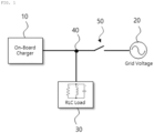
- an OBC 10 and a grid 20 may supply power to a load 30, and the load 30 may be connected to a point common coupling (PCC) 40 located between the OBC 10 and the grid 20, and a recloser 50 may be located between the PCC 40 and the grid 20.
- PCC point common coupling
- FIG. 2 is a block diagram of active power and reactive power control in an islanding determination method in a disturbance and distortion system according to an embodiment of the disclosure.
- an AC current command calculation logic uses the active power and reactive power commands received from an upper controller outside a charger and the reactive power, which is an output value of an islanding prevention logic that performs the algorithm of the disclosure, to calculate an AC current command.
- a PFC inverter current controller calculates a PFC inverter voltage command to control the current according to the calculated current command and sends a switching signal by a PWM output logic.
- the block diagram illustrated in FIG. 2 may be controlled by a controller that controls the OBC 10.
- the controller may be implemented with various devices included in the OBC 10, for example, an electronic device or an apparatus including an electronic device, which may receive measured values or signals from a device such as the PLL illustrated in FIG. 2 and control the OBC 10 based on the received signals.
- the OBC 10 when the OBC 10 operates in V2G mode, after receiving the active power command P target and reactive power command Q target received from the upper controller of an electric vehicle, reactive power is injected according to the received P target and Q target . It is determined whether to operate islanding based on the frequency change rate, angular frequency change amount, and frequency change amount according to the injected reactive power.
- the method includes steps a) to e) sequentially performed by the above-described controller.
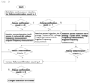
- FIG. 3 is a flowchart of an islanding determination method in a disturbance and distortion system according to an embodiment of the disclosure.
- step a) calculates an amount of reactive power injection Q inj based on the distributed power, that is, P target and Q target received from the upper controller of the OBC 10, and sets a failure confirmation count to 0.
- Step a) described above includes steps a-1) to a-4) that are performed sequentially.
- FIG. 4 is a detailed flowchart of step a) in an islanding determination method in a disturbance and distortion system according to an embodiment of the disclosure.
- step a-1 the controller measures V inst , which is an instantaneous value in the PCC 40, using a voltage measurement circuit included in the OBC 10 or electric vehicle side, and uses V inst to calculate the effective value V rms and frequency f grid of an AC voltage, which is the output voltage of the OBC 10.
- V inst is an instantaneous value in the PCC 40
- V inst uses a voltage measurement circuit included in the OBC 10 or electric vehicle side
- V inst uses V inst to calculate the effective value V rms and frequency f grid of an AC voltage, which is the output voltage of the OBC 10.
- V rms and f grid A known method is used to calculate V rms and f grid using instantaneous values. Briefly, the instantaneous value V inst is converted from a time domain to a periodic function in a frequency domain using frequency analysis or Fourier transform. Afterwards, the controller identifies the frequency component of the voltage in the frequency domain.
- the controller selects the largest frequency component and calculates the frequency based on the selected frequency component.
- the controller uses voltage data corresponding to the selected frequency component to calculate the effective value V rms . More specifically, the controller may square the voltage data for the selected frequency component to obtain an average, and then obtain the effective value V rms through the square root.
- Step a-1 is repeatedly performed for each cycle of the AC voltage, which is the output voltage of the OBC 10, so that the effective value and frequency may be repeatedly calculated.
- step a-2 the controller calculates the resistance value of the load 30 using the active power output from the OBC 10.
- the OBC 10 is independently connected to the RLC load 30 to supply power.
- R load which is the resistance value of the load 30, may be obtained, and the equation for calculating R load is as follows.
- R load V rms 2 P target
- step a-3 the controller calculates the inductor values of the load 30, L l oad and C load , using Q f , which is a preset power quality coefficient.
- the controller may use Equations 2 and 3 below.
- f grid 2 ⁇ 1 L load C load
- Q f C Load Q f 2 ⁇ f grid
- Equation 2 and Equation 3 above f grid , Q f and R Load are already known values, and in step a-3), the controller calculates L load and C load using the above equation.
- step a-4 the controller calculates an amount of reactive power injection Q inj using the effective value of the AC voltage V rms , an inductor value L load , a capacitor value C load , and the magnitude of injection frequency f inj .
- the controller may calculate Q inj using the equation below.
- Q inj V rms 2 ⁇ 1 2 ⁇ f inj L load ⁇ 2 ⁇ f inj C load
- the magnitude of injection frequency, f inj may be calculated using the equation below.
- f inj f grid + ⁇ f inj
- the injection frequency f inj may be obtained by adding the injection frequency increment ⁇ f inj to the frequency f grid of the system 20.
- the injection frequency increment ⁇ f inj can be determined through the equation below. ⁇ Q acc ⁇ Q rated ⁇ Q inj ⁇ + Q acc ⁇ Q rated
- Equation 6 Q acc is the preset reactive power accuracy, and Q rated is the rated reactive power of the distributed power.
- Q acc is the preset reactive power accuracy
- Q rated is the rated reactive power of the distributed power.
- step b) according to the failure confirmation count, reactive power is injected by the size of the reactive power Q inj calculated in step a) during a preset cycle of preset cycles of the AC voltage. Since the failure confirmation count is set to 0 in step a) described above, in this embodiment, the controller injects reactive power for 3 of the 8 cycles of the AC voltage. Additionally, in step b), reactive power is injected so that plus and minus directions appear alternately.
- Step c) is performed simultaneously with step b), and in step c), the controller measures the frequency and angular frequency of the AC voltage.
- the angular frequency may be the output value of the PLL included in the OBC 10 according to this embodiment.
- FIG. 5 is a block diagram of SRF-PLL which is a PLL used in an islanding determination method in a disturbance and distortion system according to an embodiment of the disclosure.
- FIG. 6 is a graph of reactive power, frequency of AC voltage, angular frequency as output value of PLL, and failure confirmation count while applying an islanding determination method in a disturbance and distortion system according to an embodiment of the disclosure.
- the reactive power is injected in forms of a first section in which the reactive power increases linearly to a target value, a second section in which the reactive power value is maintained, and a third section in which the reactive power decreases linearly.
- reactive power is injected in a kind of trapezoidal shape.
- step c) if the fault confirmation count is 0 or 1, the controller measures the frequencies at three points in the second section where reactive power is maintained, and these frequencies are called f 1 , f 2 , f 3 . Based on the time point, the frequency with the smaller subscript is the frequency measured first. Among the above frequencies, f 3 may be a frequency measured at the end of the second section and the start of the third section. Also, in step c), if the failure confirmation count is 0 or 1, each frequency is measured at the first and last time points among the three time points when the frequency has been measured. ⁇ 1 and ⁇ 3 refer to the angular frequencies measured at the first and last time points in order, respectively. The above ⁇ 3 may be an angular frequency measured at the end of the second section and the start of the third section.
- step c) if the failure confirmation count is 2, the controller measures the frequency at each of the four points in the second section where reactive power is maintained, and these frequencies are referred to as f 1 , f 2 , f 2 , f 4 . Based on the time point, the frequency with the smaller subscript is the frequency measured first. Among the above frequencies, f 4 may be a frequency measured at the end of the second section and the start of the third section. Also, in step c), if the failure confirmation count is 2, each frequency is measured at the first and last time points among the four time points when the frequency has been measured. ⁇ 1 and ⁇ 4 refer to the angular frequencies measured at the first and last time points in order, respectively. The above ⁇ 4 may be an angular frequency measured at the end of the second section and the start of the third section.
- step d) after step b) is completed, the controller increases the failure confirmation count according to a predetermined criterion based on the frequency and angular frequency measured in step c) and the failure confirmation count. More specifically, when the failure confirmation count is 0 or 1, in step d), the controller increases the failure confirmation count by 1 if all of the following determination criteria are satisfied, and maintains the failure confirmation count if all of the following determination criteria are not satisfied. ⁇ 1 ⁇ ⁇ 3 ⁇ 2 ⁇ ⁇ f inj f 1 ⁇ f 2 ⁇ f 3 ⁇ f 1 > f 2 > f 3
- condition in the second line of Determination Criteria 1 above means the 'or' condition.
- step d) when the failure confirmation count is 2, the controller increases the failure confirmation count by 1 if all of the following determination criteria are satisfied, and maintains the failure confirmation count if all of the following judgment criteria are not satisfied.
- ⁇ 1 ⁇ ⁇ 4 ⁇ 2 ⁇ ⁇ f inj f 1 ⁇ f 2 ⁇ f 3 ⁇ f 4 ⁇ f 1 > f 2 > f 3 > f 4 f 1 ⁇ f 4 ⁇ f inj
- step e) the controller determines an islanding failure when the failure confirmation count reaches a preset value after step d) is performed.
- the preset value may be 3.
- Steps b) to e) may be repeatedly performed until the controller determines the islanding failure in step e).
- step b) it is described that the controller injects reactive power for 3 out of 8 cycles of the AC voltage when the failure confirmation count is 0.
- the controller injects reactive power for 3 out of 5 cycles of the AC voltage when the failure confirmation count is 1, and injects reactive power for 4 out of 5 cycles of the AC voltage when the failure confirmation count is 2.
- injecting reactive power for several cycles among predetermined cycles of the AC voltage according to the failure confirmation count is only one embodiment, and the values of preset cycle of the AC voltage and cycle of injecting the reactive power may vary.
- step b) of the disclosure when reactive power is injected during m cycles out of n cycles of AC voltage, the value obtained by dividing n by m, that is, the proportion of cycles injecting reactive power among the total cycles of AC voltage may increase as the failure confirmation count increases (m is a natural number less than or equal to n).
- processors or controllers may be configured to control or actuate the steps above.
- the amount of reactive power injection can be calculated in real time through an equation using the active power and reactive power control commands from the upper controller. Therefore, even if the active power command and reactive power command change, islanding can be determined within a certain time.
- the islanding determination method in a disturbance and distortion system according to the disclosure as described above, no false detection is made even in sections where harmonics exist in the system, and the amount of reactive power injection is calculated using the active power and reactive power control commands of the upper controller. Thus, it has the effect of being able to determine the islanding within a certain time even if the active power command and reactive power command change.
Landscapes
- Engineering & Computer Science (AREA)
- Power Engineering (AREA)
- Physics & Mathematics (AREA)
- General Physics & Mathematics (AREA)
- Supply And Distribution Of Alternating Current (AREA)
Abstract
Description
- The disclosure relates to an islanding determination method in a disturbance and distortion system, and more specifically, to an islanding determination method that does not cause false detection even in a section where harmonics exist in the system.
- When a distributed power operates in conjunction with a power system, a failure occurs in the power system. When the power system is separated and the distributed power supplies power to a load independently, it is called islanding. In order to quickly identify power system failures, it is necessary to quickly detect whether distributed power is operated in islanding mode and stop the islanding.
- In general, a passive or active method is used to detect the islanding of distributed power.
- The passive method measures voltage, current, and frequency in a system where distributed power are connected and determines whether or not distributed power is operated in islanding mode based on whether or not the power system is separated. Although the passive method is simple to implement and has excellent speed, there is a non-detection zone (NDZ) in which islanding cannot be determined when a change in values measured when disconnecting the system is small, and it is susceptible to sudden load changes in normal operation. Also, there is a disadvantage in that detection performance is poor when multiple distributed powers are applied.
- In the active method, minute disturbance elements (e.g., reactive power) are injected into the connecting lines of the power system and changes in voltage/current or frequency due to this disturbance signal are detected, and whether distributed power is operated in islanding mode is determined based on whether or not the power system is separated. This conventional active method has the problem of lacking an equation and detailed determination logic for calculating an injection amount of reactive power, and in a system where disturbance and distortion exist, there is problems such as false detection of islanding.
- The disclosure has been created to solve the problems described above, and an object of the disclosure is to provide a method for determining islanding in a disturbance and distortion system comprising a specific equation and determination process for injecting reactive power as an islanding determination method, and providing an islanding determination method in a disturbance and distortion system that does not cause false detection even in sections where disturbances and distortions, i.e., harmonics, exist in the system.
- In a general aspect of the disclosure, a method for determining islanding of a system in which a grid and distributed power supply power to a load, includes the steps of: a) calculating an amount of reactive power injection based on an active power command and reactive power command received from an upper controller of the distributed power, and setting a failure confirmation count to 0; b) injecting reactive power during a preset cycle among predetermined cycles of an AC voltage that is an output of the distributed power according to the failure confirmation count; c) measuring a frequency and angular frequency of the AC voltage, which is performed simultaneously with the step b); d), after the step b) is completed, increasing the failure confirmation count if a determination criteria based on the frequency and angular frequency measured in the step c) is satisfied; and e), after the step d) is performed, determining an islanding failure when the failure confirmation count reaches a preset value, wherein the step b), the step c), the step d), and the step e) are repeatedly performed until the islanding failure is confirmed in the step e).
- The step a) may include the steps of: a-1) receiving the active power command and reactive power command from the upper controller, measuring an instantaneous value of the AC voltage at a connection point between the grid and the distributed power using a voltage measurement circuit included in the distributed power, and calculating an effective value and frequency of the AC voltage using the instantaneous value; a-2) calculating a resistance value of the load using active power output from the distributed power; a-3) calculating an inductor value and capacitor value of the load using a preset power quality coefficient; and a-4) determining the amount of the reactive power injection using the effective value of the AC voltage, the inductor value, the capacitor value, and a magnitude of injection frequency.
- In the step a-1), the effective value and frequency of the AC voltage may be repeatedly calculated at regular cycles using the instantaneous value.
- In the step a-4), the amount of the reactive power injection is calculated using an equation below:

where, Qinj is the amount of the reactive power injection, Vrms is the effective value of the AC voltage, finj is the magnitude of the injection frequency, Lload is the inductor value of the load, and Cload is the capacitor value of the load. - The step a-4) may determine the magnitude of the injection frequency using an equation below:


where, fgrid is a frequency of the grid, △ finj , is an increment of the injection frequency, Qacc is a preset reactive power accuracy, and Qrated is a rated reactive power of the distributed power. - In the step b), the reactive power may be injected during m cycles among n cycles of the AC voltage, and as the failure confirmation count increases, the m and the n may be changed so that a value obtained by dividing the m by the n increases.
- In the step b), when the failure confirmation count is 0, the reactive power may be injected for 3 cycles out of 8 cycles of the AC voltage, when the failure confirmation count is 1, the reactive power may be injected for 3 cycles out of 5 cycles of the AC voltage, and when the failure confirmation count is 2, the reactive power may be injected during 4 cycles out of 5 cycles of the AC voltage.
- The step e) may include confirming the islanding failure when the failure confirmation count is 3.
- In the step b), the reactive power may be alternately injected in plus and minus directions.
- In the step c), the angular frequency may be measured by measuring an output of PLL included in the distributed power.
- In the step b), the reactive power may be injected during a first section in which the reactive power linearly increases, a second section in which the reactive power is maintained, and a third section in which the reactive power linearly decreases, and in the step c), when the failure confirmation count is 0 or 1, the frequency may be measured at three time points in the second section, and the angular frequency may be measured at first and last time points among the three time points.
- In the step d), if all of determination criteria below are satisfied, the failure confirmation count may be increased using an equation below:


where, ω 1 is the angular frequency measured at the first time point of the three time points, ω 3 is the angular frequency measured at the last time point among the three time points, f 1 , f 2 , f 3 are the frequencies measured sequentially at the three time points, and Δfinj is an increment of the injection frequency. - In the step b), the reactive power may be injected during a first section in which the reactive power linearly increases, a second section in which the reactive power is maintained, and a third section in which the reactive power linearly decreases, and in the step c), when the failure confirmation count is 2, the frequency may be measured at four time points in the second section, and the angular frequency may be measured at first and last time points of the four time points, using an equation below:


where ω 1 is the angular frequency measured at the first time point of the four time points, ω 4 is the angular frequency measured at the last time point among the four time points, f 1 , f 2 , f 3 , f 4 are the frequencies measured sequentially at the four time points, and Δfinj is an increment of the injection frequency. - In another general aspect of the disclosure, an apparatus for determining islanding of a system in which a grid and distributed power supply power to a load, includes: a processor configured to: calculate an amount of reactive power injection based on an active power command and reactive power command received from an upper controller of the distributed power; set a failure confirmation count to 0; control injection of reactive power during a preset cycle among predetermined cycles of an AC voltage that is an output of the distributed power according to the failure confirmation count; measure a frequency and angular frequency of the AC voltage, which is performed simultaneously with the injection of reactive power; and after the injection of reactive power is completed, increase the failure confirmation count if a determination criteria based on the measurement of the frequency and the angular frequency of the AC voltage; after increase of the failure confirmation count is performed, determine an islanding failure when the failure confirmation count reaches a preset value, wherein the injection of the reactive power, the measurement of the frequency and the angular frequency of the AC voltage, and increase of the failure confirmation count are repeatedly performed until the islanding failure is confirmed.
- In the calculation of the amount of reactive power injection, the processor may be further configured to: receive the active power command and reactive power command from the upper controller, measuring an instantaneous value of the AC voltage at a connection point between the grid and the distributed power using a voltage measurement circuit included in the distributed power, and calculating an effective value and frequency of the AC voltage using the instantaneous value; calculate a resistance value of the load using active power output from the distributed power; calculate an inductor value and capacitor value of the load using a preset power quality coefficient; and determine the amount of the reactive power injection using the effective value of the AC voltage, the inductor value, the capacitor value, and a magnitude of injection frequency.
- The processor may be further configured to: inject the reactive power during m cycles among n cycles of the AC voltage; and as the failure confirmation count increases, change the m and the n so that a value obtained by dividing the m by the n increases.
- In the measurement of frequency and the angular frequency of the AC voltage, the processor may be further configured to: measure the angular frequency by measuring an output of PLL included in the distributed power.
-
-
FIG. 1 is a diagram schematically illustrating a power system to which an islanding determination method is applied in a disturbance and distortion system according to an embodiment of the disclosure. -
FIG. 2 is a block diagram of active power and reactive power control in an islanding determination method in a disturbance and distortion system according to an embodiment of the disclosure. -
FIG. 3 is a flowchart of an islanding determination method in a disturbance and distortion system according to an embodiment of the disclosure. -
FIG. 4 is a detailed flowchart of step a) in an islanding determination method in a disturbance and distortion system according to an embodiment of the disclosure. -
FIG. 5 is a block diagram of SRF-PLL which is a PLL used in an islanding determination method in a disturbance and distortion system according to an embodiment of the disclosure. -
FIG. 6 is a graph of reactive power, frequency of AC voltage, angular frequency as output value of PLL, and failure confirmation count while applying an islanding determination method in a disturbance and distortion system according to an embodiment of the disclosure. - The aforementioned objects, features, and advantages of the disclosure will be clearer through the following embodiment associated with the accompanying drawings. The following specific structure or functional explanations are illustrated to describe embodiments in accordance with the concept of the disclosure. The embodiments in accordance with the concept of the disclosure may be embodied in various forms but are not interpreted to be limited to the embodiments described in this specification or application. Various modifications and changes may be applied to the embodiments in accordance with the concept of the disclosure and the embodiments may have various forms so that the specific embodiments will be described in detail in the specification or the application with reference to the drawings. However, this does not limit the disclosure within specific exemplary embodiments, and it should be understood that the disclosure covers all the modifications, equivalents and replacements within the spirit and technical scope of the disclosure. Terms such as first or second may be used to describe various components but the components are not limited by the above terminologies. The above terminologies are used to distinguish one component from the other component, for example, a first component may be referred to as a second component without departing from a scope in accordance with the concept of the disclosure and similarly, a second component may be referred to as a first component. It should be understood that, when it is described that an element is coupled or connected to another element, the element may be directly coupled or directly connected to the other element or coupled or connected to the other element through a third element. On the contrary, it should be understood that when an element is referred to as being directly connected to or directly coupled to another element, another element does not intervene therebetween. Other expressions to describe the relationship between elements, that is, expressions such as "between", "immediately between", "adjacent to", or "directly adjacent to" need to be also similarly interpreted. Terms used in the specification are used only to describe specific embodiments, and are not intended to limit the disclosure. A singular form may include a plural form if there is no clearly opposite meaning in the context. In the specification, it should be understood that the term "include" or "have" indicates that a feature, a number, a step, an operation, a component, a part or the combination thereof described in the specification is present, but does not exclude a possibility of presence or addition of one or more other features, numbers, steps, operations, components, parts or combinations thereof, in advance. If it is not contrarily defined, all terms used herein including technological or scientific terms have the same meaning as those generally understood by a person with ordinary skill in the art. Terms which are defined in a generally used dictionary should be interpreted to have the same meaning as the meaning in the context of the related art but are not interpreted as an ideally or excessively formal meaning if it is not clearly defined in this specification. Hereinafter, embodiments of the disclosure will be described in detail with reference to the accompanying drawings. The same reference numerals indicated in respective drawings will be employed as those for representing the same members.
- The disclosure relates to a method for detecting an islanding of a distributed power in a power system in which a grid and distributed power supply power to loads. Here, the distributed power may be various types of renewable energy generation devices or on board charger (OBC) of electric vehicles operating in vehicle to grid (V2G).
-
FIG. 1 is a diagram schematically illustrating a power system to which an islanding determination method is applied in a disturbance and distortion system according to an embodiment of the disclosure. - As illustrated in
FIG. 1 , anOBC 10 and agrid 20 may supply power to aload 30, and theload 30 may be connected to a point common coupling (PCC) 40 located between theOBC 10 and thegrid 20, and arecloser 50 may be located between thePCC 40 and thegrid 20. -
FIG. 2 is a block diagram of active power and reactive power control in an islanding determination method in a disturbance and distortion system according to an embodiment of the disclosure. - As illustrated in
FIG. 2 , an AC current command calculation logic uses the active power and reactive power commands received from an upper controller outside a charger and the reactive power, which is an output value of an islanding prevention logic that performs the algorithm of the disclosure, to calculate an AC current command. A PFC inverter current controller calculates a PFC inverter voltage command to control the current according to the calculated current command and sends a switching signal by a PWM output logic. - The block diagram illustrated in
FIG. 2 may be controlled by a controller that controls theOBC 10. Here, the controller may be implemented with various devices included in theOBC 10, for example, an electronic device or an apparatus including an electronic device, which may receive measured values or signals from a device such as the PLL illustrated inFIG. 2 and control theOBC 10 based on the received signals. - Referring to
FIG. 2 , when theOBC 10 operates in V2G mode, after receiving the active power command Ptarget and reactive power command Qtarget received from the upper controller of an electric vehicle, reactive power is injected according to the received Ptarget and Qtarget . It is determined whether to operate islanding based on the frequency change rate, angular frequency change amount, and frequency change amount according to the injected reactive power. The method includes steps a) to e) sequentially performed by the above-described controller. -
FIG. 3 is a flowchart of an islanding determination method in a disturbance and distortion system according to an embodiment of the disclosure. - Referring to
FIG. 3 , step a) calculates an amount of reactive power injection Qinj based on the distributed power, that is, Ptarget and Qtarget received from the upper controller of theOBC 10, and sets a failure confirmation count to 0. Step a) described above includes steps a-1) to a-4) that are performed sequentially. -
FIG. 4 is a detailed flowchart of step a) in an islanding determination method in a disturbance and distortion system according to an embodiment of the disclosure. - Referring to
FIG. 4 , in step a-1), the controller measures Vinst , which is an instantaneous value in thePCC 40, using a voltage measurement circuit included in theOBC 10 or electric vehicle side, and uses Vinst to calculate the effective value V rms and frequency fgrid of an AC voltage, which is the output voltage of theOBC 10. A known method is used to calculate Vrms and fgrid using instantaneous values. Briefly, the instantaneous value Vinst is converted from a time domain to a periodic function in a frequency domain using frequency analysis or Fourier transform. Afterwards, the controller identifies the frequency component of the voltage in the frequency domain. Generally, the controller selects the largest frequency component and calculates the frequency based on the selected frequency component. The controller uses voltage data corresponding to the selected frequency component to calculate the effective value Vrms . More specifically, the controller may square the voltage data for the selected frequency component to obtain an average, and then obtain the effective value Vrms through the square root. - Step a-1) described above is repeatedly performed for each cycle of the AC voltage, which is the output voltage of the
OBC 10, so that the effective value and frequency may be repeatedly calculated. - Referring to
FIG. 4 , in step a-2), the controller calculates the resistance value of theload 30 using the active power output from theOBC 10. Referring toFIG. 1 , when therecloser 50 is opened, theOBC 10 is independently connected to theRLC load 30 to supply power. In this case, using the active power supplied to theload 30, Rload which is the resistance value of theload 30, may be obtained, and the equation for calculating Rload is as follows.
- Referring to
FIG. 4 , in step a-3), the controller calculates the inductor values of theload 30, L load and Cload , using Qf, which is a preset power quality coefficient. - To calculate Lload and Cload in step a-3), the controller may use
Equations 


- In
Equation 2 andEquation 3 above, fgrid , Qf and RLoad are already known values, and in step a-3), the controller calculates Lload and Cload using the above equation. - In step a-4), the controller calculates an amount of reactive power injection Qinj using the effective value of the AC voltage Vrms , an inductor value Lload , a capacitor value Cload , and the magnitude of injection frequency finj . The controller may calculate Qinj using the equation below.

- In the above equation, the magnitude of injection frequency, finj may be calculated using the equation below.

- As can be seen from
Equation 5 above, the injection frequency finj may be obtained by adding the injection frequency increment Δfinj to the frequency fgrid of thesystem 20. Here, the injection frequency increment Δfinj can be determined through the equation below.
- In Equation 6 above, Qacc is the preset reactive power accuracy, and Qrated is the rated reactive power of the distributed power. After substituting
Equation 5 intoEquation 4, and then substituting the defined Qinj inEquation 4 into Equation 6, the defined Qinj including Δfinj is determined to be within a predetermined range. WhenEquation 5 is substituted intoEquation 4, there are only variable Δfinj on the right side, so in Equation 6, Δfinj is determined to be within a specific range. - In step b), according to the failure confirmation count, reactive power is injected by the size of the reactive power Qinj calculated in step a) during a preset cycle of preset cycles of the AC voltage. Since the failure confirmation count is set to 0 in step a) described above, in this embodiment, the controller injects reactive power for 3 of the 8 cycles of the AC voltage. Additionally, in step b), reactive power is injected so that plus and minus directions appear alternately.
- Step c) is performed simultaneously with step b), and in step c), the controller measures the frequency and angular frequency of the AC voltage. Here, the angular frequency may be the output value of the PLL included in the
OBC 10 according to this embodiment.FIG. 5 is a block diagram of SRF-PLL which is a PLL used in an islanding determination method in a disturbance and distortion system according to an embodiment of the disclosure. -
FIG. 6 is a graph of reactive power, frequency of AC voltage, angular frequency as output value of PLL, and failure confirmation count while applying an islanding determination method in a disturbance and distortion system according to an embodiment of the disclosure. - Referring to
FIG. 6 , when the controller injects reactive power in step b), the reactive power is injected in forms of a first section in which the reactive power increases linearly to a target value, a second section in which the reactive power value is maintained, and a third section in which the reactive power decreases linearly. In other words, reactive power is injected in a kind of trapezoidal shape. - In step c), if the fault confirmation count is 0 or 1, the controller measures the frequencies at three points in the second section where reactive power is maintained, and these frequencies are called f1, f 2 , f 3 . Based on the time point, the frequency with the smaller subscript is the frequency measured first. Among the above frequencies, f 3 may be a frequency measured at the end of the second section and the start of the third section. Also, in step c), if the failure confirmation count is 0 or 1, each frequency is measured at the first and last time points among the three time points when the frequency has been measured. ω 1 and ω 3 refer to the angular frequencies measured at the first and last time points in order, respectively. The above ω 3 may be an angular frequency measured at the end of the second section and the start of the third section.
- In step c), if the failure confirmation count is 2, the controller measures the frequency at each of the four points in the second section where reactive power is maintained, and these frequencies are referred to as f 1, f 2, f 2, f 4. Based on the time point, the frequency with the smaller subscript is the frequency measured first. Among the above frequencies, f 4 may be a frequency measured at the end of the second section and the start of the third section. Also, in step c), if the failure confirmation count is 2, each frequency is measured at the first and last time points among the four time points when the frequency has been measured. ω 1 and ω 4 refer to the angular frequencies measured at the first and last time points in order, respectively. The above ω 4 may be an angular frequency measured at the end of the second section and the start of the third section.
- In step d), after step b) is completed, the controller increases the failure confirmation count according to a predetermined criterion based on the frequency and angular frequency measured in step c) and the failure confirmation count. More specifically, when the failure confirmation count is 0 or 1, in step d), the controller increases the failure confirmation count by 1 if all of the following determination criteria are satisfied, and maintains the failure confirmation count if all of the following determination criteria are not satisfied.


- The condition in the second line of
Determination Criteria 1 above means the 'or' condition. - In step d), when the failure confirmation count is 2, the controller increases the failure confirmation count by 1 if all of the following determination criteria are satisfied, and maintains the failure confirmation count if all of the following judgment criteria are not satisfied.


- In step e), the controller determines an islanding failure when the failure confirmation count reaches a preset value after step d) is performed. In this embodiment, the preset value may be 3.
- Steps b) to e) may be repeatedly performed until the controller determines the islanding failure in step e).
- In the above step b), it is described that the controller injects reactive power for 3 out of 8 cycles of the AC voltage when the failure confirmation count is 0. In addition, in step b), the controller injects reactive power for 3 out of 5 cycles of the AC voltage when the failure confirmation count is 1, and injects reactive power for 4 out of 5 cycles of the AC voltage when the failure confirmation count is 2. However, injecting reactive power for several cycles among predetermined cycles of the AC voltage according to the failure confirmation count is only one embodiment, and the values of preset cycle of the AC voltage and cycle of injecting the reactive power may vary. However, in step b) of the disclosure, when reactive power is injected during m cycles out of n cycles of AC voltage, the value obtained by dividing n by m, that is, the proportion of cycles injecting reactive power among the total cycles of AC voltage may increase as the failure confirmation count increases (m is a natural number less than or equal to n). One or more processors or controllers may be configured to control or actuate the steps above.
- According to the disclosure as described above, there is no false detection even in sections where harmonics exist in the system, and the amount of reactive power injection can be calculated in real time through an equation using the active power and reactive power control commands from the upper controller. Therefore, even if the active power command and reactive power command change, islanding can be determined within a certain time.
- According to the islanding determination method in a disturbance and distortion system according to the disclosure as described above, no false detection is made even in sections where harmonics exist in the system, and the amount of reactive power injection is calculated using the active power and reactive power control commands of the upper controller. Thus, it has the effect of being able to determine the islanding within a certain time even if the active power command and reactive power command change.
- Although preferred embodiments of the disclosure have been described above, the embodiments disclosed in the disclosure are not intended to limit the technical idea of the disclosure but are only for explanation. Accordingly, the technical idea of the disclosure includes not only each disclosed embodiment, but also a combination of the disclosed embodiments, and furthermore, the scope of the technical idea of the disclosure is not limited by these embodiments. Also, it will be apparent to those having ordinary skill in the art that a number of changes, modifications, or alterations to the invention as described herein may be made, none of which depart from the spirit of the disclosure. All such changes, modifications, alterations, and equivalents should therefore be seen as within the scope of the present invention.
Claims (13)
- A method for determining islanding of a system in which a grid and distributed power supply power to a load, the method comprising the steps of:a) calculating an amount of reactive power injection based on an active power command and reactive power command received from an upper controller of the distributed power, and setting a failure confirmation count to 0;b) injecting reactive power during a preset cycle among predetermined cycles of an AC voltage that is an output of the distributed power according to the failure confirmation count;c) measuring a frequency and angular frequency of the AC voltage, which is performed simultaneously with the step b);d), after the step b) is completed, increasing the failure confirmation count if a determination criteria based on the frequency and angular frequency measured in the step c) is satisfied; ande), after the step d) is performed, determining an islanding failure when the failure confirmation count reaches a preset value,wherein the step b), the step c), the step d), and the step e) are repeatedly performed until the islanding failure is confirmed in the step e).
- The method of claim 1, wherein the step a) comprises the steps of:a-1) receiving the active power command and reactive power command from the upper controller, measuring an instantaneous value of the AC voltage at a connection point between the grid and the distributed power using a voltage measurement circuit included in the distributed power, and calculating an effective value and frequency of the AC voltage using the instantaneous value;a-2) calculating a resistance value of the load using active power output from the distributed power;a-3) calculating an inductor value and capacitor value of the load using a preset power quality coefficient; anda-4) determining the amount of the reactive power injection using the effective value of the AC voltage, the inductor value, the capacitor value, and a magnitude of injection frequency.
- The method of claim 2, wherein in the step a-1), the effective value and frequency of the AC voltage are repeatedly calculated at regular cycles using the instantaneous value.
- The method of claim 2 or 3, wherein in the step a-4), the amount of the reactive power injection is calculated using an equation below:

- The method of claim 4, wherein the step a-4) determines the magnitude of the injection frequency using an equation below:


- The method of any one of claims 1 to 5, wherein in the step b), the reactive power is injected during m cycles among n cycles of the AC voltage, and as the failure confirmation count increases, the m and the n are changed so that a value obtained by dividing the m by the n increases.
- The method of claim 6, wherein in the step b),when the failure confirmation count is 0, the reactive power is injected for 3 cycles out of 8 cycles of the AC voltage,when the failure confirmation count is 1, the reactive power is injected for 3 cycles out of 5 cycles of the AC voltage, andwhen the failure confirmation count is 2, the reactive power is injected during 4 cycles out of 5 cycles of the AC voltage.
- The method of any one of claims 1 to 7, wherein the step e) comprises confirming the islanding failure when the failure confirmation count is 3.
- The method of any one of claims 1 to 8, wherein in the step b), the reactive power is alternately injected in plus and minus directions.
- The method of any one of claims 1 to 9, wherein in the step c), the angular frequency is measured by measuring an output of PLL included in the distributed power.
- The method of claim 10,wherein in the step b), the reactive power is injected during a first section in which the reactive power linearly increases, a second section in which the reactive power is maintained, and a third section in which the reactive power linearly decreases, andwherein in the step c), when the failure confirmation count is 0 or 1, the frequency is measured at three time points in the second section, and the angular frequency is measured at first and last time points among the three time points.
- The method of claim 11, wherein in the step d), if all of determination criteria below are satisfied, the failure confirmation count is increased using an equation below:


- The method of any one of claims 10 to 12,wherein in the step b), the reactive power is injected during a first section in which the reactive power linearly increases, a second section in which the reactive power is maintained, and a third section in which the reactive power linearly decreases,wherein in the step c), when the failure confirmation count is 2, the frequency is measured at four time points in the second section, and the angular frequency is measured at first and last time points of the four time points, using an equation below:


 where ω 1 is the angular frequency measured at the first time point of the four time points, ω 4 is the angular frequency measured at the last time point among the four time points, f 1 , f 2, f 3, f 4 are the frequencies measured sequentially at the four time points, and Δf inj is an increment of the injection frequency.
Applications Claiming Priority (1)
| Application Number | Priority Date | Filing Date | Title |
|---|---|---|---|
| KR1020230075487A KR20240175485A (en) | 2023-06-13 | 2023-06-13 | Island operation discrimination method in disturbance and distortion system |
Publications (2)
| Publication Number | Publication Date |
|---|---|
| EP4478569A1 true EP4478569A1 (en) | 2024-12-18 |
| EP4478569B1 EP4478569B1 (en) | 2026-03-11 |
Family
ID=90368020
Family Applications (1)
| Application Number | Title | Priority Date | Filing Date |
|---|---|---|---|
| EP24164433.5A Active EP4478569B1 (en) | 2023-06-13 | 2024-03-19 | Apparatus and islanding determination method for grid disturbance |
Country Status (3)
| Country | Link |
|---|---|
| US (1) | US20240421597A1 (en) |
| EP (1) | EP4478569B1 (en) |
| KR (1) | KR20240175485A (en) |
Citations (2)
| Publication number | Priority date | Publication date | Assignee | Title |
|---|---|---|---|---|
| US20180348308A1 (en) * | 2017-05-31 | 2018-12-06 | Schneider Electric Solar Inverters Usa, Inc. | Systems and methods for islanding detection |
| US20200161868A1 (en) * | 2018-11-16 | 2020-05-21 | Lg Electronics Inc. | Power converting apparatus, photovoltaic module, and photovoltaic system including the same |
Family Cites Families (1)
| Publication number | Priority date | Publication date | Assignee | Title |
|---|---|---|---|---|
| KR102568050B1 (en) | 2021-09-03 | 2023-08-23 | 한국철도기술연구원 | Apparatus for detecting islanding of distributed generation and method thereof |
-
2023
- 2023-06-13 KR KR1020230075487A patent/KR20240175485A/en active Pending
-
2024
- 2024-03-01 US US18/593,006 patent/US20240421597A1/en active Pending
- 2024-03-19 EP EP24164433.5A patent/EP4478569B1/en active Active
Patent Citations (2)
| Publication number | Priority date | Publication date | Assignee | Title |
|---|---|---|---|---|
| US20180348308A1 (en) * | 2017-05-31 | 2018-12-06 | Schneider Electric Solar Inverters Usa, Inc. | Systems and methods for islanding detection |
| US20200161868A1 (en) * | 2018-11-16 | 2020-05-21 | Lg Electronics Inc. | Power converting apparatus, photovoltaic module, and photovoltaic system including the same |
Also Published As
| Publication number | Publication date |
|---|---|
| KR20240175485A (en) | 2024-12-20 |
| EP4478569B1 (en) | 2026-03-11 |
| US20240421597A1 (en) | 2024-12-19 |
Similar Documents
| Publication | Publication Date | Title |
|---|---|---|
| US7504818B2 (en) | Rotation phase angle measuring device, and control-protecting devices of electric power system using the same | |
| US9970988B2 (en) | Relay abnormality detection device and power conditioner | |
| US8155902B2 (en) | Contactor status detection in power inverters | |
| US9977094B2 (en) | Islanding operation detection and islanding operation detection method | |
| US10418812B2 (en) | Abnormality detection device for grid interconnection relay and power conditioner | |
| CN106249062A (en) | The method for detecting open phase of a kind of three phase electric machine and system | |
| CN101621199B (en) | Automatic tuning method of preset arc suppression coil | |
| CN102933975A (en) | Method and device for monitoring insulation resistance in an unearthed network | |
| KR101553765B1 (en) | Method and system for preventing commutation failure in high-voltage direct current system | |
| AU2021389718A1 (en) | Method, apparatus, and energy-storage air conditioning system for on-grid and off-grid dispatch | |
| CN104865479A (en) | Islanding detecting method | |
| CN107422221A (en) | On-line testing three-phase APF and primary current mutual inductor interstar connection a kind of method | |
| CN101626158A (en) | Automatic tuning control method of post-set arc suppression coils | |
| Gurumurthy et al. | Non-invasive wideband-frequency grid impedance measurement device | |
| EP4478569A1 (en) | Apparatus and islanding determination method for grid disturbance | |
| JP6189372B2 (en) | Isolated operation detection device, isolated operation detection method, and grid interconnection system | |
| EP4332593A1 (en) | Excitation circuit, excitation small-current test method and electronic device | |
| JP2019193318A (en) | Harmonic measuring apparatus and individual operation detecting method using the same, individual operation detecting apparatus and distributed power supply system | |
| Song et al. | Fault steady-state analysis method for the AC system with LCC-HVDC infeed | |
| JP7787721B2 (en) | Islanding operation detection device, islanding operation detection method, and power conditioner equipped with islanding operation detection device | |
| CN120638470A (en) | Converter fault ride-through method and system based on dynamic virtual impedance parameters | |
| US20250189598A1 (en) | Leakage current detection circuit and leakage current protection circuit | |
| KR101034251B1 (en) | A system for determining independent operation in parallel operation of a grid-connected distributed power supply and an independent operation determination method using the same. | |
| JP7727560B2 (en) | Islanding operation detection device, islanding operation detection method, and power conditioner equipped with islanding operation detection device | |
| JP7554616B2 (en) | Islanding operation detection sensor, islanding operation detection device, analysis device, and islanding operation detection method |
Legal Events
| Date | Code | Title | Description |
|---|---|---|---|
| PUAI | Public reference made under article 153(3) epc to a published international application that has entered the european phase |
Free format text: ORIGINAL CODE: 0009012 |
|
| STAA | Information on the status of an ep patent application or granted ep patent |
Free format text: STATUS: THE APPLICATION HAS BEEN PUBLISHED |
|
| AK | Designated contracting states |
Kind code of ref document: A1 Designated state(s): AL AT BE BG CH CY CZ DE DK EE ES FI FR GB GR HR HU IE IS IT LI LT LU LV MC ME MK MT NL NO PL PT RO RS SE SI SK SM TR |
|
| STAA | Information on the status of an ep patent application or granted ep patent |
Free format text: STATUS: REQUEST FOR EXAMINATION WAS MADE |
|
| 17P | Request for examination filed |
Effective date: 20250514 |
|
| GRAP | Despatch of communication of intention to grant a patent |
Free format text: ORIGINAL CODE: EPIDOSNIGR1 |
|
| STAA | Information on the status of an ep patent application or granted ep patent |
Free format text: STATUS: GRANT OF PATENT IS INTENDED |
|
| INTG | Intention to grant announced |
Effective date: 20251016 |
|
| GRAS | Grant fee paid |
Free format text: ORIGINAL CODE: EPIDOSNIGR3 |
|
| GRAA | (expected) grant |
Free format text: ORIGINAL CODE: 0009210 |
|
| STAA | Information on the status of an ep patent application or granted ep patent |
Free format text: STATUS: THE PATENT HAS BEEN GRANTED |
|
| P01 | Opt-out of the competence of the unified patent court (upc) registered |
Free format text: CASE NUMBER: UPC_APP_0000709_4478569/2026 Effective date: 20260109 |
|
| AK | Designated contracting states |
Kind code of ref document: B1 Designated state(s): AL AT BE BG CH CY CZ DE DK EE ES FI FR GB GR HR HU IE IS IT LI LT LU LV MC ME MK MT NL NO PL PT RO RS SE SI SK SM TR |
|
| REG | Reference to a national code |
Ref country code: CH Ref legal event code: F10 Free format text: ST27 STATUS EVENT CODE: U-0-0-F10-F00 (AS PROVIDED BY THE NATIONAL OFFICE) Effective date: 20260311 Ref country code: GB Ref legal event code: FG4D |
|
| REG | Reference to a national code |
Ref country code: DE Ref legal event code: R096 Ref document number: 602024003055 Country of ref document: DE |
|
| REG | Reference to a national code |
Ref country code: IE Ref legal event code: FG4D |
|
| PGFP | Annual fee paid to national office [announced via postgrant information from national office to epo] |
Ref country code: AT Payment date: 20260312 Year of fee payment: 3 |