EP4478550A1 - Terminal block and method for producing terminal body - Google Patents
Terminal block and method for producing terminal body Download PDFInfo
- Publication number
- EP4478550A1 EP4478550A1 EP24173215.5A EP24173215A EP4478550A1 EP 4478550 A1 EP4478550 A1 EP 4478550A1 EP 24173215 A EP24173215 A EP 24173215A EP 4478550 A1 EP4478550 A1 EP 4478550A1
- Authority
- EP
- European Patent Office
- Prior art keywords
- axis
- plate portion
- terminal
- terminal block
- positive side
- Prior art date
- Legal status (The legal status is an assumption and is not a legal conclusion. Google has not performed a legal analysis and makes no representation as to the accuracy of the status listed.)
- Pending
Links
Images














Classifications
-
- H—ELECTRICITY
- H01—ELECTRIC ELEMENTS
- H01R—ELECTRICALLY-CONDUCTIVE CONNECTIONS; STRUCTURAL ASSOCIATIONS OF A PLURALITY OF MUTUALLY-INSULATED ELECTRICAL CONNECTING ELEMENTS; COUPLING DEVICES; CURRENT COLLECTORS
- H01R11/00—Individual connecting elements providing two or more spaced connecting locations for conductive members which are, or may be, thereby interconnected, e.g. end pieces for wires or cables supported by the wire or cable and having means for facilitating electrical connection to some other wire, terminal, or conductive member, blocks of binding posts
- H01R11/01—Individual connecting elements providing two or more spaced connecting locations for conductive members which are, or may be, thereby interconnected, e.g. end pieces for wires or cables supported by the wire or cable and having means for facilitating electrical connection to some other wire, terminal, or conductive member, blocks of binding posts characterised by the form or arrangement of the conductive interconnection between the connecting locations
-
- H—ELECTRICITY
- H01—ELECTRIC ELEMENTS
- H01R—ELECTRICALLY-CONDUCTIVE CONNECTIONS; STRUCTURAL ASSOCIATIONS OF A PLURALITY OF MUTUALLY-INSULATED ELECTRICAL CONNECTING ELEMENTS; COUPLING DEVICES; CURRENT COLLECTORS
- H01R43/00—Apparatus or processes specially adapted for manufacturing, assembling, maintaining, or repairing of line connectors or current collectors or for joining electric conductors
- H01R43/16—Apparatus or processes specially adapted for manufacturing, assembling, maintaining, or repairing of line connectors or current collectors or for joining electric conductors for manufacturing contact members, e.g. by punching and by bending
-
- H—ELECTRICITY
- H01—ELECTRIC ELEMENTS
- H01R—ELECTRICALLY-CONDUCTIVE CONNECTIONS; STRUCTURAL ASSOCIATIONS OF A PLURALITY OF MUTUALLY-INSULATED ELECTRICAL CONNECTING ELEMENTS; COUPLING DEVICES; CURRENT COLLECTORS
- H01R11/00—Individual connecting elements providing two or more spaced connecting locations for conductive members which are, or may be, thereby interconnected, e.g. end pieces for wires or cables supported by the wire or cable and having means for facilitating electrical connection to some other wire, terminal, or conductive member, blocks of binding posts
- H01R11/03—Individual connecting elements providing two or more spaced connecting locations for conductive members which are, or may be, thereby interconnected, e.g. end pieces for wires or cables supported by the wire or cable and having means for facilitating electrical connection to some other wire, terminal, or conductive member, blocks of binding posts characterised by the relationship between the connecting locations
- H01R11/05—Individual connecting elements providing two or more spaced connecting locations for conductive members which are, or may be, thereby interconnected, e.g. end pieces for wires or cables supported by the wire or cable and having means for facilitating electrical connection to some other wire, terminal, or conductive member, blocks of binding posts characterised by the relationship between the connecting locations the connecting locations having different types of direct connections
-
- H—ELECTRICITY
- H01—ELECTRIC ELEMENTS
- H01R—ELECTRICALLY-CONDUCTIVE CONNECTIONS; STRUCTURAL ASSOCIATIONS OF A PLURALITY OF MUTUALLY-INSULATED ELECTRICAL CONNECTING ELEMENTS; COUPLING DEVICES; CURRENT COLLECTORS
- H01R4/00—Electrically-conductive connections between two or more conductive members in direct contact, i.e. touching one another; Means for effecting or maintaining such contact; Electrically-conductive connections having two or more spaced connecting locations for conductors and using contact members penetrating insulation
- H01R4/28—Clamped connections, spring connections
- H01R4/30—Clamped connections, spring connections utilising a screw or nut clamping member
- H01R4/34—Conductive members located under head of screw
-
- H—ELECTRICITY
- H01—ELECTRIC ELEMENTS
- H01R—ELECTRICALLY-CONDUCTIVE CONNECTIONS; STRUCTURAL ASSOCIATIONS OF A PLURALITY OF MUTUALLY-INSULATED ELECTRICAL CONNECTING ELEMENTS; COUPLING DEVICES; CURRENT COLLECTORS
- H01R4/00—Electrically-conductive connections between two or more conductive members in direct contact, i.e. touching one another; Means for effecting or maintaining such contact; Electrically-conductive connections having two or more spaced connecting locations for conductors and using contact members penetrating insulation
- H01R4/56—Electrically-conductive connections between two or more conductive members in direct contact, i.e. touching one another; Means for effecting or maintaining such contact; Electrically-conductive connections having two or more spaced connecting locations for conductors and using contact members penetrating insulation one conductor screwing into another
-
- H—ELECTRICITY
- H01—ELECTRIC ELEMENTS
- H01R—ELECTRICALLY-CONDUCTIVE CONNECTIONS; STRUCTURAL ASSOCIATIONS OF A PLURALITY OF MUTUALLY-INSULATED ELECTRICAL CONNECTING ELEMENTS; COUPLING DEVICES; CURRENT COLLECTORS
- H01R9/00—Structural associations of a plurality of mutually-insulated electrical connecting elements, e.g. terminal strips or terminal blocks; Terminals or binding posts mounted upon a base or in a case; Bases therefor
- H01R9/22—Bases, e.g. strip, block, panel
- H01R9/223—Insulating enclosures for terminals
-
- H—ELECTRICITY
- H01—ELECTRIC ELEMENTS
- H01R—ELECTRICALLY-CONDUCTIVE CONNECTIONS; STRUCTURAL ASSOCIATIONS OF A PLURALITY OF MUTUALLY-INSULATED ELECTRICAL CONNECTING ELEMENTS; COUPLING DEVICES; CURRENT COLLECTORS
- H01R9/00—Structural associations of a plurality of mutually-insulated electrical connecting elements, e.g. terminal strips or terminal blocks; Terminals or binding posts mounted upon a base or in a case; Bases therefor
- H01R9/22—Bases, e.g. strip, block, panel
- H01R9/24—Terminal blocks
Definitions
- the present disclosure relates to a terminal block and a method for producing a terminal body.
- a terminal block is typically used to electrically connect a first conductive member and a second conductive member.
- a terminal block 100 of Japanese Unexamined Patent Application Publication No. 2022-61147 is configured such that a first terminal 101 and a second terminal 102 are inserted into a main housing 104 while being electrically connected together with a braided wire 103.
- the first terminal 101 is held in the main housing 104 via a first sub-housing 105 so that the first terminal 101 is movable in a direction perpendicular to the penetration direction of a bolt insertion hole 101a of the first terminal 101.
- the second terminal 102 is held in the main housing 104 via a second sub-housing 106 so that the second terminal 102 is movable in a direction perpendicular to the penetration direction of a bolt insertion hole 102a of the second terminal 102.
- the braided wire 103 deforms and allows the first terminal 101 to move with respect to the main housing 104. This can absorb the positional displacement of the first conductive member with respect to the first terminal 101, and thus allows the first conductive member and the first terminal 101 to be electrically connected to a nut 107, which is provided in the first sub-housing 105, in an excellent state.
- the braided wire 103 deforms and allows the second terminal 102 to move with respect to the main housing 104. This can absorb the positional displacement of the second conductive member with respect to the second terminal 102, and thus allows the second conductive member and the second terminal 102 to be electrically connected to a nut 108, which is provided in the second sub-housing 106, in an excellent state.
- a terminal block 100 is attached to a device via a flange member 109.
- the terminal block 100 of Japanese Unexamined Patent Application Publication No. 2022-61147 is configured such that the positional displacement of the first conductive member with respect to the first terminal 101 as well as the positional displacement of the second conductive member with respect to the second terminal 102 is absorbed through the deformation of the braided wire 103.
- a certain length of the braided wire 103 would be required, resulting in an increased size of the terminal block 100, which is problematic.
- An object of the present disclosure is to implement a terminal block and a method for a producing terminal body that contributes to reducing the size of the terminal block.
- a terminal block includes a terminal; and a housing adapted to accommodate the terminal, in which the terminal includes a terminal body that is a bent body of a conductive material, a first connection portion disposed on one end portion of the terminal body, the first connection portion being adapted to electrically connect to a first conductive member, and a second connection portion disposed on another end portion of the terminal body, the second connection portion being adapted to electrically connect to a second conductive member, the terminal body includes a first plate portion parallel with a plane perpendicular to a first axis, a second plate portion parallel with the plane perpendicular to the first axis, the second plate portion being disposed to overlap the first plate portion in a direction along the first axis, a first coupling portion connecting one end portion of the first plate portion in a direction along a second axis perpendicular to the first axis to one end portion of the second plate portion in the direction along the second axis, a third plate portion disposed between the first
- a method for producing a terminal body according to an aspect of the present disclosure is a method for producing the terminal body used for the foregoing terminal block, the method including bending a belt-like material made of a conductive material that is long in one axis direction into a flat spiral shape so as to form the third plate portion, the second coupling portion, the first plate portion, the first coupling portion, and the second plate portion of the terminal body.
- a terminal block and a method for producing a terminal body can be implemented that that contributes to reducing the size of the terminal block.
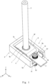
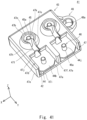
- Fig. 1 is a perspective view of the terminal block of the present embodiment as seen from the positive side of the Z-axis.
- Fig. 2 is a view of the terminal block of the present embodiment as seen from the positive side of the Z-axis.
- Fig. 3 is a cross-sectional view along line III-III in Fig. 2 .
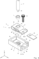
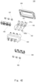
- Fig. 4 is an exploded perspective view of the terminal block of the present embodiment.
- a terminal block 1 is used to electrically connect a first conductive member 2 and a second conductive member 3.
- the first conductive member 2 is a substantially cylindrical bus bar extending in the Z-axis direction, for example.
- the second conductive member 3 is a plate-shaped bus bar substantially parallel with the XY plane and extending in the Y-axis direction, for example.
- the terminal block 1 includes a terminal 4 and a housing 5.
- the terminal 4 includes a terminal body 6, a first connection portion 7, and a second connection portion 8.
- the terminal body 6 is a bent body obtained by bending a conductive material, such as a belt-like metallic plate, extending in the Y-axis direction into a substantially flat spiral shape.
- Fig. 5 is a perspective view of the terminal body in the terminal block of the present embodiment as seen from the positive side of the Z-axis.
- Fig. 6 is a perspective view of the terminal body in the terminal block of the present embodiment as seen from the negative side of the Z-axis.
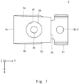
- Fig. 7 is a view of the terminal body in the terminal block of the present embodiment as seen from the positive side of the Z-axis.
- the terminal body 6 includes a first plate portion 6a, a second plate portion 6b, a first coupling portion 6c, a third plate portion 6d, and a second coupling portion 6e.
- the first plate portion 6a is substantially parallel with the XY plane, and extends in the Y-axis direction.
- the first plate portion 6a has a substantially trapezoidal shape such that its width dimension in the X-axis direction decreases along a direction toward the positive side of the Y-axis as seen in the Z-axis direction, for example.
- the first plate portion 6a has formed therein a first penetrating hole 6f penetrating the first plate portion 6a in the Z-axis direction.
- the first penetrating hole 6f is substantially circular in shape as seen in the Z-axis direction, for example.
- the first penetrating hole 6f is disposed in substantially the center of the first plate portion 6a as seen in the Z-axis direction, for example.
- the second plate portion 6b is roughly and substantially parallel with the XY plane, and extends in the Y-axis direction.
- the second plate portion 6b is substantially rectangular in shape as seen in the Z-axis direction.
- the width dimension of the second plate portion 6b in the X-axis direction is substantially equal to the width dimension of an end portion, which is located on the negative side of the Y-axis, of the first plate portion 6a in the X-axis direction.
- the second plate portion 6b is disposed to overlap the first plate portion 6a in the Z-axis direction.
- the second plate portion 6b is disposed on the negative side of the Z-axis with respect to the first plate portion 6a.
- An end portion, which is located on the negative side of the Y-axis, of the second plate portion 6b is disposed at substantially the same position as the end portion, which is located on the negative side of the Y-axis, of the first plate portion 6a as seen in the Z-axis direction.
- An end portion, which is located on the positive side of the Y-axis, of the second plate portion 6b protrudes to the positive side of the Y-axis beyond an end portion, which is located on the positive side of the Y-axis, of the first plate portion 6a as seen in the Z-axis direction.
- the second plate portion 6b has formed therein a second penetrating hole 6g penetrating the second plate portion 6b in the Z-axis direction.
- the second penetrating hole 6g is substantially circular in shape as seen in the Z-axis direction, for example, and is disposed to substantially overlap the first penetrating hole 6f.
- the end portion, which is located on the positive side of the Y-axis, of the second plate portion 6b has formed therein a third penetrating hole 6h penetrating the second plate portion 6b in the Z-axis direction.
- the third penetrating hole 6h functions as the second connection portion 8 as described below.
- the end portion, which is located on the positive side of the Y-axis, of the second plate portion 6b may be wider in the X-axis direction than the other portions.
- the end portion, which is located on the positive side of the Y-axis, of the second plate portion 6b may have a horizontally-oriented C-shape as seen in the Y-axis direction. That is, upright portions 6i may be provided at opposite ends in the X-axis direction of the end portion, which is located on the positive side of the Y-axis, of the second plate portion 6b such that the upright portions 6i extend upward to the positive side of the Z-axis.
- Each of the upright portions 6i is substantially rectangular in shape as seen in the X-axis direction, for example.
- the second plate portion 6b has formed therein cutout portions 6j each having a substantially right triangular shape such that the width dimension of the second plate portion 6b in the X-axis direction decreases along a direction toward a region of the end portion, which is located on the positive side of the Y-axis, of the second plate portion 6b where the upright portions 6i are formed as seen in the Z-axis direction, but such cutout portions 6j may be omitted.
- the width dimension of the first coupling portion 6c in the X-axis direction is substantially equal to the width dimension of the end portion, which is located on the negative side of the Y-axis, of the first plate portion 6a in the X-axis direction. As shown in Figs.
- an end portion, which is located on the positive side of the Z-axis, of the first coupling portion 6c is continuous with the end portion, which is located on the negative side of the Y-axis, of the first plate portion 6a, while an end portion, which is located on the negative side of the Z-axis, of the first coupling portion 6c is continuous with the end portion, which is located on the negative side of the Y-axis, of the second plate portion 6b.
- the third plate portion 6d is substantially parallel with the XY plane, and extends in the Y-axis direction.
- the third plate portion 6d is substantially rectangular in shape as seen in the Z-axis direction.
- the width dimension of the third plate portion 6d in the X-axis direction is substantially equal to the width dimension of the end portion, which is located on the positive side of the Y-axis, of the first plate portion 6a in the X-axis direction.
- the third plate portion 6d is disposed between the first plate portion 6a and the second plate portion 6b.
- the length of the third plate portion 6d in the Y-axis direction is smaller than the length of the first plate portion 6a in the Y-axis direction.
- an end portion, which is located on the positive side of the Y-axis, of the third plate portion 6d is disposed at substantially the same position as the end portion, which is located on the positive side of the Y-axis, of the first plate portion 6a as seen in the Z-axis direction.
- an end portion, which is located on the negative side of the Y-axis, of the third plate portion 6d is disposed on the negative side of the Y-axis with respect to the first penetrating hole 6f as seen in the Z-axis direction.
- the third plate portion 6d has a fourth penetrating hole 6k penetrating the third plate portion 6d in the Z-axis direction.
- the fourth penetrating hole 6k is substantially circular in shape as seen in the Z-axis direction, for example, and may be disposed substantially concentrically with the first penetrating hole 6f.
- the fourth penetrating hole 6k is large enough to pass an external thread portion 2a formed on an end portion, which is located on the negative side of the Z-axis, of the first conductive member 2.
- the second coupling portion 6e couples the end portion, which is located on the positive side of the Y-axis, of the first plate portion 6a to the end portion, which is located on the positive side of the Y-axis, of the third plate portion 6d.
- the second coupling portion 6e is curved such that it protrudes to the positive side of the Y-axis as seen in the X-axis direction, for example.
- the width dimension of the second coupling portion 6e in the X-axis direction is substantially equal to the width dimension of the end portion, which is located on the positive side of the Y-axis, of the first plate portion 6a in the X-axis direction. As shown in Figs.
- an end portion, which is located on the positive side of the Z-axis, of the second coupling portion 6e is continuous with the end portion, which is located on the positive side of the Y-axis, of the first plate portion 6a, while an end portion, which is located on the negative side of the Z-axis, of the second coupling portion 6e is continuous with the end portion, which is located on the positive side of the Y-axis, of the third plate portion 6d.
- Such a terminal body 6 is shaped such that the first plate portion 6a, the second plate portion 6b, and the third plate portion 6d are disposed to overlap in the Z-axis direction such that they are substantially parallel with each other.
- the terminal body 6 is shaped such that it is bent into a flat spiral shape so as to allow the third plate portion 6d, the second coupling portion 6e, the first plate portion 6a, the first coupling portion 6c and the second plate portion 6b to be continuous.
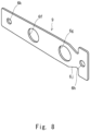
- FIG. 8 is a view for illustrating a production flow for the terminal body in the terminal block of the present embodiment.
- a belt-like material 9 which has the fourth penetrating hole 6k, the first penetrating hole 6f, the second penetrating hole 6g, and the third penetrating hole 6h sequentially formed therein, and also has the cutout portions 6j formed at predetermined positions, is obtained out of a conductive material, such as a metallic plate, through punching.
- the belt-like material 9 is bent at a position between the fourth penetrating hole 6k and the first penetrating hole 6f so that the third plate portion 6d and the second coupling portion 6e are formed.
- the belt-like material 9 is bent at a position between the first penetrating hole 6f and the second penetrating hole 6g so that the first plate portion 6a is formed.
- the upright portions 6i are formed on the end portion, which is located on the positive side of the Y-axis, of the second plate portion 6b. Accordingly, the terminal body 6 such as the one shown in Figs. 5 to 7 can be produced. In this manner, bending the belt-like material 9 into a flat spiral shape can easily produce the terminal body 6. Note that the upright portions 6i may be formed before the belt-like material 9 is bent.
- the first connection portion 7 is disposed on the third plate portion 6d that is one end portion of the terminal body 6.
- the first connection portion 7 includes a nut that is a representative example of a connection member into which the external thread portion 2a of the first conductive member 2 is adapted to be screwed, for example.
- the first connection portion 7 is fixed to a face, which is located on the positive side of the Z-axis, of the third plate portion 6d in a state where the first connection portion 7 is disposed substantially concentrically with the fourth penetrating hole 6k as seen in the Z-axis direction, for example.
- the end portion, which is located on the positive side of the Z-axis, of the first connection portion 7 may protrude to the positive side of the Z-axis from the first penetrating hole 6f of the terminal body 6 in a state where the first connection portion 7 is passed through the first penetrating hole 6f.
- a gap which is adapted to tolerate the displacement of the first connection portion 7 in the X-axis direction and the Y-axis direction, may be formed between the outer peripheral side surface of the first connection portion 7 and the circumferential portion of the first penetrating hole 6f of the terminal body 6.
- the second connection portion 8 is disposed on the end portion, which is located on the positive side of the Y-axis, of the second plate portion 6b that is the other end portion of the terminal body 6.
- the second connection portion 8 includes the third penetrating hole 6h, for example, and is adapted to pass a bolt 10 that has been passed through a penetrating hole 3a formed in the second conductive member 3.
- the housing 5 accommodates the terminal 4.
- the housing 5 is a molded product of an insulating material, such as resin, for example.
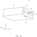
- Fig. 12 is a perspective view of the housing of the terminal block of the present embodiment as seen from the positive side of the Z-axis.
- Fig. 13 is a perspective view of the housing of the terminal block of the present embodiment as seen from the negative side of the Z-axis.
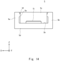
- Fig. 14 is a view of the housing of the terminal block of the present embodiment as seen from the positive side of the Y-axis.
- the housing 5 has a hollow, substantially rectangular parallelepiped shape.
- the housing 5 is open on the positive side of the Y-axis and on the positive side of the Z-axis. That is, the housing 5 includes a first sidewall portion 5a, a second sidewall portion 5b, a third sidewall portion 5c, and a bottom portion 5d.
- the first sidewall portion 5a is in the shape of a plate that is substantially parallel with the YZ plane, and extends in the Y-axis direction.
- the second sidewall portion 5b is disposed facing the first sidewall portion 5a in the X-axis direction, and is disposed on the negative side of the X-axis with respect to the first sidewall portion 5a.
- the second sidewall portion 5b is in the shape of a plate that is substantially parallel with the YZ plane, and extends in the Y-axis direction.
- the gap between the first sidewall portion 5a and the second sidewall portion 5b in the X-axis direction is substantially equal to the width dimension of the end portion, which is located on the positive side of the Y-axis, of the second plate portion 6b of the terminal 4, for example.
- first protruding portions 5e which protrude to face each other in the X-axis direction, may be respectively formed on a corner portion, which is located on the positive side of the Y-axis and on the positive side of the Z-axis, of the first sidewall portion 5a and on a corner portion, which is located on the positive side of the Y-axis and on the positive side of the Z-axis, of the second sidewall portion 5b.
- Each first protruding portion 5e is substantially rectangular in shape as seen in the X-axis direction, for example.
- each first protruding portions 5e in the X-axis direction may be substantially equal to the thickness of each upright portion 6i of the terminal 4 in the X-axis direction.
- an end portion, which is located on the positive side of the Z-axis, of each first protruding portion 5e may have formed thereon an inclined surface 5f that is inclined toward the other first protruding portions 5e along a direction toward the negative side of the Z-axis.
- the third sidewall portion 5c is in the shape of a plate that is substantially parallel with the XZ plane, and extends in the X-axis direction.
- An end portion, which is located on the positive side of the X-axis, of the third sidewall portion 5c is continuous with an end portion, which is located on the negative side of the Y-axis, of the first sidewall portion 5a, while an end portion, which is located on the negative side of the X-axis, of the third sidewall portion 5c is continuous with an end portion, which is located on the negative side of the Y-axis, of the second sidewall portion 5b. Therefore, the first sidewall portion 5a, the second sidewall portion 5b, and the third sidewall portion 5c form a substantial C-shape as seen in the Z-axis direction.
- the bottom portion 5d is substantially rectangular in shape as seen in the Z-axis direction.
- the bottom portion 5d is roughly in the shape of a plate that is substantially parallel with the XY plane.
- the first sidewall portion 5a protrudes to the positive side of the Z-axis from an end portion, which is located on the positive side of the X-axis, of the bottom portion 5d.
- the second sidewall portion 5b protrudes to the positive side of the Z-axis from an end portion, which is located on the negative side of the X-axis, of the bottom portion 5d.
- the third sidewall portion 5c protrudes to the positive side of the Z-axis from an end portion, which is located on the negative side of the Y-axis, of the bottom portion 5d.
- a face, which is located on the positive side of the Z-axis, of the bottom portion 5d has a stepped shape. That is, the face, which is located on the positive side of the Z-axis, of the bottom portion 5d has formed thereon a first portion 5g and a second portion 5h disposed on the positive side of the Z-axis with respect to the first portion 5g.
- the first portion 5g is substantially rectangular in shape as seen in the Z-axis direction, for example.
- a portion, which is located on the negative side of the Y-axis, of the second plate portion 6b of the terminal 4 is disposed in a space on the positive side of the Z-axis with respect to the first portion 5g, as opposed to the end portion, which is located on the positive side of the Y-axis, of the second plate portion 6b of the terminal 4.
- the first portion 5g has formed thereon a second protruding portion 5i protruding to the positive side of the Z-axis.
- the second protruding portion 5i has an annular shape as seen in the Z-axis direction, for example.
- the outside diameter of the second protruding portion 5i is smaller than the diameter of the second penetrating hole 6g of the terminal 4.
- the second portion 5h is disposed on the positive side of the Y-axis with respect to the first portion 5g, and is substantially rectangular in shape as seen in the Z-axis direction, or example.
- the end portion, which is located on the positive side of the Y-axis, of the second plate portion 6b of the terminal 4 is disposed in a space on the positive side of the Z-axis with respect to the second portion 5h.
- the second portion 5h has formed therein a penetrating hole 5j adapted to pass the bolt 10 that has been passed through the third penetrating hole 6h of the terminal 4.
- the gap between the face, which is located on the positive side of the Z-axis, of the second portion 5h and an end portion, which is located on the negative side of the Z-axis, of each first protruding portion 5e may be substantially equal to the height of each upright portion 6i of the terminal 4 in the Z-axis direction.
- the end portion, which is located on the positive side of the Y-axis, of the second plate portion 6b of the terminal 4 is placed on the face, which is located on the positive side of the Z-axis, of the second portion 5h of the bottom portion 5d of the housing 5, and the upright portions 6i of the terminal 4 are inserted into a space between the second portion 5h and the first protruding portions 5e.
- the face, which is located on the positive side of the Z-axis, of the second portion 5h of the bottom portion 5d of the housing 5 functions as a determination plane for determining the height position of the terminal 4 in the housing 5 in the Z-axis direction.
- a gap that allows a portion, which is located on the negative side of the Y-axis, of the second plate portion 6b of the terminal 4 to deform in the X-axis direction, the Y-axis direction, and the Z-axis direction as opposed to the end portion, which is located on the positive side of the Y-axis, of the second plate portion 6b of the terminal 4 is formed between the terminal 4 and the inner peripheral side surface of the housing 5.
- the housing 5 when the terminal block 1 is assembled, it is possible to allow the housing 5 to restrain the position of the terminal 4 in the X-axis direction and the Z-axis direction if the gap between the first sidewall portion 5a and the second sidewall portion 5b of the housing 5 in the X-axis direction is substantially equal to the width dimension of the end portion, which is located on the positive side of the Y-axis, of the second plate portion 6b of the terminal 4, and the gap between the face, which is located on the positive side of the Z-axis, of the second portion 5h of the bottom portion 5d of the housing 5 and the end portion, which is located on the negative side of the Z-axis, of each first protruding portion 5e is substantially equal to the height of each upright portion 6i of the terminal 4 in the Z-axis direction.
- the external thread portion 2a of the first conductive member 2 is screwed into the first connection portion 7 of the terminal 4 while the first conductive member 2 is passed through the first penetrating hole 6f of the terminal 4 from the positive side of the Z-axis.
- an end portion, which is located on the negative side of the Z-axis, of the external thread portion 2a of the first conductive member 2 may be passed through the fourth penetrating hole 6k of the terminal 4.
- the second conductive member 3 is placed on the end portion, which is located on the positive side of the Y-axis, of the second plate portion 6b of the terminal 4 from the positive side of the Z-axis, and the penetrating hole 3a of the second conductive member 3, the third penetrating hole 6h of the terminal 4, and the penetrating hole 5j of the housing 5 are disposed substantially concentrically as seen in the Z-axis direction.
- the bolt 10 is passed through the penetrating hole 3a of the second conductive member 3, the third penetrating hole 6h of the terminal 4, and the penetrating hole 5j of the housing 5 from the positive side of the Z-axis, and is then screwed into an internal thread of an electronic component (not shown). Accordingly, the first conductive member 2 and the second conductive member 3 can be electrically connected to the terminal block 1, and also, the terminal block 1 can be fixed to the electronic component.
- Fig. 15 is a view showing the state of the terminal in the terminal block of the present embodiment that has deformed toward the negative side of the Z-axis, as seen from the positive side of the X-axis.
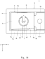
- Fig. 16 is a view showing the state of the terminal in the terminal block of the present embodiment that has deformed toward the negative side of the X-axis, as seen from the positive side of the Z-axis.
- Fig. 17 is a view showing the state of the terminal body in the terminal block of the present embodiment that has deformed toward the negative side of the X-axis, as seen from the positive side of the X-axis.
- Fig. 18 is a view showing the state of the terminal in the terminal block of the present embodiment that has deformed toward the positive side of the Y-axis, as seen from the positive side of the X-axis.
- the third plate portion 6d of the terminal 4 is pushed to the negative side of the Z-axis when a force acts on the first connection portion 7 of the terminal 4 toward the negative side of the Z-axis and thus causes the first connection portion 7 to be displaced to the negative side of the Z-axis.
- the first plate portion 6a of the terminal 4 deforms such that it is inclined toward the negative side of the Z-axis along the direction toward the positive side of the Y-axis
- the second plate portion 6b of the terminal 4 deforms such that it is inclined toward the negative side of the Z-axis along the direction toward the negative side of the Y-axis.
- the third plate portion 6d may contact the second protruding portion 5i of the housing 5 so that the deformation of the third plate portion 6d toward the negative side of the Z-axis is restricted.
- the third plate portion 6d of the terminal 4 is pushed to the negative side of the X-axis when a force acts on the first connection portion 7 of the terminal 4 toward the negative side of the X-axis and thus causes the first connection portion 7 to be displaced to the negative side of the X-axis.
- the first plate portion 6a deforms such that it rotates counterclockwise
- the second plate portion 6b deforms such that it rotates clockwise as seen from the positive side of the Z-axis.
- each of the first plate portion 6a and the second plate portion 6b of the terminal 4 is twisted clockwise along the direction toward the negative side of the Y-axis, and the third plate portion 6d of the terminal 4 is twisted counterclockwise along the direction toward the negative side of the Y-axis as seen from the positive side of the Y-axis.
- the first plate portion 6a of the terminal 4 has a substantially trapezoidal shape such that its width dimension in the X-axis direction decreases along the direction toward the positive side of the Y-axis, it is possible to, when the first connection portion 7 is displaced in the X-axis direction, prevent the first plate portion 6a from coming into contact with the housing 5, and thus allow the first connection portion 7 to be favorably displaced in the X-axis direction.
- the third plate portion 6d of the terminal 4 is pushed to the positive side of the Y-axis when a force acts on the first connection portion 7 of the terminal 4 toward the positive side of the Y-axis and thus causes the first connection portion 7 to be displaced to the positive side of the Y-axis.
- the third plate portion 6d of the terminal 4 is pushed to the positive side of the Y-axis, the first plate portion 6a and the second plate portion 6b deform such that they are inclined toward the positive side of the Z-axis along the direction toward the negative side of the Y-axis.
- the third plate portion 6d of the terminal 4 deforms such that it is inclined toward the negative side of the Z-axis along the direction toward the negative side of the Y-axis.
- the terminal block 1 of the present embodiment is configured such that the terminal body 6 is deformable in all directions including the X-axis direction, the Y-axis direction, and the Z-axis direction, and thus is able to absorb the positional displacement of the first conductive member 2 with respect to the terminal block 1. Therefore, the terminal block 1 of the present embodiment allows the first conductive member 2 to be favorably connected to the terminal block 1.
- the terminal body 6 of the present embodiment is shaped such that the first plate portion 6a, the second plate portion 6b, and the third plate portion 6d are disposed to overlap in the Z-axis direction such that they are substantially parallel with one another. Therefore, the deformations of the plate portions of the terminal body 6 can be cancelled out each other, and the third plate portion 6d can thus be maintained substantially parallel with the XY plane as described above.
- the first conductive member 2 can be easily connected to the first connection portion 7 of the terminal 4. That is, the terminal block 1 of the present embodiment has high connectivity to the first conductive member 2.
- the terminal body 6 of the present embodiment is shaped such that it is bent into a flat spiral shape so as to allow the third plate portion 6d, the second coupling portion 6e, the first plate portion 6a, the first coupling portion 6c, and the second plate portion 6b to be continuous. That is, since the terminal body 6 is bent to have the third plate portion 6d located on the inner side thereof, it is possible to absorb the positional displacement of the first conductive member 2 with respect to the terminal block 1 while avoiding an increase in the size of the terminal body 6, and further, the terminal block 1. This contributes to reducing the size of the terminal block 1.
- the terminal body 6 of the present embodiment can be easily produced by bending the belt-like material 9 into a flat spiral shape.
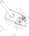
- Fig. 19 is a perspective view of the terminal block of the present embodiment as seen from the positive side of the Z-axis.
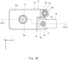
- Fig. 20 is a view of the terminal block of the present embodiment as seen from the positive side of the Z-axis.
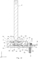
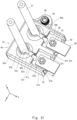
- Fig. 21 is a cross-sectional view along line XXI-XXI in Fig. 20 .
- Fig. 22 is an exploded perspective view of the terminal block of the present embodiment.
- Fig. 23 is a view of the terminal block of the present embodiment as seen from the negative side of the Z-axis. Note that a terminal block 21 of the present embodiment has substantially the same configuration as the terminal block 1 of Embodiment 1. Thus, the overlapped description will be omitted.
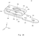
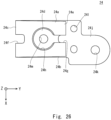
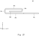
- the terminal body 24 includes a first plate portion 24a, a second plate portion 24b, a first coupling portion 24c, a third plate portion 24d, and a second coupling portion 24e, and further includes a first slit portion 24f and a second slit portion 24g.
- the first slit portion 24f is formed continuously in the first plate portion 24a, the first coupling portion 24c, and the second plate portion 24b so as to reach an end portion, which is located on the negative side of the Y-axis, of the second plate portion 24b from an end portion, which is located on the negative side of the Y-axis, of the first plate portion 24a via the first coupling portion 24c.
- the first slit portion 24f is disposed on a line passing through the surfaces of the first plate portion 24a, the first coupling portion 24c, and the second plate portion 24b, and connecting the center of a first penetrating hole 24h in the first plate portion 24a to the center of a second penetrating hole 24i in the second plate portion 24b.
- an end portion, which is located on the positive side of the Y-axis, of the second plate portion 24b has a bent portion 24j formed thereon.
- the bent portion 24j is substantially L-shaped as seen in the Z-axis direction, for example, and extends to the positive side of the X-axis, and further extends to the positive side of the Y-axis.
- an end portion on the distal end side (i.e., on the positive side of the Y-axis) of the bent portion 24j has a third penetrating hole 24k formed therein.
- an end portion on the proximal side (i.e., on the negative side of the Y-axis) of the bent portion 24j has formed therein fourth penetrating holes 24l that are spaced apart in the X-axis direction.
- the second slit portion 24g is formed continuously in the first plate portion 24a, the second coupling portion 24e, and the third plate portion 24d so as to reach an end portion, which is located on the positive side of the Y-axis, of the third plate portion 24d from the first penetrating hole 24h of the first plate portion 24a via the second coupling portion 24e.
- the second slit portion 24g is disposed on a line passing through the surfaces of the first plate portion 24a, the second coupling portion 24e, and the third plate portion 24d, and connecting the center of the first penetrating hole 24h in the first plate portion 24a to the center of a fifth penetrating hole 24m in the third plate portion 24d.
- the first connection portion 25 includes a bolt that is a representative example of a connection member adapted to be screwed into an internal thread portion 27a formed in an end portion, which is located on the negative side of the Z-axis, of a first conductive member 27.
- the first connection portion 25 is fixed to the third plate portion 24d of the terminal body 24 by being sandwiched from the opposite sides of the first connection portion 25 in the Z-axis direction with a crimp jig, which has been passed through the first penetrating hole 24h and the second penetrating hole 24i of the terminal body 24, in a state where a shaft portion 25a of the first connection portion 25 is passed through the fifth penetrating hole 24m of the terminal body 24 from the negative side of the Z-axis.
- the second connection portion 26 includes a bolt that is a representative example of a connection member adapted to be passed through a penetrating hole 28a formed in an end portion, which is located on the negative side of the Y-axis, of a second conductive member 28 and through the third penetrating hole 24k of the terminal body 24.
- the second connection portion 26 is fixed to the second plate portion 24b of the terminal body 24 by being sandwiched from the opposite sides of the second connection portion 26 in the Z-axis direction with a crimp jig in a state where a shaft portion 26a of the second connection portion 26 is passed through the third penetrating hole 24k of the terminal body 24 from the negative side of the Z-axis.
- the housing 23 accommodates the terminal 22.
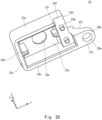
- Fig. 28 is a perspective view of the housing of the terminal block of the present embodiment as seen from the negative side of the Z-axis.
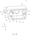
- Fig. 29 is a different perspective view of the housing of the terminal block of the present embodiment as seen from the negative side of the Z-axis.
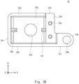
- Fig. 30 is a view of the housing of the terminal block of the present embodiment as seen from the negative side of the Z-axis.
- the housing 23 has a roughly hollow, substantially rectangular parallelepiped shape.
- the housing 23 is open on the negative side of the Z-axis. That is, the housing 23 includes a first sidewall portion 23a, a second sidewall portion 23b, a third sidewall portion 23c, a fourth sidewall portion 23d, and a ceiling portion 23e.
- the first sidewall portion 23a and the second sidewall portion 23b are disposed facing each other in the X-axis direction.
- the third sidewall portion 23c and the fourth sidewall portion 23d are disposed facing each other in the Y-axis direction.
- an end portion, which is located on the negative side of the Z-axis, of the fourth sidewall portion 23d disposed on the positive side of the Y-axis has formed therein a cutout portion 23f for allowing the distal end portion of the bent portion 24j of the terminal 22 to protrude to the positive side of the Y-axis from the housing 23.
- a face, which is located on the positive side of the Z-axis, of the cutout portion 23f is a flat face substantially parallel with the XY plane, for example.
- bosses 23g which are adapted to be passed through the respective fourth penetrating holes 24l of the terminal 22, protrude to the negative side of the Z-axis from the face, which is located on the positive side of the Z-axis, of the cutout portion 23f. As shown in Figs. 28 to 30 , bosses 23g, which are adapted to be passed through the respective fourth penetrating holes 24l of the terminal 22, protrude to the negative side of the Z-axis from the face, which is located on the positive side of the Z-axis, of the cutout portion 23f. As shown in Figs.
- each boss 23g allows the terminal 22 to be fixed to the housing 23 as an end portion, which is located on the negative side of the Z-axis, of the boss 23g is squashed with heat in a state where the boss 23g is passed through the fourth penetrating hole 24l of the terminal 22 and the second plate portion 24b of the terminal 22 is substantially in surface contact with the face, which is located on the positive side of the Z-axis, of the cutout portion 23f of the housing 23.
- the face, which is located on the positive side of the Z-axis, of the cutout portion 23f functions as a determination plane for determining the height position of the terminal 22 in the housing 23 in the Z-axis direction.
- the third sidewall portion 23c may have formed thereon a first reinforcement rib 23h such that the first reinforcement rib 23h protrudes to the positive side of the Y-axis from the third sidewall portion 23c.
- the first reinforcement rib 23h extends in the Z-axis direction, and is substantially rectangular in shape as seen in the X-axis direction.
- the first reinforcement rib 23h is disposed in the first slit portion 24f of the terminal 22.
- first reinforcement rib 23h and the second reinforcement rib 23i in the housing 23 can improve the rigidity of the housing 23. Further, this can also avoid an increase in the size of the terminal block 21 because the first reinforcement rib 23h is disposed in the first slit portion 24f of the terminal 22 and the second reinforcement rib 23i is disposed in the second slit portion 24g of the terminal 22.
- the fourth sidewall portion 23d has formed thereon a fixation portion 23j protruding to the positive side of the Y-axis from an end portion, which is located on the negative side of the X-axis, of the fourth sidewall portion 23d.
- the fixation portion 23j is in the shape of a plate that is substantially parallel with the XY plane, and is substantially rectangular in shape as seen in the Z-axis direction.
- an end portion, which is located on the positive side of the Y-axis, of the fixation portion 23j may have a chamfered portion 23k formed thereon.
- the fixation portion 23j may be reinforced with a third reinforcement rib 231 from the opposite sides of the fixation portion 23j in the X-axis direction.
- the third reinforcement rib 231 has a substantially right triangular shape as seen in the X-axis direction, for example.
- the fixation portion 23j has a first penetrating hole 23m formed therein.
- the ceiling portion 23e has a second penetrating hole 23n formed therein. As shown in Figs. 19 to 21 , the second penetrating hole 23n is adapted to pass the first conductive member 27.
- the distal end portion of the bent portion 24j of the terminal 22 is caused to protrude to the positive side of the Y-axis from the cutout portion 23f of the housing 23 while a portion of the terminal 22, which is located on the negative side of the Y-axis with respect to the bent portion 24j, is accommodated in the housing 23 from the negative side of the Z-axis.
- the bosses 23g of the housing 23 are passed through the respective fourth penetrating holes 24l of the terminal 22, and also, the second plate portion 24b of the terminal 22 is caused to be substantially in surface contact with the face, which is located on the positive side of the Z -axis, of the cutout portion 23f of the housing 23.
- the first reinforcement rib 23h of the housing 23 is disposed in the first slit portion 24f of the terminal 22, and also, the second reinforcement rib 23i of the housing 23 is disposed in the second slit portion 24g of the terminal 22.
- each boss 23g of the housing 23 is squashed with heat so as to allow the bent portion 24j of the terminal 22 to be sandwiched between the end portion, which is located on the negative side of the Z-axis, of the boss 23g of the housing 23 and the face, which is located on the positive side of the Z-axis, of the cutout portion 23f, so that the terminal 22 is fixed to the housing 23. Accordingly, the assembly of the terminal block 21 is complete.
- the collar 30 is disposed in the first penetrating hole 23m of the housing 23. Then, the bolt 29 is passed through the collar 30 so as to be screwed into an internal thread portion of the electronic component, so that the terminal block 21 is fixed to the electronic component.
- the shaft portion 25a of the first connection portion 25 of the terminal 22 is screwed into the internal thread portion 27a of the first conductive member 27 while the first conductive member 27 is passed through the second penetrating hole 23n of the housing 23 and through the first penetrating hole 24h of the terminal 22 from the positive side of the Z -axis, so that the first conductive member 27 is electrically connected to the terminal block 21.
- the shaft portion 26a of the second connection portion 26 is passed through the penetrating hole 28a of the second conductive member 28 so that the second conductive member 28 is placed on the distal end portion of the bent portion 24j of the terminal 22, and a nut 31 is screwed around the shaft portion 26a of the second connection portion 26 from the positive side of the Z-axis.
- This allows the second conductive member 28 to be electrically connected to the terminal block 21.
- the terminal block 21 can be fixed to the electronic component, and also, the first conductive member 27 and the second conductive member 28 can be electrically connected to the terminal block 21.
- Such a terminal block 21 is also configured such that, as with the terminal block 1 of Embodiment 1, the terminal body 24 is deformable in all directions including the X-axis direction, the Y-axis direction, and the Z-axis direction, and thus is able to absorb the positional displacement of the first conductive member 27 with respect to the terminal block 21. Therefore, the terminal block 21 of the present embodiment allows the first conductive member 27 to be favorably connected to the terminal block 21.
- the terminal body 24 of the present embodiment is also bent to have the third plate portion 24d located on the inner side thereof, it is possible to absorb the positional displacement of the first conductive member 27 with respect to the terminal block 21 while avoiding an increase in the size of the terminal body 24, and further, the terminal block 21. This contributes to reducing the size of the terminal block 21.
- the terminal body 24 of the present embodiment since the terminal body 24 of the present embodiment has the first slit portion 24f and the second slit portion 24g formed therein, the terminal body 24 is more easily deformable in comparison with the terminal body 6 of Embodiment 1. Therefore, the terminal block 21 of the present embodiment is able to more easily absorb the positional displacement of the first conductive member 27 with respect to the terminal block 21 in comparison with the terminal block 1 of Embodiment 1, and thus, the first conductive member 27 can be favorably connected to the terminal block 21.
- the housing 23 has the first reinforcement rib 23h and the second reinforcement rib 23i formed thereon, the rigidity of the housing 23 can be improved. Further, when the first reinforcement rib 23h is disposed in the first slit portion 24f of the terminal 22, and the second reinforcement rib 23i is disposed in the second slit portion 24g of the terminal 22, an increase in the size of the terminal block 21 can be avoided.
- the second slit portion 24g is formed continuously in the first plate portion 24a, the second coupling portion 24e, the third plate portion 24d of the terminal body 24, the second slit portion 24g need not be continuous, and may be formed in at least one of the first plate portion 24a, the second coupling portion 24e, or the third plate portion 24d.
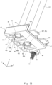
- Fig. 31 is a perspective view of the terminal block of the present embodiment as seen from the positive side of the Z-axis.
- Fig. 32 is a perspective view of the terminal block of the present embodiment as seen from the negative side of the Z-axis.
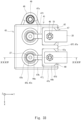
- Fig. 33 is a view of the terminal block of the present embodiment as seen from the positive side of the Z-axis.
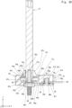
- Fig. 34 is a cross-sectional view along line XXXIV-XXXIV in Fig. 33 .
- a terminal block 41 of the present embodiment has substantially the same configuration as the terminal block 1 of Embodiment 1 and the like. Thus, the overlapped description will be omitted.
- the terminal block 41 includes terminals 42 on the positive side of the X-axis and on the negative side of the X-axis, and a housing 43.
- the terminal 42 on the positive side of the X-axis and the terminal 42 on the negative side of the X-axis have the same configuration, the configuration of the terminal 42 on the positive side of the X-axis will be described as a representative example.
- the terminal 42 has substantially the same configuration as the terminal 22 of Embodiment 2, and specifically includes a terminal body 44, a first connection portion 45, and a second connection portion 46.
- the terminal body 44 is also a bent body obtained by bending a conductive material, such as a belt-like metallic plate, into a substantial spiral shape.
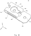
- Fig. 35 is a perspective view of the terminal body in the terminal block of the present embodiment as seen from the positive side of the Z-axis.
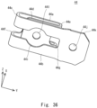
- Fig. 36 is a perspective view of the terminal body in the terminal block of the present embodiment as seen from the negative side of the Z-axis.
- Fig. 37 is a view of the terminal body in the terminal block of the present embodiment as seen from the positive side of the Z-axis.
- Fig. 38 is a view of the terminal body in the terminal block of the present embodiment as seen from the negative side of the Z-axis.
- the terminal body 44 includes a first plate portion 44a, a second plate portion 44b, a first coupling portion 44c, a third plate portion 44d, a second coupling portion 44e, a first slit portion 44f, and a second slit portion 44g.
- an end portion, which is located on the positive side of the Y-axis, of the second plate portion 44b has a third penetrating hole 44j formed therein, and the second connection portion 46 is fixed in a state where a shaft portion 46a of the second connection portion 46 is passed through the third penetrating hole 44j.
- the second connection portion 46 may include a bolt as with the second connection portion 26 of Embodiment 2, for example.
- an end portion, which is located on the positive side of the Y-axis, of the second plate portion 44b does not include the bent portion 24j and the fourth penetrating holes 24l unlike the terminal body 24 of Embodiment 2.
- the end portion, which is located on the positive side of the Y-axis, of the second plate portion 44b has formed thereon wider portions 44k that are wider than the other portions in the X-axis direction.
- each wider portion 44k is substantially triangular in shape as seen in the Z-axis direction, for example.
- each wider portion 44k may include an inclined portion such that its width dimension in the X-axis direction increases along the direction toward the positive side of the Y-axis as seen in the Z-axis direction.
- the wider portions 44k on the positive side of the X-axis are disposed at a distance therebetween in the Y-axis direction, and the wider portions 44k on the negative side of the X-axis are disposed at a distance therebetween in the Y-axis direction.
- each wider portion 44k on the positive side of the X-axis and each wider portion 44k on the negative side of the X-axis are disposed facing each other in the X-axis direction.
- the third plate portion 44d has a fourth penetrating hole 44l formed therein, and the first connection portion 45 is fixed in a state where a shaft portion 45a of the first connection portion 45 is passed through the fourth penetrating hole 44l.
- the first slit portion 44f is formed continuously in the first plate portion 44a, the first coupling portion 44c, and the second plate portion 44b. At this time, as shown in Figs. 36 and 38 , the first slit portion 44f may be formed up to a position beyond the second penetrating hole 44i of the second plate portion 44b toward the positive side of the Y-axis, for example.
- the second slit portion 44g is formed continuously in the first plate portion 44a, the second coupling portion 44e, and the third plate portion 44d.
- the housing 43 accommodates the terminals 42.
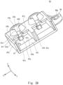
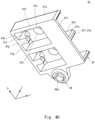
- the housing 43 includes a plurality of (for example, two) accommodation portions 47 arranged in the X-axis direction corresponding to the number of the terminals 42, and a fixation portion 48.
- the plurality of accommodation portions 47 have the same shape.
- the accommodation portion 47 on the positive side of the X-axis will be described as a representative example.
- Fig. 39 is a perspective view of the housing of the terminal block of the present embodiment as seen from the positive side of the Z-axis.
- Fig. 40 is a perspective view of the housing of the terminal block of the present embodiment as seen from the negative side of the Z-axis.
- Fig. 41 is a perspective view showing the state of terminals accommodated in the housing of the terminal block of the present embodiment, as seen from the positive side of the Z-axis.
- the first sidewall portion 47e and the second sidewall portion 47f are disposed facing each other in the X-axis direction.
- the gap between the first sidewall portion 47e and the second sidewall portion 47f in the X-axis direction is substantially equal to the width dimension in the X-axis direction from an end portion, which is located on the positive side of the X-axis, of each wider portion 44k on the positive side of the X-axis of the terminal 42 to an end portion, which is located on the negative side of the X-axis, of each wider portion 44k on the negative side of the X-axis of the terminal 42.
- the second sidewall portion 47f also serves as the first sidewall portions 47e of the body 47a adjacent in the negative side of the X-axis.
- the third sidewall portion 47g is continuous with an end portion, which is located on the negative side of the Y-axis, of the first sidewall portion 47e and with an end portion, which is located on the negative side of the Y-axis, of the second sidewall portion 47f.
- the ceiling portion 47h covers a portion, which is located on the negative side of the Y-axis, of a space surrounded by the first sidewall portion 47e, the second sidewall portion 47f, and the third sidewall portion 47g from the positive side of the Z-axis. Therefore, a first opening 47j, which is continuous, is formed on the positive side of the Y-axis of the body 47a and on the positive side of the Y-axis with respect to the ceiling portion 47h.
- the ceiling portion 47h has a penetrating hole 47k and a cutout portion 47l formed therein.
- the penetrating hole 47k is adapted to pass the shaft portion 45a of the first connection portion 45.
- the penetrating hole 47k, the first penetrating hole 44h of the terminal 42, and the shaft portion 45a of the first connection portion 45 are disposed substantially concentrically as seen in the Z-axis direction.
- the penetrating hole 47k is substantially circular in shape as seen in the Z-axis direction, for example, and the diameter of the penetrating hole 47k is slightly larger than the diameter of the first conductive member 27.
- the cutout portion 47l is formed in the ceiling portion 47h, and extends to the positive side of the Y-axis from the penetrating hole 47k so as to reach an end portion, which is located on the positive side of the Y-axis, of the ceiling portion 47h.
- the width dimension of the cutout portion 47l in the X-axis direction is slightly larger than the diameter of the shaft portion 45a of the first connection portion 45.
- the bottom portion 47i connects a corner portion, which is located on the positive side of the Y-axis and on the negative side of the Z-axis, of the first sidewall portion 47e to a corner portion, which is located on the positive side of the Y-axis and on the negative side of the Z-axis, of the second sidewall portion 47f. Therefore, a second opening 47m is formed on the negative side of the Y-axis with respect to the bottom portion 47i of the body 47a.
- a face, which is located on the positive side of the Z-axis, of the bottom portion 47i has placed thereon an end portion, which is located on the positive side of the Y-axis, of the second plate portion 44b of the terminal 42.
- the face, which is located on the positive side of the Z-axis, of the bottom portion 47i functions as a determination plane for determining the height position of the terminal 42 in the body 47a in the Z-axis direction.
- the protruding portion 47b protrudes to the positive side of the Z-axis from the ceiling portion 47h so as to surround the penetrating hole 47k.
- the protruding portion 47b is substantially annular in shape as seen in the Z-axis direction, for example, and may be substantially conical in shape such that the diameter of the outer peripheral side surface of the protruding portion 47b decreases along the direction toward the positive side of the Z-axis.
- the protruding portion 47b has a penetrating hole 47n and a cutout portion 47o formed therein.
- the cutout portion 47o is formed by partially cutting out the protruding portion 47b toward the positive side of the Y-axis.
- the cutout portion 47o is continuous with the cutout portion 47l of the body 47a in the Z-axis direction.
- the width dimension of the cutout portion 47o in the X-axis direction is substantially equal to the width dimension of the cutout portion 47l of the body 47a in the X-axis direction.
- the reinforcement rib 47c protrudes to the positive side of the Y-axis from the third sidewall portion 47g of the body 47a as with the first reinforcement rib 23h of the housing 23 of Embodiment 2. As shown in Figs. 32 and 34 , the reinforcement rib 47c is disposed in the first slit portion 44f of the terminal 42.
- the reinforcement rib 47c may have formed thereon a horizontal portion 47p protruding to the positive side of the Y-axis from an end portion, which is located on the negative side of the Z-axis, of the reinforcement rib 47c.
- the horizontal portion 47p is disposed on the negative side of the Z-axis with respect to an end portion, which is located on the negative side of the Y-axis, of the third plate portion 44d of the terminal 42.
- the horizontal portion 47p is adapted to come into contact with the end portion, which is located on the negative side of the Y-axis, of the third plate portion 44d of the terminal 42 when the end portion, which is located on the negative side of the Y-axis, of the third plate portion 44d has been displaced to the negative side of the Z-axis by a predetermined displacement amount. This can restrict the displacement amount of the end portion, which is located on the negative side of the Y-axis, of the third plate portion 44d.
- the insertion portion 47d is used to insert the terminal 22 into the body 47a as described above. As shown in Figs. 39 to 41 , the insertion portion 47d is formed of the first opening 47j of the body 47a, the cutout portion 47l of the body 47a, and the cutout portion 47o of the protruding portion 47b.
- the fixation portion 48 has substantially the same shape as the fixation portion 23j of the housing 23 of Embodiment 2, and protrudes to the negative side of the X-axis from the accommodation portion 47 on the negative side of the X-axis, for example.
- the fixation portion 48 has a penetrating hole 48a formed therein.
- a collar 50 which is adapted to pass a bolt 49 used to fix the terminal block 41 to an electronic component, is disposed in the penetrating hole 48a.
- the terminal 42 is inserted into the body 47a from the first opening 47j of the body 47a at the insertion portion 47d of the housing 43 toward the negative side of the Y-axis.
- the shaft portion 45a of the first connection portion 45 of the terminal 42 is passed through the cutout portion 47l of the body 47a and through the cutout portion 47o of the protruding portion 47b at the insertion portion 47d of the housing 43. Further, the shaft portion 45a of the first connection portion 45 of the terminal 42 is passed through the penetrating hole 47k of the body 47a and through the penetrating hole 47n of the protruding portion 47b.
- the shaft portion 45a of the first connection portion 45 of the terminal 42, the first penetrating hole 44h of the terminal 42, the penetrating hole 47k of the body 47a, and the penetrating hole 47n of the protruding portion 47b are disposed substantially concentrically as seen in the Z-axis direction.
- the end portion, which is located on the positive side of the Y-axis, of the second plate portion 44b of the terminal 42 is placed on the face, which is located on the positive side of the Z-axis, of the bottom portion 47i of the body 47a.
- the gap between the first sidewall portion 47e and the second sidewall portion 47f of the body 47a of the housing 43 in the X-axis direction is substantially equal to the width dimension in the X-axis direction from the end portion, which is located on the positive side of the X-axis, of each wider portion 44k on the positive side of the X-axis of the terminal 42 to the end portion, which is located on the negative side of the X-axis, of each wider portion 44k on the negative side of the X-axis of the terminal 42.
- the end portion, which is located on the positive side of the Y-axis, of the second plate portion 44b of the terminal 42 is held by being sandwiched between the first sidewall portion 47e and the second sidewall portion 47f of the body 47a of the housing 43. This allows the terminal 42 to be restrained in the housing 43. Accordingly, the assembly of the terminal block 41 is complete.
- the collar 50 is disposed in the penetrating hole 48a of the fixation portion 48 of the housing 43. Then, the bolt 49 is passed through the collar 50 so as to be screwed into an internal thread portion of the electronic component, so that the terminal block 41 is fixed to the electronic component.
- the shaft portion 45a of the first connection portion 45 of the terminal 42 is screwed into the internal thread portion 27a of the first conductive member 27 while the first conductive member 27 is passed through the penetrating hole 47k of the body 47a and the penetrating hole 47n of the protruding portion 47b in the housing 43 and through the first penetrating hole 44h of the terminal 42 from the positive side of the Z-axis, so that the first conductive member 27 is electrically connected to the terminal block 41.
- the first conductive member 27 is surrounded by the protruding portion 47b of the accommodation portion 47, and comes into contact with the protruding portion 47b when the first conductive member 27 swings. This can restrict the swing of the first conductive member 27.
- the shaft portion 46a of the second connection portion 46 is passed through the penetrating hole 28a of the second conductive member 28 via the first opening 47j of the body 47a at the insertion portion 47d of the housing 43, so that the second conductive member 28 is placed on the end portion, which is located on the positive side of the Y-axis, of the second plate portion 44b of the terminal 42 from the positive side of the Z-axis.
- the terminal block 41 can be fixed to the electronic component, and also, the first conductive member 27 and the second conductive member 28 can be electrically connected to the terminal block 41.
- Such a terminal block 41 is also configured such that, as with the terminal block 1 of Embodiment 1, the terminal body 44 is deformable in all directions including the X-axis direction, the Y-axis direction, and the Z-axis direction, and thus is able to absorb the positional displacement of the first conductive member 27 with respect to the terminal block 41. Therefore, the terminal block 41 of the present embodiment allows the first conductive member 27 to be favorably connected to the terminal block 41.
- the terminal body 44 of the present embodiment is also shaped such that the first plate portion 44a, the second plate portion 44b, and the third plate portion 44d are disposed to overlap in the Z-axis direction such that they are substantially parallel with each other. Therefore, the deformations of the plate portions of the terminal body 44 can be cancelled out each other, and the third plate portion 44d can thus be maintained substantially parallel with the XY plane.
- the first conductive member 27 can be easily connected to the first connection portion 45 of the terminal 42. That is, the terminal block 41 of the present embodiment also has high connectivity to the first conductive member 27.
- the terminal body 44 of the present embodiment is also bent to have the third plate portion 44d located on the inner side thereof, it is possible to absorb the positional displacement of the first conductive member 27 with respect to the terminal block 41 while avoiding an increase in the size of the terminal body 44, and further, the terminal block 41. This contributes to reducing the size of the terminal block 41.
- the housing 43 of the terminal block 41 of the present embodiment has the protruding portion 47b formed thereon, it is possible to, when the first conductive member 27 swings, allow the first conductive member 27 to come into contact with the protruding portion 47b, and thus restrict the swing of the first conductive member 27.
- the reinforcement rib 47c of the housing 43 of the terminal block 41 has the horizontal portion 47p formed thereon, it is possible to, when the end portion, which is located on the negative side of the Y-axis, of the third plate portion 44d of the terminal 42 has been displaced to the negative side of the Z-axis by a predetermined displacement amount, allow the horizontal portion 47p to come into contact with the end portion, which is located on the negative side of the Y-axis, of the third plate portion 44d, and thus restrict the displacement amount of the end portion, which is located on the negative side of the Y-axis, of the third plate portion 44d.
- the housing 43 of the terminal block 41 of the present embodiment has the insertion portion 47d formed therein, it is possible to allow the terminal 42 to be easily inserted into the accommodation portion 47 of the housing 43 toward the negative side of the Y-axis. This allows for easy assembly of the terminal block 41.
- the present disclosure is not limited to the foregoing embodiments, and can be changed as appropriate within the gist of the present disclosure.
- the terminal block 1, 21, or 41 of each of the foregoing embodiments is fixed to an electronic component, but the type of a fixation component to which such a terminal block is fixed is not limited to a particular one. Further, the number, arrangement, shape and the like of the fixation portion(s) of the housing are not limited to particular ones as long as the terminal block can be fixed to the fixation component. Further, a means for fixing the terminal block to the fixation component is not limited to a particular one, either.
- the first conductive member 2 or 27 and the second conductive member 3 or 28 that are electrically connected to the terminal block 1, 21, or 41 of each of the foregoing embodiments are only exemplary. Thus, it is acceptable as long as such conductive members are shaped such that they can be electrically connected to the terminal 4, 22, or 42.
- a means for electrically connecting the first conductive member and the second conductive member to the terminal is not limited to a particular one, either.
- the shape of the terminal body 6, 24, or 44 of the terminal block 1, 21, or 41 and the shape of the housing 5, 23, or 43 of each of the foregoing embodiments is only exemplary. In sum, it is acceptable as long as a terminal is provided that is bent into a flat spiral shape so as to allow the third plate portion, the second coupling portion, the first plate portion, the first coupling portion, and the second plate portion to be continuous, and that allows a first conductive member to be electrically connected to the third plate portion via a penetrating hole formed in the first plate portion.
- the first to third embodiments can be combined as desirable by one of ordinary skill in the art.
Landscapes
- Engineering & Computer Science (AREA)
- Manufacturing & Machinery (AREA)
- Connection Of Batteries Or Terminals (AREA)
- Connections Arranged To Contact A Plurality Of Conductors (AREA)
- Details Of Connecting Devices For Male And Female Coupling (AREA)
- Manufacturing Of Electrical Connectors (AREA)
Abstract
Description
- The present disclosure relates to a terminal block and a method for producing a terminal body.
- A terminal block is typically used to electrically connect a first conductive member and a second conductive member. For example, as shown in
Fig. 42 , aterminal block 100 ofJapanese Unexamined Patent Application Publication No. 2022-61147 first terminal 101 and asecond terminal 102 are inserted into amain housing 104 while being electrically connected together with a braidedwire 103. - At this time, the
first terminal 101 is held in themain housing 104 via afirst sub-housing 105 so that thefirst terminal 101 is movable in a direction perpendicular to the penetration direction of abolt insertion hole 101a of thefirst terminal 101. In addition, thesecond terminal 102 is held in themain housing 104 via asecond sub-housing 106 so that thesecond terminal 102 is movable in a direction perpendicular to the penetration direction of abolt insertion hole 102a of thesecond terminal 102. - Accordingly, even when a first conductive member electrically connected to the
first terminal 101 is displaced with respect to thefirst terminal 101, the braidedwire 103 deforms and allows thefirst terminal 101 to move with respect to themain housing 104. This can absorb the positional displacement of the first conductive member with respect to thefirst terminal 101, and thus allows the first conductive member and thefirst terminal 101 to be electrically connected to anut 107, which is provided in thefirst sub-housing 105, in an excellent state. - Meanwhile, even when a second conductive member electrically connected to the
second terminal 102 is displaced with respect to thesecond terminal 102, the braidedwire 103 deforms and allows thesecond terminal 102 to move with respect to themain housing 104. This can absorb the positional displacement of the second conductive member with respect to thesecond terminal 102, and thus allows the second conductive member and thesecond terminal 102 to be electrically connected to anut 108, which is provided in thesecond sub-housing 106, in an excellent state. Such aterminal block 100 is attached to a device via aflange member 109. - The
terminal block 100 ofJapanese Unexamined Patent Application Publication No. 2022-61147 first terminal 101 as well as the positional displacement of the second conductive member with respect to thesecond terminal 102 is absorbed through the deformation of the braidedwire 103. To allow the braidedwire 103 to absorb each of the positional displacement of the first conductive member and the positional displacement of the second conductive member in this manner, a certain length of the braidedwire 103 would be required, resulting in an increased size of theterminal block 100, which is problematic. - An object of the present disclosure is to implement a terminal block and a method for a producing terminal body that contributes to reducing the size of the terminal block.
- A terminal block according to an aspect of the present disclosure includes a terminal; and a housing adapted to accommodate the terminal, in which the terminal includes a terminal body that is a bent body of a conductive material, a first connection portion disposed on one end portion of the terminal body, the first connection portion being adapted to electrically connect to a first conductive member, and a second connection portion disposed on another end portion of the terminal body, the second connection portion being adapted to electrically connect to a second conductive member, the terminal body includes a first plate portion parallel with a plane perpendicular to a first axis, a second plate portion parallel with the plane perpendicular to the first axis, the second plate portion being disposed to overlap the first plate portion in a direction along the first axis, a first coupling portion connecting one end portion of the first plate portion in a direction along a second axis perpendicular to the first axis to one end portion of the second plate portion in the direction along the second axis, a third plate portion disposed between the first plate portion and the second plate portion, the third plate portion being parallel with the plane perpendicular to the first axis, a second coupling portion connecting another end portion of the first plate portion in the direction along the second axis to one end portion of the third plate portion in the direction along the second axis, and a penetrating hole formed in the first plate portion, and the first connection portion is disposed on the third plate portion, and the first conductive member is electrically connected to the third plate portion via the penetrating hole.
- A method for producing a terminal body according to an aspect of the present disclosure is a method for producing the terminal body used for the foregoing terminal block, the method including bending a belt-like material made of a conductive material that is long in one axis direction into a flat spiral shape so as to form the third plate portion, the second coupling portion, the first plate portion, the first coupling portion, and the second plate portion of the terminal body.
- According to the present disclosure, a terminal block and a method for producing a terminal body can be implemented that that contributes to reducing the size of the terminal block.
- The above and other objects, features and advantages of the present disclosure will become more fully understood from the detailed description given hereinbelow and the accompanying drawings which are given by way of illustration only, and thus are not to be considered as limiting the present disclosure.
-
-
Fig. 1 is a perspective view of a terminal block ofEmbodiment 1 as seen from the positive side of the Z-axis; -
Fig. 2 is a view of the terminal block ofEmbodiment 1 as seen from the positive side of the Z-axis; -
Fig. 3 is a cross-sectional view along line III-III inFig. 2 ; -
Fig. 4 is an exploded perspective view of the terminal block ofEmbodiment 1; -
Fig. 5 is a perspective view of a terminal body in the terminal block ofEmbodiment 1 as seen from the positive side of the Z-axis; -
Fig. 6 is a perspective view of the terminal body in the terminal block ofEmbodiment 1 as seen from the negative side of the Z-axis; -
Fig. 7 is a view of the terminal body in the terminal block ofEmbodiment 1 as seen from the positive side of the Z-axis; -
Fig. 8 is a view for illustrating a production flow for the terminal body in the terminal block ofEmbodiment 1; -
Fig. 9 is a view for illustrating a production flow for the terminal body in the terminal block ofEmbodiment 1; -
Fig. 10 is a view for illustrating a production flow for the terminal body in the terminal block ofEmbodiment 1; -
Fig. 11 is a view for illustrating a production flow for the terminal body in the terminal block ofEmbodiment 1; -
Fig. 12 is a perspective view of a housing of the terminal block ofEmbodiment 1 as seen from the positive side of the Z-axis; -
Fig. 13 is a perspective view of the housing of the terminal block ofEmbodiment 1 as seen from the negative side of the Z-axis; -
Fig. 14 is a view of the housing of the terminal block ofEmbodiment 1 as seen from the positive side of the Y-axis; -
Fig. 15 is a view showing the state of a terminal in the terminal block ofEmbodiment 1 that has deformed toward the negative side of the Z-axis, as seen from the positive side of the X-axis; -
Fig. 16 is a view showing the state of the terminal in the terminal block ofEmbodiment 1 that has deformed toward the negative side of the X-axis, as seen from the positive side of the Z-axis; -
Fig. 17 is a view showing the state of the terminal body in the terminal block ofEmbodiment 1 that has deformed toward the negative side of the X-axis, as seen from the positive side of the X-axis; -
Fig. 18 is a view showing the state of the terminal in the terminal block ofEmbodiment 1 that has deformed toward the positive side of the Y-axis, as seen from the positive side of the X-axis; -
Fig. 19 is a perspective view of a terminal block ofEmbodiment 2 as seen from the positive side of the Z-axis; -
Fig. 20 is a view of the terminal block ofEmbodiment 2 as seen from the positive side of the Z-axis; -
Fig. 21 is a cross-sectional view along line XXI-XXI inFig. 20 ; -
Fig. 22 is an exploded perspective view of the terminal block ofEmbodiment 2; -
Fig. 23 is a view of the terminal block ofEmbodiment 2 as seen from the negative side of the Z-axis; -
Fig. 24 is a perspective view of a terminal body in the terminal block ofEmbodiment 2 as seen from the positive side of the Z-axis; -
Fig. 25 is a perspective view of the terminal body in the terminal block ofEmbodiment 2 as seen from the negative side of the Z-axis; -
Fig. 26 is a view of the terminal body in the terminal block ofEmbodiment 2 as seen from the positive side of the Z-axis; -
Fig. 27 is a view of the terminal body in the terminal block ofEmbodiment 2 as seen from the positive side of the X-axis; -
Fig. 28 is a perspective view of a housing of the terminal block ofEmbodiment 2 as seen from the negative side of the Z-axis; -
Fig. 29 is a different perspective view of the housing of the terminal block ofEmbodiment 2 as seen from the negative side of the Z-axis; -
Fig. 30 is a view of the housing of the terminal block ofEmbodiment 2 as seen from the negative side of the Z-axis; -
Fig. 31 is a perspective view of a terminal block ofEmbodiment 3 as seen from the positive side of the Z-axis; -
Fig. 32 is a perspective view of the terminal block ofEmbodiment 3 as seen from the negative side of the Z-axis; -
Fig. 33 is a view of the terminal block ofEmbodiment 3 as seen from the positive side of the Z-axis; -
Fig. 34 is a cross-sectional view along line XXXIV-XXXIV inFig. 33 ; -
Fig. 35 is a perspective view of a terminal body in the terminal block ofEmbodiment 3 as seen from the positive side of the Z-axis; -
Fig. 36 is a perspective view of the terminal body in the terminal block ofEmbodiment 3 as seen from the negative side of the Z-axis; -
Fig. 37 is a view of the terminal body in the terminal block ofEmbodiment 3 as seen from the positive side of the Z-axis; -
Fig. 38 is a view of the terminal body in the terminal block ofEmbodiment 3 as seen from the negative side of the Z-axis; -
Fig. 39 is a perspective view of a housing of the terminal block ofEmbodiment 3 as seen from the positive side of the Z-axis; -
Fig. 40 is a perspective view of the housing of the terminal block ofEmbodiment 3 as seen from the negative side of the Z-axis; -
Fig. 41 is a perspective view showing the state of a terminal accommodated in the housing of the terminal block ofEmbodiment 3, as seen from the positive side of the Z-axis; and -
Fig. 42 is a view showingFig. 5 ofJapanese Unexamined Patent Application Publication No. 2022-61147 - Hereinafter, specific embodiments to which the present disclosure is applied will be described in detail with reference to the drawings. It should be noted that the present disclosure is not limited to the following embodiments. In addition, the following description and drawings are simplified as appropriate for clarification of the description. In the following description, a three-dimensional (XYZ) coordinate system is used for clarification of the description. Specifically, the Z-axis corresponds to a first axis, the Y-axis corresponds to a second axis, and the X-axis corresponds to a third axis.
- The configuration of a terminal block of the present embodiment will be described.
Fig. 1 is a perspective view of the terminal block of the present embodiment as seen from the positive side of the Z-axis.Fig. 2 is a view of the terminal block of the present embodiment as seen from the positive side of the Z-axis.Fig. 3 is a cross-sectional view along line III-III inFig. 2 .Fig. 4 is an exploded perspective view of the terminal block of the present embodiment. - As shown in
Figs. 1 to 4 , aterminal block 1 is used to electrically connect a firstconductive member 2 and a secondconductive member 3. Herein, the firstconductive member 2 is a substantially cylindrical bus bar extending in the Z-axis direction, for example. Meanwhile, the secondconductive member 3 is a plate-shaped bus bar substantially parallel with the XY plane and extending in the Y-axis direction, for example. - As shown in
Figs. 1 to 4 , theterminal block 1 includes aterminal 4 and ahousing 5. As shown inFigs. 3 and4 , theterminal 4 includes aterminal body 6, afirst connection portion 7, and asecond connection portion 8. Though the details will be described later, theterminal body 6 is a bent body obtained by bending a conductive material, such as a belt-like metallic plate, extending in the Y-axis direction into a substantially flat spiral shape. -
Fig. 5 is a perspective view of the terminal body in the terminal block of the present embodiment as seen from the positive side of the Z-axis.Fig. 6 is a perspective view of the terminal body in the terminal block of the present embodiment as seen from the negative side of the Z-axis.Fig. 7 is a view of the terminal body in the terminal block of the present embodiment as seen from the positive side of the Z-axis. - As shown in
Figs. 4 to 7 , theterminal body 6 includes afirst plate portion 6a, asecond plate portion 6b, afirst coupling portion 6c, athird plate portion 6d, and asecond coupling portion 6e. Thefirst plate portion 6a is substantially parallel with the XY plane, and extends in the Y-axis direction. Thefirst plate portion 6a has a substantially trapezoidal shape such that its width dimension in the X-axis direction decreases along a direction toward the positive side of the Y-axis as seen in the Z-axis direction, for example. - As shown in
Figs. 1 to 7 , thefirst plate portion 6a has formed therein a firstpenetrating hole 6f penetrating thefirst plate portion 6a in the Z-axis direction. The firstpenetrating hole 6f is substantially circular in shape as seen in the Z-axis direction, for example. The firstpenetrating hole 6f is disposed in substantially the center of thefirst plate portion 6a as seen in the Z-axis direction, for example. - As shown in
Figs. 4 to 7 , thesecond plate portion 6b is roughly and substantially parallel with the XY plane, and extends in the Y-axis direction. Thesecond plate portion 6b is substantially rectangular in shape as seen in the Z-axis direction. The width dimension of thesecond plate portion 6b in the X-axis direction is substantially equal to the width dimension of an end portion, which is located on the negative side of the Y-axis, of thefirst plate portion 6a in the X-axis direction. Thesecond plate portion 6b is disposed to overlap thefirst plate portion 6a in the Z-axis direction. - More specifically, as shown in
Figs. 3 to 7 , thesecond plate portion 6b is disposed on the negative side of the Z-axis with respect to thefirst plate portion 6a. An end portion, which is located on the negative side of the Y-axis, of thesecond plate portion 6b is disposed at substantially the same position as the end portion, which is located on the negative side of the Y-axis, of thefirst plate portion 6a as seen in the Z-axis direction. An end portion, which is located on the positive side of the Y-axis, of thesecond plate portion 6b protrudes to the positive side of the Y-axis beyond an end portion, which is located on the positive side of the Y-axis, of thefirst plate portion 6a as seen in the Z-axis direction. - As shown in
Figs. 3 to 6 , thesecond plate portion 6b has formed therein a secondpenetrating hole 6g penetrating thesecond plate portion 6b in the Z-axis direction. The secondpenetrating hole 6g is substantially circular in shape as seen in the Z-axis direction, for example, and is disposed to substantially overlap the first penetratinghole 6f. - As shown in
Figs. 3 to 6 , the end portion, which is located on the positive side of the Y-axis, of thesecond plate portion 6b has formed therein a thirdpenetrating hole 6h penetrating thesecond plate portion 6b in the Z-axis direction. The thirdpenetrating hole 6h functions as thesecond connection portion 8 as described below. - Herein, as shown in
Fig. 3 , the end portion, which is located on the positive side of the Y-axis, of thesecond plate portion 6b may be wider in the X-axis direction than the other portions. In addition, as shown inFigs. 4 to 6 , the end portion, which is located on the positive side of the Y-axis, of thesecond plate portion 6b may have a horizontally-oriented C-shape as seen in the Y-axis direction. That is,upright portions 6i may be provided at opposite ends in the X-axis direction of the end portion, which is located on the positive side of the Y-axis, of thesecond plate portion 6b such that theupright portions 6i extend upward to the positive side of the Z-axis. Each of theupright portions 6i is substantially rectangular in shape as seen in the X-axis direction, for example. - Note that as shown in
Figs. 4 to 6 , thesecond plate portion 6b has formed thereincutout portions 6j each having a substantially right triangular shape such that the width dimension of thesecond plate portion 6b in the X-axis direction decreases along a direction toward a region of the end portion, which is located on the positive side of the Y-axis, of thesecond plate portion 6b where theupright portions 6i are formed as seen in the Z-axis direction, butsuch cutout portions 6j may be omitted. - As shown in
Figs. 3 to 6 , thefirst coupling portion 6c couples the end portion, which is located on the negative side of the Y-axis, of thefirst plate portion 6a to the end portion, which is located on the negative side of the Y-axis, of thesecond plate portion 6b. Thefirst coupling portion 6c is roughly in the shape of a plate that is substantially parallel with the XZ plane, for example. Thefirst coupling portion 6c is substantially rectangular in shape as seen in the Y-axis direction. - As shown in
Fig. 7 , the width dimension of thefirst coupling portion 6c in the X-axis direction is substantially equal to the width dimension of the end portion, which is located on the negative side of the Y-axis, of thefirst plate portion 6a in the X-axis direction. As shown inFigs. 3 to 6 , an end portion, which is located on the positive side of the Z-axis, of thefirst coupling portion 6c is continuous with the end portion, which is located on the negative side of the Y-axis, of thefirst plate portion 6a, while an end portion, which is located on the negative side of the Z-axis, of thefirst coupling portion 6c is continuous with the end portion, which is located on the negative side of the Y-axis, of thesecond plate portion 6b. - As shown in
Figs. 3 to 6 , thethird plate portion 6d is substantially parallel with the XY plane, and extends in the Y-axis direction. Thethird plate portion 6d is substantially rectangular in shape as seen in the Z-axis direction. The width dimension of thethird plate portion 6d in the X-axis direction is substantially equal to the width dimension of the end portion, which is located on the positive side of the Y-axis, of thefirst plate portion 6a in the X-axis direction. Thethird plate portion 6d is disposed between thefirst plate portion 6a and thesecond plate portion 6b. - As shown in
Figs. 3 to 6 , the length of thethird plate portion 6d in the Y-axis direction is smaller than the length of thefirst plate portion 6a in the Y-axis direction. In addition, an end portion, which is located on the positive side of the Y-axis, of thethird plate portion 6d is disposed at substantially the same position as the end portion, which is located on the positive side of the Y-axis, of thefirst plate portion 6a as seen in the Z-axis direction. Meanwhile, an end portion, which is located on the negative side of the Y-axis, of thethird plate portion 6d is disposed on the negative side of the Y-axis with respect to the first penetratinghole 6f as seen in the Z-axis direction. - As shown in
Figs. 3 to 6 , thethird plate portion 6d has a fourthpenetrating hole 6k penetrating thethird plate portion 6d in the Z-axis direction. The fourthpenetrating hole 6k is substantially circular in shape as seen in the Z-axis direction, for example, and may be disposed substantially concentrically with the first penetratinghole 6f. The fourthpenetrating hole 6k is large enough to pass anexternal thread portion 2a formed on an end portion, which is located on the negative side of the Z-axis, of the firstconductive member 2. - As shown in
Figs. 3 to 6 , thesecond coupling portion 6e couples the end portion, which is located on the positive side of the Y-axis, of thefirst plate portion 6a to the end portion, which is located on the positive side of the Y-axis, of thethird plate portion 6d. Thesecond coupling portion 6e is curved such that it protrudes to the positive side of the Y-axis as seen in the X-axis direction, for example. - As shown in
Fig. 7 , the width dimension of thesecond coupling portion 6e in the X-axis direction is substantially equal to the width dimension of the end portion, which is located on the positive side of the Y-axis, of thefirst plate portion 6a in the X-axis direction. As shown inFigs. 3 to 6 , an end portion, which is located on the positive side of the Z-axis, of thesecond coupling portion 6e is continuous with the end portion, which is located on the positive side of the Y-axis, of thefirst plate portion 6a, while an end portion, which is located on the negative side of the Z-axis, of thesecond coupling portion 6e is continuous with the end portion, which is located on the positive side of the Y-axis, of thethird plate portion 6d. - Such a
terminal body 6 is shaped such that thefirst plate portion 6a, thesecond plate portion 6b, and thethird plate portion 6d are disposed to overlap in the Z-axis direction such that they are substantially parallel with each other. In addition, theterminal body 6 is shaped such that it is bent into a flat spiral shape so as to allow thethird plate portion 6d, thesecond coupling portion 6e, thefirst plate portion 6a, thefirst coupling portion 6c and thesecond plate portion 6b to be continuous. - Hereinafter, a production flow for the
terminal body 6 in theterminal block 1 of the present embodiment will be described. Each ofFigs. 8 to 11 is a view for illustrating a production flow for the terminal body in the terminal block of the present embodiment. First, as shown inFig. 8 , a belt-like material 9, which has the fourthpenetrating hole 6k, the first penetratinghole 6f, the secondpenetrating hole 6g, and the thirdpenetrating hole 6h sequentially formed therein, and also has thecutout portions 6j formed at predetermined positions, is obtained out of a conductive material, such as a metallic plate, through punching. - Next, as shown in
Figs. 9 and10 , the belt-like material 9 is bent at a position between the fourthpenetrating hole 6k and the first penetratinghole 6f so that thethird plate portion 6d and thesecond coupling portion 6e are formed. Then, as shown inFig. 11 , the belt-like material 9 is bent at a position between the first penetratinghole 6f and the secondpenetrating hole 6g so that thefirst plate portion 6a is formed. - Next, the belt-
like material 9, which has been bent at the position to form thefirst plate portion 6a, is bent at a position on the side of the secondpenetrating hole 6g. That is, the belt-like material 9 is bent to have thethird plate portion 6d located on the inner side so that thefirst coupling portion 6c and thesecond plate portion 6b are formed. - Then, the
upright portions 6i are formed on the end portion, which is located on the positive side of the Y-axis, of thesecond plate portion 6b. Accordingly, theterminal body 6 such as the one shown inFigs. 5 to 7 can be produced. In this manner, bending the belt-like material 9 into a flat spiral shape can easily produce theterminal body 6. Note that theupright portions 6i may be formed before the belt-like material 9 is bent. - As shown in
Fig. 3 , thefirst connection portion 7 is disposed on thethird plate portion 6d that is one end portion of theterminal body 6. Thefirst connection portion 7 includes a nut that is a representative example of a connection member into which theexternal thread portion 2a of the firstconductive member 2 is adapted to be screwed, for example. Thefirst connection portion 7 is fixed to a face, which is located on the positive side of the Z-axis, of thethird plate portion 6d in a state where thefirst connection portion 7 is disposed substantially concentrically with the fourthpenetrating hole 6k as seen in the Z-axis direction, for example. - At this time, as shown in
Fig. 3 , the end portion, which is located on the positive side of the Z-axis, of thefirst connection portion 7 may protrude to the positive side of the Z-axis from the first penetratinghole 6f of theterminal body 6 in a state where thefirst connection portion 7 is passed through the first penetratinghole 6f. In addition, a gap, which is adapted to tolerate the displacement of thefirst connection portion 7 in the X-axis direction and the Y-axis direction, may be formed between the outer peripheral side surface of thefirst connection portion 7 and the circumferential portion of the first penetratinghole 6f of theterminal body 6. - As shown in
Figs. 6 and7 , thesecond connection portion 8 is disposed on the end portion, which is located on the positive side of the Y-axis, of thesecond plate portion 6b that is the other end portion of theterminal body 6. As shown inFig. 3 , thesecond connection portion 8 includes the thirdpenetrating hole 6h, for example, and is adapted to pass abolt 10 that has been passed through a penetratinghole 3a formed in the secondconductive member 3. - As shown in
Figs. 1 to 3 , thehousing 5 accommodates theterminal 4. Thehousing 5 is a molded product of an insulating material, such as resin, for example.Fig. 12 is a perspective view of the housing of the terminal block of the present embodiment as seen from the positive side of the Z-axis.Fig. 13 is a perspective view of the housing of the terminal block of the present embodiment as seen from the negative side of the Z-axis.Fig. 14 is a view of the housing of the terminal block of the present embodiment as seen from the positive side of the Y-axis. - As shown in
Figs. 12 to 14 , thehousing 5 has a hollow, substantially rectangular parallelepiped shape. Thehousing 5 is open on the positive side of the Y-axis and on the positive side of the Z-axis. That is, thehousing 5 includes afirst sidewall portion 5a, asecond sidewall portion 5b, athird sidewall portion 5c, and abottom portion 5d. Thefirst sidewall portion 5a is in the shape of a plate that is substantially parallel with the YZ plane, and extends in the Y-axis direction. - As shown in
Figs. 12 to 14 , thesecond sidewall portion 5b is disposed facing thefirst sidewall portion 5a in the X-axis direction, and is disposed on the negative side of the X-axis with respect to thefirst sidewall portion 5a. Thesecond sidewall portion 5b is in the shape of a plate that is substantially parallel with the YZ plane, and extends in the Y-axis direction. As shown inFig. 1 , the gap between thefirst sidewall portion 5a and thesecond sidewall portion 5b in the X-axis direction is substantially equal to the width dimension of the end portion, which is located on the positive side of the Y-axis, of thesecond plate portion 6b of theterminal 4, for example. - At this time, as shown in
Figs. 12 to 14 , first protrudingportions 5e, which protrude to face each other in the X-axis direction, may be respectively formed on a corner portion, which is located on the positive side of the Y-axis and on the positive side of the Z-axis, of thefirst sidewall portion 5a and on a corner portion, which is located on the positive side of the Y-axis and on the positive side of the Z-axis, of thesecond sidewall portion 5b. Each first protrudingportion 5e is substantially rectangular in shape as seen in the X-axis direction, for example. - As shown in
Fig. 1 , the thickness of each first protrudingportions 5e in the X-axis direction may be substantially equal to the thickness of eachupright portion 6i of theterminal 4 in the X-axis direction. In addition, an end portion, which is located on the positive side of the Z-axis, of each first protrudingportion 5e may have formed thereon aninclined surface 5f that is inclined toward the other first protrudingportions 5e along a direction toward the negative side of the Z-axis. - As shown in
Figs. 12 to 14 , thethird sidewall portion 5c is in the shape of a plate that is substantially parallel with the XZ plane, and extends in the X-axis direction. An end portion, which is located on the positive side of the X-axis, of thethird sidewall portion 5c is continuous with an end portion, which is located on the negative side of the Y-axis, of thefirst sidewall portion 5a, while an end portion, which is located on the negative side of the X-axis, of thethird sidewall portion 5c is continuous with an end portion, which is located on the negative side of the Y-axis, of thesecond sidewall portion 5b. Therefore, thefirst sidewall portion 5a, thesecond sidewall portion 5b, and thethird sidewall portion 5c form a substantial C-shape as seen in the Z-axis direction. - As shown in
Figs. 12 and13 , thebottom portion 5d is substantially rectangular in shape as seen in the Z-axis direction. Thebottom portion 5d is roughly in the shape of a plate that is substantially parallel with the XY plane. Thefirst sidewall portion 5a protrudes to the positive side of the Z-axis from an end portion, which is located on the positive side of the X-axis, of thebottom portion 5d. Thesecond sidewall portion 5b protrudes to the positive side of the Z-axis from an end portion, which is located on the negative side of the X-axis, of thebottom portion 5d. Thethird sidewall portion 5c protrudes to the positive side of the Z-axis from an end portion, which is located on the negative side of the Y-axis, of thebottom portion 5d. - As shown in
Fig. 12 , a face, which is located on the positive side of the Z-axis, of thebottom portion 5d has a stepped shape. That is, the face, which is located on the positive side of the Z-axis, of thebottom portion 5d has formed thereon afirst portion 5g and asecond portion 5h disposed on the positive side of the Z-axis with respect to thefirst portion 5g. Thefirst portion 5g is substantially rectangular in shape as seen in the Z-axis direction, for example. - As shown in
Figs. 1 to 3 , a portion, which is located on the negative side of the Y-axis, of thesecond plate portion 6b of theterminal 4 is disposed in a space on the positive side of the Z-axis with respect to thefirst portion 5g, as opposed to the end portion, which is located on the positive side of the Y-axis, of thesecond plate portion 6b of theterminal 4. As shown inFig. 12 , thefirst portion 5g has formed thereon asecond protruding portion 5i protruding to the positive side of the Z-axis. Thesecond protruding portion 5i has an annular shape as seen in the Z-axis direction, for example. The outside diameter of the second protrudingportion 5i is smaller than the diameter of the secondpenetrating hole 6g of theterminal 4. - As shown in
Fig. 12 , thesecond portion 5h is disposed on the positive side of the Y-axis with respect to thefirst portion 5g, and is substantially rectangular in shape as seen in the Z-axis direction, or example. As shown inFigs. 1 to 3 , the end portion, which is located on the positive side of the Y-axis, of thesecond plate portion 6b of theterminal 4, is disposed in a space on the positive side of the Z-axis with respect to thesecond portion 5h. - As shown in
Figs. 3 ,12 and13 , thesecond portion 5h has formed therein a penetratinghole 5j adapted to pass thebolt 10 that has been passed through the thirdpenetrating hole 6h of theterminal 4. Herein, as shown inFig. 1 , the gap between the face, which is located on the positive side of the Z-axis, of thesecond portion 5h and an end portion, which is located on the negative side of the Z-axis, of each first protrudingportion 5e may be substantially equal to the height of eachupright portion 6i of theterminal 4 in the Z-axis direction. - In a state where the
terminal 4 is accommodated in such ahousing 5, as shown inFig. 1 , the end portion, which is located on the positive side of the Y-axis, of thesecond plate portion 6b of theterminal 4 is placed on the face, which is located on the positive side of the Z-axis, of thesecond portion 5h of thebottom portion 5d of thehousing 5, and theupright portions 6i of theterminal 4 are inserted into a space between thesecond portion 5h and the first protrudingportions 5e. At this time, the face, which is located on the positive side of the Z-axis, of thesecond portion 5h of thebottom portion 5d of thehousing 5 functions as a determination plane for determining the height position of theterminal 4 in thehousing 5 in the Z-axis direction. - As shown in
Fig. 3 , the thirdpenetrating hole 6h of theterminal 4 and the penetratinghole 5j of thehousing 5 are disposed substantially concentrically as seen in the Z-axis direction. In addition, the second protrudingportion 5i of thehousing 5 is passed through the secondpenetrating hole 6g of theterminal 4 in a state where there is a gap between thesecond plate portion 6b of theterminal 4 and thefirst portion 5g of thebottom portion 5d of thehousing 5 in the Z-axis direction. - At this time, a gap that allows a portion, which is located on the negative side of the Y-axis, of the
second plate portion 6b of theterminal 4 to deform in the X-axis direction, the Y-axis direction, and the Z-axis direction as opposed to the end portion, which is located on the positive side of the Y-axis, of thesecond plate portion 6b of theterminal 4 is formed between the terminal 4 and the inner peripheral side surface of thehousing 5. - Next, an assembly flow for the
terminal block 1 of the present embodiment will be described. First, theterminal 4 is pushed to the negative side of the Z-axis so that theterminal 4 is accommodated in thehousing 5 from the positive side of the Z-axis and theupright portions 6i of theterminal 4 pass over the first protrudingportions 5e of thehousing 5 toward the negative side of the Z-axis. At this time, if each first protrudingportion 5e has theinclined surface 5f formed thereon, theterminal 4 can be smoothly pushed to the negative side of the Z-axis. - Then, the
upright portions 6i of theterminal 4 are inserted into the space between thesecond portion 5h and the first protrudingportions 5e while the end portion, which is located on the positive side of the Y-axis, of thesecond plate portion 6b of theterminal 4 is placed on the face, which is located on the positive side of the Z-axis, of thesecond portion 5h of thebottom portion 5d of thehousing 5. Along with this, the thirdpenetrating hole 6h of theterminal 4 and the penetratinghole 5j of thehousing 5 are disposed substantially concentrically as seen in the Z-axis direction while the second protrudingportion 5i of thehousing 5 is passed through the secondpenetrating hole 6g of theterminal 4. Accordingly, the assembly of theterminal block 1 is complete. - Herein, when the
terminal block 1 is assembled, it is possible to allow thehousing 5 to restrain the position of theterminal 4 in the X-axis direction and the Z-axis direction if the gap between thefirst sidewall portion 5a and thesecond sidewall portion 5b of thehousing 5 in the X-axis direction is substantially equal to the width dimension of the end portion, which is located on the positive side of the Y-axis, of thesecond plate portion 6b of theterminal 4, and the gap between the face, which is located on the positive side of the Z-axis, of thesecond portion 5h of thebottom portion 5d of thehousing 5 and the end portion, which is located on the negative side of the Z-axis, of each first protrudingportion 5e is substantially equal to the height of eachupright portion 6i of theterminal 4 in the Z-axis direction. - Next, a flow of electrically connecting the first
conductive member 2 and the secondconductive member 3 to theterminal block 1 of the present embodiment will be described. First, for example, theexternal thread portion 2a of the firstconductive member 2 is screwed into thefirst connection portion 7 of theterminal 4 while the firstconductive member 2 is passed through the first penetratinghole 6f of the terminal 4 from the positive side of the Z-axis. At this time, an end portion, which is located on the negative side of the Z-axis, of theexternal thread portion 2a of the firstconductive member 2 may be passed through the fourthpenetrating hole 6k of theterminal 4. - Meanwhile, for example, the second
conductive member 3 is placed on the end portion, which is located on the positive side of the Y-axis, of thesecond plate portion 6b of the terminal 4 from the positive side of the Z-axis, and the penetratinghole 3a of the secondconductive member 3, the thirdpenetrating hole 6h of theterminal 4, and the penetratinghole 5j of thehousing 5 are disposed substantially concentrically as seen in the Z-axis direction. - Then, the
bolt 10 is passed through the penetratinghole 3a of the secondconductive member 3, the thirdpenetrating hole 6h of theterminal 4, and the penetratinghole 5j of thehousing 5 from the positive side of the Z-axis, and is then screwed into an internal thread of an electronic component (not shown). Accordingly, the firstconductive member 2 and the secondconductive member 3 can be electrically connected to theterminal block 1, and also, theterminal block 1 can be fixed to the electronic component. - Next, the deformed state of the
terminal 4 in theterminal block 1 of the present embodiment will be described.Fig. 15 is a view showing the state of the terminal in the terminal block of the present embodiment that has deformed toward the negative side of the Z-axis, as seen from the positive side of the X-axis.Fig. 16 is a view showing the state of the terminal in the terminal block of the present embodiment that has deformed toward the negative side of the X-axis, as seen from the positive side of the Z-axis.Fig. 17 is a view showing the state of the terminal body in the terminal block of the present embodiment that has deformed toward the negative side of the X-axis, as seen from the positive side of the X-axis.Fig. 18 is a view showing the state of the terminal in the terminal block of the present embodiment that has deformed toward the positive side of the Y-axis, as seen from the positive side of the X-axis. - As shown in
Fig. 15 , thethird plate portion 6d of theterminal 4 is pushed to the negative side of the Z-axis when a force acts on thefirst connection portion 7 of theterminal 4 toward the negative side of the Z-axis and thus causes thefirst connection portion 7 to be displaced to the negative side of the Z-axis. Along with this, thefirst plate portion 6a of theterminal 4 deforms such that it is inclined toward the negative side of the Z-axis along the direction toward the positive side of the Y-axis, and also, thesecond plate portion 6b of theterminal 4 deforms such that it is inclined toward the negative side of the Z-axis along the direction toward the negative side of the Y-axis. - In this manner, since the
first plate portion 6a and thesecond plate portion 6b deform in different directions, such deformations are cancelled out each other. This allows thethird plate portion 6d to be maintained in the state substantially parallel with the XY plane. At this time, thethird plate portion 6d may contact the second protrudingportion 5i of thehousing 5 so that the deformation of thethird plate portion 6d toward the negative side of the Z-axis is restricted. - As shown in
Figs. 16 and17 , thethird plate portion 6d of theterminal 4 is pushed to the negative side of the X-axis when a force acts on thefirst connection portion 7 of theterminal 4 toward the negative side of the X-axis and thus causes thefirst connection portion 7 to be displaced to the negative side of the X-axis. Along with this, thefirst plate portion 6a deforms such that it rotates counterclockwise, and thesecond plate portion 6b deforms such that it rotates clockwise as seen from the positive side of the Z-axis. - Then, as shown in
Fig. 17 , each of thefirst plate portion 6a and thesecond plate portion 6b of theterminal 4 is twisted clockwise along the direction toward the negative side of the Y-axis, and thethird plate portion 6d of theterminal 4 is twisted counterclockwise along the direction toward the negative side of the Y-axis as seen from the positive side of the Y-axis. - In this manner, since the
first plate portion 6a and thesecond plate portion 6b, and thethird plate portion 6d are twisted in different directions, such twists are cancelled out each other. This allows thethird plate portion 6d to be maintained in the state substantially parallel with the XY plane. - At this time, if the
first plate portion 6a of theterminal 4 has a substantially trapezoidal shape such that its width dimension in the X-axis direction decreases along the direction toward the positive side of the Y-axis, it is possible to, when thefirst connection portion 7 is displaced in the X-axis direction, prevent thefirst plate portion 6a from coming into contact with thehousing 5, and thus allow thefirst connection portion 7 to be favorably displaced in the X-axis direction. - As shown in
Fig. 18 , thethird plate portion 6d of theterminal 4 is pushed to the positive side of the Y-axis when a force acts on thefirst connection portion 7 of theterminal 4 toward the positive side of the Y-axis and thus causes thefirst connection portion 7 to be displaced to the positive side of the Y-axis. As thethird plate portion 6d of theterminal 4 is pushed to the positive side of the Y-axis, thefirst plate portion 6a and thesecond plate portion 6b deform such that they are inclined toward the positive side of the Z-axis along the direction toward the negative side of the Y-axis. In addition, thethird plate portion 6d of theterminal 4 deforms such that it is inclined toward the negative side of the Z-axis along the direction toward the negative side of the Y-axis. - In this manner, since the
first plate portion 6a and thesecond plate portion 6b, and thethird plate portion 6d deform in different directions, such deformations are cancelled out each other. This allows thethird plate portion 6d to be maintained in the state substantially parallel with the XY plane. - The
terminal block 1 of the present embodiment is configured such that theterminal body 6 is deformable in all directions including the X-axis direction, the Y-axis direction, and the Z-axis direction, and thus is able to absorb the positional displacement of the firstconductive member 2 with respect to theterminal block 1. Therefore, theterminal block 1 of the present embodiment allows the firstconductive member 2 to be favorably connected to theterminal block 1. - Furthermore, the
terminal body 6 of the present embodiment is shaped such that thefirst plate portion 6a, thesecond plate portion 6b, and thethird plate portion 6d are disposed to overlap in the Z-axis direction such that they are substantially parallel with one another. Therefore, the deformations of the plate portions of theterminal body 6 can be cancelled out each other, and thethird plate portion 6d can thus be maintained substantially parallel with the XY plane as described above. Thus, the firstconductive member 2 can be easily connected to thefirst connection portion 7 of theterminal 4. That is, theterminal block 1 of the present embodiment has high connectivity to the firstconductive member 2. - In addition, as described above, the
terminal body 6 of the present embodiment is shaped such that it is bent into a flat spiral shape so as to allow thethird plate portion 6d, thesecond coupling portion 6e, thefirst plate portion 6a, thefirst coupling portion 6c, and thesecond plate portion 6b to be continuous. That is, since theterminal body 6 is bent to have thethird plate portion 6d located on the inner side thereof, it is possible to absorb the positional displacement of the firstconductive member 2 with respect to theterminal block 1 while avoiding an increase in the size of theterminal body 6, and further, theterminal block 1. This contributes to reducing the size of theterminal block 1. - In addition, the
terminal body 6 of the present embodiment can be easily produced by bending the belt-like material 9 into a flat spiral shape. - The configuration of a terminal block of the present embodiment will be described.
Fig. 19 is a perspective view of the terminal block of the present embodiment as seen from the positive side of the Z-axis.Fig. 20 is a view of the terminal block of the present embodiment as seen from the positive side of the Z-axis.Fig. 21 is a cross-sectional view along line XXI-XXI inFig. 20 .Fig. 22 is an exploded perspective view of the terminal block of the present embodiment.Fig. 23 is a view of the terminal block of the present embodiment as seen from the negative side of the Z-axis. Note that aterminal block 21 of the present embodiment has substantially the same configuration as theterminal block 1 ofEmbodiment 1. Thus, the overlapped description will be omitted. - As shown in
Figs. 19 to 23 , theterminal block 21 includes a terminal 22 and ahousing 23. The terminal 22 includes aterminal body 24, afirst connection portion 25, and asecond connection portion 26. Theterminal body 24 is also a bent body obtained by bending a conductive material, such as a belt-like metallic plate, into a substantial spiral shape. -
Fig. 24 is a perspective view of the terminal body in the terminal block of the present embodiment as seen from the positive side of the Z-axis.Fig. 25 is a perspective view of the terminal body in the terminal block of the present embodiment as seen from the negative side of the Z-axis.Fig. 26 is a view of the terminal body in the terminal block of the present embodiment as seen from the positive side of the Z-axis.Fig. 27 is a view of the terminal body in the terminal block of the present embodiment as seen from the positive side of the X-axis. - As shown in
Figs. 24 to 27 , theterminal body 24 includes afirst plate portion 24a, asecond plate portion 24b, afirst coupling portion 24c, athird plate portion 24d, and asecond coupling portion 24e, and further includes afirst slit portion 24f and asecond slit portion 24g. - As shown in
Figs. 24 to 26 , thefirst slit portion 24f is formed continuously in thefirst plate portion 24a, thefirst coupling portion 24c, and thesecond plate portion 24b so as to reach an end portion, which is located on the negative side of the Y-axis, of thesecond plate portion 24b from an end portion, which is located on the negative side of the Y-axis, of thefirst plate portion 24a via thefirst coupling portion 24c. - For example, as shown in
Figs. 24 to 26 , thefirst slit portion 24f is disposed on a line passing through the surfaces of thefirst plate portion 24a, thefirst coupling portion 24c, and thesecond plate portion 24b, and connecting the center of a firstpenetrating hole 24h in thefirst plate portion 24a to the center of a secondpenetrating hole 24i in thesecond plate portion 24b. - Herein, as shown in
Figs. 24 to 26 , an end portion, which is located on the positive side of the Y-axis, of thesecond plate portion 24b has abent portion 24j formed thereon. Thebent portion 24j is substantially L-shaped as seen in the Z-axis direction, for example, and extends to the positive side of the X-axis, and further extends to the positive side of the Y-axis. - As shown in
Figs. 24 to 26 , an end portion on the distal end side (i.e., on the positive side of the Y-axis) of thebent portion 24j has a thirdpenetrating hole 24k formed therein. In addition, an end portion on the proximal side (i.e., on the negative side of the Y-axis) of thebent portion 24j has formed therein fourth penetrating holes 24l that are spaced apart in the X-axis direction. - As shown in
Figs. 24 to 26 , for example, thesecond slit portion 24g is formed continuously in thefirst plate portion 24a, thesecond coupling portion 24e, and thethird plate portion 24d so as to reach an end portion, which is located on the positive side of the Y-axis, of thethird plate portion 24d from the firstpenetrating hole 24h of thefirst plate portion 24a via thesecond coupling portion 24e. - As shown in
Figs. 24 to 26 , for example, thesecond slit portion 24g is disposed on a line passing through the surfaces of thefirst plate portion 24a, thesecond coupling portion 24e, and thethird plate portion 24d, and connecting the center of the firstpenetrating hole 24h in thefirst plate portion 24a to the center of a fifthpenetrating hole 24m in thethird plate portion 24d. - As shown in
Fig. 21 , thefirst connection portion 25 includes a bolt that is a representative example of a connection member adapted to be screwed into aninternal thread portion 27a formed in an end portion, which is located on the negative side of the Z-axis, of a firstconductive member 27. Thefirst connection portion 25 is fixed to thethird plate portion 24d of theterminal body 24 by being sandwiched from the opposite sides of thefirst connection portion 25 in the Z-axis direction with a crimp jig, which has been passed through the firstpenetrating hole 24h and the secondpenetrating hole 24i of theterminal body 24, in a state where ashaft portion 25a of thefirst connection portion 25 is passed through the fifthpenetrating hole 24m of theterminal body 24 from the negative side of the Z-axis. - As shown in
Fig. 21 , thesecond connection portion 26 includes a bolt that is a representative example of a connection member adapted to be passed through a penetratinghole 28a formed in an end portion, which is located on the negative side of the Y-axis, of a secondconductive member 28 and through the thirdpenetrating hole 24k of theterminal body 24. Thesecond connection portion 26 is fixed to thesecond plate portion 24b of theterminal body 24 by being sandwiched from the opposite sides of thesecond connection portion 26 in the Z-axis direction with a crimp jig in a state where ashaft portion 26a of thesecond connection portion 26 is passed through the thirdpenetrating hole 24k of theterminal body 24 from the negative side of the Z-axis. - As shown in
Figs. 21 and23 , thehousing 23 accommodates the terminal 22.Fig. 28 is a perspective view of the housing of the terminal block of the present embodiment as seen from the negative side of the Z-axis.Fig. 29 is a different perspective view of the housing of the terminal block of the present embodiment as seen from the negative side of the Z-axis.Fig. 30 is a view of the housing of the terminal block of the present embodiment as seen from the negative side of the Z-axis. - As shown in
Figs. 28 to 30 , thehousing 23 has a roughly hollow, substantially rectangular parallelepiped shape. Thehousing 23 is open on the negative side of the Z-axis. That is, thehousing 23 includes afirst sidewall portion 23a, asecond sidewall portion 23b, athird sidewall portion 23c, afourth sidewall portion 23d, and aceiling portion 23e. - As shown in
Figs. 28 to 30 , thefirst sidewall portion 23a and thesecond sidewall portion 23b are disposed facing each other in the X-axis direction. Thethird sidewall portion 23c and thefourth sidewall portion 23d are disposed facing each other in the Y-axis direction. - As shown in
Figs. 19 and23 , an end portion, which is located on the negative side of the Z-axis, of thefourth sidewall portion 23d disposed on the positive side of the Y-axis has formed therein acutout portion 23f for allowing the distal end portion of thebent portion 24j of the terminal 22 to protrude to the positive side of the Y-axis from thehousing 23. As shown inFigs. 28 to 30 , a face, which is located on the positive side of the Z-axis, of thecutout portion 23f is a flat face substantially parallel with the XY plane, for example. - As shown in
Figs. 28 to 30 ,bosses 23g, which are adapted to be passed through the respective fourth penetrating holes 24l of the terminal 22, protrude to the negative side of the Z-axis from the face, which is located on the positive side of the Z-axis, of thecutout portion 23f. As shown inFigs. 21 and23 , eachboss 23g allows the terminal 22 to be fixed to thehousing 23 as an end portion, which is located on the negative side of the Z-axis, of theboss 23g is squashed with heat in a state where theboss 23g is passed through the fourth penetrating hole 24l of the terminal 22 and thesecond plate portion 24b of the terminal 22 is substantially in surface contact with the face, which is located on the positive side of the Z-axis, of thecutout portion 23f of thehousing 23. At this time, the face, which is located on the positive side of the Z-axis, of thecutout portion 23f functions as a determination plane for determining the height position of the terminal 22 in thehousing 23 in the Z-axis direction. - Herein, as shown in
Figs. 28 to 30 , thethird sidewall portion 23c may have formed thereon afirst reinforcement rib 23h such that thefirst reinforcement rib 23h protrudes to the positive side of the Y-axis from thethird sidewall portion 23c. Thefirst reinforcement rib 23h extends in the Z-axis direction, and is substantially rectangular in shape as seen in the X-axis direction. As shown inFigs. 21 and23 , thefirst reinforcement rib 23h is disposed in thefirst slit portion 24f of the terminal 22. - In addition, as shown in
Figs. 28 to 30 , thefourth sidewall portion 23d may have formed thereon asecond reinforcement rib 23i such that thesecond reinforcement rib 23i protrudes to the negative side of the Y-axis from thefourth sidewall portion 23d. Thesecond reinforcement rib 23i extends in the Z-axis direction, and is substantially rectangular in shape as seen in the X-axis direction. As shown inFig. 21 , thesecond reinforcement rib 23i is disposed in thesecond slit portion 24g of the terminal 22. - As described above, forming the
first reinforcement rib 23h and thesecond reinforcement rib 23i in thehousing 23 can improve the rigidity of thehousing 23. Further, this can also avoid an increase in the size of theterminal block 21 because thefirst reinforcement rib 23h is disposed in thefirst slit portion 24f of the terminal 22 and thesecond reinforcement rib 23i is disposed in thesecond slit portion 24g of the terminal 22. - As shown in
Figs. 28 to 30 , thefourth sidewall portion 23d has formed thereon afixation portion 23j protruding to the positive side of the Y-axis from an end portion, which is located on the negative side of the X-axis, of thefourth sidewall portion 23d. Thefixation portion 23j is in the shape of a plate that is substantially parallel with the XY plane, and is substantially rectangular in shape as seen in the Z-axis direction. At this time, an end portion, which is located on the positive side of the Y-axis, of thefixation portion 23j may have a chamferedportion 23k formed thereon. - In addition, as shown in
Figs. 28 and29 , thefixation portion 23j may be reinforced with athird reinforcement rib 231 from the opposite sides of thefixation portion 23j in the X-axis direction. Thethird reinforcement rib 231 has a substantially right triangular shape as seen in the X-axis direction, for example. - As shown in
Figs. 28 to 30 , thefixation portion 23j has a firstpenetrating hole 23m formed therein. As shown inFig. 23 , acollar 30, which is adapted to pass abolt 29 used for fixing theterminal block 21 to an electronic component, is disposed in the firstpenetrating hole 23m. - As shown in
Figs. 28 and30 , theceiling portion 23e has a secondpenetrating hole 23n formed therein. As shown inFigs. 19 to 21 , the secondpenetrating hole 23n is adapted to pass the firstconductive member 27. - Next, an assembly flow for the
terminal block 21 of the present embodiment will be described. First, the distal end portion of thebent portion 24j of the terminal 22 is caused to protrude to the positive side of the Y-axis from thecutout portion 23f of thehousing 23 while a portion of the terminal 22, which is located on the negative side of the Y-axis with respect to thebent portion 24j, is accommodated in thehousing 23 from the negative side of the Z-axis. - At this time, the
bosses 23g of thehousing 23 are passed through the respective fourth penetrating holes 24l of the terminal 22, and also, thesecond plate portion 24b of the terminal 22 is caused to be substantially in surface contact with the face, which is located on the positive side of the Z -axis, of thecutout portion 23f of thehousing 23. In addition, thefirst reinforcement rib 23h of thehousing 23 is disposed in thefirst slit portion 24f of the terminal 22, and also, thesecond reinforcement rib 23i of thehousing 23 is disposed in thesecond slit portion 24g of the terminal 22. - Next, the end portion, which is located on the negative side of the Z-axis, of each
boss 23g of thehousing 23 is squashed with heat so as to allow thebent portion 24j of the terminal 22 to be sandwiched between the end portion, which is located on the negative side of the Z-axis, of theboss 23g of thehousing 23 and the face, which is located on the positive side of the Z-axis, of thecutout portion 23f, so that the terminal 22 is fixed to thehousing 23. Accordingly, the assembly of theterminal block 21 is complete. - Next, a flow of fixing the
terminal block 21 of the present embodiment to an electronic component, and electrically connecting the firstconductive member 27 and the secondconductive member 28 to theterminal block 21 will be described. First, thecollar 30 is disposed in the firstpenetrating hole 23m of thehousing 23. Then, thebolt 29 is passed through thecollar 30 so as to be screwed into an internal thread portion of the electronic component, so that theterminal block 21 is fixed to the electronic component. - Next, for example, the
shaft portion 25a of thefirst connection portion 25 of the terminal 22 is screwed into theinternal thread portion 27a of the firstconductive member 27 while the firstconductive member 27 is passed through the secondpenetrating hole 23n of thehousing 23 and through the firstpenetrating hole 24h of the terminal 22 from the positive side of the Z -axis, so that the firstconductive member 27 is electrically connected to theterminal block 21. - Meanwhile, for example, the
shaft portion 26a of thesecond connection portion 26 is passed through the penetratinghole 28a of the secondconductive member 28 so that the secondconductive member 28 is placed on the distal end portion of thebent portion 24j of the terminal 22, and anut 31 is screwed around theshaft portion 26a of thesecond connection portion 26 from the positive side of the Z-axis. This allows the secondconductive member 28 to be electrically connected to theterminal block 21. Accordingly, theterminal block 21 can be fixed to the electronic component, and also, the firstconductive member 27 and the secondconductive member 28 can be electrically connected to theterminal block 21. - Such a
terminal block 21 is also configured such that, as with theterminal block 1 ofEmbodiment 1, theterminal body 24 is deformable in all directions including the X-axis direction, the Y-axis direction, and the Z-axis direction, and thus is able to absorb the positional displacement of the firstconductive member 27 with respect to theterminal block 21. Therefore, theterminal block 21 of the present embodiment allows the firstconductive member 27 to be favorably connected to theterminal block 21. - Furthermore, the
terminal body 24 of the present embodiment is also shaped such that thefirst plate portion 24a, thesecond plate portion 24b, and thethird plate portion 24d are disposed to overlap in the Z-axis direction such that they are substantially parallel with each other. Therefore, the deformations of the plate portions of theterminal body 24 can be cancelled out each other, and thethird plate portion 24d can thus be maintained substantially parallel with the XY plane. Thus, the firstconductive member 27 can be easily connected to thefirst connection portion 25 of the terminal 22. That is, theterminal block 21 of the present embodiment also has high connectivity to the firstconductive member 27. - In addition, since the
terminal body 24 of the present embodiment is also bent to have thethird plate portion 24d located on the inner side thereof, it is possible to absorb the positional displacement of the firstconductive member 27 with respect to theterminal block 21 while avoiding an increase in the size of theterminal body 24, and further, theterminal block 21. This contributes to reducing the size of theterminal block 21. - In particular, since the
terminal body 24 of the present embodiment has thefirst slit portion 24f and thesecond slit portion 24g formed therein, theterminal body 24 is more easily deformable in comparison with theterminal body 6 ofEmbodiment 1. Therefore, theterminal block 21 of the present embodiment is able to more easily absorb the positional displacement of the firstconductive member 27 with respect to theterminal block 21 in comparison with theterminal block 1 ofEmbodiment 1, and thus, the firstconductive member 27 can be favorably connected to theterminal block 21. - In addition, when the
housing 23 has thefirst reinforcement rib 23h and thesecond reinforcement rib 23i formed thereon, the rigidity of thehousing 23 can be improved. Further, when thefirst reinforcement rib 23h is disposed in thefirst slit portion 24f of the terminal 22, and thesecond reinforcement rib 23i is disposed in thesecond slit portion 24g of the terminal 22, an increase in the size of theterminal block 21 can be avoided. - Although the
terminal body 24 of the present embodiment has thefirst slit portion 24f and thesecond slit portion 24g formed therein, only one of them may be provided, or both of them may be omitted. In addition, although thefirst slit portion 24f is formed continuously in thefirst plate portion 24a, thefirst coupling portion 24c, and thesecond plate portion 24b of theterminal body 24, thefirst slit portion 24f need not be continuous, and may be formed in at least one of thefirst plate portion 24a, thefirst coupling portion 24c, or thesecond plate portion 24b. - Similarly, although the
second slit portion 24g is formed continuously in thefirst plate portion 24a, thesecond coupling portion 24e, thethird plate portion 24d of theterminal body 24, thesecond slit portion 24g need not be continuous, and may be formed in at least one of thefirst plate portion 24a, thesecond coupling portion 24e, or thethird plate portion 24d. - The configuration of a terminal block of the present embodiment will be described.
Fig. 31 is a perspective view of the terminal block of the present embodiment as seen from the positive side of the Z-axis.Fig. 32 is a perspective view of the terminal block of the present embodiment as seen from the negative side of the Z-axis.Fig. 33 is a view of the terminal block of the present embodiment as seen from the positive side of the Z-axis.Fig. 34 is a cross-sectional view along line XXXIV-XXXIV inFig. 33 . Note that aterminal block 41 of the present embodiment has substantially the same configuration as theterminal block 1 ofEmbodiment 1 and the like. Thus, the overlapped description will be omitted. - As shown in
Figs. 31 to 34 , theterminal block 41 includesterminals 42 on the positive side of the X-axis and on the negative side of the X-axis, and ahousing 43. Herein, since the terminal 42 on the positive side of the X-axis and the terminal 42 on the negative side of the X-axis have the same configuration, the configuration of the terminal 42 on the positive side of the X-axis will be described as a representative example. - As shown in
Fig. 34 , the terminal 42 has substantially the same configuration as theterminal 22 ofEmbodiment 2, and specifically includes aterminal body 44, afirst connection portion 45, and asecond connection portion 46. Theterminal body 44 is also a bent body obtained by bending a conductive material, such as a belt-like metallic plate, into a substantial spiral shape. -
Fig. 35 is a perspective view of the terminal body in the terminal block of the present embodiment as seen from the positive side of the Z-axis.Fig. 36 is a perspective view of the terminal body in the terminal block of the present embodiment as seen from the negative side of the Z-axis.Fig. 37 is a view of the terminal body in the terminal block of the present embodiment as seen from the positive side of the Z-axis.Fig. 38 is a view of the terminal body in the terminal block of the present embodiment as seen from the negative side of the Z-axis. - As shown in
Figs. 34 to 38 , theterminal body 44 includes afirst plate portion 44a, asecond plate portion 44b, afirst coupling portion 44c, athird plate portion 44d, asecond coupling portion 44e, afirst slit portion 44f, and asecond slit portion 44g. - As shown in
Figs. 34 to 38 , thefirst plate portion 44a has formed therein a firstpenetrating hole 44h that is adapted to pass the firstconductive member 27 and a crimp jig on the positive side of the Z-axis for fixing thefirst connection portion 45 to thethird plate portion 44d. Thesecond plate portion 44b has formed therein a secondpenetrating hole 44i that is adapted to pass a crimp jig on the negative side of the Z-axis for fixing thefirst connection portion 45 to thethird plate portion 44d. Herein, thefirst connection portion 45 may include a bolt as with thefirst connection portion 25 ofEmbodiment 2, for example. - In addition, as shown in
Figs. 34 to 38 , an end portion, which is located on the positive side of the Y-axis, of thesecond plate portion 44b has a thirdpenetrating hole 44j formed therein, and thesecond connection portion 46 is fixed in a state where ashaft portion 46a of thesecond connection portion 46 is passed through the thirdpenetrating hole 44j. Herein, thesecond connection portion 46 may include a bolt as with thesecond connection portion 26 ofEmbodiment 2, for example. - As shown in
Figs. 35 to 38 , an end portion, which is located on the positive side of the Y-axis, of thesecond plate portion 44b does not include thebent portion 24j and the fourth penetrating holes 24l unlike theterminal body 24 ofEmbodiment 2. In addition, the end portion, which is located on the positive side of the Y-axis, of thesecond plate portion 44b has formed thereonwider portions 44k that are wider than the other portions in the X-axis direction. - As shown in
Figs. 37 and38 , eachwider portion 44k is substantially triangular in shape as seen in the Z-axis direction, for example. At this time, eachwider portion 44k may include an inclined portion such that its width dimension in the X-axis direction increases along the direction toward the positive side of the Y-axis as seen in the Z-axis direction. - As shown in
Figs. 37 and38 , thewider portions 44k on the positive side of the X-axis are disposed at a distance therebetween in the Y-axis direction, and thewider portions 44k on the negative side of the X-axis are disposed at a distance therebetween in the Y-axis direction. In addition, eachwider portion 44k on the positive side of the X-axis and eachwider portion 44k on the negative side of the X-axis are disposed facing each other in the X-axis direction. - As shown in
Figs. 34 to 38 , thethird plate portion 44d has a fourth penetrating hole 44l formed therein, and thefirst connection portion 45 is fixed in a state where ashaft portion 45a of thefirst connection portion 45 is passed through the fourth penetrating hole 44l. - The
first slit portion 44f is formed continuously in thefirst plate portion 44a, thefirst coupling portion 44c, and thesecond plate portion 44b. At this time, as shown inFigs. 36 and38 , thefirst slit portion 44f may be formed up to a position beyond the secondpenetrating hole 44i of thesecond plate portion 44b toward the positive side of the Y-axis, for example. Thesecond slit portion 44g is formed continuously in thefirst plate portion 44a, thesecond coupling portion 44e, and thethird plate portion 44d. - As shown in
Figs. 31 and32 , thehousing 43 accommodates theterminals 42. Thehousing 43 includes a plurality of (for example, two)accommodation portions 47 arranged in the X-axis direction corresponding to the number of theterminals 42, and afixation portion 48. Herein, the plurality ofaccommodation portions 47 have the same shape. Thus, theaccommodation portion 47 on the positive side of the X-axis will be described as a representative example. -
Fig. 39 is a perspective view of the housing of the terminal block of the present embodiment as seen from the positive side of the Z-axis.Fig. 40 is a perspective view of the housing of the terminal block of the present embodiment as seen from the negative side of the Z-axis.Fig. 41 is a perspective view showing the state of terminals accommodated in the housing of the terminal block of the present embodiment, as seen from the positive side of the Z-axis. - As shown in
Figs. 39 and40 , theaccommodation portion 47 includes abody 47a, a protrudingportion 47b, areinforcement rib 47c, and aninsertion portion 47d. Thebody 47a has a roughly hollow, rectangular parallelepiped shape. Thebody 47a includes afirst sidewall portion 47e, asecond sidewall portion 47f, athird sidewall portion 47g, aceiling portion 47h, and abottom portion 47i. - As shown in
Figs. 39 to 41 , thefirst sidewall portion 47e and thesecond sidewall portion 47f are disposed facing each other in the X-axis direction. The gap between thefirst sidewall portion 47e and thesecond sidewall portion 47f in the X-axis direction is substantially equal to the width dimension in the X-axis direction from an end portion, which is located on the positive side of the X-axis, of eachwider portion 44k on the positive side of the X-axis of the terminal 42 to an end portion, which is located on the negative side of the X-axis, of eachwider portion 44k on the negative side of the X-axis of the terminal 42. Herein, thesecond sidewall portion 47f also serves as thefirst sidewall portions 47e of thebody 47a adjacent in the negative side of the X-axis. - As shown in
Figs. 39 and40 , thethird sidewall portion 47g is continuous with an end portion, which is located on the negative side of the Y-axis, of thefirst sidewall portion 47e and with an end portion, which is located on the negative side of the Y-axis, of thesecond sidewall portion 47f. Theceiling portion 47h covers a portion, which is located on the negative side of the Y-axis, of a space surrounded by thefirst sidewall portion 47e, thesecond sidewall portion 47f, and thethird sidewall portion 47g from the positive side of the Z-axis. Therefore, afirst opening 47j, which is continuous, is formed on the positive side of the Y-axis of thebody 47a and on the positive side of the Y-axis with respect to theceiling portion 47h. - As shown in
Figs. 39 to 41 , theceiling portion 47h has a penetratinghole 47k and a cutout portion 47l formed therein. The penetratinghole 47k is adapted to pass theshaft portion 45a of thefirst connection portion 45. At this time, the penetratinghole 47k, the firstpenetrating hole 44h of the terminal 42, and theshaft portion 45a of thefirst connection portion 45 are disposed substantially concentrically as seen in the Z-axis direction. The penetratinghole 47k is substantially circular in shape as seen in the Z-axis direction, for example, and the diameter of the penetratinghole 47k is slightly larger than the diameter of the firstconductive member 27. - As shown in
Figs. 39 to 41 , the cutout portion 47l is formed in theceiling portion 47h, and extends to the positive side of the Y-axis from the penetratinghole 47k so as to reach an end portion, which is located on the positive side of the Y-axis, of theceiling portion 47h. The width dimension of the cutout portion 47l in the X-axis direction is slightly larger than the diameter of theshaft portion 45a of thefirst connection portion 45. - As shown in
Figs. 39 and40 , thebottom portion 47i connects a corner portion, which is located on the positive side of the Y-axis and on the negative side of the Z-axis, of thefirst sidewall portion 47e to a corner portion, which is located on the positive side of the Y-axis and on the negative side of the Z-axis, of thesecond sidewall portion 47f. Therefore, asecond opening 47m is formed on the negative side of the Y-axis with respect to thebottom portion 47i of thebody 47a. - As shown in
Fig. 41 , a face, which is located on the positive side of the Z-axis, of thebottom portion 47i has placed thereon an end portion, which is located on the positive side of the Y-axis, of thesecond plate portion 44b of the terminal 42. At this time, the face, which is located on the positive side of the Z-axis, of thebottom portion 47i functions as a determination plane for determining the height position of the terminal 42 in thebody 47a in the Z-axis direction. - As shown in
Figs. 39 to 41 , the protrudingportion 47b protrudes to the positive side of the Z-axis from theceiling portion 47h so as to surround the penetratinghole 47k. The protrudingportion 47b is substantially annular in shape as seen in the Z-axis direction, for example, and may be substantially conical in shape such that the diameter of the outer peripheral side surface of the protrudingportion 47b decreases along the direction toward the positive side of the Z-axis. The protrudingportion 47b has a penetratinghole 47n and a cutout portion 47o formed therein. - As shown in
Figs. 39 to 41 , the penetratinghole 47n is formed in the protrudingportion 47b, and is continuous with the penetratinghole 47k of thebody 47a in the Z-axis direction. The penetratinghole 47n is adapted to pass theshaft portion 45a of thefirst connection portion 45. The diameter of the penetratinghole 47n is substantially equal to the diameter of the penetratinghole 47k of thebody 47a. - As shown in
Figs. 39 to 41 , the cutout portion 47o is formed by partially cutting out the protrudingportion 47b toward the positive side of the Y-axis. The cutout portion 47o is continuous with the cutout portion 47l of thebody 47a in the Z-axis direction. The width dimension of the cutout portion 47o in the X-axis direction is substantially equal to the width dimension of the cutout portion 47l of thebody 47a in the X-axis direction. - As shown in
Figs. 39 and40 , thereinforcement rib 47c protrudes to the positive side of the Y-axis from thethird sidewall portion 47g of thebody 47a as with thefirst reinforcement rib 23h of thehousing 23 ofEmbodiment 2. As shown inFigs. 32 and34 , thereinforcement rib 47c is disposed in thefirst slit portion 44f of the terminal 42. - At this time, as shown in
Figs. 39 and40 , thereinforcement rib 47c may have formed thereon ahorizontal portion 47p protruding to the positive side of the Y-axis from an end portion, which is located on the negative side of the Z-axis, of thereinforcement rib 47c. As shown inFigs. 32 and34 , thehorizontal portion 47p is disposed on the negative side of the Z-axis with respect to an end portion, which is located on the negative side of the Y-axis, of thethird plate portion 44d of the terminal 42. - The
horizontal portion 47p is adapted to come into contact with the end portion, which is located on the negative side of the Y-axis, of thethird plate portion 44d of the terminal 42 when the end portion, which is located on the negative side of the Y-axis, of thethird plate portion 44d has been displaced to the negative side of the Z-axis by a predetermined displacement amount. This can restrict the displacement amount of the end portion, which is located on the negative side of the Y-axis, of thethird plate portion 44d. - The
insertion portion 47d is used to insert the terminal 22 into thebody 47a as described above. As shown inFigs. 39 to 41 , theinsertion portion 47d is formed of thefirst opening 47j of thebody 47a, the cutout portion 47l of thebody 47a, and the cutout portion 47o of the protrudingportion 47b. - As shown in
Figs. 39 to 41 , thefixation portion 48 has substantially the same shape as thefixation portion 23j of thehousing 23 ofEmbodiment 2, and protrudes to the negative side of the X-axis from theaccommodation portion 47 on the negative side of the X-axis, for example. Thefixation portion 48 has a penetratinghole 48a formed therein. As shown inFig. 32 , acollar 50, which is adapted to pass abolt 49 used to fix theterminal block 41 to an electronic component, is disposed in the penetratinghole 48a. - Next, an assembly flow for the
terminal block 41 of the present embodiment will be described. First, the terminal 42 is inserted into thebody 47a from thefirst opening 47j of thebody 47a at theinsertion portion 47d of thehousing 43 toward the negative side of the Y-axis. - Then, the
shaft portion 45a of thefirst connection portion 45 of the terminal 42 is passed through the cutout portion 47l of thebody 47a and through the cutout portion 47o of the protrudingportion 47b at theinsertion portion 47d of thehousing 43. Further, theshaft portion 45a of thefirst connection portion 45 of the terminal 42 is passed through the penetratinghole 47k of thebody 47a and through the penetratinghole 47n of the protrudingportion 47b. - At this time, the
shaft portion 45a of thefirst connection portion 45 of the terminal 42, the firstpenetrating hole 44h of the terminal 42, the penetratinghole 47k of thebody 47a, and the penetratinghole 47n of the protrudingportion 47b are disposed substantially concentrically as seen in the Z-axis direction. - Along with this, the end portion, which is located on the positive side of the Y-axis, of the
second plate portion 44b of the terminal 42 is placed on the face, which is located on the positive side of the Z-axis, of thebottom portion 47i of thebody 47a. At this time, the gap between thefirst sidewall portion 47e and thesecond sidewall portion 47f of thebody 47a of thehousing 43 in the X-axis direction is substantially equal to the width dimension in the X-axis direction from the end portion, which is located on the positive side of the X-axis, of eachwider portion 44k on the positive side of the X-axis of the terminal 42 to the end portion, which is located on the negative side of the X-axis, of eachwider portion 44k on the negative side of the X-axis of the terminal 42. - Therefore, the end portion, which is located on the positive side of the Y-axis, of the
second plate portion 44b of the terminal 42 is held by being sandwiched between thefirst sidewall portion 47e and thesecond sidewall portion 47f of thebody 47a of thehousing 43. This allows the terminal 42 to be restrained in thehousing 43. Accordingly, the assembly of theterminal block 41 is complete. - Next, a flow of fixing the
terminal block 41 of the present embodiment to an electronic component, and electrically connecting the firstconductive member 27 and the secondconductive member 28 to theterminal block 41 will be described. First, thecollar 50 is disposed in the penetratinghole 48a of thefixation portion 48 of thehousing 43. Then, thebolt 49 is passed through thecollar 50 so as to be screwed into an internal thread portion of the electronic component, so that theterminal block 41 is fixed to the electronic component. - Next, for example, the
shaft portion 45a of thefirst connection portion 45 of the terminal 42 is screwed into theinternal thread portion 27a of the firstconductive member 27 while the firstconductive member 27 is passed through the penetratinghole 47k of thebody 47a and the penetratinghole 47n of the protrudingportion 47b in thehousing 43 and through the firstpenetrating hole 44h of the terminal 42 from the positive side of the Z-axis, so that the firstconductive member 27 is electrically connected to theterminal block 41. - At this time, the first
conductive member 27 is surrounded by the protrudingportion 47b of theaccommodation portion 47, and comes into contact with the protrudingportion 47b when the firstconductive member 27 swings. This can restrict the swing of the firstconductive member 27. - Meanwhile, for example, the
shaft portion 46a of thesecond connection portion 46 is passed through the penetratinghole 28a of the secondconductive member 28 via thefirst opening 47j of thebody 47a at theinsertion portion 47d of thehousing 43, so that the secondconductive member 28 is placed on the end portion, which is located on the positive side of the Y-axis, of thesecond plate portion 44b of the terminal 42 from the positive side of the Z-axis. - Then, a
nut 51 is screwed around theshaft portion 46a of thesecond connection portion 46 to electrically connect the secondconductive member 28 to theterminal block 41. Accordingly, theterminal block 41 can be fixed to the electronic component, and also, the firstconductive member 27 and the secondconductive member 28 can be electrically connected to theterminal block 41. - Such a
terminal block 41 is also configured such that, as with theterminal block 1 ofEmbodiment 1, theterminal body 44 is deformable in all directions including the X-axis direction, the Y-axis direction, and the Z-axis direction, and thus is able to absorb the positional displacement of the firstconductive member 27 with respect to theterminal block 41. Therefore, theterminal block 41 of the present embodiment allows the firstconductive member 27 to be favorably connected to theterminal block 41. - Furthermore, the
terminal body 44 of the present embodiment is also shaped such that thefirst plate portion 44a, thesecond plate portion 44b, and thethird plate portion 44d are disposed to overlap in the Z-axis direction such that they are substantially parallel with each other. Therefore, the deformations of the plate portions of theterminal body 44 can be cancelled out each other, and thethird plate portion 44d can thus be maintained substantially parallel with the XY plane. Thus, the firstconductive member 27 can be easily connected to thefirst connection portion 45 of the terminal 42. That is, theterminal block 41 of the present embodiment also has high connectivity to the firstconductive member 27. - In addition, since the
terminal body 44 of the present embodiment is also bent to have thethird plate portion 44d located on the inner side thereof, it is possible to absorb the positional displacement of the firstconductive member 27 with respect to theterminal block 41 while avoiding an increase in the size of theterminal body 44, and further, theterminal block 41. This contributes to reducing the size of theterminal block 41. - In particular, since the
housing 43 of theterminal block 41 of the present embodiment has the protrudingportion 47b formed thereon, it is possible to, when the firstconductive member 27 swings, allow the firstconductive member 27 to come into contact with the protrudingportion 47b, and thus restrict the swing of the firstconductive member 27. Further, since thereinforcement rib 47c of thehousing 43 of theterminal block 41 has thehorizontal portion 47p formed thereon, it is possible to, when the end portion, which is located on the negative side of the Y-axis, of thethird plate portion 44d of the terminal 42 has been displaced to the negative side of the Z-axis by a predetermined displacement amount, allow thehorizontal portion 47p to come into contact with the end portion, which is located on the negative side of the Y-axis, of thethird plate portion 44d, and thus restrict the displacement amount of the end portion, which is located on the negative side of the Y-axis, of thethird plate portion 44d. - In addition, since the
housing 43 of theterminal block 41 of the present embodiment has theinsertion portion 47d formed therein, it is possible to allow the terminal 42 to be easily inserted into theaccommodation portion 47 of thehousing 43 toward the negative side of the Y-axis. This allows for easy assembly of theterminal block 41. - The present disclosure is not limited to the foregoing embodiments, and can be changed as appropriate within the gist of the present disclosure.
- The number of each of the
terminals terminals terminals - The
terminal block - The first
conductive member conductive member terminal block terminal - The shape of the
terminal body terminal block housing - The first to third embodiments can be combined as desirable by one of ordinary skill in the art.
- From the disclosure thus described, it will be obvious that the embodiments of the disclosure may be varied in many ways. Such variations are not to be regarded as a departure from the spirit and scope of the disclosure, and all such modifications as would be obvious to one skilled in the art are intended for inclusion within the scope of the following claims.
Claims (10)
- A terminal block comprising:a terminal; anda housing adapted to accommodate the terminal, whereinthe terminal includesa terminal body that is a bent body of a conductive material,a first connection portion disposed on one end portion of the terminal body, the first connection portion being adapted to electrically connect to a first conductive member, anda second connection portion disposed on another end portion of the terminal body, the second connection portion being adapted to electrically connect to a second conductive member,the terminal body includesa first plate portion parallel with a plane perpendicular to a first axis,a second plate portion parallel with the plane perpendicular to the first axis, the second plate portion being disposed to overlap the first plate portion in a direction along the first axis,a first coupling portion connecting one end portion of the first plate portion in a direction along a second axis perpendicular to the first axis to one end portion of the second plate portion in the direction along the second axis,a third plate portion disposed between the first plate portion and the second plate portion, the third plate portion being parallel with the plane perpendicular to the first axis,a second coupling portion connecting another end portion of the first plate portion in the direction along the second axis to one end portion of the third plate portion in the direction along the second axis, anda penetrating hole formed in the first plate portion, andthe first connection portion is disposed on the third plate portion, and the first conductive member is electrically connected to the third plate portion via the penetrating hole.
- The terminal block according to claim 1, wherein the terminal body includes a slit portion formed in one or more of the third plate portion, the second coupling portion, the first plate portion, the first coupling portion, and the second plate portion.
- The terminal block according to claim 2, wherein the terminal body includes a slit portion formed continuously in two or more of the third plate portion, the second coupling portion, the first plate portion, the first coupling portion, and the second plate portion.
- The terminal block according to claim 1, wherein the terminal body includes a penetrating hole formed in the second plate portion.
- The terminal block according to any one of claims 1 to 4, wherein the first plate portion is formed such that a width dimension of the first plate portion in a direction along a third axis perpendicular to the first axis and the second axis decreases along a direction toward the other end portion of the first plate portion along the second axis.
- The terminal block according to claim 1 or 2, whereina connection member electrically connecting to the first conductive member is fixed as the first connection portion on the third plate portion, andthe connection member protrudes from the penetrating hole in the first plate portion to a side opposite to the third plate portion.
- The terminal block according to claim 6, wherein
the housing includesa body adapted to accommodate the terminal, the body including a penetrating hole adapted to pass the first conductive member, anda protruding portion protruding from the body in the direction along the first axis so as to restrict swing of the first conductive member in a state where the first conductive member is passed through the penetrating hole in the body. - The terminal block according to claim 7, wherein the housing includes an insertion portion formed in the body, the insertion portion being adapted to be used for inserting the terminal into the body while passing the connection member through the penetrating hole in the body and through an inside of the protruding portion in the direction along the second axis.
- The terminal block according to claim 1 or 2, whereinthe housing includes a reinforcement rib, the reinforcement rib being adapted to be passed through a slit portion formed continuously in the first plate portion, the first coupling portion, and the second plate portion of the terminal body,the reinforcement rib includes a horizontal portion, the horizontal portion being adapted to be disposed on the other end portion of the third plate portion in the direction along the second axis on a side of the second plate portion, andthe other end portion of the third plate portion in the direction along the second axis comes into contact with the horizontal portion when displaced to the side of the second plate portion by a displacement amount set in advance.
- A method for producing the terminal body used for the terminal block according to any one of claims 1 to 4, comprising:
bending a belt-like material made of a conductive material that is long in one axis direction into a flat spiral shape so as to form the third plate portion, the second coupling portion, the first plate portion, the first coupling portion, and the second plate portion of the terminal body.
Applications Claiming Priority (1)
| Application Number | Priority Date | Filing Date | Title |
|---|---|---|---|
| JP2023096754A JP2024178547A (en) | 2023-06-13 | 2023-06-13 | Manufacturing method of terminal block and terminal body |
Publications (1)
| Publication Number | Publication Date |
|---|---|
| EP4478550A1 true EP4478550A1 (en) | 2024-12-18 |
Family
ID=90924753
Family Applications (1)
| Application Number | Title | Priority Date | Filing Date |
|---|---|---|---|
| EP24173215.5A Pending EP4478550A1 (en) | 2023-06-13 | 2024-04-29 | Terminal block and method for producing terminal body |
Country Status (4)
| Country | Link |
|---|---|
| US (1) | US20240421513A1 (en) |
| EP (1) | EP4478550A1 (en) |
| JP (1) | JP2024178547A (en) |
| CN (1) | CN119133984A (en) |
Citations (3)
| Publication number | Priority date | Publication date | Assignee | Title |
|---|---|---|---|---|
| EP1926178B1 (en) * | 2006-11-24 | 2009-05-27 | Phoenix Contact GmbH & Co. KG | Clamping sleeve and method of manufacturing the same |
| EP2777373B1 (en) * | 2011-11-07 | 2017-03-15 | Lenze Automation Gmbh | Frequency converter and spring element therefor |
| JP2022061147A (en) | 2020-10-06 | 2022-04-18 | 日本航空電子工業株式会社 | Terminal block |
Family Cites Families (3)
| Publication number | Priority date | Publication date | Assignee | Title |
|---|---|---|---|---|
| US6746193B1 (en) * | 2000-11-15 | 2004-06-08 | International Business Machines Corporation | Clip assembly for use with rack-mounted equipment |
| US8177466B2 (en) * | 2007-06-13 | 2012-05-15 | The Monadnock Company | Apparatus and methods for fastening a panel or other components |
| DE102017108335B4 (en) * | 2017-04-19 | 2019-01-03 | Rittal Gmbh & Co. Kg | Mounting arrangement and a corresponding cabinet housing |
-
2023
- 2023-06-13 JP JP2023096754A patent/JP2024178547A/en active Pending
-
2024
- 2024-04-10 CN CN202410427481.8A patent/CN119133984A/en active Pending
- 2024-04-29 EP EP24173215.5A patent/EP4478550A1/en active Pending
- 2024-05-03 US US18/654,332 patent/US20240421513A1/en active Pending
Patent Citations (3)
| Publication number | Priority date | Publication date | Assignee | Title |
|---|---|---|---|---|
| EP1926178B1 (en) * | 2006-11-24 | 2009-05-27 | Phoenix Contact GmbH & Co. KG | Clamping sleeve and method of manufacturing the same |
| EP2777373B1 (en) * | 2011-11-07 | 2017-03-15 | Lenze Automation Gmbh | Frequency converter and spring element therefor |
| JP2022061147A (en) | 2020-10-06 | 2022-04-18 | 日本航空電子工業株式会社 | Terminal block |
Also Published As
| Publication number | Publication date |
|---|---|
| US20240421513A1 (en) | 2024-12-19 |
| JP2024178547A (en) | 2024-12-25 |
| CN119133984A (en) | 2024-12-13 |
Similar Documents
| Publication | Publication Date | Title |
|---|---|---|
| EP3578421A1 (en) | Liquid-proof structure of fitting body, electrical connection box, and wire harness | |
| US10249408B2 (en) | Electrical cable, terminal-equipped electrical cable, and method of manufacturing terminal-equipped electrical cable | |
| US20220320766A1 (en) | Plug connector for board-to-board connector and connector assembly including the same | |
| US10574043B2 (en) | Electrical connection box | |
| WO2013030869A1 (en) | Cell, assembled cell, and mounted device | |
| EP3985803A1 (en) | Connector and connector with electric wires including the connector | |
| US9774118B2 (en) | Substrate terminal and substrate with terminal | |
| EP3595417A1 (en) | Control unit having press-fit structure | |
| EP3758140A1 (en) | Vehicle-mounted antenna device | |
| US12082361B2 (en) | Electronic device | |
| US20240421513A1 (en) | Terminal block and method for producing terminal body | |
| US9627869B2 (en) | Block for vehicle | |
| JP7262616B2 (en) | electronic equipment housing | |
| US20240380138A1 (en) | Battery terminal cover and battery terminal unit | |
| EP3719931A1 (en) | Terminal-equipped electric wire and terminal crimping device | |
| US12106875B2 (en) | Wire harness | |
| JP2018179169A (en) | Fixed structure and electrical connection box | |
| EP3848250B1 (en) | Electrical connection box and wire harness | |
| CN117981179A (en) | Connectors and Electronic Devices | |
| US20250153660A1 (en) | Shield structure and shield shell production method | |
| US20240405531A1 (en) | Collar, fastened member, and wire harness | |
| US20250105599A1 (en) | Bus bar | |
| US12519273B2 (en) | Connector unit with fixing structure for electromagnetic shielding member | |
| US20210367304A1 (en) | Combination of container and mountable component, and container | |
| EP4492929A1 (en) | Control unit and steering control system |
Legal Events
| Date | Code | Title | Description |
|---|---|---|---|
| PUAI | Public reference made under article 153(3) epc to a published international application that has entered the european phase |
Free format text: ORIGINAL CODE: 0009012 |
|
| STAA | Information on the status of an ep patent application or granted ep patent |
Free format text: STATUS: EXAMINATION IS IN PROGRESS |
|
| 17P | Request for examination filed |
Effective date: 20240429 |
|
| AK | Designated contracting states |
Kind code of ref document: A1 Designated state(s): AL AT BE BG CH CY CZ DE DK EE ES FI FR GB GR HR HU IE IS IT LI LT LU LV MC ME MK MT NL NO PL PT RO RS SE SI SK SM TR |
|
| GRAP | Despatch of communication of intention to grant a patent |
Free format text: ORIGINAL CODE: EPIDOSNIGR1 |
|
| STAA | Information on the status of an ep patent application or granted ep patent |
Free format text: STATUS: GRANT OF PATENT IS INTENDED |
|
| RIC1 | Information provided on ipc code assigned before grant |
Ipc: H01R 9/24 20060101AFI20260521BHEP Ipc: H01R 11/05 20060101ALI20260521BHEP Ipc: H01R 43/16 20060101ALN20260521BHEP |
|
| RIC1 | Information provided on ipc code assigned before grant |
Ipc: H01R 9/24 20060101AFI20260602BHEP Ipc: H01R 11/05 20060101ALI20260602BHEP Ipc: H01R 43/16 20060101ALN20260602BHEP |
|
| RIC1 | Information provided on ipc code assigned before grant |
Ipc: H01R 9/24 20060101AFI20260610BHEP Ipc: H01R 11/05 20060101ALI20260610BHEP Ipc: H01R 43/16 20060101ALN20260610BHEP |
|
| INTG | Intention to grant announced |
Effective date: 20260618 |