EP4478532A1 - Transparent antenna - Google Patents
Transparent antenna Download PDFInfo
- Publication number
- EP4478532A1 EP4478532A1 EP22927424.6A EP22927424A EP4478532A1 EP 4478532 A1 EP4478532 A1 EP 4478532A1 EP 22927424 A EP22927424 A EP 22927424A EP 4478532 A1 EP4478532 A1 EP 4478532A1
- Authority
- EP
- European Patent Office
- Prior art keywords
- transparent
- layer
- antenna
- antenna according
- disposed
- Prior art date
- Legal status (The legal status is an assumption and is not a legal conclusion. Google has not performed a legal analysis and makes no representation as to the accuracy of the status listed.)
- Pending
Links
Images





Classifications
-
- H—ELECTRICITY
- H01—ELECTRIC ELEMENTS
- H01Q—ANTENNAS, i.e. RADIO AERIALS
- H01Q1/00—Details of, or arrangements associated with, antennas
- H01Q1/27—Adaptation for use in or on movable bodies
- H01Q1/32—Adaptation for use in or on road or rail vehicles
- H01Q1/325—Adaptation for use in or on road or rail vehicles characterised by the location of the antenna on the vehicle
- H01Q1/3291—Adaptation for use in or on road or rail vehicles characterised by the location of the antenna on the vehicle mounted in or on other locations inside the vehicle or vehicle body
-
- B—PERFORMING OPERATIONS; TRANSPORTING
- B32—LAYERED PRODUCTS
- B32B—LAYERED PRODUCTS, i.e. PRODUCTS BUILT-UP OF STRATA OF FLAT OR NON-FLAT, e.g. CELLULAR OR HONEYCOMB, FORM
- B32B17/00—Layered products essentially comprising sheet glass, or glass, slag, or like fibres
- B32B17/06—Layered products essentially comprising sheet glass, or glass, slag, or like fibres comprising glass as the main or only constituent of a layer, next to another layer of a specific material
- B32B17/10—Layered products essentially comprising sheet glass, or glass, slag, or like fibres comprising glass as the main or only constituent of a layer, next to another layer of a specific material of synthetic resin
- B32B17/10005—Layered products essentially comprising sheet glass, or glass, slag, or like fibres comprising glass as the main or only constituent of a layer, next to another layer of a specific material of synthetic resin laminated safety glass or glazing
- B32B17/1055—Layered products essentially comprising sheet glass, or glass, slag, or like fibres comprising glass as the main or only constituent of a layer, next to another layer of a specific material of synthetic resin laminated safety glass or glazing characterized by the resin layer, i.e. interlayer
-
- B—PERFORMING OPERATIONS; TRANSPORTING
- B32—LAYERED PRODUCTS
- B32B—LAYERED PRODUCTS, i.e. PRODUCTS BUILT-UP OF STRATA OF FLAT OR NON-FLAT, e.g. CELLULAR OR HONEYCOMB, FORM
- B32B17/00—Layered products essentially comprising sheet glass, or glass, slag, or like fibres
- B32B17/06—Layered products essentially comprising sheet glass, or glass, slag, or like fibres comprising glass as the main or only constituent of a layer, next to another layer of a specific material
- B32B17/10—Layered products essentially comprising sheet glass, or glass, slag, or like fibres comprising glass as the main or only constituent of a layer, next to another layer of a specific material of synthetic resin
- B32B17/10005—Layered products essentially comprising sheet glass, or glass, slag, or like fibres comprising glass as the main or only constituent of a layer, next to another layer of a specific material of synthetic resin laminated safety glass or glazing
- B32B17/1055—Layered products essentially comprising sheet glass, or glass, slag, or like fibres comprising glass as the main or only constituent of a layer, next to another layer of a specific material of synthetic resin laminated safety glass or glazing characterized by the resin layer, i.e. interlayer
- B32B17/10779—Layered products essentially comprising sheet glass, or glass, slag, or like fibres comprising glass as the main or only constituent of a layer, next to another layer of a specific material of synthetic resin laminated safety glass or glazing characterized by the resin layer, i.e. interlayer containing polyester
-
- B—PERFORMING OPERATIONS; TRANSPORTING
- B32—LAYERED PRODUCTS
- B32B—LAYERED PRODUCTS, i.e. PRODUCTS BUILT-UP OF STRATA OF FLAT OR NON-FLAT, e.g. CELLULAR OR HONEYCOMB, FORM
- B32B7/00—Layered products characterised by the relation between layers; Layered products characterised by the relative orientation of features between layers, or by the relative values of a measurable parameter between layers, i.e. products comprising layers having different physical, chemical or physicochemical properties; Layered products characterised by the interconnection of layers
- B32B7/04—Interconnection of layers
- B32B7/12—Interconnection of layers using interposed adhesives or interposed materials with bonding properties
-
- C—CHEMISTRY; METALLURGY
- C09—DYES; PAINTS; POLISHES; NATURAL RESINS; ADHESIVES; COMPOSITIONS NOT OTHERWISE PROVIDED FOR; APPLICATIONS OF MATERIALS NOT OTHERWISE PROVIDED FOR
- C09J—ADHESIVES; NON-MECHANICAL ASPECTS OF ADHESIVE PROCESSES IN GENERAL; ADHESIVE PROCESSES NOT PROVIDED FOR ELSEWHERE; USE OF MATERIALS AS ADHESIVES
- C09J11/00—Features of adhesives not provided for in group C09J9/00, e.g. additives
- C09J11/02—Non-macromolecular additives
- C09J11/04—Non-macromolecular additives inorganic
-
- C—CHEMISTRY; METALLURGY
- C09—DYES; PAINTS; POLISHES; NATURAL RESINS; ADHESIVES; COMPOSITIONS NOT OTHERWISE PROVIDED FOR; APPLICATIONS OF MATERIALS NOT OTHERWISE PROVIDED FOR
- C09J—ADHESIVES; NON-MECHANICAL ASPECTS OF ADHESIVE PROCESSES IN GENERAL; ADHESIVE PROCESSES NOT PROVIDED FOR ELSEWHERE; USE OF MATERIALS AS ADHESIVES
- C09J11/00—Features of adhesives not provided for in group C09J9/00, e.g. additives
- C09J11/08—Macromolecular additives
-
- C—CHEMISTRY; METALLURGY
- C09—DYES; PAINTS; POLISHES; NATURAL RESINS; ADHESIVES; COMPOSITIONS NOT OTHERWISE PROVIDED FOR; APPLICATIONS OF MATERIALS NOT OTHERWISE PROVIDED FOR
- C09J—ADHESIVES; NON-MECHANICAL ASPECTS OF ADHESIVE PROCESSES IN GENERAL; ADHESIVE PROCESSES NOT PROVIDED FOR ELSEWHERE; USE OF MATERIALS AS ADHESIVES
- C09J133/00—Adhesives based on homopolymers or copolymers of compounds having one or more unsaturated aliphatic radicals, each having only one carbon-to-carbon double bond, and at least one being terminated by only one carboxyl radical, or of salts, anhydrides, esters, amides, imides, or nitriles thereof; Adhesives based on derivatives of such polymers
-
- C—CHEMISTRY; METALLURGY
- C09—DYES; PAINTS; POLISHES; NATURAL RESINS; ADHESIVES; COMPOSITIONS NOT OTHERWISE PROVIDED FOR; APPLICATIONS OF MATERIALS NOT OTHERWISE PROVIDED FOR
- C09J—ADHESIVES; NON-MECHANICAL ASPECTS OF ADHESIVE PROCESSES IN GENERAL; ADHESIVE PROCESSES NOT PROVIDED FOR ELSEWHERE; USE OF MATERIALS AS ADHESIVES
- C09J183/00—Adhesives based on macromolecular compounds obtained by reactions forming in the main chain of the macromolecule a linkage containing silicon, with or without sulfur, nitrogen, oxygen, or carbon only; Adhesives based on derivatives of such polymers
- C09J183/04—Polysiloxanes
-
- H—ELECTRICITY
- H01—ELECTRIC ELEMENTS
- H01Q—ANTENNAS, i.e. RADIO AERIALS
- H01Q1/00—Details of, or arrangements associated with, antennas
- H01Q1/12—Supports; Mounting means
- H01Q1/1271—Supports; Mounting means for mounting on windscreens
-
- H—ELECTRICITY
- H01—ELECTRIC ELEMENTS
- H01Q—ANTENNAS, i.e. RADIO AERIALS
- H01Q1/00—Details of, or arrangements associated with, antennas
- H01Q1/36—Structural form of radiating elements, e.g. cone, spiral, umbrella; Particular materials used therewith
- H01Q1/38—Structural form of radiating elements, e.g. cone, spiral, umbrella; Particular materials used therewith formed by a conductive layer on an insulating support
Definitions
- the embodiments of the present disclosure are applicable to antennas capable of supporting high frequencies, and more particularly to, for example, a transparent antenna applicable to glass for vehicles.
- vehicle antennas As 5G communication has rapidly come into widespread use, the improvement process for automotive antennas (hereinafter referred to as vehicle antennas) is underway to expand from the existing FM/AM and LTE (4G) communication antennas to 5G Sub6 and V2X communication that supports high frequencies. Accordingly, vehicle antennas are being developed in various ways, such as a shark-fin antenna, a dashboard-embedded type, a spoiler-embedded type, and a side-mirror type, in consideration of performance, design, and network scalability.
- a shark-fin antenna such as a shark-fin antenna, a dashboard-embedded type, a spoiler-embedded type, and a side-mirror type, in consideration of performance, design, and network scalability.
- the shark fin antennas which are most widely applied as vehicle antennas, have high transmission/reception (Tx/Rx) performance by being installed on the roof of vehicles, but have limitations in network scalability due to space restrictions.
- dashboard-embedded antenna is installed inside the vehicle and has poor antenna performance, but has an advantage of increasing network scalability due to relatively small spatial restrictions.
- the spoiler-embedded antenna and the sidemirror-embedded antenna have recently been developed and applied to vehicles to further increase the antenna performance and the network scalability, but such embedded-type antennas have difficulty in actual implementation in vehicles due to their design constraints.
- embodiments of the present disclosure are directed to a transparent antenna that substantially obviates one or more problems due to limitations and disadvantages of the related art.
- An object of the present disclosure is to provide a transparent antenna for vehicles applicable to 5G communication and V2X communication.
- Another object of the present disclosure is to provide a transparent antenna capable of implementing low signal loss, high heat resistance, and yellowing prevention that are suitable for automotive environments.
- Still another object of the present disclosure is to provide a transparent antenna that can be freely installed in any vehicle design without damaging the original design of vehicles.
- a transparent antenna may include: an adhesive layer attached to a glass; a transparent substrate disposed on the adhesive layer; an antenna structure layer disposed on the transparent substrate; a protective layer disposed on the antenna structure layer; and a power feeding portion connected to the antenna structure layer.
- the transparent antenna may further include a connection cable connected to the power feeding portion.
- a first surface of the power feeding portion may be connected to the antenna structure layer, and a second surface of the power feeding portion may be connected to the connection cable.
- the power feeding portion may include a substrate, a first metal layer disposed on a first surface of the substrate, and a second metal layer disposed on a second surface of the substrate.
- the power feeding portion may be disposed on a black mask layer located on the glass.
- the antenna structure layer may be formed in a metal mesh shape.
- the antenna structure layer may include a metal mesh structure, and a resin layer formed to fill the metal mesh structure.
- the metal mesh structure may be configured in a manner that metal lines having a first line width are spaced apart from each other by a first spacing to form the mesh structure.
- the transparent antenna may further include an ultraviolet (UV) blocking film disposed between the adhesive layer and the transparent substrate.
- UV ultraviolet
- the adhesive layer may include a silicone-based or acrylic material.
- the adhesive layer may include an ultraviolet (UV) blocking agent.
- UV ultraviolet
- the UV blocking agent may include at least one of a benzotriazole-based polymer, a triazole-based polymer, or an inorganic material including SiO2 (or TiO2).
- the transparent substrate may include PET or Cyclo Olefin Polymer (COP).
- COP Cyclo Olefin Polymer
- a transparent antenna may include: an adhesive layer attached to a glass of a vehicle; a transparent substrate disposed on the adhesive layer; an antenna structure layer disposed on the transparent substrate and having a metal mesh structure; a protective layer disposed on the antenna structure layer; and a power feeding portion connected to the antenna structure layer.
- the transparent antenna may further include a cover layer disposed on both sides of the power feeding portion.
- At least one of the cover layer and the transparent substrate may include PET or cyclo olefin imide polymer (COP).
- COP cyclo olefin imide polymer
- FIG. 1 is an exploded perspective view illustrating a transparent antenna 10 according to an embodiment of the present disclosure.
- a transparent antenna 10 may be attached to and installed on a glass 20.
- the transparent antenna 10 may be attached to and installed on a glass of a vehicle.
- the glass of such a vehicle may include a front glass (windshield), a rear glass, a sunroof glass, and the like. That is, the transparent antenna 10 according to an embodiment of the present disclosure may be installed on a transparent glass installed in a vehicle.
- the transparent antenna 10 may broadly include an antenna portion 100 including an antenna structure layer 130 and power feeding portions 200 and 201 connected to the antenna structure layer 130.
- the power feeding portions 200 and 201 may be connected to a device (e.g., a communication module) requiring a transparent antenna 10 through cables 300 and 301, respectively.
- the power feeding portion 200 may be connected to the device through the cable 300
- the power feeding portion 201 may be connected to the device through the cable 301.
- the power feeding portions 200 and 201 may be provided at two locations and connected to two portions of the antenna structure layer 130, respectively. That is, each of the two feeding portions 200 and 201 may include a bonding portion 210, and the two bonding portions 210 may be respectively connected to two connection portions 160 electrically connected to the antenna structure layer 130.
- the antenna structure layer 130 may include a conductive network structure such as a transparent electrode line or a metal mesh. This conductive network structure may be electrically connected to the connection portion 160.
- the connection portion 160 is connected to the bonding portion 210 so that the conductive network structure of the antenna structure layer 130 may be electrically connected to the power feeding portions 200 and 201.
- the antenna structure layer 130 may have a metal mesh structure as a conductive network structure. This will be described later in detail.
- the cables 300 and 301 may be implemented as Fakra cables.
- the cables 300 and 301 may be electrically connected to the power feeding portions 200 and 201 by soldering, respectively.
- a black mask layer 180 may be provided on the surface of the glass 20.
- the edges of the glass 20 of the vehicle can usually be treated with a black mask. That is, the black mask layer 180 may be located at the edges of the vehicle glass.
- a connector 310 of the Fakra cables 300 and 301 may be located at a portion where the black mask layer 180 is located.
- the transparent antenna 10 may be located inside the black mask layer 180 (upper side in FIG. 1 ).
- the power feeding portions 200 and 201 for connecting the transparent antenna 10 to the connector 310 of the Fakra cables 300 and 301 may be installed on the black mask layer 180 or on the surface of the glass 20 as needed.
- the transparent antenna 10 may be protected by a heat-resistant cover layer 140 (see FIG. 2 ).
- the heat-resistant cover layer 140 will be described later in detail.
- the transparent antenna 10 is located not to be seen from the outside so that the driver's FOV (field of view) is not disturbed at all without damaging the original design of the vehicle.
- the transparent antenna 10 can be attached to and installed on the vehicle glass 20
- the transparent antenna 10 has an advantage of being easy to install on the vehicle glass 20.
- FIG. 2 is a cross-sectional view illustrating the principal constituent elements of a transparent antenna according to an embodiment of the present disclosure.
- FIG. 3 is a cross-sectional view illustrating a transparent antenna according to an embodiment of the present disclosure.
- an antenna portion 100 of the transparent antenna 10 may include an adhesive layer 110 attached to the glass 20, a transparent substrate 120 disposed on the adhesive layer 110, and an antenna structure layer 130 disposed on the transparent substrate 120.
- a heat-resistant cover layer 140 may be located on the antenna structure layer 130.
- the direction of the arrow C may represent the inward direction of the vehicle. That is, when the transparent antenna 10 is installed on the vehicle glass 20, the adhesive layer 110 may be attached to the inner surface of the vehicle glass 20 so that the transparent antenna 10 can be installed on the vehicle glass 20.
- the adhesive layer 110 may include a silicone-based or acrylic material.
- the adhesive layer 110 may use an acrylic or silicone-based material having excellent durability against ultraviolet (UV) light.
- UV ultraviolet
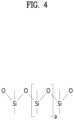
- FIG. 4 is a chemical structural formula showing a structure of a silicone-based adhesive layer applied to a transparent antenna according to an embodiment of the present disclosure.
- the silicone-based adhesive means a material including SiOH structure.
- a UV blocking film 150 may be disposed on the adhesive layer 110. That is, the UV blocking layer 150 may further be disposed between the adhesive layer 110 and the transparent substrate 20.
- the UV blocking function of the UV blocking film 150 means that 99% or more of UV light is blocked in a wavelength band of 330 to 380 nm.
- FIG. 5 is a chemical structural formula showing a structure of an acrylic adhesive layer applied to a transparent antenna according to an embodiment of the present disclosure.
- the adhesive layer 110 may include an acrylic material.
- the acrylic material refers to a material containing a combination of COOH and OH.
- An additive (sunscreen) capable of blocking UV rays may be mixed with the adhesive layer 110. Therefore, the adhesive layer 110 may act as an adhesive layer capable of blocking UV rays.
- the sunscreen may include at least one of a benzotriazole-based polymer, a triazole-based polymer, or an inorganic material including SiO2 (or TiO2).
- UV rays can be prevented from flowing into the transparent antenna 10 through a laminated structure of the adhesive layer 110 having strong UV light durability and the UV blocking film 150. Accordingly, the transparent antenna 10 can prevent the transparent antenna 10 from being damaged or yellowed due to UV rays.
- the transparent substrate 120 may include PET or Cyclo Olefin Polymer (COP).
- the transparent substrate 120 may have heat resistance.
- the transparent substrate 120 may use at least one of a heat-resistant PET material (dielectric constant of 3.0 to 3.2, dielectric loss of 0.005 to 0.01) and a COP (Cyclo Olefin Polymer) material having excellent characteristics in low dielectric and transparency.
- the COP material has a dielectric constant of 2.6 or less and a dielectric loss of 0.001 or less, which is lower than that of PET, so that low signal loss can be expected.
- the transparent antenna 10, which uses the transparent substrate 120 including the COP material due to high heat resistance (Tg ⁇ 170°C), may have high heat resistance.
- the transparent substrate 120 may require an appropriate thickness.
- the transparent substrate 120 may serve as a substrate having a low loss (low dielectric material) at a predetermined thickness (50 mm) or more. However, if the transparent substrate 10 becomes too thick, the flexibility of the transparent substrate 10 is degraded, so that it is not easy for the transparent substrate 10 to be bonded to the vehicle glass 20 having a curvature. In consideration of this situation, according to an embodiment of the present disclosure, the transparent substrate 120 may have a thickness of 50 to 150 ⁇ m.
- the heat-resistant cover layer 140 may include PET or Cyclo Olefin Polymer (COP).
- COP Cyclo Olefin Polymer
- the heat-resistant cover layer 140 may have the same physical properties as the transparent substrate 120. Therefore, redundant descriptions will herein be omitted for brevity.
- the antenna structure layer 130 disposed on the transparent substrate 120 may use a transparent electrode or a metal mesh as an antenna structure.
- the transparent electrode can be used in various ways, such as ITO (Indium Tin Oxide), CNT (Carbon Nanotube), nano-silverwire, metal mesh, etc.
- ITO Indium Tin Oxide
- CNT Carbon Nanotube
- nano-silverwire metal mesh
- metal mesh having low resistance and relatively low cost may be used to minimize signal loss.
- the antenna structure layer 130 may have a metal mesh shape.
- the antenna structure layer 130 may include a metal mesh structure 131 and a resin layer 132 filling the metal mesh structure 131.
- the metal mesh structure 131 may have a mesh structure in which metal lines having a first line width are spaced apart from each other by a first spacing.
- the power feeding portions 200 and 201 may be connected between the antenna structure layer 130 and the connection cables 300 and 301.
- first surfaces of the power feeding portions 200 and 201 may be connected to the antenna structure layer 130, and second surfaces of the power feeding portions 200 and 201 may be connected to the connection cables 300 and 301, respectively.
- connection portion 160 disposed on the antenna structure layer 130 and the bonding portion 210 disposed on the second surface of the power feeding portions 200 and 201 may be electrically connected by a solder 170 or the like.
- the bonding portion 220 disposed on the first surfaces of the power feeding portions 200 and 201 may be electrically connected to the connection cables 300 and 301 by the solder 171, etc.
- the power feeding portions 200 and 201 may include a substrate 230, a first metal layer 240 disposed on the first surface of the substrate 230, and a second metal layer 241 disposed on the second surface of the substrate 230.
- the power feeding portions 200 and 201 may be disposed on the black mask layer 180 located on the glass 20.
- a first cover layer 250 may be disposed on the first surfaces of the power feeding portions 200 and 201.
- a second cover layer 251 may be disposed on the second surfaces of the power feeding portions 200 and 201.
- At least one of the first cover layer 250 and the second cover layer 251 may include PET or Cyclo Olefin Polymer (COP).
- COP Cyclo Olefin Polymer
- at least one of the first cover layer 250 and the second cover layer 251 may have the same physical properties as the heat-resistant cover layer 140 or the transparent substrate 120. Therefore, redundant descriptions will herein be omitted.
- FIG. 6 is a diagram illustrating a metal mesh structure of a transparent antenna according to an embodiment of the present disclosure.
- FIG. 6 shows a photograph of the actually manufactured transparent antenna 10. A portion of the metal mesh structure 131 of the transparent antenna 10 is enlarged as shown in the right figure of FIG. 6 .
- the metal mesh structure 131 may be electrically connected to the power feeding portions 200 and 201.
- the thickness of the line constituting the metal mesh structure 131 may be referred to as a line width (critical dimension CD), and a line-to-line distance may be defined as a pitch.
- the line width of the metal mesh structure 131 may be set in consideration of resistance and transmittance thereof.
- FIG. 7 is a graph illustrating sheet resistance according to a line width (critical dimension CD) of the metal mesh structure.
- FIG. 8 is a graph illustrating transmittance according to a line width (critical dimension CD) of the metal mesh structure.
- the line width of the metal mesh structure is 2 to 8 mm in consideration of the antenna radiation characteristics and transmittance.
- the spacing between the metal mesh structures 131 becomes smaller, the resistance decreases and the antenna radiation characteristics are improved.
- the spacing between the metal mesh structures 131 becomes less than 50 nm, transmittance decreases so that the antenna structure becomes visible as a whole. Considering this situation, it is advantageous that the spacing between the metal mesh structures is 50 to 300 mm.
- a resin layer 132 made of resin or OCA (optical clear adhesive) material is positioned next to the metal mesh structure 131 so that the metal mesh structure 131 can be filled with the resin layer 132.
- the resin layer 132 can allow the metal mesh structure 131 to be mechanically stabilized.
- the occurrence of scratches on the transparent antenna 10 or damage to the transparent antenna 10 can be minimized by stacking the heat-resistant cover layer 140 on the uppermost layer of the transparent antenna 10.
- the transparent antenna 10 having the above structure can be applied as a transparent antenna for vehicles, can minimize signal loss, and can have high heat resistance. In addition, it is possible to implement a transparent antenna 10 capable of preventing yellowing caused by UV rays.
- 5G signals may have high straightness and are likely to lead to signal loss when there are obstacles.
- materials with low dielectric constant and dielectric loss are required (signal loss ⁇ frequency ⁇ dielectric constant 1/2 ⁇ dielectric loss).
- vehicle antennas have various requirements, such as antenna performance including signal loss, network scalability that can support future highspeed communication, design flexibility that does not damage the vehicle's unique design, ease of installation that can be installed in actual vehicles, and the like. Accordingly, vehicle antennas are being developed in various ways, such as shark fin antennas, dashboard-embedded types, spoiler-embedded types, and side-mirror types, in consideration of performance, design, and network scalability.
- the shark fin antennas which are most widely applied as vehicle antennas, have high transmission/reception (Tx/Rx) performance by being installed on the roof of vehicles, but have limitations in network scalability due to space restrictions.
- dashboard-embedded antenna is installed inside the vehicle and has poor antenna performance, but has an advantage of increasing network scalability due to relatively small spatial restrictions.
- the spoiler-embedded antenna and the sidemirror-embedded antenna have recently been developed and applied to vehicles to further increase the antenna performance and the network scalability, but such embedded-type antennas have difficulty in actual implementation in vehicles due to their design constraints.
- the transparent antenna for vehicle glass proposed in the present disclosure can be used as an antenna for FM/AM and LTE (4G) communication, and can be extended to 5G Sub6 and V2X communication supporting high frequencies.
- the transparent antenna according to the embodiment of the present disclosure can be used as a future antenna with network expandability without damaging the design of the vehicle.
- the transparent antenna according to the embodiment of the present disclosure has no design limitation, and thus can be applied to any vehicle.
- the transparent antenna according to the embodiment of the present disclosure can freely design and control the size and structure of the antenna and can be extended to 5G and V2X communication antennas.
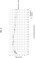
- FIG. 9 is a graph illustrating signal loss for each frequency of the transparent antenna according to an embodiment of the present disclosure.
- FIG. 9 signal loss of the transparent antenna 10 for each communication frequency is shown.
- square dots may represent actual measurement results, and circular dots may represent simulation results.
- FIG. 9 is a graph illustrating the result of the transparent antenna 10 showing a relatively small signal loss in actual measurement or simulation. This means that the transparent antenna 10 for vehicles according to an embodiment of the present disclosure can be actually used.
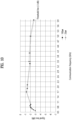
- FIG. 10 is a graph illustrating signal loss for each cover layer thickness of a transparent antenna according to an embodiment of the present disclosure.
- the heat-resistant cover layer 140 may be formed of heat-resistant PET or COP.
- the cover layer 140 may serve as a protective layer at a certain thickness 20 ⁇ m or more. However, if the cover layer 140 becomes too thick, signal loss may easily occur in the cover layer 140.
- the thickness range of the cover layer 140 may be 20 to 100 ⁇ m in consideration of these matters.
- FIG. 10 shows simulation values of signal loss in the 5G Sub6 band of the transparent antenna 10 for each thickness of the heat-resistant cover layer 140. That is, referring to FIG. 10 , simulation values of signal loss when the thickness of the heat resistant cover layer 140 is 100 ⁇ m and when the thickness is 23 ⁇ m are shown.
- the signal loss per frequency is not a problem within the acceptance criteria (-3 dBi).
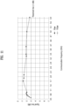
- FIG. 11 is a graph showing signal loss for each thickness of a transparent substrate of the transparent antenna according to an embodiment of the present disclosure.
- the heat-resistant transparent substrate 120 may be formed of heat-resistant PET or COP.
- the transparent substrate 120 may serve as a low-loss substrate at a certain thickness (50 ⁇ m) or more. However, if the transparent substrate 10 becomes too thick, the flexibility of the transparent substrate 10 is degraded, so that it is not easy for the transparent substrate 10 to be bonded to the vehicle glass 20 having a curvature.
- the thickness range of the transparent substrate 120 may be 50 to 150 ⁇ m in consideration of these matters.
- FIG. 11 shows simulation values of signal loss in the 5G Sub6 band of the transparent antenna 10 for each thickness of the transparent substrate 120. That is, referring to FIG. 11 , simulation values of signal loss when the thickness of the transparent substrate 120 is 50 ⁇ m and when the thickness is 150 ⁇ m are shown.
- the signal loss per frequency is not a problem within the acceptance criteria (-3 dBi).
- FIG. 12 is a graph illustrating signal loss for each thickness of the UV blocking film of the transparent antenna according to an embodiment of the present disclosure.
- the UV blocking film 150 and the adhesive layer 110 require a certain thickness (20 ⁇ m) or more to perform the role of UV blocking and adhesion. However, when the UV blocking film 150 and the adhesive layer 110 becomes too thick, an adhesive hardening phenomenon may occur to result in cracks.
- the thickness range of at least one of the UV blocking film 150 and the adhesive layer 110 may be 20 to 100 ⁇ m in consideration of these matters.
- FIG. 12 shows simulation values of signal loss in the 5G Sub6 band of the transparent antenna 10 for each thickness of the transparent substrate 120. That is, referring to FIG. 12 , simulation values of signal loss when the thickness of the UV blocking film 150 and the adhesive layer 110 is 20 ⁇ m, when the thickness of the UV blocking film 150 and the adhesive layer 110 is 50 ⁇ m, when the thickness of the UV blocking film 150 and the adhesive layer 110 is 70 ⁇ m, and when the thickness is 100 ⁇ m are shown.
- the signal loss per frequency is not a problem within the acceptance criteria (-3 dBi).
- the transparent antenna according to the embodiments of the present disclosure has the following effects.
- a transparent antenna for vehicles which can be applied to 5G communication and V2X communication, can be provided.
- the transparent antenna according to the embodiments of the present disclosure can implement low signal loss, high heat resistance, and yellowing prevention, which are suitable for the automotive environments.
- the transparent antenna according to the embodiment of the present disclosure can be freely installed in any vehicle design without damaging the original design of vehicles.
Landscapes
- Chemical & Material Sciences (AREA)
- Organic Chemistry (AREA)
- Engineering & Computer Science (AREA)
- Remote Sensing (AREA)
- Chemical Kinetics & Catalysis (AREA)
- Inorganic Chemistry (AREA)
- Details Of Aerials (AREA)
- Support Of Aerials (AREA)
Abstract
Description
- This application claims the benefit of an earlier filing date and right of priority to
Korean Application No. 10-2022-0020696, filed on February 17, 2022 - The embodiments of the present disclosure are applicable to antennas capable of supporting high frequencies, and more particularly to, for example, a transparent antenna applicable to glass for vehicles.
- As 5G communication has rapidly come into widespread use, the improvement process for automotive antennas (hereinafter referred to as vehicle antennas) is underway to expand from the existing FM/AM and LTE (4G) communication antennas to 5G Sub6 and V2X communication that supports high frequencies. Accordingly, vehicle antennas are being developed in various ways, such as a shark-fin antenna, a dashboard-embedded type, a spoiler-embedded type, and a side-mirror type, in consideration of performance, design, and network scalability.
- The shark fin antennas, which are most widely applied as vehicle antennas, have high transmission/reception (Tx/Rx) performance by being installed on the roof of vehicles, but have limitations in network scalability due to space restrictions.
- In contrast, the dashboard-embedded antenna is installed inside the vehicle and has poor antenna performance, but has an advantage of increasing network scalability due to relatively small spatial restrictions.
- In order to supplement these existing antennas, the spoiler-embedded antenna and the sidemirror-embedded antenna have recently been developed and applied to vehicles to further increase the antenna performance and the network scalability, but such embedded-type antennas have difficulty in actual implementation in vehicles due to their design constraints.
- Therefore, evolved antennas for vehicles, which can satisfy these various requirements, need to be developed.
- Accordingly, embodiments of the present disclosure are directed to a transparent antenna that substantially obviates one or more problems due to limitations and disadvantages of the related art. An object of the present disclosure is to provide a transparent antenna for vehicles applicable to 5G communication and V2X communication.
- Another object of the present disclosure is to provide a transparent antenna capable of implementing low signal loss, high heat resistance, and yellowing prevention that are suitable for automotive environments.
- Still another object of the present disclosure is to provide a transparent antenna that can be freely installed in any vehicle design without damaging the original design of vehicles.
- Technical tasks obtainable from the present disclosure are non-limited by the above-mentioned technical tasks. And, other unmentioned technical tasks can be clearly understood from the following description by those having ordinary skill in the technical field to which the present disclosure pertains.
- Additional advantages, objects, and features of the disclosure will be set forth in the disclosure herein as well as the accompanying drawings. Such aspects may also be appreciated by those skilled in the art based on the disclosure herein.
- To achieve these objects and other advantages and in accordance with the purpose of the disclosure, as embodied and broadly described herein, a transparent antenna may include: an adhesive layer attached to a glass; a transparent substrate disposed on the adhesive layer; an antenna structure layer disposed on the transparent substrate; a protective layer disposed on the antenna structure layer; and a power feeding portion connected to the antenna structure layer.
- The transparent antenna may further include a connection cable connected to the power feeding portion.
- A first surface of the power feeding portion may be connected to the antenna structure layer, and a second surface of the power feeding portion may be connected to the connection cable.
- The power feeding portion may include a substrate, a first metal layer disposed on a first surface of the substrate, and a second metal layer disposed on a second surface of the substrate.
- The power feeding portion may be disposed on a black mask layer located on the glass.
- The antenna structure layer may be formed in a metal mesh shape.
- The antenna structure layer may include a metal mesh structure, and a resin layer formed to fill the metal mesh structure.
- The metal mesh structure may be configured in a manner that metal lines having a first line width are spaced apart from each other by a first spacing to form the mesh structure.
- The transparent antenna may further include an ultraviolet (UV) blocking film disposed between the adhesive layer and the transparent substrate.
- The adhesive layer may include a silicone-based or acrylic material.
- The adhesive layer may include an ultraviolet (UV) blocking agent.
- The UV blocking agent may include at least one of a benzotriazole-based polymer, a triazole-based polymer, or an inorganic material including SiO2 (or TiO2).
- The transparent substrate may include PET or Cyclo Olefin Polymer (COP).
- In accordance with another aspect of the present disclosure, a transparent antenna may include: an adhesive layer attached to a glass of a vehicle; a transparent substrate disposed on the adhesive layer; an antenna structure layer disposed on the transparent substrate and having a metal mesh structure; a protective layer disposed on the antenna structure layer; and a power feeding portion connected to the antenna structure layer.
- The transparent antenna may further include a cover layer disposed on both sides of the power feeding portion.
- At least one of the cover layer and the transparent substrate may include PET or cyclo olefin imide polymer (COP).
- It is to be understood that both the foregoing general description and the following detailed description of the present disclosure are exemplary and explanatory and are intended to provide further explanation of the disclosure as claimed.
- The accompanying drawings, which are included to provide a further understanding of the disclosure and are incorporated in and constitute a part of this application, illustrate embodiment(s) of the disclosure and together with the description serve to explain the principle of the disclosure.
-
FIG. 1 is an exploded perspective view illustrating a transparent antenna according to an embodiment of the present disclosure. -
FIG. 2 is a cross-sectional view illustrating the principal constituent elements of a transparent antenna according to an embodiment of the present disclosure. -
FIG. 3 is a cross-sectional view illustrating a transparent antenna according to an embodiment of the present disclosure. -
FIG. 4 is a chemical structural formula illustrating a structure of a silicone-based adhesive layer applied to a transparent antenna according to an embodiment of the present disclosure. -
FIG. 5 is a chemical structural formula illustrating a structure of an acrylic adhesive layer applied to a transparent antenna according to an embodiment of the present disclosure. -
FIG. 6 is a diagram illustrating a metal mesh structure of a transparent antenna according to an embodiment of the present disclosure. -
FIG. 7 is a graph illustrating sheet resistance according to a line width (critical dimension CD) of a metal mesh structure. -
FIG. 8 is a graph illustrating transmittance according to a line width (critical dimension CD) of a metal mesh structure. -
FIG. 9 is a graph illustrating signal loss for each frequency of a transparent antenna according to an embodiment of the present disclosure. -
FIG. 10 is a graph illustrating signal loss for each cover layer thickness of a transparent antenna according to an embodiment of the present disclosure. -
FIG. 11 is a graph illustrating signal loss for each transparent substrate thickness of the transparent antenna according to an embodiment of the present disclosure. -
FIG. 12 is a graph illustrating signal loss for each thickness of an ultraviolet (UV) blocking film of a transparent antenna according to an embodiment of the present disclosure. - Reference will now be made in detail to embodiments of the present disclosure, examples of which are illustrated in the accompanying drawings. Wherever possible, the same reference numbers will be used throughout the drawings to refer to the same or like parts, and redundant description thereof will be omitted. As used herein, the suffixes "module" and "unit" are added or used interchangeably to facilitate preparation of this specification and are not intended to suggest distinct meanings or functions.
- In describing embodiments disclosed in this specification, relevant well-known technologies may not be described in detail in order not to obscure the subject matter of the embodiments disclosed in this specification. In addition, it should be noted that the accompanying drawings are only for easy understanding of the embodiments disclosed in the present specification, and should not be construed as limiting the technical spirit disclosed in the present specification.
- Furthermore, although the drawings are separately described for simplicity, embodiments implemented by combining at least two or more drawings are also within the scope of the present disclosure.
- In addition, when an element such as a layer, region or module is described as being "on" another element, it is to be understood that the element may be directly on the other element or there may be an intermediate element between them.
-
FIG. 1 is an exploded perspective view illustrating atransparent antenna 10 according to an embodiment of the present disclosure. - Referring to
FIG. 1 , atransparent antenna 10 according to an embodiment of the present disclosure may be attached to and installed on aglass 20. For example, thetransparent antenna 10 may be attached to and installed on a glass of a vehicle. The glass of such a vehicle may include a front glass (windshield), a rear glass, a sunroof glass, and the like. That is, thetransparent antenna 10 according to an embodiment of the present disclosure may be installed on a transparent glass installed in a vehicle. - The
transparent antenna 10 may broadly include anantenna portion 100 including anantenna structure layer 130 andpower feeding portions antenna structure layer 130. Thepower feeding portions transparent antenna 10 throughcables power feeding portion 200 may be connected to the device through thecable 300, and thepower feeding portion 201 may be connected to the device through thecable 301. In this case, thepower feeding portions antenna structure layer 130, respectively. That is, each of the two feedingportions bonding portion 210, and the twobonding portions 210 may be respectively connected to twoconnection portions 160 electrically connected to theantenna structure layer 130. - The
antenna structure layer 130 may include a conductive network structure such as a transparent electrode line or a metal mesh. This conductive network structure may be electrically connected to theconnection portion 160. Theconnection portion 160 is connected to thebonding portion 210 so that the conductive network structure of theantenna structure layer 130 may be electrically connected to thepower feeding portions - According to an embodiment of the present disclosure, the
antenna structure layer 130 may have a metal mesh structure as a conductive network structure. This will be described later in detail. - The
cables cables power feeding portions - A
black mask layer 180 may be provided on the surface of theglass 20. The edges of theglass 20 of the vehicle can usually be treated with a black mask. That is, theblack mask layer 180 may be located at the edges of the vehicle glass. Aconnector 310 of theFakra cables black mask layer 180 is located. Also, thetransparent antenna 10 may be located inside the black mask layer 180 (upper side inFIG. 1 ). - The
power feeding portions transparent antenna 10 to theconnector 310 of theFakra cables black mask layer 180 or on the surface of theglass 20 as needed. - The
transparent antenna 10 may be protected by a heat-resistant cover layer 140 (seeFIG. 2 ). The heat-resistant cover layer 140 will be described later in detail. - Through the structure of the
transparent antenna 10, thetransparent antenna 10 is located not to be seen from the outside so that the driver's FOV (field of view) is not disturbed at all without damaging the original design of the vehicle. In addition, since thetransparent antenna 10 can be attached to and installed on thevehicle glass 20, thetransparent antenna 10 has an advantage of being easy to install on thevehicle glass 20. -
FIG. 2 is a cross-sectional view illustrating the principal constituent elements of a transparent antenna according to an embodiment of the present disclosure.FIG. 3 is a cross-sectional view illustrating a transparent antenna according to an embodiment of the present disclosure. - Referring to
FIG. 2 , anantenna portion 100 of thetransparent antenna 10 may include anadhesive layer 110 attached to theglass 20, atransparent substrate 120 disposed on theadhesive layer 110, and anantenna structure layer 130 disposed on thetransparent substrate 120. A heat-resistant cover layer 140 may be located on theantenna structure layer 130. - In
FIG. 2 , the direction of the arrow C may represent the inward direction of the vehicle. That is, when thetransparent antenna 10 is installed on thevehicle glass 20, theadhesive layer 110 may be attached to the inner surface of thevehicle glass 20 so that thetransparent antenna 10 can be installed on thevehicle glass 20. - The
adhesive layer 110 may include a silicone-based or acrylic material. For example, theadhesive layer 110 may use an acrylic or silicone-based material having excellent durability against ultraviolet (UV) light. -
FIG. 4 is a chemical structural formula showing a structure of a silicone-based adhesive layer applied to a transparent antenna according to an embodiment of the present disclosure. - Referring to
FIG. 4 , the silicone-based adhesive means a material including SiOH structure. - A
UV blocking film 150 may be disposed on theadhesive layer 110. That is, theUV blocking layer 150 may further be disposed between theadhesive layer 110 and thetransparent substrate 20. - The UV blocking function of the
UV blocking film 150 means that 99% or more of UV light is blocked in a wavelength band of 330 to 380 nm. -
FIG. 5 is a chemical structural formula showing a structure of an acrylic adhesive layer applied to a transparent antenna according to an embodiment of the present disclosure. - In an exemplary embodiment, the
adhesive layer 110 may include an acrylic material. - As shown in
FIG. 5 , the acrylic material refers to a material containing a combination of COOH and OH. An additive (sunscreen) capable of blocking UV rays may be mixed with theadhesive layer 110. Therefore, theadhesive layer 110 may act as an adhesive layer capable of blocking UV rays. - In an exemplary embodiment, the sunscreen may include at least one of a benzotriazole-based polymer, a triazole-based polymer, or an inorganic material including SiO2 (or TiO2).
- UV rays can be prevented from flowing into the
transparent antenna 10 through a laminated structure of theadhesive layer 110 having strong UV light durability and theUV blocking film 150. Accordingly, thetransparent antenna 10 can prevent thetransparent antenna 10 from being damaged or yellowed due to UV rays. - The
transparent substrate 120 may include PET or Cyclo Olefin Polymer (COP). Thetransparent substrate 120 may have heat resistance. For example, thetransparent substrate 120 may use at least one of a heat-resistant PET material (dielectric constant of 3.0 to 3.2, dielectric loss of 0.005 to 0.01) and a COP (Cyclo Olefin Polymer) material having excellent characteristics in low dielectric and transparency. The COP material has a dielectric constant of 2.6 or less and a dielectric loss of 0.001 or less, which is lower than that of PET, so that low signal loss can be expected. Thetransparent antenna 10, which uses thetransparent substrate 120 including the COP material due to high heat resistance (Tg ~170°C), may have high heat resistance. Thetransparent substrate 120 may require an appropriate thickness. Thetransparent substrate 120 may serve as a substrate having a low loss (low dielectric material) at a predetermined thickness (50 mm) or more. However, if thetransparent substrate 10 becomes too thick, the flexibility of thetransparent substrate 10 is degraded, so that it is not easy for thetransparent substrate 10 to be bonded to thevehicle glass 20 having a curvature. In consideration of this situation, according to an embodiment of the present disclosure, thetransparent substrate 120 may have a thickness of 50 to 150 µm. - Meanwhile, the heat-
resistant cover layer 140 may include PET or Cyclo Olefin Polymer (COP). For example, the heat-resistant cover layer 140 may have the same physical properties as thetransparent substrate 120. Therefore, redundant descriptions will herein be omitted for brevity. - The
antenna structure layer 130 disposed on thetransparent substrate 120 may use a transparent electrode or a metal mesh as an antenna structure. - As the transparent electrode can be used in various ways, such as ITO (Indium Tin Oxide), CNT (Carbon Nanotube), nano-silverwire, metal mesh, etc. According to an embodiment of the present disclosure, a metal mesh having low resistance and relatively low cost may be used to minimize signal loss.
- That is, as an exemplary embodiment, the
antenna structure layer 130 may have a metal mesh shape. Referring toFIGS. 2 and3 , theantenna structure layer 130 may include ametal mesh structure 131 and aresin layer 132 filling themetal mesh structure 131. - The
metal mesh structure 131 may have a mesh structure in which metal lines having a first line width are spaced apart from each other by a first spacing. - The
power feeding portions antenna structure layer 130 and theconnection cables - In an exemplary embodiment, first surfaces of the
power feeding portions antenna structure layer 130, and second surfaces of thepower feeding portions connection cables - As described above, the
connection portion 160 disposed on theantenna structure layer 130 and thebonding portion 210 disposed on the second surface of thepower feeding portions solder 170 or the like. - In addition, the
bonding portion 220 disposed on the first surfaces of thepower feeding portions connection cables solder 171, etc. - The
power feeding portions substrate 230, afirst metal layer 240 disposed on the first surface of thesubstrate 230, and asecond metal layer 241 disposed on the second surface of thesubstrate 230. - The
power feeding portions black mask layer 180 located on theglass 20. - A
first cover layer 250 may be disposed on the first surfaces of thepower feeding portions second cover layer 251 may be disposed on the second surfaces of thepower feeding portions - At least one of the
first cover layer 250 and thesecond cover layer 251 may include PET or Cyclo Olefin Polymer (COP). For example, at least one of thefirst cover layer 250 and thesecond cover layer 251 may have the same physical properties as the heat-resistant cover layer 140 or thetransparent substrate 120. Therefore, redundant descriptions will herein be omitted. -
FIG. 6 is a diagram illustrating a metal mesh structure of a transparent antenna according to an embodiment of the present disclosure. -
FIG. 6 shows a photograph of the actually manufacturedtransparent antenna 10. A portion of themetal mesh structure 131 of thetransparent antenna 10 is enlarged as shown in the right figure ofFIG. 6 . Themetal mesh structure 131 may be electrically connected to thepower feeding portions - At this time, the thickness of the line constituting the
metal mesh structure 131 may be referred to as a line width (critical dimension CD), and a line-to-line distance may be defined as a pitch. - In general, when the line width of the
metal mesh structure 131 is increased, resistance of themetal mesh structure 131 decreases and antenna radiation characteristics of themetal mesh structure 131 can be improved. On the other hand, when the line width becomes thicker than a certain thickness, transmittance decreases and the antenna line becomes visible. - Accordingly, the line width of the
metal mesh structure 131 may be set in consideration of resistance and transmittance thereof. -
FIG. 7 is a graph illustrating sheet resistance according to a line width (critical dimension CD) of the metal mesh structure.FIG. 8 is a graph illustrating transmittance according to a line width (critical dimension CD) of the metal mesh structure. - As described above, referring to
FIG. 7 , sheet resistance decreases as the line width increases. This means that the antenna radiation performance is improved. Conversely, referring toFIG. 8 , as the line width increases, transmittance decreases. This means that thetransparent antenna 10 can be seen in the driver's field of view. According to an embodiment of the present disclosure, it is advantageous that the line width of the metal mesh structure is 2 to 8 mm in consideration of the antenna radiation characteristics and transmittance. - On the other hand, if the spacing between the
metal mesh structures 131 becomes smaller, the resistance decreases and the antenna radiation characteristics are improved. However, when the spacing between themetal mesh structures 131 becomes less than 50 nm, transmittance decreases so that the antenna structure becomes visible as a whole. Considering this situation, it is advantageous that the spacing between the metal mesh structures is 50 to 300 mm. - When the
metal mesh structure 131 exists alone, mechanical durability may be deteriorated. Therefore, aresin layer 132 made of resin or OCA (optical clear adhesive) material is positioned next to themetal mesh structure 131 so that themetal mesh structure 131 can be filled with theresin layer 132. - As such, the
resin layer 132 can allow themetal mesh structure 131 to be mechanically stabilized. In addition, as described above, the occurrence of scratches on thetransparent antenna 10 or damage to thetransparent antenna 10 can be minimized by stacking the heat-resistant cover layer 140 on the uppermost layer of thetransparent antenna 10. - The
transparent antenna 10 having the above structure can be applied as a transparent antenna for vehicles, can minimize signal loss, and can have high heat resistance. In addition, it is possible to implement atransparent antenna 10 capable of preventing yellowing caused by UV rays. - As 5G communication has rapidly come into widespread use, the improvement process for vehicle antennas is underway to expand from the existing FM/AM and LTE (4G) communication antennas to 5G Sub6 and V2X communication that supports high frequencies.
- However, as the frequency increases, 5G signals may have high straightness and are likely to lead to signal loss when there are obstacles. In order to minimize signal loss in the 5G band, materials with low dielectric constant and dielectric loss are required (signal loss ∝ frequency × dielectric constant 1/2 × dielectric loss).
- In particular, vehicle antennas have various requirements, such as antenna performance including signal loss, network scalability that can support future highspeed communication, design flexibility that does not damage the vehicle's unique design, ease of installation that can be installed in actual vehicles, and the like. Accordingly, vehicle antennas are being developed in various ways, such as shark fin antennas, dashboard-embedded types, spoiler-embedded types, and side-mirror types, in consideration of performance, design, and network scalability.
- The shark fin antennas, which are most widely applied as vehicle antennas, have high transmission/reception (Tx/Rx) performance by being installed on the roof of vehicles, but have limitations in network scalability due to space restrictions.
- In contrast, the dashboard-embedded antenna is installed inside the vehicle and has poor antenna performance, but has an advantage of increasing network scalability due to relatively small spatial restrictions.
- In order to supplement these existing antennas, the spoiler-embedded antenna and the sidemirror-embedded antenna have recently been developed and applied to vehicles to further increase the antenna performance and the network scalability, but such embedded-type antennas have difficulty in actual implementation in vehicles due to their design constraints.
- The transparent antenna for vehicle glass proposed in the present disclosure can be used as an antenna for FM/AM and LTE (4G) communication, and can be extended to 5G Sub6 and V2X communication supporting high frequencies.
- In addition, the transparent antenna according to the embodiment of the present disclosure can be used as a future antenna with network expandability without damaging the design of the vehicle.
- In addition, the transparent antenna according to the embodiment of the present disclosure has no design limitation, and thus can be applied to any vehicle.
- In addition, the transparent antenna according to the embodiment of the present disclosure can freely design and control the size and structure of the antenna and can be extended to 5G and V2X communication antennas.
- Hereinafter, antenna performance measured in the 5G sub6 band (< 6 GHz) by bonding a transparent antenna having the above-described structure to glass will be described in detail.
-
FIG. 9 is a graph illustrating signal loss for each frequency of the transparent antenna according to an embodiment of the present disclosure. - Referring to
FIG. 9 , signal loss of thetransparent antenna 10 for each communication frequency is shown. InFIG. 9 , square dots may represent actual measurement results, and circular dots may represent simulation results. - As shown in
FIG. 9 , it can be confirmed that the actual measurement and simulation results are almost similar to each other. This means that the antenna structure can be predicted to some extent through simulation. Considering that a threshold line (reference line) of signal loss of the communication device is generally considered to be -3 dBi,FIG. 9 is a graph illustrating the result of thetransparent antenna 10 showing a relatively small signal loss in actual measurement or simulation. This means that thetransparent antenna 10 for vehicles according to an embodiment of the present disclosure can be actually used. -
FIG. 10 is a graph illustrating signal loss for each cover layer thickness of a transparent antenna according to an embodiment of the present disclosure. - As described above, according to an embodiment of the present disclosure, the heat-
resistant cover layer 140 may be formed of heat-resistant PET or COP. - The
cover layer 140 may serve as a protective layer at acertain thickness 20 µm or more. However, if thecover layer 140 becomes too thick, signal loss may easily occur in thecover layer 140. - According to an embodiment of the present disclosure, the thickness range of the
cover layer 140 may be 20 to 100 µm in consideration of these matters. -
FIG. 10 shows simulation values of signal loss in the 5G Sub6 band of thetransparent antenna 10 for each thickness of the heat-resistant cover layer 140. That is, referring toFIG. 10 , simulation values of signal loss when the thickness of the heatresistant cover layer 140 is 100 µm and when the thickness is 23 µm are shown. - In the range proposed by the present disclosure, it can be confirmed that the signal loss per frequency is not a problem within the acceptance criteria (-3 dBi).
-
FIG. 11 is a graph showing signal loss for each thickness of a transparent substrate of the transparent antenna according to an embodiment of the present disclosure. As described above, according to an embodiment of the present disclosure, the heat-resistanttransparent substrate 120 may be formed of heat-resistant PET or COP. Thetransparent substrate 120 may serve as a low-loss substrate at a certain thickness (50 µm) or more. However, if thetransparent substrate 10 becomes too thick, the flexibility of thetransparent substrate 10 is degraded, so that it is not easy for thetransparent substrate 10 to be bonded to thevehicle glass 20 having a curvature. - According to an embodiment of the present disclosure, the thickness range of the
transparent substrate 120 may be 50 to 150 µm in consideration of these matters. -
FIG. 11 shows simulation values of signal loss in the 5G Sub6 band of thetransparent antenna 10 for each thickness of thetransparent substrate 120. That is, referring toFIG. 11 , simulation values of signal loss when the thickness of thetransparent substrate 120 is 50 µm and when the thickness is 150 µm are shown. - In the range proposed by the present disclosure, it can be confirmed that the signal loss per frequency is not a problem within the acceptance criteria (-3 dBi).
-
FIG. 12 is a graph illustrating signal loss for each thickness of the UV blocking film of the transparent antenna according to an embodiment of the present disclosure. - The
UV blocking film 150 and theadhesive layer 110 require a certain thickness (20 µm) or more to perform the role of UV blocking and adhesion. However, when theUV blocking film 150 and theadhesive layer 110 becomes too thick, an adhesive hardening phenomenon may occur to result in cracks. - According to an embodiment of the present disclosure, the thickness range of at least one of the
UV blocking film 150 and theadhesive layer 110 may be 20 to 100 µm in consideration of these matters. -
FIG. 12 shows simulation values of signal loss in the 5G Sub6 band of thetransparent antenna 10 for each thickness of thetransparent substrate 120. That is, referring toFIG. 12 , simulation values of signal loss when the thickness of theUV blocking film 150 and theadhesive layer 110 is 20 µm, when the thickness of theUV blocking film 150 and theadhesive layer 110 is 50 µm, when the thickness of theUV blocking film 150 and theadhesive layer 110 is 70 µm, and when the thickness is 100 µm are shown. - In the range proposed by the present disclosure, it can be confirmed that the signal loss per frequency is not a problem within the acceptance criteria (-3 dBi).
- The above description is merely illustrative of the technical idea of the present disclosure. Those of ordinary skill in the art to which the present disclosure pertains will be able to make various modifications and variations without departing from the essential characteristics of the present disclosure.
- Therefore, embodiments disclosed in the present disclosure are not intended to limit the technical idea of the present disclosure, but to describe, and the scope of the technical idea of the present disclosure is not limited by such embodiments.
- The scope of protection of the present disclosure should be interpreted by the claims below, and all technical ideas within the scope equivalent thereto should be construed as being included in the scope of the present disclosure.
- According to the present disclosure, it is possible to provide a transparent antenna for vehicles applicable to 5G communication and V2X communication.
- As is apparent from the above description, the transparent antenna according to the embodiments of the present disclosure has the following effects.
- According to the embodiments of the present disclosure, a transparent antenna for vehicles, which can be applied to 5G communication and V2X communication, can be provided.
- The transparent antenna according to the embodiments of the present disclosure can implement low signal loss, high heat resistance, and yellowing prevention, which are suitable for the automotive environments.
- In addition, the transparent antenna according to the embodiment of the present disclosure can be freely installed in any vehicle design without damaging the original design of vehicles.
- Furthermore, according to another embodiment of the present disclosure, there are additional technical effects not mentioned herein. Those skilled in the art will appreciate such technical effects through the whole of the specification and drawings.
- It will be apparent to those skilled in the art that various modifications and variations can be made in the present disclosure without departing from the spirit or scope of the disclosures. Thus, it is intended that the present disclosure covers the modifications and variations of this disclosure provided they come within the scope of the appended claims and their equivalents.
Claims (20)
- A transparent antenna comprising:an adhesive layer configured to be attached to a mounting surface;a transparent substrate disposed on the adhesive layer;an antenna structure layer disposed on the transparent substrate;a protective layer disposed on the antenna structure layer; anda power feeding portion connected to the antenna structure layer.
- The transparent antenna according to claim 1, further comprising:
a connection cable connected to the power feeding portion. - The transparent antenna according to claim 1, wherein:a first surface of the power feeding portion is connected to the antenna structure layer; anda second surface of the power feeding portion is connected to the connection cable.
- The transparent antenna according to claim 1, wherein the power feeding portion includes:a substrate;a first metal layer disposed on a first surface of the substrate; anda second metal layer disposed on a second surface of the substrate.
- The transparent antenna according to claim 1, wherein:
the power feeding portion is configured to be disposed on a black mask layer of the mounting surface. - The transparent antenna according to claim 1, wherein:
the antenna structure layer is formed to have a metal mesh structure. - The transparent antenna according to claim 1, wherein the antenna structure layer comprises:a metal mesh structure; anda resin layer formed to fill the metal mesh structure.
- The transparent antenna according to claim 7, wherein:
the metal mesh structure comprises metal lines spaced apart from each other by a first spacing in the range of 2 to 8 mm. - The transparent antenna according to claim 1, further comprising:
an ultraviolet (UV) blocking film disposed between the adhesive layer and the transparent substrate. - The transparent antenna according to claim 1, wherein:
the adhesive layer includes a silicone-based or acrylic material. - The transparent antenna according to claim 1, wherein:
the adhesive layer includes an ultraviolet (UV) blocking agent. - The transparent antenna according to claim 11, wherein:
the UV blocking agent includes at least one of a benzotriazole-based polymer, a triazole-based polymer, or an inorganic material including SiO2 or TiO2. - The transparent antenna according to claim 11, wherein:
the transparent substrate includes PET or Cyclo Olefin Polymer (COP). - A transparent antenna comprising:an adhesive layer configured to be attached to glass of a vehicle;a transparent substrate disposed on the adhesive layer;an antenna structure layer disposed on the transparent substrate and having a metal mesh structure;a protective layer disposed on the antenna structure layer; anda power feeding portion connected to the antenna structure layer.
- The transparent antenna according to claim 14, further comprising:
a cover layer disposed on both sides of the power feeding portion. - The transparent antenna according to claim 15, wherein:
at least one of the cover layer or the transparent substrate includes PET or cyclo olefin imide polymer (COP). - The transparent antenna according to claim 14, wherein the power feeding portion includes:a substrate;a first metal layer disposed on a first surface of the substrate; anda second metal layer disposed on a second surface of the substrate.
- The transparent antenna according to claim 14, wherein the antenna structure layer further includes:
a resin formed to fill the metal mesh structure. - The transparent antenna according to claim 14, wherein,
the power feeding portion is configured to be disposed on a black mask layer of the glass. - The transparent antenna according to claim 14, further comprising:
an ultraviolet (UV) blocking film disposed between the adhesive layer and the transparent substrate.
Applications Claiming Priority (2)
| Application Number | Priority Date | Filing Date | Title |
|---|---|---|---|
| KR20220020696 | 2022-02-17 | ||
| PCT/KR2022/008676 WO2023158026A1 (en) | 2022-02-17 | 2022-06-20 | Transparent antenna |
Publications (2)
| Publication Number | Publication Date |
|---|---|
| EP4478532A1 true EP4478532A1 (en) | 2024-12-18 |
| EP4478532A4 EP4478532A4 (en) | 2025-05-14 |
Family
ID=87558083
Family Applications (1)
| Application Number | Title | Priority Date | Filing Date |
|---|---|---|---|
| EP22927424.6A Pending EP4478532A4 (en) | 2022-02-17 | 2022-06-20 | TRANSPARENT ANTENNA |
Country Status (4)
| Country | Link |
|---|---|
| US (1) | US12355146B2 (en) |
| EP (1) | EP4478532A4 (en) |
| KR (1) | KR20240151758A (en) |
| CN (1) | CN118743107A (en) |
Families Citing this family (2)
| Publication number | Priority date | Publication date | Assignee | Title |
|---|---|---|---|---|
| KR20240151758A (en) * | 2022-02-17 | 2024-10-18 | 엘지전자 주식회사 | transparent antenna |
| KR20240160659A (en) * | 2022-06-23 | 2024-11-11 | 엘지전자 주식회사 | Antenna module disposed in vehicle |
Family Cites Families (30)
| Publication number | Priority date | Publication date | Assignee | Title |
|---|---|---|---|---|
| US6384790B2 (en) * | 1998-06-15 | 2002-05-07 | Ppg Industries Ohio, Inc. | Antenna on-glass |
| KR20020022482A (en) | 2000-09-20 | 2002-03-27 | 이용재 | The plane shaped film antenna |
| EP1543581B1 (en) * | 2002-09-17 | 2011-07-20 | PILKINGTON Automotive Deutschland GmbH | Antenna pane |
| US7190316B2 (en) * | 2004-03-05 | 2007-03-13 | Delphi Techologies, Inc. | Vehicular glass-mount antenna and system |
| US7119751B2 (en) * | 2005-03-11 | 2006-10-10 | Agc Automotive Americas R&D, Inc. | Dual-layer planar antenna |
| US7656357B2 (en) * | 2005-04-01 | 2010-02-02 | Nissha Printing Co., Ltd. | Transparent antenna for vehicle and vehicle glass with antenna |
| GB0520303D0 (en) * | 2005-10-06 | 2005-11-16 | Pilkington Plc | Laminated glazing |
| KR20100124954A (en) | 2009-05-20 | 2010-11-30 | 엘지이노텍 주식회사 | Antenna of broadcasting signal receiver and method for manufacturing the same |
| KR101077044B1 (en) | 2009-06-23 | 2011-10-27 | 주식회사 에이스테크놀로지 | Communication device for a vehicle, room mirror structure included in the same and shade band connected electrically to the room mirro structrue |
| US8466842B2 (en) * | 2010-10-22 | 2013-06-18 | Pittsburgh Glass Works, Llc | Window antenna |
| JP2014045230A (en) * | 2010-12-28 | 2014-03-13 | Asahi Glass Co Ltd | Antenna device |
| US20170033433A1 (en) * | 2014-04-14 | 2017-02-02 | Shanghai Amphenol Airwave Communication Electronics Co., Ltd. | Windshield Antenna |
| KR102243381B1 (en) | 2014-11-07 | 2021-04-22 | 삼성전자주식회사 | Antenna device |
| CN106463812A (en) * | 2015-04-08 | 2017-02-22 | 法国圣戈班玻璃厂 | Windscreen antenna |
| US10205216B2 (en) * | 2016-05-06 | 2019-02-12 | GM Global Technology Operations LLC | Thin film antenna to FAKRA connector |
| JP6812825B2 (en) * | 2017-02-14 | 2021-01-13 | Agc株式会社 | Glass antennas and windowpanes for vehicles |
| EP3828994B1 (en) * | 2018-10-05 | 2024-07-31 | Agc Inc. | Antenna system |
| KR20200114886A (en) * | 2019-03-29 | 2020-10-07 | 동우 화인켐 주식회사 | Optically clear adhesive film and display device using the same |
| JP7511134B2 (en) * | 2019-05-16 | 2024-07-05 | Agc株式会社 | Planar antenna, antenna laminate, and vehicle window glass |
| EP4054844A4 (en) * | 2019-12-06 | 2023-05-17 | Pittsburgh Glass Works, LLC | MULTI-LAYER GLASS PLANAR ANTENNA |
| WO2021229994A1 (en) * | 2020-05-13 | 2021-11-18 | 富士フイルム株式会社 | Antenna |
| KR102552305B1 (en) * | 2020-10-29 | 2023-07-07 | 엘지전자 주식회사 | Broadband antennas deployed in vehicles |
| US12266851B2 (en) * | 2021-04-23 | 2025-04-01 | Beijing Boe Technology Development Co., Ltd. | Manufacturing method of metal mesh, thin film sensor and manufacturing method thereof |
| TWI818257B (en) * | 2021-05-07 | 2023-10-11 | 財團法人工業技術研究院 | Transparent antenna and manufacturing method thereof |
| US11637357B2 (en) * | 2021-08-24 | 2023-04-25 | GM Global Technology Operations LLC | Windshield embedded multiband GNSS transparent antenna with a multiband electromagnetic coupler |
| KR20240151758A (en) * | 2022-02-17 | 2024-10-18 | 엘지전자 주식회사 | transparent antenna |
| KR102875823B1 (en) * | 2022-03-15 | 2025-10-22 | 동우 화인켐 주식회사 | Antenna device |
| KR102801306B1 (en) * | 2022-07-05 | 2025-04-30 | 엘지전자 주식회사 | Antenna module placed on a vehicle |
| US12500334B2 (en) * | 2022-11-11 | 2025-12-16 | Lg Electronics Inc. | Transparent antenna module and method for manufacturing the same |
| EP4468513A1 (en) * | 2023-05-22 | 2024-11-27 | Volvo Car Corporation | Antenna for a glass roof of a vehicle |
-
2022
- 2022-06-20 KR KR1020247026712A patent/KR20240151758A/en active Pending
- 2022-06-20 CN CN202280091967.8A patent/CN118743107A/en active Pending
- 2022-06-20 EP EP22927424.6A patent/EP4478532A4/en active Pending
-
2023
- 2023-02-14 US US18/168,872 patent/US12355146B2/en active Active
Also Published As
| Publication number | Publication date |
|---|---|
| US20230261367A1 (en) | 2023-08-17 |
| KR20240151758A (en) | 2024-10-18 |
| EP4478532A4 (en) | 2025-05-14 |
| US12355146B2 (en) | 2025-07-08 |
| CN118743107A (en) | 2024-10-01 |
Similar Documents
| Publication | Publication Date | Title |
|---|---|---|
| US12355146B2 (en) | Transparent antenna | |
| JP7511134B2 (en) | Planar antenna, antenna laminate, and vehicle window glass | |
| US12034219B2 (en) | Transparent antenna stack and assembly | |
| CN103636060B (en) | For the strap Connection Element of antenna structure | |
| US20180316365A1 (en) | Multi-band radio frequency transparency window in conductive film | |
| JP4779059B2 (en) | Electromagnetic shielding panel, window member, structure, electromagnetic shielding room and electromagnetic shielding box | |
| US20240145931A1 (en) | Metamaterial structure, metamaterial-type transparent heater, and radar apparatus using metamaterial-type transparent heater | |
| CN107086366A (en) | Broadband coplanar wave guide feedback single-stage paster antenna | |
| CN116034055A (en) | Radome for vehicle radar device and structure of vehicle radar | |
| JP7212285B2 (en) | vehicle window glass | |
| US20160096346A1 (en) | Laminated glass for vehicle | |
| KR20210087933A (en) | Coaxial connector and board with coaxial connector | |
| US12490417B2 (en) | Ground structure-equipped laminated glass for vehicles | |
| JP2011172281A (en) | Component for forming vehicular glass antenna | |
| KR20250120257A (en) | Transparent antenna module and method for manufacturing the same | |
| JP4788333B2 (en) | Glass antenna for vehicles | |
| JP2024004452A (en) | vehicle window glass | |
| KR100730212B1 (en) | Filter assembly and plasma display device having same | |
| CN117691338A (en) | Multiband transparent coplanar slot antenna using conductive windshield coating | |
| US20220416399A1 (en) | Vehicle pane | |
| US20260039008A1 (en) | Feeding structure and window glass | |
| EP4601113A1 (en) | Transparent antenna module arranged on vehicle glass | |
| CN111341494A (en) | An optoelectronic composite cable | |
| WO2025173587A1 (en) | Antenna device for vehicle | |
| WO2025047480A1 (en) | Antenna device |
Legal Events
| Date | Code | Title | Description |
|---|---|---|---|
| STAA | Information on the status of an ep patent application or granted ep patent |
Free format text: STATUS: THE INTERNATIONAL PUBLICATION HAS BEEN MADE |
|
| PUAI | Public reference made under article 153(3) epc to a published international application that has entered the european phase |
Free format text: ORIGINAL CODE: 0009012 |
|
| STAA | Information on the status of an ep patent application or granted ep patent |
Free format text: STATUS: REQUEST FOR EXAMINATION WAS MADE |
|
| 17P | Request for examination filed |
Effective date: 20240911 |
|
| AK | Designated contracting states |
Kind code of ref document: A1 Designated state(s): AL AT BE BG CH CY CZ DE DK EE ES FI FR GB GR HR HU IE IS IT LI LT LU LV MC MK MT NL NO PL PT RO RS SE SI SK SM TR |
|
| A4 | Supplementary search report drawn up and despatched |
Effective date: 20250411 |
|
| RIC1 | Information provided on ipc code assigned before grant |
Ipc: H01Q 1/38 20060101ALI20250407BHEP Ipc: H01Q 1/12 20060101AFI20250407BHEP |
|
| DAV | Request for validation of the european patent (deleted) | ||
| DAX | Request for extension of the european patent (deleted) |