EP4478526A1 - Battery module, and battery pack and vehicle including same - Google Patents
Battery module, and battery pack and vehicle including same Download PDFInfo
- Publication number
- EP4478526A1 EP4478526A1 EP23921496.8A EP23921496A EP4478526A1 EP 4478526 A1 EP4478526 A1 EP 4478526A1 EP 23921496 A EP23921496 A EP 23921496A EP 4478526 A1 EP4478526 A1 EP 4478526A1
- Authority
- EP
- European Patent Office
- Prior art keywords
- battery module
- support
- terminal
- battery
- module according
- Prior art date
- Legal status (The legal status is an assumption and is not a legal conclusion. Google has not performed a legal analysis and makes no representation as to the accuracy of the status listed.)
- Pending
Links
Images




Classifications
-
- H—ELECTRICITY
- H01—ELECTRIC ELEMENTS
- H01M—PROCESSES OR MEANS, e.g. BATTERIES, FOR THE DIRECT CONVERSION OF CHEMICAL ENERGY INTO ELECTRICAL ENERGY
- H01M50/00—Constructional details or processes of manufacture of the non-active parts of electrochemical cells other than fuel cells, e.g. hybrid cells
- H01M50/50—Current conducting connections for cells or batteries
- H01M50/572—Means for preventing undesired use or discharge
- H01M50/584—Means for preventing undesired use or discharge for preventing incorrect connections inside or outside the batteries
- H01M50/588—Means for preventing undesired use or discharge for preventing incorrect connections inside or outside the batteries outside the batteries, e.g. incorrect connections of terminals or busbars
-
- H—ELECTRICITY
- H01—ELECTRIC ELEMENTS
- H01M—PROCESSES OR MEANS, e.g. BATTERIES, FOR THE DIRECT CONVERSION OF CHEMICAL ENERGY INTO ELECTRICAL ENERGY
- H01M10/00—Secondary cells; Manufacture thereof
- H01M10/60—Heating or cooling; Temperature control
- H01M10/65—Means for temperature control structurally associated with the cells
- H01M10/658—Means for temperature control structurally associated with the cells by thermal insulation or shielding
-
- H—ELECTRICITY
- H01—ELECTRIC ELEMENTS
- H01M—PROCESSES OR MEANS, e.g. BATTERIES, FOR THE DIRECT CONVERSION OF CHEMICAL ENERGY INTO ELECTRICAL ENERGY
- H01M50/00—Constructional details or processes of manufacture of the non-active parts of electrochemical cells other than fuel cells, e.g. hybrid cells
- H01M50/20—Mountings; Secondary casings or frames; Racks, modules or packs; Suspension devices; Shock absorbers; Transport or carrying devices; Holders
- H01M50/249—Mountings; Secondary casings or frames; Racks, modules or packs; Suspension devices; Shock absorbers; Transport or carrying devices; Holders specially adapted for aircraft or vehicles, e.g. cars or trains
-
- H—ELECTRICITY
- H01—ELECTRIC ELEMENTS
- H01M—PROCESSES OR MEANS, e.g. BATTERIES, FOR THE DIRECT CONVERSION OF CHEMICAL ENERGY INTO ELECTRICAL ENERGY
- H01M50/00—Constructional details or processes of manufacture of the non-active parts of electrochemical cells other than fuel cells, e.g. hybrid cells
- H01M50/20—Mountings; Secondary casings or frames; Racks, modules or packs; Suspension devices; Shock absorbers; Transport or carrying devices; Holders
- H01M50/262—Mountings; Secondary casings or frames; Racks, modules or packs; Suspension devices; Shock absorbers; Transport or carrying devices; Holders with fastening means, e.g. locks
-
- H—ELECTRICITY
- H01—ELECTRIC ELEMENTS
- H01M—PROCESSES OR MEANS, e.g. BATTERIES, FOR THE DIRECT CONVERSION OF CHEMICAL ENERGY INTO ELECTRICAL ENERGY
- H01M50/00—Constructional details or processes of manufacture of the non-active parts of electrochemical cells other than fuel cells, e.g. hybrid cells
- H01M50/20—Mountings; Secondary casings or frames; Racks, modules or packs; Suspension devices; Shock absorbers; Transport or carrying devices; Holders
- H01M50/271—Lids or covers for the racks or secondary casings
- H01M50/273—Lids or covers for the racks or secondary casings characterised by the material
- H01M50/278—Organic material
-
- H—ELECTRICITY
- H01—ELECTRIC ELEMENTS
- H01M—PROCESSES OR MEANS, e.g. BATTERIES, FOR THE DIRECT CONVERSION OF CHEMICAL ENERGY INTO ELECTRICAL ENERGY
- H01M50/00—Constructional details or processes of manufacture of the non-active parts of electrochemical cells other than fuel cells, e.g. hybrid cells
- H01M50/50—Current conducting connections for cells or batteries
- H01M50/572—Means for preventing undesired use or discharge
- H01M50/584—Means for preventing undesired use or discharge for preventing incorrect connections inside or outside the batteries
- H01M50/59—Means for preventing undesired use or discharge for preventing incorrect connections inside or outside the batteries characterised by the protection means
- H01M50/591—Covers
-
- H—ELECTRICITY
- H01—ELECTRIC ELEMENTS
- H01M—PROCESSES OR MEANS, e.g. BATTERIES, FOR THE DIRECT CONVERSION OF CHEMICAL ENERGY INTO ELECTRICAL ENERGY
- H01M50/00—Constructional details or processes of manufacture of the non-active parts of electrochemical cells other than fuel cells, e.g. hybrid cells
- H01M50/50—Current conducting connections for cells or batteries
- H01M50/572—Means for preventing undesired use or discharge
- H01M50/584—Means for preventing undesired use or discharge for preventing incorrect connections inside or outside the batteries
- H01M50/59—Means for preventing undesired use or discharge for preventing incorrect connections inside or outside the batteries characterised by the protection means
- H01M50/593—Spacers; Insulating plates
-
- H—ELECTRICITY
- H01—ELECTRIC ELEMENTS
- H01M—PROCESSES OR MEANS, e.g. BATTERIES, FOR THE DIRECT CONVERSION OF CHEMICAL ENERGY INTO ELECTRICAL ENERGY
- H01M2220/00—Batteries for particular applications
- H01M2220/20—Batteries in motive systems, e.g. vehicle, ship, plane
-
- H—ELECTRICITY
- H01—ELECTRIC ELEMENTS
- H01M—PROCESSES OR MEANS, e.g. BATTERIES, FOR THE DIRECT CONVERSION OF CHEMICAL ENERGY INTO ELECTRICAL ENERGY
- H01M50/00—Constructional details or processes of manufacture of the non-active parts of electrochemical cells other than fuel cells, e.g. hybrid cells
- H01M50/20—Mountings; Secondary casings or frames; Racks, modules or packs; Suspension devices; Shock absorbers; Transport or carrying devices; Holders
- H01M50/204—Racks, modules or packs for multiple batteries or multiple cells
- H01M50/207—Racks, modules or packs for multiple batteries or multiple cells characterised by their shape
- H01M50/211—Racks, modules or packs for multiple batteries or multiple cells characterised by their shape adapted for pouch cells
-
- Y—GENERAL TAGGING OF NEW TECHNOLOGICAL DEVELOPMENTS; GENERAL TAGGING OF CROSS-SECTIONAL TECHNOLOGIES SPANNING OVER SEVERAL SECTIONS OF THE IPC; TECHNICAL SUBJECTS COVERED BY FORMER USPC CROSS-REFERENCE ART COLLECTIONS [XRACs] AND DIGESTS
- Y02—TECHNOLOGIES OR APPLICATIONS FOR MITIGATION OR ADAPTATION AGAINST CLIMATE CHANGE
- Y02E—REDUCTION OF GREENHOUSE GAS [GHG] EMISSIONS, RELATED TO ENERGY GENERATION, TRANSMISSION OR DISTRIBUTION
- Y02E60/00—Enabling technologies; Technologies with a potential or indirect contribution to GHG emissions mitigation
- Y02E60/10—Energy storage using batteries
Definitions
- the present disclosure relates to a battery module, and a battery pack and a vehicle including the same, and more specifically, it relates to a battery module having a plurality of battery cells capable of being charged and discharged, and a battery pack and a vehicle including the battery module.
- secondary batteries refer to batteries capable of being repeatedly charged and discharged, such as lithium-ion batteries, lithium-polymer batteries, nickel-cadmium batteries, nickel-hydrogen batteries, nickel-zinc batteries, and the like.
- a battery cell which is the most fundamental secondary battery, may provide an output voltage of approximately 2.5V to 4.2V.
- the secondary batteries have been applied to devices that require high output voltage and a large amount of charging capacity, such as electric vehicles or ESSs (Energy Storage Systems), and accordingly, a battery pack, which is manufactured in a manner of configuring a battery module by connecting a plurality of battery cells in series, parallel, or a combination thereof and reconnecting these battery modules in series, parallel, or a combination thereof, has been widely used.
- ESSs Electronicgy Storage Systems
- the battery module or battery pack In order to increase the energy density of the battery module or battery pack, multiple battery cells are densely disposed in a limited space inside the battery module or battery pack. Therefore, the battery module or battery pack must be designed to have high durability and electrical safety in consideration of the risk of thermal runaway of the battery cells or thermal propagation therebetween.
- the existing technology has a terminal disposed on the outer surface of the metal case to be electrically connected to battery cells accommodated inside a metal case of the battery module, so if high-temperature gases, flames, foreign substances, or the like are discharged from a relevant battery module or other battery modules adjacent to the relevant battery module, the insulating structures supporting the terminal may melt or collapse, resulting in an electrical short circuit between the terminal and the metal case.
- This problem in a battery pack with a layout where the terminal of a battery module faces the terminal of another battery module, may accelerate the chain of thermal runaway or ignition of battery modules and incur a high risk such as explosion of the battery pack.
- the present disclosure has been designed to solve the problems of the related art, and therefore the present disclosure is directed to providing a battery module that prevents an electrical short circuit between the terminal of the battery module and the end plate even when high-temperature gases, flames, foreign substances, or the like are emitted from the inside of the battery module or from other battery modules adjacent to the battery module, and a battery pack and a vehicle including the same.
- a battery module includes: a module frame having an inner space in which a plurality of battery cells is accommodated and an opening leading to the inner space; an insulating cover including a support on which a terminal electrically connected to the plurality of battery cells is disposed and supported, and configured to primarily cover the opening; an end plate having a window through which the support is exposed to the outside and configured to secondarily cover the opening covered by the insulating cover; and a blocking structure configured to cover the support exposed through the window and block an electrical short circuit between the terminal disposed on the support and the end plate.
- the support of the insulating cover may include: a seating portion having a seating surface on which the terminal is seated; and partitions extending from the seating portion toward edges of the window so as to isolate the terminal from the edges of the window.
- the partitions may include: a first partition extending downward from a bottom of the seating portion so as to isolate the terminal from a first edge of the window located below the seating portion; and a second partition extending upward from an edge of the seating portion so as to isolate the terminal from a second edge of the window located on a side of the seating portion or above the same.
- the insulating cover may be made of a material having electric insulation and fire resistance.
- the insulating cover may be made of a material including one or more of polyimide, aromatic polyamide, polyphenylene sulfide, polyether ether ketone, and fluoropolymer.
- the blocking structure may include: a coupling portion coupled to the end plate; and a cover portion supported by the coupling portion and configured to cover the support.
- the blocking structure may further include at least one blocking fin configured to contact and support the terminal, thereby blocking contact between the terminal and the end plate when the insulating cover melts.
- the at least one blocking fin may be configured to protrude from the cover portion toward the support and contact the terminal disposed on the support.
- the support may have at least one coupling groove into which the at least one blocking fin is inserted and coupled.
- the battery module may further include at least one fixing screw configured to fix the coupling portion to the end plate.
- the blocking structure may be made of a material having electric insulation and fire resistance.
- the blocking structure may be made of a material including silicon or ceramic.
- the blocking structure may be made of a material having a higher melting point than a melting point of the insulating cover.
- a battery pack according to another aspect of the present disclosure may include the battery module according to any one of the embodiments described above.
- a vehicle according to another aspect of the present disclosure may include the battery module according to any one of the embodiments described above.
- the support of the insulating cover, on which the terminal of the battery module is disposed is exposed through the window of the end plate, and the blocking structure covers the support exposed through the window and blocks an electrical short circuit between the terminal disposed on the support and the end plate, thereby preventing an electrical short circuit between the terminal and the end plate even if high-temperature gases, flames, foreign substances, or the like are emitted from the relevant battery module or from other battery modules adjacent to the relevant battery module and, as a result, suppressing thermal runaway of the battery module or the chain of thermal runaway between the battery modules.
- the support of the insulating cover is configured to isolate the terminal from the end plate and block contact between the terminal and the end plate, thereby securing electrical safety of the battery module.
- the insulating cover is made of a fire-resistant material, it is possible to prevent or at least delay damage or collapse of the insulating cover due to high-temperature gas or flame, thereby further improving the electrical safety of the battery module.
- the blocking structure is configured to come into direct contact with the terminal disposed on the support and support the terminal, thereby preventing an electrical short circuit between the terminal and the end plate even if the insulating cover melts or collapses due to high-temperature gas or flame.
- the blocking structure is configured to be coupled and fixed to the end plate, which is generally made of a metal material, thereby preventing the blocking structure from being separated from the battery module by high-pressure gas discharged from the inside of the battery module.
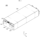
- FIG. 1 is a perspective view illustrating a battery module 100 according to an embodiment of the present disclosure.
- FIG. 2 is a partially exploded view of the battery module 100 shown in FIG. 1 .
- the battery module 100 includes a module frame 120, an insulating cover 130, an end plate 140, and a blocking structure 150.
- the module frame 120 is configured to accommodate a plurality of battery cells.
- the module frame 120 may have an inner space in which a plurality of battery cells is accommodated, and an opening 122 leading to the inner space.
- the module frame 120 may accommodate a battery cell assembly 110 including a plurality of battery cells in the inner space.
- the insulating cover 130 is configured to primarily cover the opening 122 of the module frame 120.
- the insulating cover 130 may be provided with a support 132 on which a terminal electrically connected to the plurality of battery cells accommodated in the module frame 120 is disposed and supported.
- the end plate 140 is configured to secondarily cover the opening 122 covered by the insulating cover 130.
- the end plate 140 may have a window W1 through which the support 132 of the insulating cover 130 is exposed to the outside.
- the blocking structure 150 is configured to cover the support 132 of the insulating cover 130 exposed through the window W1 of the end plate 140 and block an electrical short circuit between a terminal 118 disposed on the support 132 and the end plate 140. To this end, at least a portion of the blocking structure 150 may be configured to be located between the edges of the window W1 and the terminal 118.
- the module frame 120 may have an opening 122 at at least one end of the battery module 100 in the longitudinal direction ( ⁇ Y-axis direction) and accommodate a battery cell assembly 110 including a plurality of battery cells in the inner space leading to the opening 122.
- the module frame 120 may be configured in the form of a tube having openings provided at both ends thereof in the longitudinal direction ( ⁇ Y-axis direction).
- the module frame 120 may be made of a metal material with a high rigidity and heat resistance.
- the module frame 120 may be manufactured integrally through a sheet metal and welding process or an injection process.
- the module frame 120 may be made of clad metal obtained by bonding different types of metals. That is, the module frame 120 may be configured as a multi-layered metal plate in which a first metal plate and a second metal plate are bonded to each other.
- the first metal plate constituting the outer surface of the module frame 120 may be made of a material with higher thermal conductivity than the second metal plate constituting the inner surface of the module frame 120, and the second metal plate may be made of a material that has higher heat resistance and fire resistance than the first metal plate.
- the first metal plate may be made of a material including aluminum Al
- the second metal plate may be made of a material including stainless steel.
- the melting point of aluminum is approximately 660 degrees C
- the melting point of stainless steel is approximately 2750 degrees C.
- the insulating cover 130 may be configured to have a support 132 on which the terminal 118 is disposed and supported, and to primarily cover the opening 122 of the module frame 120.
- the insulating cover 130 may include a guide hole H1 that guides the terminal 118 to the support 132.
- the insulating cover 130 may include a first connector hole H2 through which a connector for transmitting electrical signals of battery cells included in the battery cell assembly 110 is exposed to the outside.
- the support 132 may include a seating portion having a seating surface on which the terminal 118 is seated and partitions that extend from the seating portion to edges of the window W1 provided on the end plate 140 and isolate the terminal 118 from the edges of the window W1.
- This insulating cover 130 may be made of polymer synthetic resin with electric insulation.
- the insulating cover 130 may be made of a material with high fire resistance as well as electric insulation.
- the end plate 140 may be configured to have the window W1 through which the support 132 of the insulating cover 130 is exposed to the outside and secondarily cover the opening 122 of the module frame 120 covered by the insulating cover 130.
- the end plate 140 may have a second connector hole H3, which is provided at a position corresponding to the first connector hole H2 of the insulating cover 130, through which the corresponding connector is exposed to the outside.
- the end plate 140 may be made of a metal material with a high rigidity and heat resistance.
- FIG. 3 is a diagram illustrating a battery cell assembly 110 of a battery module according to an embodiment of the present disclosure.
- the battery cell assembly 110 may include a plurality of battery cells 112, a bus-bar 114, and a bus-bar frame 116.
- the plurality of battery cells 112 may be densely arranged in the width direction ( ⁇ X-axis direction) of the battery module.
- Each battery cell 112 is the most fundamental secondary battery capable of being charged and discharged and may be implemented in various forms.
- the battery cell 112 may be implemented as a pouch-type secondary battery.
- the battery cell 112 may be manufactured by storing an electrode assembly and an electrolyte inside a pouch-shaped case and sealing the case.
- the pouch-shaped case may be comprised of one or two pouch sheets.
- the battery cell 112 may have a pair of electrode leads.
- Each electrode lead may be configured such that one end thereof is electrically connected to the electrode assembly accommodated inside the case and such that the other end extends and is exposed to the outside of the case.
- the plurality of battery cells 112 may be implemented as cylindrical secondary batteries or prismatic secondary batteries, respectively.
- the plurality of battery cells 112 may be stacked on each other in the horizontal direction ( ⁇ X-axis direction) while standing upright in the vertical direction ( ⁇ Z-axis direction).
- the bus-bar 114 may be configured to be electrically connected to the electrode lead of the battery cell 112 or the terminal 118. To this end, the bus-bar 114 may be made of a conductive material such as metal.
- the bus-bar frame 116 may be configured to support one or more bus-bars 114.
- the bus-bar frame 116 may be made of electrically insulating material. As will be explained below, the bus-bar frame 116 may be made of a material having high fire resistance as well as electric insulation.
- the battery cell assembly 110 may further include a terminal 118 that is electrically connected to the battery cells through the bus-bar 114 and provides the output voltage of the battery module 100, and a connector 119 that transmits electrical signals related to the battery cells.
- the terminal 118 and the connector 119 may be supported by the bus-bar frame 116.
- FIG. 4 illustrates a bus-bar frame 116 of the battery cell assembly 110 shown in FIG. 3 .
- the bus-bar frame 116 may be configured to be disposed in the inner space of the module frame 120, for example, between the plurality of battery cells accommodated in the module frame 120 and the insulating cover 130 covering the opening of the module frame 120, thereby supporting at least one bus-bar 114.
- each bus-bar 114 may be electrically connected to the electrode lead 112a of the battery cell 112 or the terminal 118 of the battery module 100.
- the terminal 118 which is electrically connected to the battery cells through the bus-bar 114, and the connector 119, which transmits electrical signals of the battery cells, may be supported by the bus-bar frame 116.
- This bus-bar frame 116 may be made of a material having high fire resistance as well as electric insulation.
- the bus-bar frame 116 may be made of a material including one or more of polyimide, aromatic polyamide, polyphenylene sulfide, polyether ether ketone, fluoropolymer, and ceramic.
- the bus-bar frame 116 which is disposed between the plurality of battery cells 112 included in the battery module and the insulating cover 130 to support the bus-bars, is made of a material with electric insulation and high fire resistance, it is possible to suppress structural deformation of the bus-bar frame even if high-temperature gas or flame is generated inside the battery module, thereby preventing an electrical short circuit resulting from contact between the bus-bars.
- FIG. 5 is a perspective view illustrating an insulating cover 130 of a battery module according to an embodiment of the present disclosure.
- the insulating cover 130 may be configured to have a support 132 and primarily cover the opening 122 of the module frame 120.
- the terminal 118 which is electrically connected to the battery cells of the battery cell assembly 110, is disposed and supported on the support 132.
- the insulating cover 130 may include a guide hole H1 that guides the terminal 118 to the support 132.
- the insulating cover 130 may include a first connector hole H2 through which a connector for transmitting electrical signals of battery cells included in the battery cell assembly 110 is exposed to the outside.
- the support 132 may include a seating portion 134 having a seating surface on which the terminal 118 is seated and partitions 136a and 136b that extend from the seating portion 134 to edges of the window W1 provided on the above-described end plate 140 and isolate the terminal 118 from the edges of the window W1.
- the partitions 136a and 136b may include a first partition 136a and a second partition 136b.
- the first partition 136a may be configured to extend downward from the bottom of the seating portion 134 so as to isolate the terminal 118 from an edge of the window W1 located below the seating portion 134.
- the second partition 136b may be configured to extend upward from the edge of the seating portion 134 so as to isolate the terminal 118 from another edge of the window W1 located on the side of the seating portion 134 or above the same.
- the terminal 118 of the battery module 100 is located inside the window W1 of the end plate 140, since the support 132 of the insulating cover 130 is configured to isolate the terminal 118 from the edges of the window W1 and block contact between the terminal 118 and the end plate 140, it is possible to prevent an electrical short circuit between the terminal 118 and the end plate 140 due to damage or collapse of the insulation structure even if high-temperature gas or flame is generated from the relevant battery module or from other battery modules adjacent to the relevant battery module, thereby suppressing thermal runaway of the battery module or the chain of thermal runaway between the battery modules.
- the support 132 of the insulating cover 130 may further include at least one coupling groove 138 into which at least a portion of a blocking structure configured to support the terminal 118 is inserted and coupled.
- the insulating cover 130 may be made of polymer synthetic resin with electric insulation.
- the insulating cover 130 may be made of a material with high fire resistance as well as electric insulation.
- the insulating cover 130 may be made of a material including one or more of polyimide, aromatic polyamide, polyphenylene sulfide, polyether ether ketone, fluoropolymer, and ceramic.
- the insulating cover 130 is made of a material with high fire resistance, it is possible to prevent or delay damage or collapse of the insulating cover due to high-temperature gas or flame, thereby further improving the electrical safety of the battery module.
- FIG. 6 is a perspective view illustrating an end plate 140 of a battery module according to an embodiment of the present disclosure.
- the end plate 140 may be configured to have a window W1 through which the support 132 of the insulating cover 130 is exposed to the outside and secondarily cover the opening 122 of the module frame 120 covered by the insulating cover 130.
- the end plate 140 may have a second connector hole H3, which is provided at a position corresponding to the first connector hole H2 of the insulating cover 130, through which the connector 119 inserted into the first connector hole H2 is exposed to the outside.
- the end plate 140 may include coupling portions 142 and 144 to which a blocking structure 150 configured to support the terminal 118 is coupled.
- the end plate 140 may further include a support portion 146 that comes into contact with a portion of the blocking structure 150 and supports the blocking structure 150 .
- the end plate 140 may be made of a metal material with high rigidity and heat resistance.
- the end plate 140 may be coupled to the module frame 120 by laser welding so as to cover the opening 122 of the module frame 120 described above.
- the battery module 100 may further include, in addition to the end plate 140 that covers the opening at one end of the module frame 120, the other end plate that covers the opening at the other end of the module frame 120.
- the other end plate may exclude the configurations corresponding to the window W1, the second connector hole H3, the coupling portions 142 and 144, and the support portion 146 of the end plate 140.
- FIG. 7 is a front perspective view illustrating a blocking structure 150 of a battery module according to an embodiment of the present disclosure.
- FIG. 8 is a rear perspective view illustrating the blocking structure 150 shown in FIG. 7 .
- the blocking structure 150 may be configured to cover the support 132 of the insulating cover 130 exposed through the window W1 of the end plate 140 and block an electrical short circuit between the terminal 118 disposed on the support 132 and the end plate 140.
- the blocking structure 150 may be configured to be coupled and fixed to the end plate 140, which is generally made of a metal material.
- the blocking structure 150 may include coupling portions 152 and 154 coupled to the end plate 140, and a cover portion 156 that is supported by the coupling portions 152 and 154 and covers the support 132 of the insulating cover 130.
- the coupling portions 152 and 154 may be coupled to the end plate 140 in various ways.
- the coupling portions 152 and 154 may be coupled to the end plate 140 by screws, fitting, adhesives, or a combination of two or more thereof.
- the coupling portions 152 and 154 may include a first coupling portion 152 coupled to one portion (142 in FIG. 6 ) of the end plate 140 and a second coupling portion 154 coupled to another portion (144 in FIG. 6 ) of the end plate 140.
- the blocking structure 150 may have an alignment groove 152a into which the second partition 136b of the support 132 described above is inserted. If the second partition 136b of the support 132 is accurately inserted into the alignment groove 152a of the blocking structure 150, other portions of the blocking structure 150 may be disposed at correct positions.
- the cover portion 156 may be configured to cover the support 132 exposed through the window W1 of the end plate 140. Depending on the embodiment, the cover portion 156 may be configured to cover at least a portion of the terminal 118 disposed on the support 132.
- the cover portion 156 may be formed integrally with the coupling portions 152 and 154.
- the blocking structure 150 may include at least one blocking fin 158.
- the at least one blocking fin 158 may be configured to be located between the edge of the window W1 and the terminal 118 and come into contact with the terminal 118 disposed on the support 132 of the insulating cover 130 to support the terminal 118, thereby blocking contact between the terminal 118 and the end plate even when the insulating cover 130 melts.
- each blocking fin 158 may be configured to protrude from the cover portion 156 toward the support 132 of the insulating cover 130 to come into contact with the terminal 118 disposed on the support 132.
- the support 132 of the insulating cover 130 may have at least one coupling groove (158 in FIG. 5 ) into which the at least one blocking fin 158 is inserted and coupled.
- the at least one blocking fin 158 may be formed integrally with the cover portion 156.
- the blocking structure 150 may be made of a material that has electric insulation and fire resistance.
- the blocking structure 150 may be made of a refractory material with a higher melting point than the insulating cover 130.
- the blocking structure 150 may be made of a material including silicon or ceramic.
- the blocking structure 150 made of a refractory material with a higher melting point than the insulating cover 130 is coupled to the support 132 of the insulating cover 130 and supports the terminal 118 seated on the support 132, thereby preventing an electrical short circuit between the terminal 118 and the end plate 140 even if the insulating cover 130 melts or collapses due to high-temperature gas or flame.
- the blocking structure 150 is coupled and fixed to the end plate 140 made of metal, the terminal 118 may be safely supported even when the insulating cover 130 melts or collapses.
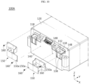
- FIG. 9 illustrates a battery module 100A according to a modified embodiment of the present disclosure.
- FIG. 10 is a partially exploded view illustrating the battery module 100A shown in FIG. 9 .
- the battery module 100A may further include a fixing screw 160.
- the fixing screw 160 may be configured to fix the coupling portions 152 and 154 of the blocking structure 150 to the end plate 140.
- the blocking structure 150 may have a through-hole 150a through which the body of the fixing screw 160 passes.
- the end plate 140 may have a screw hole 148 with which the fixing screw 160 is fastened.
- the blocking structure 150 is fixed to the end plate 140 by the fixing screw 160, thereby preventing the blocking structure from being separated from the battery module by high-pressure gas discharged from the inside of the battery module.
- FIG. 11 is a diagram illustrating a battery pack 10 according to an embodiment of the present disclosure.
- the battery pack 10 may include the battery module 100 or 100A according to the various embodiments described above.
- the battery pack 10 may further include a pack case 12 and 14 accommodating one or more battery modules 100 or 100A.
- the pack case 12 and 14 may include a pack tray 12 having an accommodation space for accommodating a plurality of battery modules, and a pack lid 14 that covers the top opening of the pack tray 12.
- the battery pack 10 may further include various electrical components (not shown) that control the charging and discharging operation of the battery module 100 or 100A accommodated in the pack case 12 and 14 or the battery cell included in the battery module 100 or 100A, or monitor SOC (State of Charge), SOH (State of Health), or the like. These electronic components may be accommodated in the pack case 12 and 14 along with the battery module 100.
- FIG. 12 is a diagram illustrating a vehicle 2 according to an embodiment of the present disclosure.
- the vehicle 2 may include the battery module 100 or 100A according to the various embodiments described above.
- the vehicle 2 may include a battery pack 10 including one or more battery modules 100 or 100A.
- the battery module 100 or 100A or the battery pack 10 including the same may supply the electric energy required for various operations of the vehicle 2.
- the vehicle 2 may further include an electric motor that drives the vehicle 2 using the electric energy supplied from the battery module 100 or 100A or the battery pack 10 including the same.
- the battery module 100 or 100A according to the present disclosure may be applied to various electric devices or electric systems that use electric energy, in addition to vehicles, as well as to ESSs (Energy Storage Systems).
- ESSs Electronic Switches
- the support of the insulating cover on which the terminal of the battery module is disposed is exposed through the window of the end plate, and the blocking structure covers the support exposed through the window and blocks an electrical short circuit between the terminal disposed on the support and the end plate, thereby preventing an electrical short circuit between the terminal and the end plate even if high-temperature gases, flames, foreign substances, or the like are emitted from the relevant battery module or from other battery modules adjacent to the relevant battery module and, as a result, suppressing thermal runaway of the battery module or the chain of thermal runaway between the battery modules.
- the support of the insulating cover is configured to isolate the terminal from the end plate and block contact between the terminal and the end plate, thereby securing electrical safety of the battery module.
- the insulating cover is made of a fire-resistant material, it is possible to prevent or at least delay damage or collapse of the insulating cover due to high-temperature gas or flame, thereby further improving the electrical safety of the battery module.
- the blocking structure is configured to come into direct contact with the terminal disposed on the support and support the terminal, thereby preventing an electrical short circuit between the terminal and the end plate even if the insulating cover melts or collapses due to high-temperature gas or flame.
- the blocking structure is configured to be coupled and fixed to the end plate, which is generally made of a metal material, thereby preventing the blocking structure from being separated from the battery module by high-pressure gas discharged from the inside of the battery module.
Landscapes
- Chemical & Material Sciences (AREA)
- Chemical Kinetics & Catalysis (AREA)
- Electrochemistry (AREA)
- General Chemical & Material Sciences (AREA)
- Engineering & Computer Science (AREA)
- Aviation & Aerospace Engineering (AREA)
- Manufacturing & Machinery (AREA)
- Battery Mounting, Suspending (AREA)
- Connection Of Batteries Or Terminals (AREA)
Abstract
Description
- The present application claims priority to
Korean Patent Application No. 10-2023-0017551 filed on February 09, 2023 Korean Patent Application No. 10-2023-0097768 filed on July 26, 2023 - The present disclosure relates to a battery module, and a battery pack and a vehicle including the same, and more specifically, it relates to a battery module having a plurality of battery cells capable of being charged and discharged, and a battery pack and a vehicle including the battery module.
- In general, secondary batteries refer to batteries capable of being repeatedly charged and discharged, such as lithium-ion batteries, lithium-polymer batteries, nickel-cadmium batteries, nickel-hydrogen batteries, nickel-zinc batteries, and the like. A battery cell, which is the most fundamental secondary battery, may provide an output voltage of approximately 2.5V to 4.2V.
- Recently, the secondary batteries have been applied to devices that require high output voltage and a large amount of charging capacity, such as electric vehicles or ESSs (Energy Storage Systems), and accordingly, a battery pack, which is manufactured in a manner of configuring a battery module by connecting a plurality of battery cells in series, parallel, or a combination thereof and reconnecting these battery modules in series, parallel, or a combination thereof, has been widely used.
- In order to increase the energy density of the battery module or battery pack, multiple battery cells are densely disposed in a limited space inside the battery module or battery pack. Therefore, the battery module or battery pack must be designed to have high durability and electrical safety in consideration of the risk of thermal runaway of the battery cells or thermal propagation therebetween.
- However, as disclosed in
Korean Unexamined Patent Publication No. 10-2021-0104429 - This problem, in a battery pack with a layout where the terminal of a battery module faces the terminal of another battery module, may accelerate the chain of thermal runaway or ignition of battery modules and incur a high risk such as explosion of the battery pack.
- The present disclosure has been designed to solve the problems of the related art, and therefore the present disclosure is directed to providing a battery module that prevents an electrical short circuit between the terminal of the battery module and the end plate even when high-temperature gases, flames, foreign substances, or the like are emitted from the inside of the battery module or from other battery modules adjacent to the battery module, and a battery pack and a vehicle including the same.
- A battery module according to one aspect of the present disclosure includes: a module frame having an inner space in which a plurality of battery cells is accommodated and an opening leading to the inner space; an insulating cover including a support on which a terminal electrically connected to the plurality of battery cells is disposed and supported, and configured to primarily cover the opening; an end plate having a window through which the support is exposed to the outside and configured to secondarily cover the opening covered by the insulating cover; and a blocking structure configured to cover the support exposed through the window and block an electrical short circuit between the terminal disposed on the support and the end plate.
- In an embodiment, the support of the insulating cover may include: a seating portion having a seating surface on which the terminal is seated; and partitions extending from the seating portion toward edges of the window so as to isolate the terminal from the edges of the window.
- In an embodiment, the partitions may include: a first partition extending downward from a bottom of the seating portion so as to isolate the terminal from a first edge of the window located below the seating portion; and a second partition extending upward from an edge of the seating portion so as to isolate the terminal from a second edge of the window located on a side of the seating portion or above the same.
- In an embodiment, the insulating cover may be made of a material having electric insulation and fire resistance.
- In an embodiment, the insulating cover may be made of a material including one or more of polyimide, aromatic polyamide, polyphenylene sulfide, polyether ether ketone, and fluoropolymer.
- In an embodiment, the blocking structure may include: a coupling portion coupled to the end plate; and a cover portion supported by the coupling portion and configured to cover the support.
- In an embodiment, the blocking structure may further include at least one blocking fin configured to contact and support the terminal, thereby blocking contact between the terminal and the end plate when the insulating cover melts.
- In an embodiment, the at least one blocking fin may be configured to protrude from the cover portion toward the support and contact the terminal disposed on the support.
- In an embodiment, the support may have at least one coupling groove into which the at least one blocking fin is inserted and coupled.
- In an embodiment, the battery module may further include at least one fixing screw configured to fix the coupling portion to the end plate.
- In an embodiment, the blocking structure may be made of a material having electric insulation and fire resistance.
- In an embodiment, the blocking structure may be made of a material including silicon or ceramic.
- In an embodiment, the blocking structure may be made of a material having a higher melting point than a melting point of the insulating cover.
- A battery pack according to another aspect of the present disclosure may include the battery module according to any one of the embodiments described above.
- A vehicle according to another aspect of the present disclosure may include the battery module according to any one of the embodiments described above.
- According to the present disclosure, the support of the insulating cover, on which the terminal of the battery module is disposed, is exposed through the window of the end plate, and the blocking structure covers the support exposed through the window and blocks an electrical short circuit between the terminal disposed on the support and the end plate, thereby preventing an electrical short circuit between the terminal and the end plate even if high-temperature gases, flames, foreign substances, or the like are emitted from the relevant battery module or from other battery modules adjacent to the relevant battery module and, as a result, suppressing thermal runaway of the battery module or the chain of thermal runaway between the battery modules.
- In addition, the support of the insulating cover is configured to isolate the terminal from the end plate and block contact between the terminal and the end plate, thereby securing electrical safety of the battery module.
- In addition, since the insulating cover is made of a fire-resistant material, it is possible to prevent or at least delay damage or collapse of the insulating cover due to high-temperature gas or flame, thereby further improving the electrical safety of the battery module.
- In addition, the blocking structure is configured to come into direct contact with the terminal disposed on the support and support the terminal, thereby preventing an electrical short circuit between the terminal and the end plate even if the insulating cover melts or collapses due to high-temperature gas or flame.
- In addition, the blocking structure is configured to be coupled and fixed to the end plate, which is generally made of a metal material, thereby preventing the blocking structure from being separated from the battery module by high-pressure gas discharged from the inside of the battery module.
- Furthermore, those skilled in the art to which the present disclosure pertains will be able to clearly understand from the following description that various embodiments according to the present disclosure are able to solve various technical problems not mentioned above.
-
-
FIG. 1 is a perspective view illustrating a battery module according to an embodiment of the present disclosure. -
FIG. 2 is a partially exploded view of the battery module shown inFIG. 1 . -
FIG. 3 is a diagram illustrating a battery cell assembly of a battery module according to an embodiment of the present disclosure. -
FIG. 4 is a diagram illustrating a bus-bar frame of the battery cell assembly shown inFIG. 3 . -
FIG. 5 is a diagram illustrating an insulating cover of a battery module according to an embodiment of the present disclosure. -
FIG. 6 is a diagram illustrating an end plate of a battery module according to an embodiment of the present disclosure. -
FIG. 7 is a front perspective view illustrating a blocking structure of a battery module according to an embodiment of the present disclosure. -
FIG. 8 is a rear perspective view illustrating the blocking structure shown inFIG. 7 . -
FIG. 9 is a diagram illustrating a battery module according to a modified embodiment of the present disclosure. -
FIG. 10 is a partially exploded view illustrating the battery module shown inFIG. 9 . -
FIG. 11 is a diagram illustrating a battery pack according to an embodiment of the present disclosure. -
FIG. 12 is a diagram illustrating a vehicle according to an embodiment of the present disclosure. - Hereinafter, embodiments according to the present disclosure will be described in detail with reference to the accompanying drawings to clarify solutions corresponding to the technical problems of the present disclosure. However, in describing the present disclosure, a description of related known technology, which may obscure the subject matter of the present disclosure, may be omitted. In addition, the terms used in this specification are defined in consideration of the functions in the present disclosure and may vary depending on the intention of the designer, manufacturer, etc. or custom thereof. Therefore, definitions of the terms described below should be made based on the description throughout this specification.
-
FIG. 1 is a perspective view illustrating abattery module 100 according to an embodiment of the present disclosure. -
FIG. 2 is a partially exploded view of thebattery module 100 shown inFIG. 1 . - As shown in
FIGS. 1 and2 , thebattery module 100 according to an embodiment of the present disclosure includes amodule frame 120, aninsulating cover 130, anend plate 140, and ablocking structure 150. - The
module frame 120 is configured to accommodate a plurality of battery cells. To this end, themodule frame 120 may have an inner space in which a plurality of battery cells is accommodated, and anopening 122 leading to the inner space. For example, themodule frame 120 may accommodate abattery cell assembly 110 including a plurality of battery cells in the inner space. - The
insulating cover 130 is configured to primarily cover the opening 122 of themodule frame 120. Theinsulating cover 130 may be provided with asupport 132 on which a terminal electrically connected to the plurality of battery cells accommodated in themodule frame 120 is disposed and supported. - The
end plate 140 is configured to secondarily cover the opening 122 covered by theinsulating cover 130. Theend plate 140 may have a window W1 through which thesupport 132 of theinsulating cover 130 is exposed to the outside. - The
blocking structure 150 is configured to cover thesupport 132 of theinsulating cover 130 exposed through the window W1 of theend plate 140 and block an electrical short circuit between aterminal 118 disposed on thesupport 132 and theend plate 140. To this end, at least a portion of the blockingstructure 150 may be configured to be located between the edges of the window W1 and the terminal 118. - For example, the
module frame 120 may have anopening 122 at at least one end of thebattery module 100 in the longitudinal direction (±Y-axis direction) and accommodate abattery cell assembly 110 including a plurality of battery cells in the inner space leading to theopening 122. - In this case, the
module frame 120 may be configured in the form of a tube having openings provided at both ends thereof in the longitudinal direction (±Y-axis direction). In addition, themodule frame 120 may be made of a metal material with a high rigidity and heat resistance. Themodule frame 120 may be manufactured integrally through a sheet metal and welding process or an injection process. - In an embodiment, the
module frame 120 may be made of clad metal obtained by bonding different types of metals. That is, themodule frame 120 may be configured as a multi-layered metal plate in which a first metal plate and a second metal plate are bonded to each other. - In this case, the first metal plate constituting the outer surface of the
module frame 120 may be made of a material with higher thermal conductivity than the second metal plate constituting the inner surface of themodule frame 120, and the second metal plate may be made of a material that has higher heat resistance and fire resistance than the first metal plate. For example, the first metal plate may be made of a material including aluminum Al, and the second metal plate may be made of a material including stainless steel. For reference, the melting point of aluminum is approximately 660 degrees C, and the melting point of stainless steel is approximately 2750 degrees C. - As described above, the insulating
cover 130 may be configured to have asupport 132 on which the terminal 118 is disposed and supported, and to primarily cover theopening 122 of themodule frame 120. - In this case, the insulating
cover 130 may include a guide hole H1 that guides the terminal 118 to thesupport 132. In addition, the insulatingcover 130 may include a first connector hole H2 through which a connector for transmitting electrical signals of battery cells included in thebattery cell assembly 110 is exposed to the outside. - As will be explained below, the
support 132 may include a seating portion having a seating surface on which the terminal 118 is seated and partitions that extend from the seating portion to edges of the window W1 provided on theend plate 140 and isolate the terminal 118 from the edges of the window W1. - This insulating
cover 130 may be made of polymer synthetic resin with electric insulation. In particular, the insulatingcover 130 may be made of a material with high fire resistance as well as electric insulation. - The
end plate 140 may be configured to have the window W1 through which thesupport 132 of the insulatingcover 130 is exposed to the outside and secondarily cover theopening 122 of themodule frame 120 covered by the insulatingcover 130. In addition, theend plate 140 may have a second connector hole H3, which is provided at a position corresponding to the first connector hole H2 of the insulatingcover 130, through which the corresponding connector is exposed to the outside. - The
end plate 140 may be made of a metal material with a high rigidity and heat resistance. -
FIG. 3 is a diagram illustrating abattery cell assembly 110 of a battery module according to an embodiment of the present disclosure. - As shown in
FIG. 3 , thebattery cell assembly 110 may include a plurality ofbattery cells 112, a bus-bar 114, and a bus-bar frame 116. - The plurality of
battery cells 112 may be densely arranged in the width direction (±X-axis direction) of the battery module. Eachbattery cell 112 is the most fundamental secondary battery capable of being charged and discharged and may be implemented in various forms. - For example, the
battery cell 112 may be implemented as a pouch-type secondary battery. In this case, thebattery cell 112 may be manufactured by storing an electrode assembly and an electrolyte inside a pouch-shaped case and sealing the case. In this case, the pouch-shaped case may be comprised of one or two pouch sheets. - The
battery cell 112 may have a pair of electrode leads. Each electrode lead may be configured such that one end thereof is electrically connected to the electrode assembly accommodated inside the case and such that the other end extends and is exposed to the outside of the case. - In another embodiment, the plurality of
battery cells 112 may be implemented as cylindrical secondary batteries or prismatic secondary batteries, respectively. - As shown in
FIG. 3 , the plurality ofbattery cells 112 may be stacked on each other in the horizontal direction (±X-axis direction) while standing upright in the vertical direction (±Z-axis direction). - The bus-
bar 114 may be configured to be electrically connected to the electrode lead of thebattery cell 112 or the terminal 118. To this end, the bus-bar 114 may be made of a conductive material such as metal. - The bus-
bar frame 116 may be configured to support one or more bus-bars 114. The bus-bar frame 116 may be made of electrically insulating material. As will be explained below, the bus-bar frame 116 may be made of a material having high fire resistance as well as electric insulation. - In addition, the
battery cell assembly 110 may further include a terminal 118 that is electrically connected to the battery cells through the bus-bar 114 and provides the output voltage of thebattery module 100, and aconnector 119 that transmits electrical signals related to the battery cells. In this case, the terminal 118 and theconnector 119 may be supported by the bus-bar frame 116. -
FIG. 4 illustrates a bus-bar frame 116 of thebattery cell assembly 110 shown inFIG. 3 . - As shown in
FIG. 4 , the bus-bar frame 116 may be configured to be disposed in the inner space of themodule frame 120, for example, between the plurality of battery cells accommodated in themodule frame 120 and the insulatingcover 130 covering the opening of themodule frame 120, thereby supporting at least one bus-bar 114. In this case, each bus-bar 114 may be electrically connected to theelectrode lead 112a of thebattery cell 112 or theterminal 118 of thebattery module 100. - The terminal 118, which is electrically connected to the battery cells through the bus-
bar 114, and theconnector 119, which transmits electrical signals of the battery cells, may be supported by the bus-bar frame 116. - This bus-
bar frame 116 may be made of a material having high fire resistance as well as electric insulation. For example, the bus-bar frame 116 may be made of a material including one or more of polyimide, aromatic polyamide, polyphenylene sulfide, polyether ether ketone, fluoropolymer, and ceramic. - As described above, since the bus-
bar frame 116, which is disposed between the plurality ofbattery cells 112 included in the battery module and the insulatingcover 130 to support the bus-bars, is made of a material with electric insulation and high fire resistance, it is possible to suppress structural deformation of the bus-bar frame even if high-temperature gas or flame is generated inside the battery module, thereby preventing an electrical short circuit resulting from contact between the bus-bars. -
FIG. 5 is a perspective view illustrating an insulatingcover 130 of a battery module according to an embodiment of the present disclosure. - As shown in
FIG. 5 , the insulatingcover 130 may be configured to have asupport 132 and primarily cover theopening 122 of themodule frame 120. The terminal 118, which is electrically connected to the battery cells of thebattery cell assembly 110, is disposed and supported on thesupport 132. To this end, the insulatingcover 130 may include a guide hole H1 that guides the terminal 118 to thesupport 132. - Depending on the embodiment, the insulating
cover 130 may include a first connector hole H2 through which a connector for transmitting electrical signals of battery cells included in thebattery cell assembly 110 is exposed to the outside. - In addition, the
support 132 may include aseating portion 134 having a seating surface on which the terminal 118 is seated andpartitions seating portion 134 to edges of the window W1 provided on the above-describedend plate 140 and isolate the terminal 118 from the edges of the window W1. - In this case, the
partitions first partition 136a and asecond partition 136b. - The
first partition 136a may be configured to extend downward from the bottom of theseating portion 134 so as to isolate the terminal 118 from an edge of the window W1 located below theseating portion 134. - The
second partition 136b may be configured to extend upward from the edge of theseating portion 134 so as to isolate the terminal 118 from another edge of the window W1 located on the side of theseating portion 134 or above the same. - As described above, although the
terminal 118 of thebattery module 100 is located inside the window W1 of theend plate 140, since thesupport 132 of the insulatingcover 130 is configured to isolate the terminal 118 from the edges of the window W1 and block contact between the terminal 118 and theend plate 140, it is possible to prevent an electrical short circuit between the terminal 118 and theend plate 140 due to damage or collapse of the insulation structure even if high-temperature gas or flame is generated from the relevant battery module or from other battery modules adjacent to the relevant battery module, thereby suppressing thermal runaway of the battery module or the chain of thermal runaway between the battery modules. - As will be described below, the
support 132 of the insulatingcover 130 may further include at least onecoupling groove 138 into which at least a portion of a blocking structure configured to support the terminal 118 is inserted and coupled. - The insulating
cover 130 may be made of polymer synthetic resin with electric insulation. In particular, the insulatingcover 130 may be made of a material with high fire resistance as well as electric insulation. - For example, the insulating
cover 130 may be made of a material including one or more of polyimide, aromatic polyamide, polyphenylene sulfide, polyether ether ketone, fluoropolymer, and ceramic. - As described above, since the insulating
cover 130 is made of a material with high fire resistance, it is possible to prevent or delay damage or collapse of the insulating cover due to high-temperature gas or flame, thereby further improving the electrical safety of the battery module. -
FIG. 6 is a perspective view illustrating anend plate 140 of a battery module according to an embodiment of the present disclosure. - As shown in
FIG. 6 , theend plate 140 may be configured to have a window W1 through which thesupport 132 of the insulatingcover 130 is exposed to the outside and secondarily cover theopening 122 of themodule frame 120 covered by the insulatingcover 130. - In addition, the
end plate 140 may have a second connector hole H3, which is provided at a position corresponding to the first connector hole H2 of the insulatingcover 130, through which theconnector 119 inserted into the first connector hole H2 is exposed to the outside. - As will be described below, the
end plate 140 may includecoupling portions structure 150 configured to support the terminal 118 is coupled. In addition, theend plate 140 may further include asupport portion 146 that comes into contact with a portion of the blockingstructure 150 and supports the blockingstructure 150 . - The
end plate 140 may be made of a metal material with high rigidity and heat resistance. In addition, theend plate 140 may be coupled to themodule frame 120 by laser welding so as to cover theopening 122 of themodule frame 120 described above. Meanwhile, in the case where openings are provided at both ends of themodule frame 120, thebattery module 100 may further include, in addition to theend plate 140 that covers the opening at one end of themodule frame 120, the other end plate that covers the opening at the other end of themodule frame 120. In this case, the other end plate may exclude the configurations corresponding to the window W1, the second connector hole H3, thecoupling portions support portion 146 of theend plate 140. -
FIG. 7 is a front perspective view illustrating a blockingstructure 150 of a battery module according to an embodiment of the present disclosure. -
FIG. 8 is a rear perspective view illustrating the blockingstructure 150 shown inFIG. 7 . - As shown in
FIGS. 7 and8 , the blockingstructure 150 may be configured to cover thesupport 132 of the insulatingcover 130 exposed through the window W1 of theend plate 140 and block an electrical short circuit between the terminal 118 disposed on thesupport 132 and theend plate 140. The blockingstructure 150 may be configured to be coupled and fixed to theend plate 140, which is generally made of a metal material. - To this end, the blocking
structure 150 may includecoupling portions end plate 140, and acover portion 156 that is supported by thecoupling portions support 132 of the insulatingcover 130. - In this case, the
coupling portions end plate 140 in various ways. For example, thecoupling portions end plate 140 by screws, fitting, adhesives, or a combination of two or more thereof. - In an embodiment, the
coupling portions first coupling portion 152 coupled to one portion (142 inFIG. 6 ) of theend plate 140 and asecond coupling portion 154 coupled to another portion (144 inFIG. 6 ) of theend plate 140. - In an embodiment, the blocking
structure 150 may have analignment groove 152a into which thesecond partition 136b of thesupport 132 described above is inserted. If thesecond partition 136b of thesupport 132 is accurately inserted into thealignment groove 152a of the blockingstructure 150, other portions of the blockingstructure 150 may be disposed at correct positions. - The
cover portion 156 may be configured to cover thesupport 132 exposed through the window W1 of theend plate 140. Depending on the embodiment, thecover portion 156 may be configured to cover at least a portion of the terminal 118 disposed on thesupport 132. - The
cover portion 156 may be formed integrally with thecoupling portions - In addition, in an embodiment, the blocking
structure 150 may include at least one blockingfin 158. In this case, the at least one blockingfin 158 may be configured to be located between the edge of the window W1 and the terminal 118 and come into contact with the terminal 118 disposed on thesupport 132 of the insulatingcover 130 to support the terminal 118, thereby blocking contact between the terminal 118 and the end plate even when the insulatingcover 130 melts. - In this case, each blocking
fin 158 may be configured to protrude from thecover portion 156 toward thesupport 132 of the insulatingcover 130 to come into contact with the terminal 118 disposed on thesupport 132. To this end, thesupport 132 of the insulatingcover 130 may have at least one coupling groove (158 inFIG. 5 ) into which the at least one blockingfin 158 is inserted and coupled. - The at least one blocking
fin 158 may be formed integrally with thecover portion 156. - In addition, the blocking
structure 150 may be made of a material that has electric insulation and fire resistance. In this case, the blockingstructure 150 may be made of a refractory material with a higher melting point than the insulatingcover 130. For example, the blockingstructure 150 may be made of a material including silicon or ceramic. - As described above, the blocking
structure 150 made of a refractory material with a higher melting point than the insulatingcover 130 is coupled to thesupport 132 of the insulatingcover 130 and supports the terminal 118 seated on thesupport 132, thereby preventing an electrical short circuit between the terminal 118 and theend plate 140 even if the insulatingcover 130 melts or collapses due to high-temperature gas or flame. - In addition, since the blocking
structure 150 is coupled and fixed to theend plate 140 made of metal, the terminal 118 may be safely supported even when the insulatingcover 130 melts or collapses. -
FIG. 9 illustrates abattery module 100A according to a modified embodiment of the present disclosure. -
FIG. 10 is a partially exploded view illustrating thebattery module 100A shown inFIG. 9 . - As shown in
FIGS. 9 and10 , thebattery module 100A according to a modified embodiment may further include a fixingscrew 160. - The fixing
screw 160 may be configured to fix thecoupling portions structure 150 to theend plate 140. In this case, the blockingstructure 150 may have a through-hole 150a through which the body of the fixingscrew 160 passes. In addition, theend plate 140 may have ascrew hole 148 with which the fixingscrew 160 is fastened. - As described above, the blocking
structure 150 is fixed to theend plate 140 by the fixingscrew 160, thereby preventing the blocking structure from being separated from the battery module by high-pressure gas discharged from the inside of the battery module. -
FIG. 11 is a diagram illustrating abattery pack 10 according to an embodiment of the present disclosure. - As shown in
FIG. 11 , thebattery pack 10 according to an embodiment of the present disclosure may include thebattery module battery pack 10 may further include apack case more battery modules - The
pack case pack tray 12 having an accommodation space for accommodating a plurality of battery modules, and apack lid 14 that covers the top opening of thepack tray 12. - In addition, the
battery pack 10 may further include various electrical components (not shown) that control the charging and discharging operation of thebattery module pack case battery module pack case battery module 100. -
FIG. 12 is a diagram illustrating avehicle 2 according to an embodiment of the present disclosure. - As shown in
FIG. 12 , thevehicle 2 according to an embodiment of the present disclosure may include thebattery module vehicle 2 may include abattery pack 10 including one ormore battery modules battery module battery pack 10 including the same may supply the electric energy required for various operations of thevehicle 2. - In this case, the
vehicle 2 may further include an electric motor that drives thevehicle 2 using the electric energy supplied from thebattery module battery pack 10 including the same. - For reference, the
battery module - According to the present disclosure, the support of the insulating cover on which the terminal of the battery module is disposed is exposed through the window of the end plate, and the blocking structure covers the support exposed through the window and blocks an electrical short circuit between the terminal disposed on the support and the end plate, thereby preventing an electrical short circuit between the terminal and the end plate even if high-temperature gases, flames, foreign substances, or the like are emitted from the relevant battery module or from other battery modules adjacent to the relevant battery module and, as a result, suppressing thermal runaway of the battery module or the chain of thermal runaway between the battery modules.
- In addition, the support of the insulating cover is configured to isolate the terminal from the end plate and block contact between the terminal and the end plate, thereby securing electrical safety of the battery module.
- In addition, since the insulating cover is made of a fire-resistant material, it is possible to prevent or at least delay damage or collapse of the insulating cover due to high-temperature gas or flame, thereby further improving the electrical safety of the battery module.
- In addition, the blocking structure is configured to come into direct contact with the terminal disposed on the support and support the terminal, thereby preventing an electrical short circuit between the terminal and the end plate even if the insulating cover melts or collapses due to high-temperature gas or flame.
- In addition, the blocking structure is configured to be coupled and fixed to the end plate, which is generally made of a metal material, thereby preventing the blocking structure from being separated from the battery module by high-pressure gas discharged from the inside of the battery module.
- Furthermore, the embodiments according to the present disclosure are able to solve various technical problems other than those mentioned in this specification in the relevant technical field as well as related technical fields.
- So far, the present disclosure has been described with reference to specific embodiments. However, those skilled in the art will clearly understand that various modified embodiments may be implemented within the technical scope of the present disclosure. Therefore, the previously disclosed embodiments should be considered as those intended to describe the present disclosure, instead of those intended to limit the present disclosure. In other words, the true scope of the technical idea of the present disclosure is shown in the claims, and all differences within the scope equivalent thereto should be construed as being included in the present disclosure.
Claims (15)
- A battery module comprising:a module frame having an inner space in which a plurality of battery cells is accommodated and an opening leading to the inner space;an insulating cover comprising a support on which a terminal electrically connected to the plurality of battery cells is disposed and supported, and configured to primarily cover the opening;an end plate having a window through which the support is exposed to the outside and configured to secondarily cover the opening covered by the insulating cover; anda blocking structure configured to cover the support exposed through the window and block an electrical short circuit between the terminal disposed on the support and the end plate.
- The battery module according to claim 1, wherein the support of the insulating cover comprises:a seating portion having a seating surface on which the terminal is seated; andpartitions extending from the seating portion toward edges of the window so as to isolate the terminal from the edges of the window.
- The battery module according to claim 2, wherein the partitions comprise:a first partition extending downward from a bottom of the seating portion so as to isolate the terminal from a first edge of the window located below the seating portion; anda second partition extending upward from an edge of the seating portion so as to isolate the terminal from a second edge of the window located on a side of the seating portion or above the same.
- The battery module according to claim 1, wherein the insulating cover is made of a material having electric insulation and fire resistance.
- The battery module according to claim 4, wherein the insulating cover is made of a material comprising one or more of polyimide, aromatic polyamide, polyphenylene sulfide, polyether ether ketone, and fluoropolymer.
- The battery module according to claim 1, wherein the blocking structure comprises:a coupling portion coupled to the end plate; anda cover portion supported by the coupling portion and configured to cover the support.
- The battery module according to claim 6, wherein the blocking structure further comprises at least one blocking fin configured to contact and support the terminal, thereby blocking contact between the terminal and the end plate when the insulating cover melts.
- The battery module according to claim 7, wherein the at least one blocking fin is configured to protrude from the cover portion toward the support and contact the terminal disposed on the support.
- The battery module according to claim 7, wherein the support has at least one coupling groove into which the at least one blocking fin is inserted and coupled.
- The battery module according to claim 6, further comprising at least one fixing screw configured to fix the coupling portion to the end plate.
- The battery module according to claim 1, wherein the blocking structure is made of a material having electric insulation and fire resistance.
- The battery module according to claim 11, wherein the blocking structure is made of a material comprising silicon or ceramic.
- The battery module according to claim 1, wherein the blocking structure is made of a material having a higher melting point than a melting point of the insulating cover.
- A battery pack comprising the battery module according to any one of claims 1 to 13.
- A vehicle comprising the battery module according to any one of claims 1 to 13.
Applications Claiming Priority (3)
| Application Number | Priority Date | Filing Date | Title |
|---|---|---|---|
| KR20230017551 | 2023-02-09 | ||
| KR1020230097768A KR20240124792A (en) | 2023-02-09 | 2023-07-26 | Battery module, and battery pack and vehicle including same |
| PCT/KR2023/020572 WO2024167124A1 (en) | 2023-02-09 | 2023-12-13 | Battery module, and battery pack and vehicle including same |
Publications (2)
| Publication Number | Publication Date |
|---|---|
| EP4478526A1 true EP4478526A1 (en) | 2024-12-18 |
| EP4478526A4 EP4478526A4 (en) | 2025-06-11 |
Family
ID=92263161
Family Applications (1)
| Application Number | Title | Priority Date | Filing Date |
|---|---|---|---|
| EP23921496.8A Pending EP4478526A4 (en) | 2023-02-09 | 2023-12-13 | BATTERY MODULE AND BATTERY PACK AND VEHICLE THEREWITH |
Country Status (5)
| Country | Link |
|---|---|
| US (1) | US20250337139A1 (en) |
| EP (1) | EP4478526A4 (en) |
| JP (1) | JP2025518576A (en) |
| CN (1) | CN119054143A (en) |
| WO (1) | WO2024167124A1 (en) |
Family Cites Families (14)
| Publication number | Priority date | Publication date | Assignee | Title |
|---|---|---|---|---|
| JP3761143B2 (en) * | 2000-03-14 | 2006-03-29 | 矢崎総業株式会社 | Battery terminal connection structure |
| KR102065106B1 (en) * | 2015-12-18 | 2020-01-10 | 주식회사 엘지화학 | Secondary Battery Pack |
| KR102367381B1 (en) * | 2018-12-26 | 2022-02-23 | 주식회사 엘지에너지솔루션 | A battery module having a structure capable of preventing foreign matter from entering, a battery pack and a vehicle comprising the same |
| KR102754506B1 (en) * | 2019-09-27 | 2025-01-13 | 주식회사 엘지에너지솔루션 | Battery module and battery pack including the same |
| KR102897252B1 (en) * | 2019-12-17 | 2025-12-08 | 에스케이온 주식회사 | Bettery module |
| KR102784314B1 (en) * | 2020-01-06 | 2025-03-21 | 주식회사 엘지에너지솔루션 | Battery pack with improved safety and secondary battery including the same |
| KR102305105B1 (en) | 2020-02-17 | 2021-09-27 | 신성오토모티브 주식회사 | End plates for battery modules of electric vehicles |
| KR102955692B1 (en) * | 2020-09-29 | 2026-04-22 | 에스케이온 주식회사 | Terminal Protection Cover and Battery Module Including the Same |
| KR102860571B1 (en) * | 2020-10-14 | 2025-09-15 | 주식회사 엘지에너지솔루션 | Battery module and manufacturing method thereof |
| KR20220134932A (en) * | 2021-03-29 | 2022-10-06 | 에스케이온 주식회사 | battery module |
| CN214589171U (en) * | 2021-04-09 | 2021-11-02 | 宁德时代新能源科技股份有限公司 | Battery and power consumption device |
| KR102867400B1 (en) * | 2021-06-23 | 2025-09-30 | 주식회사 엘지에너지솔루션 | Battery module and battery pack including the same |
| KR20230017551A (en) | 2021-07-28 | 2023-02-06 | 캐논코리아 주식회사 | Image security solution using set-top box of image forming device |
| KR102706880B1 (en) | 2021-12-24 | 2024-09-13 | 주식회사 유라코퍼레이션 | Boarding prevention system and method for fellow passenger of electric kickboard |
-
2023
- 2023-12-13 WO PCT/KR2023/020572 patent/WO2024167124A1/en not_active Ceased
- 2023-12-13 EP EP23921496.8A patent/EP4478526A4/en active Pending
- 2023-12-13 JP JP2024569018A patent/JP2025518576A/en active Pending
- 2023-12-13 US US18/870,253 patent/US20250337139A1/en active Pending
- 2023-12-13 CN CN202380033650.3A patent/CN119054143A/en active Pending
Also Published As
| Publication number | Publication date |
|---|---|
| JP2025518576A (en) | 2025-06-17 |
| EP4478526A4 (en) | 2025-06-11 |
| CN119054143A (en) | 2024-11-29 |
| US20250337139A1 (en) | 2025-10-30 |
| WO2024167124A1 (en) | 2024-08-15 |
Similar Documents
| Publication | Publication Date | Title |
|---|---|---|
| US12627005B2 (en) | Battery pack including connection plate | |
| EP2064759B1 (en) | Battery module interface | |
| US9413039B2 (en) | Battery pack | |
| EP1839349B1 (en) | Sensing board assembly for secondary battery module | |
| EP4443629B1 (en) | Battery module | |
| CN114270595B (en) | Battery module using non-welded structure as connection structure of bus bar and voltage sensing member | |
| KR102564496B1 (en) | Battery Pack Having Connection Plate and Electronic Device and Vehicle | |
| EP4160783B1 (en) | Battery pack | |
| US12293892B2 (en) | Battery pack having fuse box bracket for short circuit prevention | |
| US20230231277A1 (en) | Battery pack | |
| KR20240124792A (en) | Battery module, and battery pack and vehicle including same | |
| US20250337139A1 (en) | Battery module, and battery pack and vehicle including same | |
| EP4415152A1 (en) | Battery module, and battery pack and vehicle including same | |
| KR20230052212A (en) | Battery pack and vehicle comprising the battery pack | |
| EP4418434B1 (en) | Battery module, and battery pack and vehicle including same | |
| EP4398391A1 (en) | Rechargeable battery pack | |
| KR101166024B1 (en) | External terminal assembly and battery pack using the same | |
| KR20190060963A (en) | Secondary battery | |
| JP4660328B2 (en) | Power supply | |
| KR20240124076A (en) | Battery module, and battery pack and vehicle including same | |
| KR102710710B1 (en) | Battery module, and battery pack and vehicle including same | |
| US20250158213A1 (en) | Battery cell, and battery pack and vehicle including same | |
| EP4668436A1 (en) | Battery module, and battery pack and vehicle including same | |
| KR20240153153A (en) | Rechargeable battery module | |
| EP4672488A1 (en) | BATTERY MODULE AND BATTERY PACK AS WELL AS VEHICLE WITH IT |
Legal Events
| Date | Code | Title | Description |
|---|---|---|---|
| STAA | Information on the status of an ep patent application or granted ep patent |
Free format text: STATUS: THE INTERNATIONAL PUBLICATION HAS BEEN MADE |
|
| PUAI | Public reference made under article 153(3) epc to a published international application that has entered the european phase |
Free format text: ORIGINAL CODE: 0009012 |
|
| STAA | Information on the status of an ep patent application or granted ep patent |
Free format text: STATUS: REQUEST FOR EXAMINATION WAS MADE |
|
| 17P | Request for examination filed |
Effective date: 20240911 |
|
| AK | Designated contracting states |
Kind code of ref document: A1 Designated state(s): AL AT BE BG CH CY CZ DE DK EE ES FI FR GB GR HR HU IE IS IT LI LT LU LV MC ME MK MT NL NO PL PT RO RS SE SI SK SM TR |
|
| A4 | Supplementary search report drawn up and despatched |
Effective date: 20250514 |
|
| RIC1 | Information provided on ipc code assigned before grant |
Ipc: H01M 50/249 20210101ALI20250508BHEP Ipc: H01M 50/588 20210101ALI20250508BHEP Ipc: H01M 50/211 20210101ALI20250508BHEP Ipc: H01M 10/04 20060101ALI20250508BHEP Ipc: H01M 50/593 20210101ALI20250508BHEP Ipc: H01M 50/591 20210101ALI20250508BHEP Ipc: H01M 50/59 20210101AFI20250508BHEP |
|
| STAA | Information on the status of an ep patent application or granted ep patent |
Free format text: STATUS: EXAMINATION IS IN PROGRESS |
|
| 17Q | First examination report despatched |
Effective date: 20251128 |
|
| DAV | Request for validation of the european patent (deleted) | ||
| DAX | Request for extension of the european patent (deleted) |